EP3589161B1 - Möbel und wandelement für ein möbel - Google Patents
Möbel und wandelement für ein möbel Download PDFInfo
- Publication number
- EP3589161B1 EP3589161B1 EP18708374.6A EP18708374A EP3589161B1 EP 3589161 B1 EP3589161 B1 EP 3589161B1 EP 18708374 A EP18708374 A EP 18708374A EP 3589161 B1 EP3589161 B1 EP 3589161B1
- Authority
- EP
- European Patent Office
- Prior art keywords
- furniture
- wall element
- fitting
- item
- plate
- Prior art date
- Legal status (The legal status is an assumption and is not a legal conclusion. Google has not performed a legal analysis and makes no representation as to the accuracy of the status listed.)
- Active
Links
Images


Classifications
-
- A—HUMAN NECESSITIES
- A47—FURNITURE; DOMESTIC ARTICLES OR APPLIANCES; COFFEE MILLS; SPICE MILLS; SUCTION CLEANERS IN GENERAL
- A47B—TABLES; DESKS; OFFICE FURNITURE; CABINETS; DRAWERS; GENERAL DETAILS OF FURNITURE
- A47B77/00—Kitchen cabinets
-
- A—HUMAN NECESSITIES
- A47—FURNITURE; DOMESTIC ARTICLES OR APPLIANCES; COFFEE MILLS; SPICE MILLS; SUCTION CLEANERS IN GENERAL
- A47B—TABLES; DESKS; OFFICE FURNITURE; CABINETS; DRAWERS; GENERAL DETAILS OF FURNITURE
- A47B96/00—Details of cabinets, racks or shelf units not covered by a single one of groups A47B43/00 - A47B95/00; General details of furniture
- A47B96/20—Furniture panels or like furniture elements
- A47B96/205—Composite panels, comprising several elements joined together
-
- E—FIXED CONSTRUCTIONS
- E05—LOCKS; KEYS; WINDOW OR DOOR FITTINGS; SAFES
- E05D—HINGES OR SUSPENSION DEVICES FOR DOORS, WINDOWS OR WINGS
- E05D3/00—Hinges with pins
- E05D3/06—Hinges with pins with two or more pins
-
- F—MECHANICAL ENGINEERING; LIGHTING; HEATING; WEAPONS; BLASTING
- F16—ENGINEERING ELEMENTS AND UNITS; GENERAL MEASURES FOR PRODUCING AND MAINTAINING EFFECTIVE FUNCTIONING OF MACHINES OR INSTALLATIONS; THERMAL INSULATION IN GENERAL
- F16B—DEVICES FOR FASTENING OR SECURING CONSTRUCTIONAL ELEMENTS OR MACHINE PARTS TOGETHER, e.g. NAILS, BOLTS, CIRCLIPS, CLAMPS, CLIPS OR WEDGES; JOINTS OR JOINTING
- F16B12/00—Jointing of furniture or the like, e.g. hidden from exterior
- F16B12/10—Jointing of furniture or the like, e.g. hidden from exterior using pegs, bolts, tenons, clamps, clips, or the like
- F16B12/12—Jointing of furniture or the like, e.g. hidden from exterior using pegs, bolts, tenons, clamps, clips, or the like for non-metal furniture parts, e.g. made of wood, of plastics
- F16B12/14—Jointing of furniture or the like, e.g. hidden from exterior using pegs, bolts, tenons, clamps, clips, or the like for non-metal furniture parts, e.g. made of wood, of plastics using threaded bolts or screws
-
- F—MECHANICAL ENGINEERING; LIGHTING; HEATING; WEAPONS; BLASTING
- F16—ENGINEERING ELEMENTS AND UNITS; GENERAL MEASURES FOR PRODUCING AND MAINTAINING EFFECTIVE FUNCTIONING OF MACHINES OR INSTALLATIONS; THERMAL INSULATION IN GENERAL
- F16B—DEVICES FOR FASTENING OR SECURING CONSTRUCTIONAL ELEMENTS OR MACHINE PARTS TOGETHER, e.g. NAILS, BOLTS, CIRCLIPS, CLAMPS, CLIPS OR WEDGES; JOINTS OR JOINTING
- F16B5/00—Joining sheets or plates, e.g. panels, to one another or to strips or bars parallel to them
- F16B5/0004—Joining sheets, plates or panels in abutting relationship
- F16B5/0008—Joining sheets, plates or panels in abutting relationship by moving the sheets, plates or panels substantially in their own plane, perpendicular to the abutting edge
- F16B5/0012—Joining sheets, plates or panels in abutting relationship by moving the sheets, plates or panels substantially in their own plane, perpendicular to the abutting edge a tongue on the edge of one sheet, plate or panel co-operating with a groove in the edge of another sheet, plate or panel
-
- E—FIXED CONSTRUCTIONS
- E05—LOCKS; KEYS; WINDOW OR DOOR FITTINGS; SAFES
- E05F—DEVICES FOR MOVING WINGS INTO OPEN OR CLOSED POSITION; CHECKS FOR WINGS; WING FITTINGS NOT OTHERWISE PROVIDED FOR, CONCERNED WITH THE FUNCTIONING OF THE WING
- E05F1/00—Closers or openers for wings, not otherwise provided for in this subclass
- E05F1/08—Closers or openers for wings, not otherwise provided for in this subclass spring-actuated, e.g. for horizontally sliding wings
- E05F1/10—Closers or openers for wings, not otherwise provided for in this subclass spring-actuated, e.g. for horizontally sliding wings for swinging wings, e.g. counterbalance
- E05F1/12—Mechanisms in the shape of hinges or pivots, operated by springs
-
- E—FIXED CONSTRUCTIONS
- E05—LOCKS; KEYS; WINDOW OR DOOR FITTINGS; SAFES
- E05Y—INDEXING SCHEME ASSOCIATED WITH SUBCLASSES E05D AND E05F, RELATING TO CONSTRUCTION ELEMENTS, ELECTRIC CONTROL, POWER SUPPLY, POWER SIGNAL OR TRANSMISSION, USER INTERFACES, MOUNTING OR COUPLING, DETAILS, ACCESSORIES, AUXILIARY OPERATIONS NOT OTHERWISE PROVIDED FOR, APPLICATION THEREOF
- E05Y2201/00—Constructional elements; Accessories therefor
- E05Y2201/10—Covers; Housings
- E05Y2201/11—Covers
-
- E—FIXED CONSTRUCTIONS
- E05—LOCKS; KEYS; WINDOW OR DOOR FITTINGS; SAFES
- E05Y—INDEXING SCHEME ASSOCIATED WITH SUBCLASSES E05D AND E05F, RELATING TO CONSTRUCTION ELEMENTS, ELECTRIC CONTROL, POWER SUPPLY, POWER SIGNAL OR TRANSMISSION, USER INTERFACES, MOUNTING OR COUPLING, DETAILS, ACCESSORIES, AUXILIARY OPERATIONS NOT OTHERWISE PROVIDED FOR, APPLICATION THEREOF
- E05Y2600/00—Mounting or coupling arrangements for elements provided for in this subclass
- E05Y2600/40—Mounting location; Visibility of the elements
- E05Y2600/41—Concealed
-
- E—FIXED CONSTRUCTIONS
- E05—LOCKS; KEYS; WINDOW OR DOOR FITTINGS; SAFES
- E05Y—INDEXING SCHEME ASSOCIATED WITH SUBCLASSES E05D AND E05F, RELATING TO CONSTRUCTION ELEMENTS, ELECTRIC CONTROL, POWER SUPPLY, POWER SIGNAL OR TRANSMISSION, USER INTERFACES, MOUNTING OR COUPLING, DETAILS, ACCESSORIES, AUXILIARY OPERATIONS NOT OTHERWISE PROVIDED FOR, APPLICATION THEREOF
- E05Y2600/00—Mounting or coupling arrangements for elements provided for in this subclass
- E05Y2600/40—Mounting location; Visibility of the elements
- E05Y2600/452—Mounting location; Visibility of the elements in or on the floor or wall
-
- E—FIXED CONSTRUCTIONS
- E05—LOCKS; KEYS; WINDOW OR DOOR FITTINGS; SAFES
- E05Y—INDEXING SCHEME ASSOCIATED WITH SUBCLASSES E05D AND E05F, RELATING TO CONSTRUCTION ELEMENTS, ELECTRIC CONTROL, POWER SUPPLY, POWER SIGNAL OR TRANSMISSION, USER INTERFACES, MOUNTING OR COUPLING, DETAILS, ACCESSORIES, AUXILIARY OPERATIONS NOT OTHERWISE PROVIDED FOR, APPLICATION THEREOF
- E05Y2900/00—Application of doors, windows, wings or fittings thereof
- E05Y2900/20—Application of doors, windows, wings or fittings thereof for furniture, e.g. cabinets
-
- F—MECHANICAL ENGINEERING; LIGHTING; HEATING; WEAPONS; BLASTING
- F16—ENGINEERING ELEMENTS AND UNITS; GENERAL MEASURES FOR PRODUCING AND MAINTAINING EFFECTIVE FUNCTIONING OF MACHINES OR INSTALLATIONS; THERMAL INSULATION IN GENERAL
- F16B—DEVICES FOR FASTENING OR SECURING CONSTRUCTIONAL ELEMENTS OR MACHINE PARTS TOGETHER, e.g. NAILS, BOLTS, CIRCLIPS, CLAMPS, CLIPS OR WEDGES; JOINTS OR JOINTING
- F16B12/00—Jointing of furniture or the like, e.g. hidden from exterior
- F16B12/10—Jointing of furniture or the like, e.g. hidden from exterior using pegs, bolts, tenons, clamps, clips, or the like
- F16B2012/103—Sleeves or dowels for connection fittings
Definitions
- the invention relates to a panel-shaped wall element for a piece of furniture and a piece of furniture with such a wall element.
- furniture has a furniture body that usually consists of at least four walls, namely two side walls, a top panel and a bottom panel. These walls are firmly connected to each other and form a structural unit, the so-called furniture body.
- fittings are mounted on the inside of the furniture body, which carry doors, flaps, drawers with a drawer front or other movable furniture parts.
- the publication shows another way of mounting a hinge within a furniture body DE 20 2013 003 189 U1
- a side wall of the furniture carcass is built up in sections from different parts, with a rear part facing away from a furniture front being conventionally formed, for example by a coated wooden element.
- a front part of the side wall is formed by a housing, which is not described in detail in the document mentioned, which has at least one front opening into which a fitting can be inserted. In this way, fittings with a greater installation depth can also be used, which is not possible with a milling made on the front side.
- known furniture is based on the use of a generally cuboid furniture body as the basic element, to which movable furniture parts are attached via fittings.
- Other similar furniture is made for example WO2017029199A1 and WO2010130570A1 famous.
- a piece of furniture according to the invention is characterized in that it has at least one panel-shaped wall element according to the independent claim.
- a piece of furniture according to the invention is therefore not based on a prefabricated furniture body, but rather has the at least one panel-shaped wall element as the basic building block, which can be connected to other furniture components.
- the wall element contains both the fitting and the connecting elements integrally, it enables a flexible structure of a piece of furniture using additional components that do not have to accommodate any additional functional elements. This leads to great flexibility, for example in the selection of materials and the dimensioning of the other furniture components. These can, for example, be made of materials that are more difficult to process, such as glass, stone or metal, since they do not have to accommodate any fittings, for example.
- the wall element can be used in the piece of furniture in any orientation.
- the wall element can be a (vertical) side wall or partition or a (horizontal) top, bottom or intermediate floor.
- An oblique, for example diagonal, arrangement is also possible.
- a panel-shaped element can be used as a further furniture component, which element has a surface on which the at least one panel-shaped wall element rests with one end face.
- a shelf-like structure can be achieved, with flaps or doors for closing compartments that are formed by the panel-shaped walls or the other panel-shaped components being provided.
- a cuboid element e.g. a box open to the front, is inserted between the two parallel wall elements.
- This cuboid element is preferably made of a different material than the wall element.
- the wall element is preferably made of a wood or wood-based and preferably machinable material as the base material, the cuboid element can be made of materials such as glass, stone or concrete, which are difficult, in particular not machinable, and in turn fittings are not or only can absorb with high production costs.
- the bottom and/or top panel form the width of the item of furniture and at least one panel-shaped wall element is spaced at least 10 cm from an outer edge of the bottom and/or top panel.
- the panel-shaped wall element also divides the interior of the piece of furniture. It guides the hardware and at the same time serves as an organizational or structuring element for the interior.
- a panel-shaped wall element that has an integrated fitting and integrated connecting elements for connection to other furniture components.
- Such a wall element allows the construction of the furniture described above. This results in the advantages described in connection with the piece of furniture.
- the at least one connecting element is a threaded insert or a combination of an elongated hole and a transverse hole for receiving a rotary connector.
- the further furniture component to be connected to the wall element can be fastened accordingly using screws or bolts with a connecting head, which is gripped behind by the rotary connector.
- a profile groove can also be formed as a connecting element in the wall element, or a tongue can be arranged or formed.
- a matching tongue, e.g. in the form of a profile strip, or a matching profile groove is available on the additional furniture component to be connected.
- the wall element has at least one core which is arranged in one plane with the fitting, wherein the at least one core and the fitting between two continuous ones
- Cover layers are arranged.
- a wall element constructed in this way is characterized by a consistently identical look and feel of its side surface.
- the core is made of wood or a wood composite material such as MDF (medium-density fiberboard) or HDF (high-density fiberboard).
- the fitting is advantageously already integrated into the wall element when it is assembled.
- a large fitting with a large installation depth which for example even extends over essentially the entire width of the wall element, can also be used.
- flap fittings can be used, the lever mechanism of which can be moved completely into an opening in an end face of the wall element (possibly with the exception of assembly elements to which the movable furniture part is fastened).
- the two continuous cover layers are connected over the entire area to the at least one core and/or the fitting, for example laminated on.
- the surface connection stabilizes the wall element and enables the use of relatively thin cover layers with thicknesses in the range of tenths of a millimeter.
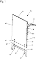
- FIG. 1 shows an isometric oblique view of a wall element 40 according to the application, in which a fitting 30 is integrated.
- the panel-shaped wall element 40 has a core 41, for example made from chipboard or from a medium or high-density fiberboard (MDF or HDF).
- the fitting 30 is arranged in the same plane as the core 41 and preferably with the same thickness, such that the core 41 and the fitting 30 complement one another in shape and size so that together they have the dimensions of the wall element 40 .
- the core 41 is formed in two parts and is divided in the plane of the lateral extent of the plate-shaped wall element 40 .
- a recess is introduced into each of the core halves, into which the fitting 30 is inserted.
- the core 41 or its two halves and the fitting 30 can be connected to one another via connecting elements that are not visible here, for example screws, clamps, pins, staples or the like.
- An adhesive connection can also be provided in addition to the connection elements mentioned or as the only connection.
- the core can also be made in one piece according to the invention with a recess into which the fitting 30 is inserted.
- Cover layers 42, 43 are applied, in particular glued or laminated, to the arrangement of the core 41 and the fitting 30 that is optionally connected thereto.
- the fitting 30 is selected with regard to its material and the material thickness, for example of side plates 301 of the fitting 30, so that it is not dented even during a laminating process, which could otherwise lead to an unevenness of the surface of the cover layers 42, 43. Smaller bumps in the side plates of the fitting 30 are compensated by the cover layers 42, 43. Such smaller bumps can, for example, be caused by bearing points of bolts that are used for the pivotable mounting of the lever mechanism 31 in the fitting 30 .
- the wall element 40 has connecting elements for connection to other furniture components.
- a U-shaped furniture leg 21 is shown as an example of such a further furniture component.
- threaded inserts 44 are concealed in the core 41 on a lower end face and serve as connecting elements for connecting the wall element 40 to the furniture leg 21 .
- Correspondingly positioned bores 211 are provided in the furniture leg 21 , through which screws 51 are guided, which are screwed into the threaded inserts 44 .
- the wall element 40 has all the necessary technical functional elements in order to be able to construct a piece of furniture even without an explicit furniture body.
- Figures 2a and 2b is a piece of furniture 10 according to the application, which has several of the 1 shown has wall elements 40 shown.
- Figure 2a shows the furniture in a partially assembled condition and Figure 2b then composed.
- the piece of furniture 10 comprises three wall elements 40, each with an integrated fitting 30, which are connected at their lower end face to a continuous sub-floor 22 as a furniture component.
- connecting elements integrated into the wall element 40 are used, for example those in 1 Threaded inserts 44 shown, into which screws (not visible here) are screwed.
- the boxes 23 are placed, which provide interior spaces of the piece of furniture 10 here by way of example. Since all technical functional elements such as the fitting 30 and the connecting elements are already contained in the wall elements 40, the boxes 23 can be designed freely with regard to the choice of material and can be made of glass, stone or metal, for example.
- FIG. 3 also shows an isometric representation of another example of a piece of furniture according to the application.
- two spaced and mutually parallel wall elements 40 are used, which in turn are similar to the example of FIG Fig. 2a, b placed on a sub-floor 22 and connected to it via the integrated connecting elements.
- the wall elements 40 also have comparable connecting elements on the opposite upper end face, via which they are connected to a top panel 24 placed on top.
- a shelf-like piece of furniture is created, the front surface of which can be closed entirely or in the area between the two wall elements 40 with a flap, not shown here.
- Longitudinal bores 45 are introduced as fastening means from the lower end face into the core 41, which merge into transverse bores 46, which are introduced into a side surface of the wall element 40 from a cover layer (here the cover layer 42).
- Rotary connectors 53 are inserted into the transverse bores 46 and interact with bolts 52 which are inserted through the furniture foot 21 into the longitudinal bores 45 .
- the bolts 52 have heads, not shown in the figure, at their end, which are gripped by the rotary connectors 53 .
- the surfaces engaging behind the head are preferably formed eccentrically in the rotary connector 53, so that the bolt 52 is pulled into the wall element 40 and the furniture leg is pulled up against the wall element 40 accordingly.
- a resilient connection between the furniture leg 21 and the wall element 40 is thus achieved.
- pierced dowels 212 can be provided on the furniture leg 21, which are inserted into the longitudinal bore 45 and through which the bolts 52 are guided.
- connection element formed in the wall element 40 can be provided not only on the lower end face shown here as an example for connection to the furniture leg 21, but also on the upper and/or rear end face. It is also pointed out that the connection to the furniture leg 21 is purely exemplary.
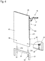
- the in the Figures 4-6 The connecting elements shown can, for example, also be used to connect to the subfloor 22 or the top floor 24 in the exemplary embodiments of FIG Figures 2a, 2b and 3 be used.
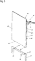
- a rotary connector 53 is also used in conjunction with a bolt, but in this case the rotary connector 53 is used in the furniture leg 21 in a corresponding bore 211.
- two bolts 47 are in turn arranged, for example, on the lower end face, which are inserted into the bore 211 of the furniture leg 21 and are fastened with the aid of the rotary connectors 53 .
- the bolts 47 can, for example, be provided with a thread and screwed into corresponding bores in the core 41 of the wall element 40 .
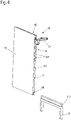
- a tongue and groove connection is provided between the wall element 40 and the further furniture component, here again by way of example a furniture leg 21 .
- a profile groove 48 is formed on the lower end face of the wall element 40, preferably over the entire width of the wall element 40, into which a correspondingly shaped profile strip 213, which is arranged or formed on the furniture leg 21, is inserted.
- the profile groove 48 has a keyhole-shaped or mushroom-shaped profile. It goes without saying that other undercut profiles such as a trapezoidal profile, a T-shaped profile or a Christmas tree profile can be used.
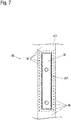
- FIG. 7 shows a front face 411 of a wall element 40 in the area of the fitting 30 in a top view.
- the edge band 49 is recessed. After the fitting 30 has been integrated, the edge band 49 is applied to the wall element 40 or to the front face 411 after the fitting 30 has been inserted into the wall element 40 .
- the edge band 49 is cut out in such a way that it partially rests on the fitting and, for example, covers the edges of the side plates 301 of the fitting 30 or other elements which are visible outside the opening of the fitting 30 .
- the outlines of the fitting 30 are indicated by dashed lines. Due to the arrangement of the edge band 49 on sections of the fitting 30, the fitting 30--apart from the extendable lever mechanism 31--is fully integrated into the wall element 40 and is no longer visible on its front face 411.
Landscapes
- Engineering & Computer Science (AREA)
- General Engineering & Computer Science (AREA)
- Mechanical Engineering (AREA)
- Furniture Connections (AREA)
- Assembled Shelves (AREA)
- Connection Of Plates (AREA)
- Cabinets, Racks, Or The Like Of Rigid Construction (AREA)
Description
- Erfindung betrifftein plattenförmiges Wandelement für ein Möbel, sowie ein Möbel mit einem solchen Wandelement.
- In der Regel weisen Möbel einen Möbelkorpus auf, der üblicherweise aus mindestens vier Wänden besteht, nämlich zwei Seitenwänden, einem Oberboden und einem Unterboden. Diese Wände sind fest miteinander verbunden und bilden eine bauliche Einheit, den genannten Möbelkorpus. Um eine nach vorne weisende Öffnung des Möbelkorpus verschließen zu können, werden innen an dem Möbelkorpus Beschläge montiert, die Türen, Klappen, Schubkästen mit einer Schubkastenfront oder sonstige bewegbare Möbelteile führen.
- Alternativ zu einer Befestigung der Beschläge am Möbelkorpus ist es bei Türscharnieren bekannt, in eine Stirnseite einer Seitenwand des Möbelkorpus eine Tasche zu fräsen, in die das Türscharnier von vorne einsetzbar ist. Ein zum Einsatz in einer derartigen eingefrästen Tasche geeignetes Scharnier ist beispielsweise aus der Druckschrift
DE 155 9963 bekannt. - Eine weitere Art, ein Scharnier innerhalb eines Möbelkorpus zu montieren, zeigt die Druckschrift
DE 20 2013 003 189 U1 Hierbei ist eine Seitenwand des Möbelkorpus abschnittsweise aus unterschiedlichen Teilen aufgebaut, wobei ein hinterer, einer Möbelfront abgewandter Teil herkömmlich ausgebildet ist, z.B. durch ein beschichtetes Holzelement. Ein vorderer Teil der Seitenwand ist durch ein in der genannten Schrift nicht näher beschriebenes Gehäuse gebildet, das mindestens eine stirnseitige Öffnung aufweist, in die ein Beschlag eingeschoben werden kann. Auf diese Weise können auch Beschläge mit einer größeren Einbautiefe eingesetzt werden, was mit einer stirnseitig vorgenommenen Einfräsung nicht möglich ist. - Unabhängig davon, ob Scharniere innen auf eine Seitenwand des Möbelkorpus aufgesetzt oder in die Seitenwand eingesetzt werden, basieren bekannte Möbel auf der Verwendung eines in der Regel quaderförmigen Möbelkorpus als Grundelement, an dem bewegbare Möbelteile über Beschläge befestigt sind. Andere ähnliche Möbel sind zum Beispiel aus
WO2017029199A1 undWO2010130570A1 bekannt. - Es ist eine Aufgabe der vorliegenden Erfindung, ein Möbel zu schaffen, das auf einem flexibler einzusetzenden Grundelement basiert.
- Diese Aufgabe wird gelöst durch ein plattenförmiges Wandelement für ein Möbel mit den Merkmalen des unabhängigen Anspruchs. Vorteilhafte Ausgestaltungen und Weiterbildungen sind in den abhängigen Ansprüchen angegeben.
- Ein erfindungsgemäßes Möbel zeichnet sich dadurch aus, dass es zumindest ein plattenförmiges Wandelement nach dem unabhängigen Anspruch aufweist.
- Ein erfindungsgemäßes Möbel basiert somit nicht auf einem vorgefertigten Möbelkorpus, sondern weist das mindestens eine plattenförmige Wandelement als Grundbaustein auf, das mit weiteren Möbelkomponenten verbunden werden kann. Dadurch, dass das Wandelement sowohl den Beschlag als auch Verbindungselemente integral enthält, ermöglicht es einen flexiblen Aufbau eines Möbels unter Verwendung von weiteren Komponenten, die keine weiteren Funktionselemente aufnehmen müssen. Das führt zu einer großen Flexibilität in beispielsweise der Materialauswahl und der Dimensionierung der weiteren Möbelkomponenten. Diese können beispielsweise aus schwieriger zu bearbeitenden Materialien wie Glas, Stein oder Metall gefertigt sein, da sie z.B. keine Beschläge aufnehmen müssen.
- Im Rahmen der Anmeldung kann das Wandelement im Möbel in jeder Ausrichtung eingesetzt sein. Insbesondere kann das Wandelement eine (vertikale) Seitenwand oder Zwischenwand sein oder auch ein (horizontaler) Ober-, Unter- oder Zwischenboden. Auch eine schräge, beispielsweise diagonale Anordnung ist möglich.
- In einer vorteilhaften Ausgestaltung des Möbels kann als weitere Möbelkomponente ein seinerseits plattenförmiges Element eingesetzt werden, das eine Fläche aufweist, auf der das mindestens eine plattenförmige Wandelement mit einer Stirnseite anliegt. Auf diese Weise kann ein Regal-ähnlicher Aufbau erreicht werden, wobei Klappen oder Türen zum Verschließen von Fächern, die durch die plattenförmigen Wände bzw. die weiteren plattenförmigen Bauelemente gebildet sind, vorgesehen werden können.
- Bevorzugt sind mindestens zwei plattenförmige Wandelemente mit integriertem Beschlag vorhanden, die parallel zueinander angeordnet sind. Zwischen beiden parallelen Wandelementen ist ein quaderförmiges Element, z.B. ein nach vorne offener Kasten, eingesetzt. Bevorzugt ist dieses quaderförmige Element aus einem anderen Material gefertigt, als das Wandelement. Während das Wandelement bevorzugt auf einem Holz- oder holzbasierten und bevorzugt spanend bearbeitbaren Werkstoff als Grundwerkstoff gefertigt ist, kann das quaderförmige Element aus Werkstoffen wie Glas, Stein oder Beton gefertigt sein, die schwer, insbesondere nicht spanend zu bearbeiten sind und ihrerseits Beschläge nicht oder nur mit hohem Fertigungsaufwand aufnehmen können.
- In einer vorteilhaften Ausgestaltung des Möbels bilden der Unter- und/oder Oberboden die Breite des Möbels und wenigstens ein plattenförmiges Wandelement ist mindestens 10 cm von einer Außenkante des Unter- und/oder Oberbodens beabstandet. Auf diese Weise unterteilt das plattenförmige Wandelement zusätzlich den Innenraum des Möbels. Es führt den Beschlag und dient gleichzeitig als Organisations- oder Strukturierungselement für den Innenraum.
- Die Aufgabe wird gelöst durch ein plattenförmiges Wandelement, das einen integrierten Beschlag und integrierte Verbindungselemente zur Verbindung mit weiteren Möbelkomponenten aufweist. Ein derartiges Wandelement ermöglicht den Aufbau des zuvor beschriebenen Möbels. Es ergeben sich somit die im Zusammenhang mit dem Möbel beschriebenen Vorteile.
- In vorteilhaften Ausgestaltungen des Wandelements ist das mindestens eine Verbindungselement ein Gewindeeinsatz oder eine Kombination aus einem Lang- und einem Querloch zur Aufnahme eines Drehverbinders. Die mit dem Wandelement zu verbindende weitere Möbelkomponente kann entsprechend über Schrauben oder Bolzen mit einem Verbindungskopf, der vom Drehverbinder hintergriffen wird, befestigt werden. Auch kann als Verbindungselement in dem Wandelement eine Profilnut ausgebildet sein oder eine Feder angeordnet oder ausgebildet sein. An der zu verbindenden weiteren Möbelkomponente ist entsprechend einer passende Feder, z.B. in Form einer Profilleiste, bzw. eine passende Profilnut vorhanden.
- Erfindungsgemäß weist das Wandelement mindestens einen Kern auf, der in einer Ebene mit dem Beschlag angeordnet ist, wobei der mindestens eine Kern und der Beschlag zwischen zwei durchgehenden
- Decklagen angeordnet sind. Ein derart aufgebautes Wandelement zeichnet sich durch eine durchgehend gleiche Optik und Haptik seiner Seitenfläche aus. Der Kern ist erfindungsgemäß aus Holz oder einem Holzverbundwerkstoff wie MDF (Medium-Density Fiberboard) oder HDF (High-Density Fiberboard) gefertigt .
- Der Beschlag wird vorteilhaft bereits beim Zusammenfügen des Wandelements in dieses integriert. So kann auch ein großer Beschlag mit einer großen Einbautiefe, der sich beispielsweise sogar über die im Wesentlichen gesamte Breite des Wandelements erstreckt, eingesetzt werden. Insbesondere können Klappenbeschläge eingesetzt werden, deren Hebelwerk vollständig (ggf. bis auf Montageelemente, an denen das bewegbare Möbelteil befestigt wird) in eine Öffnung in einer Stirnseite des Wandelements eingefahren werden kann.
- Erfindungsgemäß sind die beiden durchgehenden Decklagen flächig mit dem mindestens einen Kern und/oder dem Beschlag verbunden, beispielsweise auflaminiert. Die flächige Verbindung stabilisiert das Wandelement und ermöglicht die Verwendung von relativ dünnen Decklagen mit Dicken im Bereich von zehntel Millimetern.
- Die Erfindung wird nachfolgend anhand von Ausführungsbeispielen mithilfe von Figuren näher erläutert. Die Figuren zeigen:
- Fig. 1
- eine isometrische Explosionsdarstellung einer Seitenwand für ein Möbel mit einem Möbelfuß;
- Fig. 2a, b
- unterschiedliche isometrische Darstellungen eines Möbels mit mehreren anmeldungsgemäßen Wandelementen;
- Fig. 3
- ein weiteres Ausführungsbeispiel eines Möbels mit zwei anmeldungsgemäßen Wandelementen in einer isometrischen Darstellung;
- Fig. 4-6
- jeweils ein weiteres Ausführungsbeispiel eines Wandelements mit einem Möbelfuß in einer Darstellung analog zu
Fig. 1 ; und - Fig. 7
- eine schematische Draufsicht auf eine vordere Stirnseite eines Wandelements im Bereich eines eingesetzten Beschlags.
-
Fig. 1 zeigt in einer isometrischen Schrägansicht ein anmeldungsgemäßes Wandelement 40, in das ein Beschlag 30 integriert ist. - Das plattenförmige Wandelement 40 weist einen Kern 41 auf, beispielsweise gefertigt aus einer Spanplatte oder aus einer mittel- oder hochverdichteten Faserplatte (MDF bzw. HDF). In gleicher Ebene wie der Kern 41 und bevorzugt mit gleicher Dicke ist der Beschlag 30 angeordnet, derart, dass sich der Kern 41 und der Beschlag 30 in Form und Größe so ergänzen, dass sie zusammen die Abmessungen des Wandelements 40 aufweisen.
- Erfindungsgemäß ist der Kern 41 zweiteilig ausgebildet und in der Ebene der lateralen Ausdehnung des plattenförmigen Wandelements 40 geteilt. In jede der Kernhälften ist eine Aussparung eingebracht, in die der Beschlag 30 eingesetzt ist. Der Kern 41 bzw. seine beiden Hälften und der Beschlag 30 können über hier nicht sichtbare Verbindungselemente, beispielsweise Schrauben, Klammern, Stifte, Krampen oder ähnliches miteinander verbunden sein. Auch eine Klebeverbindung kann neben den genannten Verbindungselementen oder als einzige Verbindung vorgesehen sein.
- Alternativ zu dem dargestellten zweiteiligen Kern 41 kann der Kern erfindungsgemäß auch einteilig ausgebildet sein mit einer Ausnehmung, in die der Beschlag 30 eingesetzt ist.
- Auf die Anordnung aus dem Kern 41 und dem damit gegebenenfalls verbundenen Beschlag 30 werden von jeder Seite her Decklagen 42, 43 aufgebracht, insbesondere geklebt oder auflaminiert. Der Beschlag 30 ist dabei bezüglich seines Materials und der Materialstärke beispielsweise von Seitenplatten 301 des Beschlags 30 so gewählt, dass er auch bei einem Laminierprozess nicht eingedrückt wird, was andernfalls zu einer Unebenheit der Oberfläche der Decklagen 42, 43 führen könnte. Kleinere Unebenheiten in den Seitenplatten des Beschlags 30 werden durch die Decklagen 42, 43 ausgeglichen. Solche kleineren Unebenheiten können beispielsweise durch Lagerstellen von Bolzen, die der schwenkbaren Lagerung des Hebelwerks 31 im Beschlag 30 dienen, herrühren.
- Der Beschlag 30 ist vorliegend ein Klappenbeschlag, der eine um eine horizontale Achse schwenkbare Klappe führt, über die eine Möbelöffnung verschlossen werden kann. Eine solche Klappe ist aus Gründen der Übersichtlichkeit in der
Fig. 1 nicht dargestellt. Vom Beschlag 30 ist lediglich ein ausgefahrener Teil eines Hebelwerks 31 in derFig. 1 sichtbar. Der Beschlag 30 ist so in das Wandelement 40 integriert, dass in geschlossenem Zustand der vom Beschlag 30 geführten Klappe das Hebelwerk 31 gegebenenfalls bis auf Montageelemente zur Verbindung mit der Klappe vollständig in das Wandelement 40, konkret in eine vordere Stirnseite 411, eingefahren ist. - Darüber hinaus weist das Wandelement 40 Verbindungselemente zur Verbindung mit weiteren Möbelkomponenten auf. In der
Fig. 1 ist beispielhaft ein u-förmiger Möbelfuß 21 als eine solche weitere Möbelkomponente dargestellt. - Im Wandelement 40 sind an einer unteren Stirnseite Gewindeeinsätze 44 verdeckt in den Kern 41 eingesetzt, die als Verbindungselemente der Verbindung des Wandelements 40 mit dem Möbelfuß 21 dienen. Im Möbelfuß 21 sind entsprechend positionierte Bohrungen 211 angebracht, durch die Schrauben 51 geführt sind, die in die Gewindeeinsätze 44 eingeschraubt werden.
- Mit dem integrierten Beschlag 30 sowie den Verbindungselementen weist das Wandelement 40 alle notwendigen technischen Funktionselemente auf, um ein Möbel auch ohne einen expliziten Möbelkorpus aufbauen zu können.
- In den
Fig. 2a und 2b ist ein anmeldungsgemäßes Möbel 10, das mehrere der inFig. 1 gezeigten Wandelemente 40 aufweist, dargestellt.Fig. 2a zeigt das Möbel in einem teils zusammengesetzten Zustand undFig. 2b dann zusammengesetzt. - Das Möbel 10 umfasst im dargestellten Zustand drei Wandelemente 40 mit jeweils integriertem Beschlag 30, die mit ihrer unteren Stirnseite mit einem durchgängigen Unterboden 22 als Möbelkomponente verbunden sind. Zur Verbindung werden wiederum in das Wandelement 40 integrierte Verbindungselemente eingesetzt, beispielsweise die in
Fig. 1 gezeigten Gewindeeinsätze 44, in die von unten hier nicht sichtbare Schrauben eingeschraubt werden. - Zwischen zwei der Wandelemente 40 bzw. an eines der Wandelemente 40 werden nach vorne offene Kästen 23 eingestellt, die hier beispielhaft Innenräume des Möbels 10 bereitstellen. Da alle technischen Funktionselemente wie der Beschlag 30 sowie die Verbindungselemente bereits in den Wandelementen 40 enthalten sind, können die Kästen 23 im Hinblick auf die Materialwahl frei gestaltet werden und beispielsweise aus Glas, Stein oder Metall aufgebaut sein.
-
Fig. 3 zeigt ebenfalls in einer isometrischen Darstellung ein weiteres Beispiel eines anmeldungsgemäßen Möbels. Hierbei werden zwei beabstandete und parallel zueinander ausgerichtete Wandelemente 40 eingesetzt, die wiederum ähnlich wie beim Beispiel derFig. 2a, b auf einen Unterboden 22 aufgestellt und über die integrierten Verbindungselemente mit diesem verbunden sind. - Die Wandelemente 40 weisen zudem vergleichbare Verbindungselemente an der gegenüberliegenden oberen Stirnseite auf, über die sie mit einem oben aufgesetzten Oberboden 24 verbunden sind. Es entsteht ein Regal-ähnliches Möbel, dessen vordere Fläche ganz oder im Bereich zwischen den beiden Wandelementen 40 mit einer hier nicht dargestellten Klappe verschließbar ist.
- In den
Fig. 4 ,5 und6 sind in jeweils gleicher Art wie inFig. 1 weitere Ausführungsbeispiele eines Wandelements 40 mit integriertem Beschlag 30 und integrierten Verbindungselementen zur Verbindung mit weiteren Möbelkomponenten gezeigt. - Gleiche Bezugszeichen kennzeichnen in diesen Figuren gleiche oder gleichwirkende Elemente wie bei den zuvor beschriebenen Figuren. Im Hinblick auf den Grundaufbau des Wandelements 40 wird auf die Ausführungen zu
Fig. 1 verwiesen. - Beim Ausführungsbeispiel der
Fig. 4 sind als Befestigungsmittel von der unteren Stirnseite in den Kern 41 Längsbohrungen 45 eingebracht, die in Querbohrungen 46 übergehen, die von einer Decklage aus (hier der Decklage 42) in eine Seitenfläche des Wandelements 40 eingebracht sind. In die Querbohrungen 46 sind Drehverbinder 53 eingesetzt, die mit Bolzen 52 zusammenwirken, die durch den Möbelfuß 21 in die Längsbohrungen 45 eingesetzt werden. Die Bolzen 52 haben an ihrem Ende in der Figur nicht dargestellte Köpfe, die von den Drehverbindern 53 gegriffen werden. Die den Kopf hintergreifenden Flächen sind dabei bevorzugt exzentrisch im Drehverbinder 53 ausgebildet, sodass der Bolzen 52 in das Wandelement 40 hineingezogen wird und entsprechend der Möbelfuß an das Wandelement 40 herangezogen wird. So wird eine belastbare Verbindung zwischen dem Möbelfuß 21 und dem Wandelement 40 erzielt. Zusätzlich können wie beim dargestellten Beispiel am Möbelfuß 21 durchbohrte Dübel 212 vorgesehen sein, die in die Längsbohrung 45 eingesteckt werden und durch die die Bolzen 52 geführt sind. - Es versteht sich, dass die dargestellte Art der Verbindung und das in dem Wandelement 40 ausgebildete Verbindungselement nicht nur an der hier beispielhaft zur Verbindung mit dem Möbelfuß 21 gezeigten unteren Stirnseite vorgesehen sein kann, sondern auch an der oberen und/oder der hinteren Stirnseite. Weiter wird darauf hingewiesen, dass die Verbindung mit dem Möbelfuß 21 rein beispielhaft ist. Die in den
Fig. 4-6 gezeigten Verbindungselemente können beispielsweise auch zur Verbindung mit dem Unterboden 22 bzw. dem Oberboden 24 in dem Ausführungsbeispielen derFig. 2a, 2b und3 eingesetzt werden. - Beim Ausführungsbeispiel der
Fig. 5 wird ebenfalls ein Drehverbinder 53 in Verbindung mit einem Bolzen eingesetzt, wobei hierbei jedoch der Drehverbinder 53 im Möbelfuß 21 in einer entsprechenden Bohrung 211 eingesetzt wird. Am Wandelement 40 sind hier wiederum beispielhaft an der unteren Stirnseite zwei Bolzen 47 angeordnet, die in die Bohrung 211 des Möbelfußes 21 gesteckt werden und mithilfe der Drehverbinder 53 befestigt werden. Die Bolzen 47 können beispielsweise mit einem Gewinde versehen sein und in entsprechende Bohrungen in den Kern 41 des Wandelements 40 eingeschraubt sein. - Beim Beispiel der
Fig. 6 ist eine Nut- und Federverbindung zwischen dem Wandelement 40 und der weiteren Möbelkomponente, hier wiederum beispielhaft ein Möbelfuß 21, vorgesehen. Dazu ist an der unteren Stirnseite des Wandelements 40 eine Profilnut 48 bevorzugt über die gesamte Breite des Wandelements 40 ausgebildet, in die eine entsprechend geformte Profilleiste 213 eingeschoben wird, die am Möbelfuß 21 angeordnet bzw. ausgebildet ist. Beispielhaft weist die Profilnut 48 ein schlüssellochförmiges bzw. pilzförmiges Profil auf. Es versteht sich, dass andere hinterschnittene Profile wie beispielsweise ein Trapezprofil, ein T-förmiges Profil oder ein Tannenbaumprofil Verwendung finden können. -
Fig. 7 zeigt in einer Draufsicht eine vordere Stirnseite 411 eines Wandelements 40 im Bereich des Beschlags 30. Bei diesem Ausführungsbeispiel ist ein Kantenumleimer 49 als Schmalseitenbeschichtung auf die vordere Stirnseite 211 des Kerns 21 und damit der des Wandelements 40 aufgebracht. - Im Bereich der Öffnung des Beschlags 30, aus der beispielsweise das in dieser Darstellung nicht sichtbare Hebelwerk 31 ausfährt, ist der Kantenumleimer 49 ausgespart. Der Kantenumleimer 49 wird nach Integration des Beschlags 30 in das Wandelement 40 oder auch nach Einsetzen des Beschlags 30 in das Wandelement 40 auf die vordere Stirnseite 411 aufgebracht.
- Der Kantenumleimer 49 ist so ausgeschnitten, dass er abschnittsweise auf dem Beschlag aufliegt und z.B. die Kanten der Seitenplatten 301 des Beschlags 30 oder anderer außerhalb der Öffnung des Beschlags 30 sichtbarer Elemente abdeckt. In der
Fig. 6 sind die Umrisse des Beschlags 30 gestrichelt angedeutet. Durch die Anordnung des Kantenumleimers 49 auch auf Abschnitten des Beschlags 30 ist der Beschlag 30 - bis auf das ausfahrbare Hebelwerk 31 - vollständig in das Wandelement 40 integriert und an dessen vorderer Stirnseite 411 nicht mehr sichtbar. -
- 10
- Möbel
- 21
- Möbelfuß
- 211
- Bohrung
- 212
- Dübel
- 213
- Profilleiste
- 22
- Unterboden
- 23
- Kasten
- 24
- Oberboden
- 30
- Beschlag
- 301
- Seitenplatte
- 31
- Hebelwerk
- 40
- Wandelement
- 41
- Kern
- 411
- vordere Stirnseite
- 42,43
- Decklage
- 44
- Gewindeeinsatz
- 45
- Längsbohrung
- 46
- Querbohrung
- 47
- Bolzen
- 48
- Profilnut
- 49
- Kantenumleimer
- 51
- Schraube
- 52
- Bolzen
- 53
- Drehverbinder
Claims (12)
- Plattenförmiges Wandelement (40) für ein Möbel (10), aufweisend mindestens einen integrierten Beschlag (30) und mindestens ein integriertes Verbindungselement zur Verbindung mit mindestens einer weiteren Möbelkomponente, wobei
das plattenförmige Wandelement (40) mindestens einen Kern (41) aufweist, der aus Holz oder einem Holzverbundwerkstoff gefertigt ist, in einer Ebene mit dem Beschlag (30) angeordnet ist und der einteilig mit einer Ausnehmung ausgebildet ist oder der zweiteilig lateral in zwei Kernhälften geteilt ist, wobei in jede der Kernhälften eine Aussparung eingebracht ist, um den Beschlag (30) aufzunehmen, wobei der mindestens eine Kern (41) und der Beschlag (30) zwischen zwei durchgehenden Decklagen (42, 43) angeordnet sind, wobei die beiden durchgehenden Decklagen (42, 43) flächig mit dem mindestens einen Kern (41) und/oder dem Beschlag (30) verbunden sind, und wobei der Beschlag (30) ein Hebelwerk (31) aufweist, das ein bewegliche Möbelteil führt. - Wandelement (40) nach Anspruch 1, bei dem das mindestens eine Verbindungselement ein Gewindeeinsatz (44) ist.
- Wandelement (40) nach Anspruch 1 oder 2, bei dem das mindestens eine Verbindungselement eine Kombination aus einem Lang- und einem Querloch (45, 46) zur Aufnahme eines Drehverbinders (53) ist.
- Wandelement (40) nach einem der Ansprüche 1 bis 3, bei dem das mindestens eine Verbindungselement eine Profilnut (48) oder eine Feder ist.
- Wandelement (40) nach einem der Ansprüche 1 bis 4, bei dem die beiden durchgehenden Decklagen (42, 43) flächig auf den mindestens einen Kern (41) und/oder den Beschlag (30) auflaminiert sind.
- Wandelement (40) nach einem der Ansprüche 1 bis 5, bei der sich das Hebelwerk (31) im geschlossenen Zustand des beweglichen Möbelteils vollständig zwischen den Decklagen (42, 43) befindet.
- Möbel (10) mit mindestens einem Beschlag (30) zur Führung eines bewegbaren Möbelteils, aufweisend mindestens ein plattenförmiges Wandelement (40) gemäß einem der Ansprüche 1 bis 6.
- Möbel (10) nach Anspruch 7, aufweisend mindestens ein plattenförmiges Element als weitere Möbelkomponente, mit einer Fläche, auf der das mindestens eine plattenförmige Wandelement (40) mit einer Stirnseite anliegt.
- Möbel (10) nach Anspruch 8, bei dem das mindestens ein plattenförmiges Element ein Unter- und/oder ein Oberboden (22, 24) ist.
- Möbel (10) nach Anspruch 9, bei dem mindestens zwei plattenförmige Wandelemente (40) parallel zueinander und beabstandet voneinander angeordnet sind.
- Möbel (10) nach Anspruch 10, bei dem zwischen den beiden plattenförmigen Wandelementen (40) ein Kasten (23) angeordnet ist.
- Möbel (10) nach Anspruch 9, bei dem der Unter- und/oder Oberboden (22, 24) die Breite des Möbels bilden und wenigstens ein plattenförmiges Wandelement (40) mindestens 10 cm von einer Außenkante des Unter- und/oder Oberbodens (22, 24) beabstandet ist.
Applications Claiming Priority (2)
| Application Number | Priority Date | Filing Date | Title |
|---|---|---|---|
| DE102017104183.4A DE102017104183A1 (de) | 2017-02-28 | 2017-02-28 | Möbel und Wandelement für ein Möbel |
| PCT/EP2018/054531 WO2018158153A1 (de) | 2017-02-28 | 2018-02-23 | Möbel und wandelement für ein möbel |
Publications (2)
| Publication Number | Publication Date |
|---|---|
| EP3589161A1 EP3589161A1 (de) | 2020-01-08 |
| EP3589161B1 true EP3589161B1 (de) | 2022-03-30 |
Family
ID=61557258
Family Applications (1)
| Application Number | Title | Priority Date | Filing Date |
|---|---|---|---|
| EP18708374.6A Active EP3589161B1 (de) | 2017-02-28 | 2018-02-23 | Möbel und wandelement für ein möbel |
Country Status (6)
| Country | Link |
|---|---|
| US (1) | US10881207B2 (de) |
| EP (1) | EP3589161B1 (de) |
| CN (1) | CN110520012B (de) |
| DE (1) | DE102017104183A1 (de) |
| PL (1) | PL3589161T3 (de) |
| WO (1) | WO2018158153A1 (de) |
Families Citing this family (12)
| Publication number | Priority date | Publication date | Assignee | Title |
|---|---|---|---|---|
| DE102017104170A1 (de) * | 2017-02-28 | 2018-08-30 | ambigence GmbH & Co. KG | Wand eines Möbelkorpus, Verfahren zur Herstellung einer solchen Wand und Möbelkorpus oder Möbel mit einer solchen Wand |
| DE102017104185A1 (de) * | 2017-02-28 | 2018-08-30 | ambigence GmbH & Co. KG | Bauplatte für eine Möbelwand, Verfahren zur Herstellung einer solchen Bauplatte und einer Möbelwand sowie Möbelkorpus oder Möbel mit einer Möbelwand |
| DE102017126367A1 (de) | 2017-11-10 | 2019-05-16 | Hettich-Oni Gmbh & Co. Kg | Klappenbeschlag für ein Möbel, Seitenwand eines Möbelkorpus und Möbel mit einer Seitenwand |
| DE102018100204A1 (de) * | 2018-01-05 | 2019-07-11 | ambigence GmbH & Co. KG | Verfahren zum Integrieren eines Montageelementes für einen Bewegungsbeschlag in eine Möbelplatte sowie Möbelplatte mit integriertem Montageelement |
| ES2886502T3 (es) * | 2018-05-17 | 2021-12-20 | Kesseboehmer Holding Kg | Herraje de tapa para la fijación pivotante de una tapa de mueble a una carcasa de mueble |
| DE102018119539A1 (de) * | 2018-08-10 | 2020-02-13 | ambigence GmbH & Co. KG | Wand für ein Möbel, Verfahren zur Herstellung einer solchen Wand und Möbelkorpus oder Möbel mit einer solchen Wand |
| DE102018130974A1 (de) * | 2018-12-05 | 2020-06-10 | ambigence GmbH & Co. KG | Möbelkomponente und Verfahren zur Herstellung |
| DE102019102491A1 (de) * | 2019-01-31 | 2020-08-06 | Hettich-Oni Gmbh & Co. Kg | Klappenbeschlag für ein Möbel |
| AT522656B1 (de) * | 2019-05-17 | 2025-04-15 | Blum Gmbh Julius | Möbelantrieb |
| AT17215U1 (de) * | 2020-03-03 | 2021-09-15 | Blum Gmbh Julius | Möbelbeschlag |
| AT524025B1 (de) * | 2020-09-14 | 2022-02-15 | Blum Gmbh Julius | Wand für einen Möbelkorpus und Verfahren zu deren Herstellung |
| JP1723091S (ja) * | 2020-12-11 | 2022-08-23 | 家具壁面構成部 |
Family Cites Families (29)
| Publication number | Priority date | Publication date | Assignee | Title |
|---|---|---|---|---|
| US2360451A (en) | 1942-06-02 | 1944-10-17 | Stone Abraham | Collapsible clothing container |
| US3023910A (en) * | 1957-01-24 | 1962-03-06 | Shirley E Schless | Support for sliding shelves |
| DE1867127U (de) | 1962-05-24 | 1963-02-14 | Fritz Schroeder K G Moebelwerk | Einbauwand. |
| DE1900741U (de) | 1964-04-25 | 1964-09-17 | Wilhelm Broelhorst & Co | Spuelkastenunterbau. |
| DE1559963A1 (de) | 1966-12-21 | 1969-12-18 | Ernst Maurmann Kg | Scharnier fuer Tueren bzw. Klappen u.dgl.,vorzugsweise an Moebeln |
| US3951558A (en) * | 1974-11-22 | 1976-04-20 | Komarov Anatoli N | Apparatus for demountably coupling two members |
| IT1028807B (it) | 1975-04-23 | 1979-02-10 | Sts Societa Toscana Semilavo R | Struttura ad elementi componibili, per l formazione di mobili scaffalature, rivestimenti ed altro |
| ES227935Y (es) * | 1977-04-20 | 1977-11-16 | Modulo fijador para la sustentacion de bandejas. | |
| US4108514A (en) | 1977-10-18 | 1978-08-22 | Dual Gebruder Steidinger | Phonostand |
| US5720547A (en) * | 1995-07-11 | 1998-02-24 | Baird; Merrill F. | Modular storage bins |
| US7959242B2 (en) * | 2003-06-02 | 2011-06-14 | Accuride International Inc. | Pocket door cabinet and slide assembly |
| US8641155B2 (en) * | 2007-07-26 | 2014-02-04 | David Lee | Modular furniture system |
| DE202009004806U1 (de) | 2009-05-12 | 2010-10-14 | Hettich Holding Gmbh & Co. Ohg | Möbel |
| DE202009004805U1 (de) | 2009-05-12 | 2010-09-23 | Hettich Holding Gmbh & Co. Ohg | Möbelwand und Möbel |
| CN202179292U (zh) * | 2011-08-02 | 2012-04-04 | 广州市卓明建材有限公司 | 无缝免焊接不锈钢柜体组装结构 |
| DE102013100481B4 (de) * | 2013-01-17 | 2015-08-06 | Wolfgang Fünfgeld | Baukastensystem, insbesondere für Möbel, Messeaufbauten oder dergleichen und Möbelstück oder Messeaufbau |
| DE202013003189U1 (de) | 2013-04-08 | 2014-07-10 | Grass Gmbh & Co. Kg | Wandelement für einen Möbelkorpus mit einer Korpuswand |
| JP2015181755A (ja) | 2014-03-25 | 2015-10-22 | 卓也 前川 | 組立式家具 |
| IL231941A (en) * | 2014-04-03 | 2015-07-30 | Oren Sitton | Printable and bending boards, structures containing them and methods for making them |
| DE102014109712B4 (de) * | 2014-07-10 | 2017-10-19 | Nobilia-Werke J.Stickling Gmbh & Co.Kg | Schrankmöbel und Verfahren zur Montage eines Schrankmöbels |
| US9386847B1 (en) * | 2014-07-17 | 2016-07-12 | Austin Hardware And Supply, Inc. | Mounting system |
| DE202014105730U1 (de) * | 2014-11-27 | 2016-03-02 | Grass Gmbh & Co. Kg | Wandelement eines Möbels und Möbel mit einem solchen Wandelement |
| WO2016207334A1 (de) * | 2015-06-26 | 2016-12-29 | Lutz Dönhoff | Verbindungsystem zum zusammensetzen eines modularen raumsystems |
| DE102015113427A1 (de) * | 2015-08-14 | 2017-02-16 | Form Orange Produktentwicklung | Wandschrank, insbesondere Küchen-Wandschrank |
| DE102017104182A1 (de) * | 2017-02-28 | 2018-08-30 | ambigence GmbH & Co. KG | Möbel |
| DE102017104170A1 (de) * | 2017-02-28 | 2018-08-30 | ambigence GmbH & Co. KG | Wand eines Möbelkorpus, Verfahren zur Herstellung einer solchen Wand und Möbelkorpus oder Möbel mit einer solchen Wand |
| DE102017104171A1 (de) * | 2017-02-28 | 2018-08-30 | ambigence GmbH & Co. KG | Wand für einen Möbelkorpus, Verfahren zur Herstellung einer solchen Wand und Möbelkorpus oder Möbel mit einer solchen Wand |
| DE102017104169A1 (de) * | 2017-02-28 | 2018-08-30 | ambigence GmbH & Co. KG | Wand eines Möbelkorpus, Verfahren zur Herstellung einer solchen Wand und Möbelkorpus oder Möbel mit einer solchen Wand |
| DE202018102089U1 (de) * | 2018-04-17 | 2019-07-18 | Grass Gmbh | Vorrichtung zur Bewegung eines an einem Möbelkorpus eines Möbels aufgenommenen Möbelteils |
-
2017
- 2017-02-28 DE DE102017104183.4A patent/DE102017104183A1/de not_active Withdrawn
-
2018
- 2018-02-23 WO PCT/EP2018/054531 patent/WO2018158153A1/de not_active Ceased
- 2018-02-23 CN CN201880014628.3A patent/CN110520012B/zh active Active
- 2018-02-23 EP EP18708374.6A patent/EP3589161B1/de active Active
- 2018-02-23 PL PL18708374.6T patent/PL3589161T3/pl unknown
- 2018-02-23 US US16/489,174 patent/US10881207B2/en active Active
Non-Patent Citations (1)
| Title |
|---|
| None * |
Also Published As
| Publication number | Publication date |
|---|---|
| US10881207B2 (en) | 2021-01-05 |
| EP3589161A1 (de) | 2020-01-08 |
| WO2018158153A1 (de) | 2018-09-07 |
| DE102017104183A1 (de) | 2018-08-30 |
| CN110520012A (zh) | 2019-11-29 |
| PL3589161T3 (pl) | 2022-08-08 |
| US20190380494A1 (en) | 2019-12-19 |
| CN110520012B (zh) | 2022-07-12 |
Similar Documents
| Publication | Publication Date | Title |
|---|---|---|
| EP3589161B1 (de) | Möbel und wandelement für ein möbel | |
| EP3589165B1 (de) | Wand für einen möbelkorpus, verfahren zur herstellung einer solchen wand und möbelkorpus oder möbel mit einer solchen wand | |
| EP3589163B1 (de) | Wand eines möbelkorpus, verfahren zur herstellung einer solchen wand und möbelkorpus oder möbel mit einer solchen wand | |
| EP3589166B1 (de) | Bauplatte für eine möbelwand und verfahren zur herstellung einer solchen bauplatte und einer möbelwand | |
| EP3589164B1 (de) | Wand eines möbelkorpus, verfahren zur herstellung einer solchen wand und möbelkorpus oder möbel mit einer solchen wand | |
| EP3589811B1 (de) | Möbel mit aufsetzbarem platteförmigem verbundelement mit integriertem beschlag | |
| EP3735152B1 (de) | Anordnung einer möbelplatte und eines bewegungsbeschlages mit integriertem montageelement für den bewegungsbeschlag, möbelkörper und möbel, die eine solche möbelplatte enthalten | |
| EP3589160B1 (de) | Wand eines möbelkorpus und möbelkorpus oder möbel mit einer solchen wand | |
| CH696889A5 (de) | Verriegelungselement und Verfahren zur Verriegelung von zwei Platten. | |
| EP3589162B1 (de) | Möbel mit äusserem aufsatzelement mit integriertem beschlag | |
| EP3115521B1 (de) | Beschlag und beschlagsystem zum reversiblen verbinden von flächigen elementen sowie modulares stellwandsystem | |
| EP2039841A1 (de) | Schrank- oder Regalmöbel | |
| WO2020030602A1 (de) | Wand für ein möbel, verfahren zur herstellung einer solchen wand und möbelkorpus oder möbel mit einer solchen wand | |
| EP2147778B1 (de) | Leichtbauplatte für den Möbelbau | |
| WO2018158156A1 (de) | Wand eines möbelkorpus und möbelkorpus oder möbel mit einer solchen wand | |
| EP3243996B1 (de) | Plattenförmiges holzsystem und verfahren zur herstellung eines plattenförmigen holzsystems | |
| DE102017104176B4 (de) | Möbelkorpus und Möbel | |
| AT412412B (de) | Adapterprofil | |
| DE102022131160A1 (de) | Einbauelement zur Aufbewahrung von Gegenständen in einer Trockenbauwand und Anordnung hiermit | |
| EP4289310A1 (de) | Einbauelement zur aufbewahrung von gegenständen in einer trockenbauwand und anordnung hiermit | |
| DE102017104175A1 (de) | Wandeinbaumöbel und Bauelement für ein Wandeinbaumöbel | |
| DE2912582A1 (de) | Aus bauelementen aufgebaute schrankstruktur |
Legal Events
| Date | Code | Title | Description |
|---|---|---|---|
| STAA | Information on the status of an ep patent application or granted ep patent |
Free format text: STATUS: UNKNOWN |
|
| STAA | Information on the status of an ep patent application or granted ep patent |
Free format text: STATUS: THE INTERNATIONAL PUBLICATION HAS BEEN MADE |
|
| PUAI | Public reference made under article 153(3) epc to a published international application that has entered the european phase |
Free format text: ORIGINAL CODE: 0009012 |
|
| STAA | Information on the status of an ep patent application or granted ep patent |
Free format text: STATUS: REQUEST FOR EXAMINATION WAS MADE |
|
| 17P | Request for examination filed |
Effective date: 20190923 |
|
| AK | Designated contracting states |
Kind code of ref document: A1 Designated state(s): AL AT BE BG CH CY CZ DE DK EE ES FI FR GB GR HR HU IE IS IT LI LT LU LV MC MK MT NL NO PL PT RO RS SE SI SK SM TR |
|
| AX | Request for extension of the european patent |
Extension state: BA ME |
|
| DAV | Request for validation of the european patent (deleted) | ||
| DAX | Request for extension of the european patent (deleted) | ||
| STAA | Information on the status of an ep patent application or granted ep patent |
Free format text: STATUS: EXAMINATION IS IN PROGRESS |
|
| 17Q | First examination report despatched |
Effective date: 20200728 |
|
| RAP3 | Party data changed (applicant data changed or rights of an application transferred) |
Owner name: AMBIGENCE GMBH & CO. KG |
|
| GRAP | Despatch of communication of intention to grant a patent |
Free format text: ORIGINAL CODE: EPIDOSNIGR1 |
|
| STAA | Information on the status of an ep patent application or granted ep patent |
Free format text: STATUS: GRANT OF PATENT IS INTENDED |
|
| INTG | Intention to grant announced |
Effective date: 20210924 |
|
| GRAS | Grant fee paid |
Free format text: ORIGINAL CODE: EPIDOSNIGR3 |
|
| GRAA | (expected) grant |
Free format text: ORIGINAL CODE: 0009210 |
|
| STAA | Information on the status of an ep patent application or granted ep patent |
Free format text: STATUS: THE PATENT HAS BEEN GRANTED |
|
| AK | Designated contracting states |
Kind code of ref document: B1 Designated state(s): AL AT BE BG CH CY CZ DE DK EE ES FI FR GB GR HR HU IE IS IT LI LT LU LV MC MK MT NL NO PL PT RO RS SE SI SK SM TR |
|
| REG | Reference to a national code |
Ref country code: GB Ref legal event code: FG4D Free format text: NOT ENGLISH |
|
| REG | Reference to a national code |
Ref country code: CH Ref legal event code: EP |
|
| REG | Reference to a national code |
Ref country code: DE Ref legal event code: R096 Ref document number: 502018009247 Country of ref document: DE |
|
| REG | Reference to a national code |
Ref country code: AT Ref legal event code: REF Ref document number: 1478412 Country of ref document: AT Kind code of ref document: T Effective date: 20220415 |
|
| REG | Reference to a national code |
Ref country code: IE Ref legal event code: FG4D Free format text: LANGUAGE OF EP DOCUMENT: GERMAN |
|
| REG | Reference to a national code |
Ref country code: LT Ref legal event code: MG9D |
|
| PG25 | Lapsed in a contracting state [announced via postgrant information from national office to epo] |
Ref country code: SE Free format text: LAPSE BECAUSE OF FAILURE TO SUBMIT A TRANSLATION OF THE DESCRIPTION OR TO PAY THE FEE WITHIN THE PRESCRIBED TIME-LIMIT Effective date: 20220330 Ref country code: RS Free format text: LAPSE BECAUSE OF FAILURE TO SUBMIT A TRANSLATION OF THE DESCRIPTION OR TO PAY THE FEE WITHIN THE PRESCRIBED TIME-LIMIT Effective date: 20220330 Ref country code: NO Free format text: LAPSE BECAUSE OF FAILURE TO SUBMIT A TRANSLATION OF THE DESCRIPTION OR TO PAY THE FEE WITHIN THE PRESCRIBED TIME-LIMIT Effective date: 20220630 Ref country code: LT Free format text: LAPSE BECAUSE OF FAILURE TO SUBMIT A TRANSLATION OF THE DESCRIPTION OR TO PAY THE FEE WITHIN THE PRESCRIBED TIME-LIMIT Effective date: 20220330 Ref country code: HR Free format text: LAPSE BECAUSE OF FAILURE TO SUBMIT A TRANSLATION OF THE DESCRIPTION OR TO PAY THE FEE WITHIN THE PRESCRIBED TIME-LIMIT Effective date: 20220330 Ref country code: BG Free format text: LAPSE BECAUSE OF FAILURE TO SUBMIT A TRANSLATION OF THE DESCRIPTION OR TO PAY THE FEE WITHIN THE PRESCRIBED TIME-LIMIT Effective date: 20220630 |
|
| REG | Reference to a national code |
Ref country code: NL Ref legal event code: MP Effective date: 20220330 |
|
| PG25 | Lapsed in a contracting state [announced via postgrant information from national office to epo] |
Ref country code: LV Free format text: LAPSE BECAUSE OF FAILURE TO SUBMIT A TRANSLATION OF THE DESCRIPTION OR TO PAY THE FEE WITHIN THE PRESCRIBED TIME-LIMIT Effective date: 20220330 Ref country code: GR Free format text: LAPSE BECAUSE OF FAILURE TO SUBMIT A TRANSLATION OF THE DESCRIPTION OR TO PAY THE FEE WITHIN THE PRESCRIBED TIME-LIMIT Effective date: 20220701 Ref country code: FI Free format text: LAPSE BECAUSE OF FAILURE TO SUBMIT A TRANSLATION OF THE DESCRIPTION OR TO PAY THE FEE WITHIN THE PRESCRIBED TIME-LIMIT Effective date: 20220330 |
|
| PG25 | Lapsed in a contracting state [announced via postgrant information from national office to epo] |
Ref country code: NL Free format text: LAPSE BECAUSE OF FAILURE TO SUBMIT A TRANSLATION OF THE DESCRIPTION OR TO PAY THE FEE WITHIN THE PRESCRIBED TIME-LIMIT Effective date: 20220330 |
|
| PG25 | Lapsed in a contracting state [announced via postgrant information from national office to epo] |
Ref country code: SM Free format text: LAPSE BECAUSE OF FAILURE TO SUBMIT A TRANSLATION OF THE DESCRIPTION OR TO PAY THE FEE WITHIN THE PRESCRIBED TIME-LIMIT Effective date: 20220330 Ref country code: SK Free format text: LAPSE BECAUSE OF FAILURE TO SUBMIT A TRANSLATION OF THE DESCRIPTION OR TO PAY THE FEE WITHIN THE PRESCRIBED TIME-LIMIT Effective date: 20220330 Ref country code: RO Free format text: LAPSE BECAUSE OF FAILURE TO SUBMIT A TRANSLATION OF THE DESCRIPTION OR TO PAY THE FEE WITHIN THE PRESCRIBED TIME-LIMIT Effective date: 20220330 Ref country code: PT Free format text: LAPSE BECAUSE OF FAILURE TO SUBMIT A TRANSLATION OF THE DESCRIPTION OR TO PAY THE FEE WITHIN THE PRESCRIBED TIME-LIMIT Effective date: 20220801 Ref country code: ES Free format text: LAPSE BECAUSE OF FAILURE TO SUBMIT A TRANSLATION OF THE DESCRIPTION OR TO PAY THE FEE WITHIN THE PRESCRIBED TIME-LIMIT Effective date: 20220330 Ref country code: EE Free format text: LAPSE BECAUSE OF FAILURE TO SUBMIT A TRANSLATION OF THE DESCRIPTION OR TO PAY THE FEE WITHIN THE PRESCRIBED TIME-LIMIT Effective date: 20220330 Ref country code: CZ Free format text: LAPSE BECAUSE OF FAILURE TO SUBMIT A TRANSLATION OF THE DESCRIPTION OR TO PAY THE FEE WITHIN THE PRESCRIBED TIME-LIMIT Effective date: 20220330 |
|
| PG25 | Lapsed in a contracting state [announced via postgrant information from national office to epo] |
Ref country code: IS Free format text: LAPSE BECAUSE OF FAILURE TO SUBMIT A TRANSLATION OF THE DESCRIPTION OR TO PAY THE FEE WITHIN THE PRESCRIBED TIME-LIMIT Effective date: 20220730 Ref country code: AL Free format text: LAPSE BECAUSE OF FAILURE TO SUBMIT A TRANSLATION OF THE DESCRIPTION OR TO PAY THE FEE WITHIN THE PRESCRIBED TIME-LIMIT Effective date: 20220330 |
|
| REG | Reference to a national code |
Ref country code: DE Ref legal event code: R097 Ref document number: 502018009247 Country of ref document: DE |
|
| PG25 | Lapsed in a contracting state [announced via postgrant information from national office to epo] |
Ref country code: DK Free format text: LAPSE BECAUSE OF FAILURE TO SUBMIT A TRANSLATION OF THE DESCRIPTION OR TO PAY THE FEE WITHIN THE PRESCRIBED TIME-LIMIT Effective date: 20220330 |
|
| PLBE | No opposition filed within time limit |
Free format text: ORIGINAL CODE: 0009261 |
|
| STAA | Information on the status of an ep patent application or granted ep patent |
Free format text: STATUS: NO OPPOSITION FILED WITHIN TIME LIMIT |
|
| 26N | No opposition filed |
Effective date: 20230103 |
|
| PG25 | Lapsed in a contracting state [announced via postgrant information from national office to epo] |
Ref country code: SI Free format text: LAPSE BECAUSE OF FAILURE TO SUBMIT A TRANSLATION OF THE DESCRIPTION OR TO PAY THE FEE WITHIN THE PRESCRIBED TIME-LIMIT Effective date: 20220330 |
|
| P01 | Opt-out of the competence of the unified patent court (upc) registered |
Effective date: 20230402 |
|
| PG25 | Lapsed in a contracting state [announced via postgrant information from national office to epo] |
Ref country code: MC Free format text: LAPSE BECAUSE OF FAILURE TO SUBMIT A TRANSLATION OF THE DESCRIPTION OR TO PAY THE FEE WITHIN THE PRESCRIBED TIME-LIMIT Effective date: 20220330 |
|
| REG | Reference to a national code |
Ref country code: CH Ref legal event code: PL |
|
| REG | Reference to a national code |
Ref country code: BE Ref legal event code: MM Effective date: 20230228 |
|
| GBPC | Gb: european patent ceased through non-payment of renewal fee |
Effective date: 20230223 |
|
| PG25 | Lapsed in a contracting state [announced via postgrant information from national office to epo] |
Ref country code: LI Free format text: LAPSE BECAUSE OF NON-PAYMENT OF DUE FEES Effective date: 20230228 Ref country code: CH Free format text: LAPSE BECAUSE OF NON-PAYMENT OF DUE FEES Effective date: 20230228 Ref country code: LU Free format text: LAPSE BECAUSE OF NON-PAYMENT OF DUE FEES Effective date: 20230223 |
|
| REG | Reference to a national code |
Ref country code: IE Ref legal event code: MM4A |
|
| PG25 | Lapsed in a contracting state [announced via postgrant information from national office to epo] |
Ref country code: GB Free format text: LAPSE BECAUSE OF NON-PAYMENT OF DUE FEES Effective date: 20230223 |
|
| PG25 | Lapsed in a contracting state [announced via postgrant information from national office to epo] |
Ref country code: IE Free format text: LAPSE BECAUSE OF NON-PAYMENT OF DUE FEES Effective date: 20230223 Ref country code: GB Free format text: LAPSE BECAUSE OF NON-PAYMENT OF DUE FEES Effective date: 20230223 Ref country code: FR Free format text: LAPSE BECAUSE OF NON-PAYMENT OF DUE FEES Effective date: 20230228 |
|
| PG25 | Lapsed in a contracting state [announced via postgrant information from national office to epo] |
Ref country code: BE Free format text: LAPSE BECAUSE OF NON-PAYMENT OF DUE FEES Effective date: 20230228 |
|
| PGFP | Annual fee paid to national office [announced via postgrant information from national office to epo] |
Ref country code: DE Payment date: 20250218 Year of fee payment: 8 |
|
| PGFP | Annual fee paid to national office [announced via postgrant information from national office to epo] |
Ref country code: AT Payment date: 20250217 Year of fee payment: 8 |
|
| PGFP | Annual fee paid to national office [announced via postgrant information from national office to epo] |
Ref country code: PL Payment date: 20250207 Year of fee payment: 8 |
|
| PGFP | Annual fee paid to national office [announced via postgrant information from national office to epo] |
Ref country code: IT Payment date: 20250228 Year of fee payment: 8 |
|
| PGFP | Annual fee paid to national office [announced via postgrant information from national office to epo] |
Ref country code: TR Payment date: 20250213 Year of fee payment: 8 |
|
| PG25 | Lapsed in a contracting state [announced via postgrant information from national office to epo] |
Ref country code: CY Free format text: LAPSE BECAUSE OF FAILURE TO SUBMIT A TRANSLATION OF THE DESCRIPTION OR TO PAY THE FEE WITHIN THE PRESCRIBED TIME-LIMIT; INVALID AB INITIO Effective date: 20180223 |
|
| PG25 | Lapsed in a contracting state [announced via postgrant information from national office to epo] |
Ref country code: HU Free format text: LAPSE BECAUSE OF FAILURE TO SUBMIT A TRANSLATION OF THE DESCRIPTION OR TO PAY THE FEE WITHIN THE PRESCRIBED TIME-LIMIT; INVALID AB INITIO Effective date: 20180223 |