EP3589161B1 - Meuble et élément de paroi pour un meuble - Google Patents
Meuble et élément de paroi pour un meuble Download PDFInfo
- Publication number
- EP3589161B1 EP3589161B1 EP18708374.6A EP18708374A EP3589161B1 EP 3589161 B1 EP3589161 B1 EP 3589161B1 EP 18708374 A EP18708374 A EP 18708374A EP 3589161 B1 EP3589161 B1 EP 3589161B1
- Authority
- EP
- European Patent Office
- Prior art keywords
- furniture
- wall element
- fitting
- item
- plate
- Prior art date
- Legal status (The legal status is an assumption and is not a legal conclusion. Google has not performed a legal analysis and makes no representation as to the accuracy of the status listed.)
- Active
Links
- 239000000463 material Substances 0.000 claims description 10
- 239000002023 wood Substances 0.000 claims description 6
- 239000011094 fiberboard Substances 0.000 description 3
- 239000011521 glass Substances 0.000 description 3
- 239000004575 stone Substances 0.000 description 3
- 238000009434 installation Methods 0.000 description 2
- 239000002184 metal Substances 0.000 description 2
- 238000000034 method Methods 0.000 description 2
- 241000191291 Abies alba Species 0.000 description 1
- 239000000853 adhesive Substances 0.000 description 1
- 230000001070 adhesive effect Effects 0.000 description 1
- 239000011093 chipboard Substances 0.000 description 1
- 230000000295 complement effect Effects 0.000 description 1
- 239000002131 composite material Substances 0.000 description 1
- 239000004567 concrete Substances 0.000 description 1
- 238000010276 construction Methods 0.000 description 1
- 230000001419 dependent effect Effects 0.000 description 1
- 238000011161 development Methods 0.000 description 1
- 230000018109 developmental process Effects 0.000 description 1
- 238000005553 drilling Methods 0.000 description 1
- 230000000694 effects Effects 0.000 description 1
- 238000010030 laminating Methods 0.000 description 1
- 238000004519 manufacturing process Methods 0.000 description 1
- 238000003801 milling Methods 0.000 description 1
- 238000005192 partition Methods 0.000 description 1
Images


Classifications
-
- A—HUMAN NECESSITIES
- A47—FURNITURE; DOMESTIC ARTICLES OR APPLIANCES; COFFEE MILLS; SPICE MILLS; SUCTION CLEANERS IN GENERAL
- A47B—TABLES; DESKS; OFFICE FURNITURE; CABINETS; DRAWERS; GENERAL DETAILS OF FURNITURE
- A47B77/00—Kitchen cabinets
-
- A—HUMAN NECESSITIES
- A47—FURNITURE; DOMESTIC ARTICLES OR APPLIANCES; COFFEE MILLS; SPICE MILLS; SUCTION CLEANERS IN GENERAL
- A47B—TABLES; DESKS; OFFICE FURNITURE; CABINETS; DRAWERS; GENERAL DETAILS OF FURNITURE
- A47B96/00—Details of cabinets, racks or shelf units not covered by a single one of groups A47B43/00 - A47B95/00; General details of furniture
- A47B96/20—Furniture panels or like furniture elements
- A47B96/205—Composite panels, comprising several elements joined together
-
- E—FIXED CONSTRUCTIONS
- E05—LOCKS; KEYS; WINDOW OR DOOR FITTINGS; SAFES
- E05D—HINGES OR SUSPENSION DEVICES FOR DOORS, WINDOWS OR WINGS
- E05D3/00—Hinges with pins
- E05D3/06—Hinges with pins with two or more pins
-
- F—MECHANICAL ENGINEERING; LIGHTING; HEATING; WEAPONS; BLASTING
- F16—ENGINEERING ELEMENTS AND UNITS; GENERAL MEASURES FOR PRODUCING AND MAINTAINING EFFECTIVE FUNCTIONING OF MACHINES OR INSTALLATIONS; THERMAL INSULATION IN GENERAL
- F16B—DEVICES FOR FASTENING OR SECURING CONSTRUCTIONAL ELEMENTS OR MACHINE PARTS TOGETHER, e.g. NAILS, BOLTS, CIRCLIPS, CLAMPS, CLIPS OR WEDGES; JOINTS OR JOINTING
- F16B12/00—Jointing of furniture or the like, e.g. hidden from exterior
- F16B12/10—Jointing of furniture or the like, e.g. hidden from exterior using pegs, bolts, tenons, clamps, clips, or the like
- F16B12/12—Jointing of furniture or the like, e.g. hidden from exterior using pegs, bolts, tenons, clamps, clips, or the like for non-metal furniture parts, e.g. made of wood, of plastics
- F16B12/14—Jointing of furniture or the like, e.g. hidden from exterior using pegs, bolts, tenons, clamps, clips, or the like for non-metal furniture parts, e.g. made of wood, of plastics using threaded bolts or screws
-
- F—MECHANICAL ENGINEERING; LIGHTING; HEATING; WEAPONS; BLASTING
- F16—ENGINEERING ELEMENTS AND UNITS; GENERAL MEASURES FOR PRODUCING AND MAINTAINING EFFECTIVE FUNCTIONING OF MACHINES OR INSTALLATIONS; THERMAL INSULATION IN GENERAL
- F16B—DEVICES FOR FASTENING OR SECURING CONSTRUCTIONAL ELEMENTS OR MACHINE PARTS TOGETHER, e.g. NAILS, BOLTS, CIRCLIPS, CLAMPS, CLIPS OR WEDGES; JOINTS OR JOINTING
- F16B5/00—Joining sheets or plates, e.g. panels, to one another or to strips or bars parallel to them
- F16B5/0004—Joining sheets, plates or panels in abutting relationship
- F16B5/0008—Joining sheets, plates or panels in abutting relationship by moving the sheets, plates or panels substantially in their own plane, perpendicular to the abutting edge
- F16B5/0012—Joining sheets, plates or panels in abutting relationship by moving the sheets, plates or panels substantially in their own plane, perpendicular to the abutting edge a tongue on the edge of one sheet, plate or panel co-operating with a groove in the edge of another sheet, plate or panel
-
- E—FIXED CONSTRUCTIONS
- E05—LOCKS; KEYS; WINDOW OR DOOR FITTINGS; SAFES
- E05F—DEVICES FOR MOVING WINGS INTO OPEN OR CLOSED POSITION; CHECKS FOR WINGS; WING FITTINGS NOT OTHERWISE PROVIDED FOR, CONCERNED WITH THE FUNCTIONING OF THE WING
- E05F1/00—Closers or openers for wings, not otherwise provided for in this subclass
- E05F1/08—Closers or openers for wings, not otherwise provided for in this subclass spring-actuated, e.g. for horizontally sliding wings
- E05F1/10—Closers or openers for wings, not otherwise provided for in this subclass spring-actuated, e.g. for horizontally sliding wings for swinging wings, e.g. counterbalance
- E05F1/12—Mechanisms in the shape of hinges or pivots, operated by springs
-
- E—FIXED CONSTRUCTIONS
- E05—LOCKS; KEYS; WINDOW OR DOOR FITTINGS; SAFES
- E05Y—INDEXING SCHEME RELATING TO HINGES OR OTHER SUSPENSION DEVICES FOR DOORS, WINDOWS OR WINGS AND DEVICES FOR MOVING WINGS INTO OPEN OR CLOSED POSITION, CHECKS FOR WINGS AND WING FITTINGS NOT OTHERWISE PROVIDED FOR, CONCERNED WITH THE FUNCTIONING OF THE WING
- E05Y2201/00—Constructional elements; Accessories therefore
- E05Y2201/10—Covers; Housings
- E05Y2201/11—Covers
-
- E—FIXED CONSTRUCTIONS
- E05—LOCKS; KEYS; WINDOW OR DOOR FITTINGS; SAFES
- E05Y—INDEXING SCHEME RELATING TO HINGES OR OTHER SUSPENSION DEVICES FOR DOORS, WINDOWS OR WINGS AND DEVICES FOR MOVING WINGS INTO OPEN OR CLOSED POSITION, CHECKS FOR WINGS AND WING FITTINGS NOT OTHERWISE PROVIDED FOR, CONCERNED WITH THE FUNCTIONING OF THE WING
- E05Y2600/00—Mounting or coupling arrangements for elements provided for in this subclass
- E05Y2600/40—Mounting location; Visibility of the elements
- E05Y2600/41—Concealed
-
- E—FIXED CONSTRUCTIONS
- E05—LOCKS; KEYS; WINDOW OR DOOR FITTINGS; SAFES
- E05Y—INDEXING SCHEME RELATING TO HINGES OR OTHER SUSPENSION DEVICES FOR DOORS, WINDOWS OR WINGS AND DEVICES FOR MOVING WINGS INTO OPEN OR CLOSED POSITION, CHECKS FOR WINGS AND WING FITTINGS NOT OTHERWISE PROVIDED FOR, CONCERNED WITH THE FUNCTIONING OF THE WING
- E05Y2600/00—Mounting or coupling arrangements for elements provided for in this subclass
- E05Y2600/40—Mounting location; Visibility of the elements
- E05Y2600/452—Mounting location; Visibility of the elements in or on the floor or wall
-
- E—FIXED CONSTRUCTIONS
- E05—LOCKS; KEYS; WINDOW OR DOOR FITTINGS; SAFES
- E05Y—INDEXING SCHEME RELATING TO HINGES OR OTHER SUSPENSION DEVICES FOR DOORS, WINDOWS OR WINGS AND DEVICES FOR MOVING WINGS INTO OPEN OR CLOSED POSITION, CHECKS FOR WINGS AND WING FITTINGS NOT OTHERWISE PROVIDED FOR, CONCERNED WITH THE FUNCTIONING OF THE WING
- E05Y2900/00—Application of doors, windows, wings or fittings thereof
- E05Y2900/20—Application of doors, windows, wings or fittings thereof for furnitures, e.g. cabinets
-
- F—MECHANICAL ENGINEERING; LIGHTING; HEATING; WEAPONS; BLASTING
- F16—ENGINEERING ELEMENTS AND UNITS; GENERAL MEASURES FOR PRODUCING AND MAINTAINING EFFECTIVE FUNCTIONING OF MACHINES OR INSTALLATIONS; THERMAL INSULATION IN GENERAL
- F16B—DEVICES FOR FASTENING OR SECURING CONSTRUCTIONAL ELEMENTS OR MACHINE PARTS TOGETHER, e.g. NAILS, BOLTS, CIRCLIPS, CLAMPS, CLIPS OR WEDGES; JOINTS OR JOINTING
- F16B12/00—Jointing of furniture or the like, e.g. hidden from exterior
- F16B12/10—Jointing of furniture or the like, e.g. hidden from exterior using pegs, bolts, tenons, clamps, clips, or the like
- F16B2012/103—Sleeves or dowels for connection fittings
Definitions
- the invention relates to a panel-shaped wall element for a piece of furniture and a piece of furniture with such a wall element.
- furniture has a furniture body that usually consists of at least four walls, namely two side walls, a top panel and a bottom panel. These walls are firmly connected to each other and form a structural unit, the so-called furniture body.
- fittings are mounted on the inside of the furniture body, which carry doors, flaps, drawers with a drawer front or other movable furniture parts.
- the publication shows another way of mounting a hinge within a furniture body DE 20 2013 003 189 U1
- a side wall of the furniture carcass is built up in sections from different parts, with a rear part facing away from a furniture front being conventionally formed, for example by a coated wooden element.
- a front part of the side wall is formed by a housing, which is not described in detail in the document mentioned, which has at least one front opening into which a fitting can be inserted. In this way, fittings with a greater installation depth can also be used, which is not possible with a milling made on the front side.
- known furniture is based on the use of a generally cuboid furniture body as the basic element, to which movable furniture parts are attached via fittings.
- Other similar furniture is made for example WO2017029199A1 and WO2010130570A1 famous.
- a piece of furniture according to the invention is characterized in that it has at least one panel-shaped wall element according to the independent claim.
- a piece of furniture according to the invention is therefore not based on a prefabricated furniture body, but rather has the at least one panel-shaped wall element as the basic building block, which can be connected to other furniture components.
- the wall element contains both the fitting and the connecting elements integrally, it enables a flexible structure of a piece of furniture using additional components that do not have to accommodate any additional functional elements. This leads to great flexibility, for example in the selection of materials and the dimensioning of the other furniture components. These can, for example, be made of materials that are more difficult to process, such as glass, stone or metal, since they do not have to accommodate any fittings, for example.
- the wall element can be used in the piece of furniture in any orientation.
- the wall element can be a (vertical) side wall or partition or a (horizontal) top, bottom or intermediate floor.
- An oblique, for example diagonal, arrangement is also possible.
- a panel-shaped element can be used as a further furniture component, which element has a surface on which the at least one panel-shaped wall element rests with one end face.
- a shelf-like structure can be achieved, with flaps or doors for closing compartments that are formed by the panel-shaped walls or the other panel-shaped components being provided.
- a cuboid element e.g. a box open to the front, is inserted between the two parallel wall elements.
- This cuboid element is preferably made of a different material than the wall element.
- the wall element is preferably made of a wood or wood-based and preferably machinable material as the base material, the cuboid element can be made of materials such as glass, stone or concrete, which are difficult, in particular not machinable, and in turn fittings are not or only can absorb with high production costs.
- the bottom and/or top panel form the width of the item of furniture and at least one panel-shaped wall element is spaced at least 10 cm from an outer edge of the bottom and/or top panel.
- the panel-shaped wall element also divides the interior of the piece of furniture. It guides the hardware and at the same time serves as an organizational or structuring element for the interior.
- a panel-shaped wall element that has an integrated fitting and integrated connecting elements for connection to other furniture components.
- Such a wall element allows the construction of the furniture described above. This results in the advantages described in connection with the piece of furniture.
- the at least one connecting element is a threaded insert or a combination of an elongated hole and a transverse hole for receiving a rotary connector.
- the further furniture component to be connected to the wall element can be fastened accordingly using screws or bolts with a connecting head, which is gripped behind by the rotary connector.
- a profile groove can also be formed as a connecting element in the wall element, or a tongue can be arranged or formed.
- a matching tongue, e.g. in the form of a profile strip, or a matching profile groove is available on the additional furniture component to be connected.
- the wall element has at least one core which is arranged in one plane with the fitting, wherein the at least one core and the fitting between two continuous ones
- Cover layers are arranged.
- a wall element constructed in this way is characterized by a consistently identical look and feel of its side surface.
- the core is made of wood or a wood composite material such as MDF (medium-density fiberboard) or HDF (high-density fiberboard).
- the fitting is advantageously already integrated into the wall element when it is assembled.
- a large fitting with a large installation depth which for example even extends over essentially the entire width of the wall element, can also be used.
- flap fittings can be used, the lever mechanism of which can be moved completely into an opening in an end face of the wall element (possibly with the exception of assembly elements to which the movable furniture part is fastened).
- the two continuous cover layers are connected over the entire area to the at least one core and/or the fitting, for example laminated on.
- the surface connection stabilizes the wall element and enables the use of relatively thin cover layers with thicknesses in the range of tenths of a millimeter.
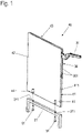
- FIG. 1 shows an isometric oblique view of a wall element 40 according to the application, in which a fitting 30 is integrated.
- the panel-shaped wall element 40 has a core 41, for example made from chipboard or from a medium or high-density fiberboard (MDF or HDF).
- the fitting 30 is arranged in the same plane as the core 41 and preferably with the same thickness, such that the core 41 and the fitting 30 complement one another in shape and size so that together they have the dimensions of the wall element 40 .
- the core 41 is formed in two parts and is divided in the plane of the lateral extent of the plate-shaped wall element 40 .
- a recess is introduced into each of the core halves, into which the fitting 30 is inserted.
- the core 41 or its two halves and the fitting 30 can be connected to one another via connecting elements that are not visible here, for example screws, clamps, pins, staples or the like.
- An adhesive connection can also be provided in addition to the connection elements mentioned or as the only connection.
- the core can also be made in one piece according to the invention with a recess into which the fitting 30 is inserted.
- Cover layers 42, 43 are applied, in particular glued or laminated, to the arrangement of the core 41 and the fitting 30 that is optionally connected thereto.
- the fitting 30 is selected with regard to its material and the material thickness, for example of side plates 301 of the fitting 30, so that it is not dented even during a laminating process, which could otherwise lead to an unevenness of the surface of the cover layers 42, 43. Smaller bumps in the side plates of the fitting 30 are compensated by the cover layers 42, 43. Such smaller bumps can, for example, be caused by bearing points of bolts that are used for the pivotable mounting of the lever mechanism 31 in the fitting 30 .
- the wall element 40 has connecting elements for connection to other furniture components.
- a U-shaped furniture leg 21 is shown as an example of such a further furniture component.
- threaded inserts 44 are concealed in the core 41 on a lower end face and serve as connecting elements for connecting the wall element 40 to the furniture leg 21 .
- Correspondingly positioned bores 211 are provided in the furniture leg 21 , through which screws 51 are guided, which are screwed into the threaded inserts 44 .
- the wall element 40 has all the necessary technical functional elements in order to be able to construct a piece of furniture even without an explicit furniture body.
- Figures 2a and 2b is a piece of furniture 10 according to the application, which has several of the 1 shown has wall elements 40 shown.
- Figure 2a shows the furniture in a partially assembled condition and Figure 2b then composed.
- the piece of furniture 10 comprises three wall elements 40, each with an integrated fitting 30, which are connected at their lower end face to a continuous sub-floor 22 as a furniture component.
- connecting elements integrated into the wall element 40 are used, for example those in 1 Threaded inserts 44 shown, into which screws (not visible here) are screwed.
- the boxes 23 are placed, which provide interior spaces of the piece of furniture 10 here by way of example. Since all technical functional elements such as the fitting 30 and the connecting elements are already contained in the wall elements 40, the boxes 23 can be designed freely with regard to the choice of material and can be made of glass, stone or metal, for example.
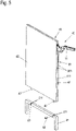
- FIG. 3 also shows an isometric representation of another example of a piece of furniture according to the application.
- two spaced and mutually parallel wall elements 40 are used, which in turn are similar to the example of FIG Fig. 2a, b placed on a sub-floor 22 and connected to it via the integrated connecting elements.
- the wall elements 40 also have comparable connecting elements on the opposite upper end face, via which they are connected to a top panel 24 placed on top.
- a shelf-like piece of furniture is created, the front surface of which can be closed entirely or in the area between the two wall elements 40 with a flap, not shown here.
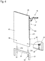
- Longitudinal bores 45 are introduced as fastening means from the lower end face into the core 41, which merge into transverse bores 46, which are introduced into a side surface of the wall element 40 from a cover layer (here the cover layer 42).
- Rotary connectors 53 are inserted into the transverse bores 46 and interact with bolts 52 which are inserted through the furniture foot 21 into the longitudinal bores 45 .
- the bolts 52 have heads, not shown in the figure, at their end, which are gripped by the rotary connectors 53 .
- the surfaces engaging behind the head are preferably formed eccentrically in the rotary connector 53, so that the bolt 52 is pulled into the wall element 40 and the furniture leg is pulled up against the wall element 40 accordingly.
- a resilient connection between the furniture leg 21 and the wall element 40 is thus achieved.
- pierced dowels 212 can be provided on the furniture leg 21, which are inserted into the longitudinal bore 45 and through which the bolts 52 are guided.
- connection element formed in the wall element 40 can be provided not only on the lower end face shown here as an example for connection to the furniture leg 21, but also on the upper and/or rear end face. It is also pointed out that the connection to the furniture leg 21 is purely exemplary.
- the in the Figures 4-6 The connecting elements shown can, for example, also be used to connect to the subfloor 22 or the top floor 24 in the exemplary embodiments of FIG Figures 2a, 2b and 3 be used.
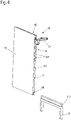
- a rotary connector 53 is also used in conjunction with a bolt, but in this case the rotary connector 53 is used in the furniture leg 21 in a corresponding bore 211.
- two bolts 47 are in turn arranged, for example, on the lower end face, which are inserted into the bore 211 of the furniture leg 21 and are fastened with the aid of the rotary connectors 53 .
- the bolts 47 can, for example, be provided with a thread and screwed into corresponding bores in the core 41 of the wall element 40 .
- a tongue and groove connection is provided between the wall element 40 and the further furniture component, here again by way of example a furniture leg 21 .
- a profile groove 48 is formed on the lower end face of the wall element 40, preferably over the entire width of the wall element 40, into which a correspondingly shaped profile strip 213, which is arranged or formed on the furniture leg 21, is inserted.
- the profile groove 48 has a keyhole-shaped or mushroom-shaped profile. It goes without saying that other undercut profiles such as a trapezoidal profile, a T-shaped profile or a Christmas tree profile can be used.
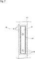
- FIG. 7 shows a front face 411 of a wall element 40 in the area of the fitting 30 in a top view.
- the edge band 49 is recessed. After the fitting 30 has been integrated, the edge band 49 is applied to the wall element 40 or to the front face 411 after the fitting 30 has been inserted into the wall element 40 .
- the edge band 49 is cut out in such a way that it partially rests on the fitting and, for example, covers the edges of the side plates 301 of the fitting 30 or other elements which are visible outside the opening of the fitting 30 .
- the outlines of the fitting 30 are indicated by dashed lines. Due to the arrangement of the edge band 49 on sections of the fitting 30, the fitting 30--apart from the extendable lever mechanism 31--is fully integrated into the wall element 40 and is no longer visible on its front face 411.
Landscapes
- Engineering & Computer Science (AREA)
- General Engineering & Computer Science (AREA)
- Mechanical Engineering (AREA)
- Furniture Connections (AREA)
- Assembled Shelves (AREA)
- Connection Of Plates (AREA)
- Cabinets, Racks, Or The Like Of Rigid Construction (AREA)
Claims (12)
- Élément de paroi (40) en forme de panneau pour un meuble (10), présentant au moins une ferrure intégrée (30) et au moins un élément d'assemblage intégré pour l'assemblage avec au moins un autre composant de meuble, lequel élément de paroi (40) en forme de panneau comporte au moins un élément central (41) fait de bois ou d'un matériau composite à base de bois, qui est disposé dans le même plan que la ferrure (30) et formé en une pièce avec un creux ou en deux parties séparées latéralement en deux moitiés d'élément central, dans lequel un creux est formé dans chacune des moitiés d'élément central pour recevoir la ferrure (30),dans lequel l'au moins un élément central (41) et la ferrure (30) sont disposés entre deux couches de couverture continues (42, 43), les deux couches de couverture continues (42, 43) étant assemblées à plat avec l'au moins un élément central (41) et/ou la ferrure (30), et dans lequel la ferrure (30) présente un mécanisme de levier (31) qui guide une partie de meuble mobile.
- Élément de paroi (40) selon la revendication 1, dans lequel l'au moins un élément d'assemblage est un insert fileté (44).
- Élément de paroi (40) selon la revendication 1 ou 2, dans lequel l'au moins un élément d'assemblage est une combinaison d'un trou longitudinal et d'un trou transversal (45, 46) destinée à recevoir un raccord tournant (53).
- Élément de paroi (40) selon l'une des revendications 1 à 3, dans lequel l'au moins un élément d'assemblage est une rainure profilée (48) ou une languette.
- Élément de paroi (40) selon l'une des revendications 1 à 4, dans lequel les deux couches de couverture continues (42, 43) sont stratifiées à plat sur l'au moins un élément central (41) et/ou sur la ferrure (30).
- Élément de paroi (40) selon l'une des revendications 1 à 5, dans lequel le mécanisme de levier (31) se trouve entièrement entre les couches de couverture (42, 43) quand la partie de meuble mobile est fermée.
- Meuble (10) avec au moins une ferrure (30) pour le guidage d'une partie de meuble mobile, comprenant au moins un élément de paroi (40) en forme de panneau selon l'une des revendications 1 à 6.
- Meuble (10) selon la revendication 7, comportant au moins un élément en forme de panneau comme autre composant de meuble, avec une surface qui repose par une face sur l'au moins un élément de paroi (40) en forme de panneau.
- Meuble (10) selon la revendication 8, dans lequel l'au moins un élément en forme de panneau est un fond inférieur et/ou un fond supérieur (22, 24).
- Meuble (10) selon la revendication 9, dans lequel au moins deux éléments de paroi (40) en forme de panneau sont disposés parallèlement et à distance l'un de l'autre.
- Meuble (10) selon la revendication 10, dans lequel un coffret (23) est disposé entre les deux éléments de paroi (40) en forme de panneaux.
- Meuble (10) selon la revendication 9, dans lequel le fond inférieur et/ou le fond supérieur (22, 24) forment la largeur du meuble et au moins un élément de paroi (40) en forme de panneau est écarté de 10 cm d'une arête extérieure du fond inférieur et/ou du fond supérieur (22, 24).
Applications Claiming Priority (2)
| Application Number | Priority Date | Filing Date | Title |
|---|---|---|---|
| DE102017104183.4A DE102017104183A1 (de) | 2017-02-28 | 2017-02-28 | Möbel und Wandelement für ein Möbel |
| PCT/EP2018/054531 WO2018158153A1 (fr) | 2017-02-28 | 2018-02-23 | Meuble et élément de paroi pour un meuble |
Publications (2)
| Publication Number | Publication Date |
|---|---|
| EP3589161A1 EP3589161A1 (fr) | 2020-01-08 |
| EP3589161B1 true EP3589161B1 (fr) | 2022-03-30 |
Family
ID=61557258
Family Applications (1)
| Application Number | Title | Priority Date | Filing Date |
|---|---|---|---|
| EP18708374.6A Active EP3589161B1 (fr) | 2017-02-28 | 2018-02-23 | Meuble et élément de paroi pour un meuble |
Country Status (6)
| Country | Link |
|---|---|
| US (1) | US10881207B2 (fr) |
| EP (1) | EP3589161B1 (fr) |
| CN (1) | CN110520012B (fr) |
| DE (1) | DE102017104183A1 (fr) |
| PL (1) | PL3589161T3 (fr) |
| WO (1) | WO2018158153A1 (fr) |
Families Citing this family (9)
| Publication number | Priority date | Publication date | Assignee | Title |
|---|---|---|---|---|
| DE102017104170A1 (de) * | 2017-02-28 | 2018-08-30 | ambigence GmbH & Co. KG | Wand eines Möbelkorpus, Verfahren zur Herstellung einer solchen Wand und Möbelkorpus oder Möbel mit einer solchen Wand |
| DE102017104185A1 (de) * | 2017-02-28 | 2018-08-30 | ambigence GmbH & Co. KG | Bauplatte für eine Möbelwand, Verfahren zur Herstellung einer solchen Bauplatte und einer Möbelwand sowie Möbelkorpus oder Möbel mit einer Möbelwand |
| DE102017126367A1 (de) * | 2017-11-10 | 2019-05-16 | Hettich-Oni Gmbh & Co. Kg | Klappenbeschlag für ein Möbel, Seitenwand eines Möbelkorpus und Möbel mit einer Seitenwand |
| ES2886502T3 (es) * | 2018-05-17 | 2021-12-20 | Kesseboehmer Holding Kg | Herraje de tapa para la fijación pivotante de una tapa de mueble a una carcasa de mueble |
| DE102018119539A1 (de) * | 2018-08-10 | 2020-02-13 | ambigence GmbH & Co. KG | Wand für ein Möbel, Verfahren zur Herstellung einer solchen Wand und Möbelkorpus oder Möbel mit einer solchen Wand |
| DE102019102491A1 (de) * | 2019-01-31 | 2020-08-06 | Hettich-Oni Gmbh & Co. Kg | Klappenbeschlag für ein Möbel |
| AT522656A1 (de) * | 2019-05-17 | 2020-12-15 | Blum Gmbh Julius | Möbelantrieb |
| AT524025B1 (de) * | 2020-09-14 | 2022-02-15 | Blum Gmbh Julius | Wand für einen Möbelkorpus und Verfahren zu deren Herstellung |
| USD1003730S1 (en) * | 2020-12-11 | 2023-11-07 | Julius Blum Gmbh | Wall furniture and element |
Family Cites Families (29)
| Publication number | Priority date | Publication date | Assignee | Title |
|---|---|---|---|---|
| US2360451A (en) | 1942-06-02 | 1944-10-17 | Stone Abraham | Collapsible clothing container |
| US3023910A (en) | 1957-01-24 | 1962-03-06 | Shirley E Schless | Support for sliding shelves |
| DE1867127U (de) | 1962-05-24 | 1963-02-14 | Fritz Schroeder K G Moebelwerk | Einbauwand. |
| DE1900741U (de) | 1964-04-25 | 1964-09-17 | Wilhelm Broelhorst & Co | Spuelkastenunterbau. |
| DE1559963A1 (de) | 1966-12-21 | 1969-12-18 | Ernst Maurmann Kg | Scharnier fuer Tueren bzw. Klappen u.dgl.,vorzugsweise an Moebeln |
| US3951558A (en) * | 1974-11-22 | 1976-04-20 | Komarov Anatoli N | Apparatus for demountably coupling two members |
| IT1028807B (it) | 1975-04-23 | 1979-02-10 | Sts Societa Toscana Semilavo R | Struttura ad elementi componibili, per l formazione di mobili scaffalature, rivestimenti ed altro |
| ES227935Y (es) | 1977-04-20 | 1977-11-16 | Modulo fijador para la sustentacion de bandejas. | |
| US4108514A (en) | 1977-10-18 | 1978-08-22 | Dual Gebruder Steidinger | Phonostand |
| US5720547A (en) * | 1995-07-11 | 1998-02-24 | Baird; Merrill F. | Modular storage bins |
| US7959242B2 (en) | 2003-06-02 | 2011-06-14 | Accuride International Inc. | Pocket door cabinet and slide assembly |
| US8641155B2 (en) * | 2007-07-26 | 2014-02-04 | David Lee | Modular furniture system |
| DE202009004805U1 (de) | 2009-05-12 | 2010-09-23 | Hettich Holding Gmbh & Co. Ohg | Möbelwand und Möbel |
| DE202009004806U1 (de) | 2009-05-12 | 2010-10-14 | Hettich Holding Gmbh & Co. Ohg | Möbel |
| CN202179292U (zh) * | 2011-08-02 | 2012-04-04 | 广州市卓明建材有限公司 | 无缝免焊接不锈钢柜体组装结构 |
| DE102013100481B4 (de) * | 2013-01-17 | 2015-08-06 | Wolfgang Fünfgeld | Baukastensystem, insbesondere für Möbel, Messeaufbauten oder dergleichen und Möbelstück oder Messeaufbau |
| DE202013003189U1 (de) | 2013-04-08 | 2014-07-10 | Grass Gmbh & Co. Kg | Wandelement für einen Möbelkorpus mit einer Korpuswand |
| JP2015181755A (ja) | 2014-03-25 | 2015-10-22 | 卓也 前川 | 組立式家具 |
| IL231941A (en) * | 2014-04-03 | 2015-07-30 | Oren Sitton | Printable and bending boards, structures containing them and methods for making them |
| DE102014109712B4 (de) * | 2014-07-10 | 2017-10-19 | Nobilia-Werke J.Stickling Gmbh & Co.Kg | Schrankmöbel und Verfahren zur Montage eines Schrankmöbels |
| US9386847B1 (en) | 2014-07-17 | 2016-07-12 | Austin Hardware And Supply, Inc. | Mounting system |
| DE202014105730U1 (de) | 2014-11-27 | 2016-03-02 | Grass Gmbh & Co. Kg | Wandelement eines Möbels und Möbel mit einem solchen Wandelement |
| DE112016002863A5 (de) * | 2015-06-26 | 2018-03-15 | Lutz Dönhoff | Verbindungsystem zum Zusammensetzen eines modularen Raumsystems |
| DE102015113427A1 (de) * | 2015-08-14 | 2017-02-16 | Form Orange Produktentwicklung | Wandschrank, insbesondere Küchen-Wandschrank |
| DE102017104171A1 (de) * | 2017-02-28 | 2018-08-30 | ambigence GmbH & Co. KG | Wand für einen Möbelkorpus, Verfahren zur Herstellung einer solchen Wand und Möbelkorpus oder Möbel mit einer solchen Wand |
| DE102017104182A1 (de) * | 2017-02-28 | 2018-08-30 | ambigence GmbH & Co. KG | Möbel |
| DE102017104170A1 (de) * | 2017-02-28 | 2018-08-30 | ambigence GmbH & Co. KG | Wand eines Möbelkorpus, Verfahren zur Herstellung einer solchen Wand und Möbelkorpus oder Möbel mit einer solchen Wand |
| DE102017104169A1 (de) * | 2017-02-28 | 2018-08-30 | ambigence GmbH & Co. KG | Wand eines Möbelkorpus, Verfahren zur Herstellung einer solchen Wand und Möbelkorpus oder Möbel mit einer solchen Wand |
| DE202018102089U1 (de) * | 2018-04-17 | 2019-07-18 | Grass Gmbh | Vorrichtung zur Bewegung eines an einem Möbelkorpus eines Möbels aufgenommenen Möbelteils |
-
2017
- 2017-02-28 DE DE102017104183.4A patent/DE102017104183A1/de not_active Withdrawn
-
2018
- 2018-02-23 US US16/489,174 patent/US10881207B2/en active Active
- 2018-02-23 CN CN201880014628.3A patent/CN110520012B/zh active Active
- 2018-02-23 EP EP18708374.6A patent/EP3589161B1/fr active Active
- 2018-02-23 WO PCT/EP2018/054531 patent/WO2018158153A1/fr unknown
- 2018-02-23 PL PL18708374.6T patent/PL3589161T3/pl unknown
Non-Patent Citations (1)
| Title |
|---|
| None * |
Also Published As
| Publication number | Publication date |
|---|---|
| CN110520012A (zh) | 2019-11-29 |
| WO2018158153A1 (fr) | 2018-09-07 |
| US20190380494A1 (en) | 2019-12-19 |
| CN110520012B (zh) | 2022-07-12 |
| PL3589161T3 (pl) | 2022-08-08 |
| DE102017104183A1 (de) | 2018-08-30 |
| EP3589161A1 (fr) | 2020-01-08 |
| US10881207B2 (en) | 2021-01-05 |
Similar Documents
| Publication | Publication Date | Title |
|---|---|---|
| EP3589161B1 (fr) | Meuble et élément de paroi pour un meuble | |
| EP3589165B1 (fr) | Paroi pour un corps de meuble, procédé pour la fabrication d'une telle paroi et corps de meuble ou meuble avec une telle paroi | |
| EP3589163B1 (fr) | Paroi d'un corps de meuble, procédé de fabrication d'une telle paroi et corps de meuble ou meuble doté d'une telle paroi | |
| EP3589164B1 (fr) | Paroi d'un corps de meuble, procédé de fabrication d'une telle paroi et corps de meuble ou meuble doté d'une telle paroi | |
| EP3589811B1 (fr) | Meuble comprenant un élément composite en forme de panneau démontable pourvu d'une ferrure intégrée | |
| EP3735152B1 (fr) | Ensemble d'un panneau de meuble et d'une ferrure de déplacement avec élément de montage intégré pour le panneau mobile, le corps du meuble et les meubles comprenant un tel panneau de meuble | |
| EP3589160B1 (fr) | Paroi d'un corps de meuble et corps de meuble ou meuble doté d'une telle paroi | |
| EP3589166A2 (fr) | Panneau de construction pour paroi de meuble, procédé de fabrication d'un tel panneau de construction et d'une paroi de meuble et corps de meuble ou meuble pourvu d'une paroi de meuble | |
| CH696889A5 (de) | Verriegelungselement und Verfahren zur Verriegelung von zwei Platten. | |
| EP3833222A1 (fr) | Paroi pour un meuble, procédé de fabrication d'une telle paroi et corps de meuble ou meuble doté d'une telle paroi | |
| EP3589162B1 (fr) | Meuble comprenant un élément rapporté extérieur pourvu d'une ferrure intégrée | |
| EP2039841A1 (fr) | Armoire ou étagère | |
| EP3115521B1 (fr) | Armature et systeme d'armature destine a la liaison reversible d'elements plats et systeme de paroi verticale modulaire | |
| EP2147778B1 (fr) | Plaque de construction légère pour la construction de meubles | |
| WO2018158156A1 (fr) | Paroi d'un corps de meuble et corps de meuble ou meuble doté d'une telle paroi | |
| AT412412B (de) | Adapterprofil | |
| DE102017104176A1 (de) | Möbelkorpus und Möbel | |
| EP4289310A1 (fr) | Élément de montage pour stocker des objets dans une cloison de construction sèche et agencement doté de celui-ci | |
| DE102022131160A1 (de) | Einbauelement zur Aufbewahrung von Gegenständen in einer Trockenbauwand und Anordnung hiermit | |
| DE102017104186A1 (de) | Wandeinbaumöbel | |
| DE102017104175A1 (de) | Wandeinbaumöbel und Bauelement für ein Wandeinbaumöbel | |
| DE2912582A1 (de) | Aus bauelementen aufgebaute schrankstruktur |
Legal Events
| Date | Code | Title | Description |
|---|---|---|---|
| STAA | Information on the status of an ep patent application or granted ep patent |
Free format text: STATUS: UNKNOWN |
|
| STAA | Information on the status of an ep patent application or granted ep patent |
Free format text: STATUS: THE INTERNATIONAL PUBLICATION HAS BEEN MADE |
|
| PUAI | Public reference made under article 153(3) epc to a published international application that has entered the european phase |
Free format text: ORIGINAL CODE: 0009012 |
|
| STAA | Information on the status of an ep patent application or granted ep patent |
Free format text: STATUS: REQUEST FOR EXAMINATION WAS MADE |
|
| 17P | Request for examination filed |
Effective date: 20190923 |
|
| AK | Designated contracting states |
Kind code of ref document: A1 Designated state(s): AL AT BE BG CH CY CZ DE DK EE ES FI FR GB GR HR HU IE IS IT LI LT LU LV MC MK MT NL NO PL PT RO RS SE SI SK SM TR |
|
| AX | Request for extension of the european patent |
Extension state: BA ME |
|
| DAV | Request for validation of the european patent (deleted) | ||
| DAX | Request for extension of the european patent (deleted) | ||
| STAA | Information on the status of an ep patent application or granted ep patent |
Free format text: STATUS: EXAMINATION IS IN PROGRESS |
|
| 17Q | First examination report despatched |
Effective date: 20200728 |
|
| STAA | Information on the status of an ep patent application or granted ep patent |
Free format text: STATUS: EXAMINATION IS IN PROGRESS |
|
| RAP3 | Party data changed (applicant data changed or rights of an application transferred) |
Owner name: AMBIGENCE GMBH & CO. KG |
|
| GRAP | Despatch of communication of intention to grant a patent |
Free format text: ORIGINAL CODE: EPIDOSNIGR1 |
|
| STAA | Information on the status of an ep patent application or granted ep patent |
Free format text: STATUS: GRANT OF PATENT IS INTENDED |
|
| INTG | Intention to grant announced |
Effective date: 20210924 |
|
| GRAS | Grant fee paid |
Free format text: ORIGINAL CODE: EPIDOSNIGR3 |
|
| GRAA | (expected) grant |
Free format text: ORIGINAL CODE: 0009210 |
|
| STAA | Information on the status of an ep patent application or granted ep patent |
Free format text: STATUS: THE PATENT HAS BEEN GRANTED |
|
| AK | Designated contracting states |
Kind code of ref document: B1 Designated state(s): AL AT BE BG CH CY CZ DE DK EE ES FI FR GB GR HR HU IE IS IT LI LT LU LV MC MK MT NL NO PL PT RO RS SE SI SK SM TR |
|
| REG | Reference to a national code |
Ref country code: GB Ref legal event code: FG4D Free format text: NOT ENGLISH |
|
| REG | Reference to a national code |
Ref country code: CH Ref legal event code: EP |
|
| REG | Reference to a national code |
Ref country code: DE Ref legal event code: R096 Ref document number: 502018009247 Country of ref document: DE |
|
| REG | Reference to a national code |
Ref country code: AT Ref legal event code: REF Ref document number: 1478412 Country of ref document: AT Kind code of ref document: T Effective date: 20220415 |
|
| REG | Reference to a national code |
Ref country code: IE Ref legal event code: FG4D Free format text: LANGUAGE OF EP DOCUMENT: GERMAN |
|
| REG | Reference to a national code |
Ref country code: LT Ref legal event code: MG9D |
|
| PG25 | Lapsed in a contracting state [announced via postgrant information from national office to epo] |
Ref country code: SE Free format text: LAPSE BECAUSE OF FAILURE TO SUBMIT A TRANSLATION OF THE DESCRIPTION OR TO PAY THE FEE WITHIN THE PRESCRIBED TIME-LIMIT Effective date: 20220330 Ref country code: RS Free format text: LAPSE BECAUSE OF FAILURE TO SUBMIT A TRANSLATION OF THE DESCRIPTION OR TO PAY THE FEE WITHIN THE PRESCRIBED TIME-LIMIT Effective date: 20220330 Ref country code: NO Free format text: LAPSE BECAUSE OF FAILURE TO SUBMIT A TRANSLATION OF THE DESCRIPTION OR TO PAY THE FEE WITHIN THE PRESCRIBED TIME-LIMIT Effective date: 20220630 Ref country code: LT Free format text: LAPSE BECAUSE OF FAILURE TO SUBMIT A TRANSLATION OF THE DESCRIPTION OR TO PAY THE FEE WITHIN THE PRESCRIBED TIME-LIMIT Effective date: 20220330 Ref country code: HR Free format text: LAPSE BECAUSE OF FAILURE TO SUBMIT A TRANSLATION OF THE DESCRIPTION OR TO PAY THE FEE WITHIN THE PRESCRIBED TIME-LIMIT Effective date: 20220330 Ref country code: BG Free format text: LAPSE BECAUSE OF FAILURE TO SUBMIT A TRANSLATION OF THE DESCRIPTION OR TO PAY THE FEE WITHIN THE PRESCRIBED TIME-LIMIT Effective date: 20220630 |
|
| REG | Reference to a national code |
Ref country code: NL Ref legal event code: MP Effective date: 20220330 |
|
| PG25 | Lapsed in a contracting state [announced via postgrant information from national office to epo] |
Ref country code: LV Free format text: LAPSE BECAUSE OF FAILURE TO SUBMIT A TRANSLATION OF THE DESCRIPTION OR TO PAY THE FEE WITHIN THE PRESCRIBED TIME-LIMIT Effective date: 20220330 Ref country code: GR Free format text: LAPSE BECAUSE OF FAILURE TO SUBMIT A TRANSLATION OF THE DESCRIPTION OR TO PAY THE FEE WITHIN THE PRESCRIBED TIME-LIMIT Effective date: 20220701 Ref country code: FI Free format text: LAPSE BECAUSE OF FAILURE TO SUBMIT A TRANSLATION OF THE DESCRIPTION OR TO PAY THE FEE WITHIN THE PRESCRIBED TIME-LIMIT Effective date: 20220330 |
|
| PG25 | Lapsed in a contracting state [announced via postgrant information from national office to epo] |
Ref country code: NL Free format text: LAPSE BECAUSE OF FAILURE TO SUBMIT A TRANSLATION OF THE DESCRIPTION OR TO PAY THE FEE WITHIN THE PRESCRIBED TIME-LIMIT Effective date: 20220330 |
|
| PG25 | Lapsed in a contracting state [announced via postgrant information from national office to epo] |
Ref country code: SM Free format text: LAPSE BECAUSE OF FAILURE TO SUBMIT A TRANSLATION OF THE DESCRIPTION OR TO PAY THE FEE WITHIN THE PRESCRIBED TIME-LIMIT Effective date: 20220330 Ref country code: SK Free format text: LAPSE BECAUSE OF FAILURE TO SUBMIT A TRANSLATION OF THE DESCRIPTION OR TO PAY THE FEE WITHIN THE PRESCRIBED TIME-LIMIT Effective date: 20220330 Ref country code: RO Free format text: LAPSE BECAUSE OF FAILURE TO SUBMIT A TRANSLATION OF THE DESCRIPTION OR TO PAY THE FEE WITHIN THE PRESCRIBED TIME-LIMIT Effective date: 20220330 Ref country code: PT Free format text: LAPSE BECAUSE OF FAILURE TO SUBMIT A TRANSLATION OF THE DESCRIPTION OR TO PAY THE FEE WITHIN THE PRESCRIBED TIME-LIMIT Effective date: 20220801 Ref country code: ES Free format text: LAPSE BECAUSE OF FAILURE TO SUBMIT A TRANSLATION OF THE DESCRIPTION OR TO PAY THE FEE WITHIN THE PRESCRIBED TIME-LIMIT Effective date: 20220330 Ref country code: EE Free format text: LAPSE BECAUSE OF FAILURE TO SUBMIT A TRANSLATION OF THE DESCRIPTION OR TO PAY THE FEE WITHIN THE PRESCRIBED TIME-LIMIT Effective date: 20220330 Ref country code: CZ Free format text: LAPSE BECAUSE OF FAILURE TO SUBMIT A TRANSLATION OF THE DESCRIPTION OR TO PAY THE FEE WITHIN THE PRESCRIBED TIME-LIMIT Effective date: 20220330 |
|
| PG25 | Lapsed in a contracting state [announced via postgrant information from national office to epo] |
Ref country code: IS Free format text: LAPSE BECAUSE OF FAILURE TO SUBMIT A TRANSLATION OF THE DESCRIPTION OR TO PAY THE FEE WITHIN THE PRESCRIBED TIME-LIMIT Effective date: 20220730 Ref country code: AL Free format text: LAPSE BECAUSE OF FAILURE TO SUBMIT A TRANSLATION OF THE DESCRIPTION OR TO PAY THE FEE WITHIN THE PRESCRIBED TIME-LIMIT Effective date: 20220330 |
|
| REG | Reference to a national code |
Ref country code: DE Ref legal event code: R097 Ref document number: 502018009247 Country of ref document: DE |
|
| PG25 | Lapsed in a contracting state [announced via postgrant information from national office to epo] |
Ref country code: DK Free format text: LAPSE BECAUSE OF FAILURE TO SUBMIT A TRANSLATION OF THE DESCRIPTION OR TO PAY THE FEE WITHIN THE PRESCRIBED TIME-LIMIT Effective date: 20220330 |
|
| PLBE | No opposition filed within time limit |
Free format text: ORIGINAL CODE: 0009261 |
|
| STAA | Information on the status of an ep patent application or granted ep patent |
Free format text: STATUS: NO OPPOSITION FILED WITHIN TIME LIMIT |
|
| 26N | No opposition filed |
Effective date: 20230103 |
|
| PGFP | Annual fee paid to national office [announced via postgrant information from national office to epo] |
Ref country code: AT Payment date: 20230215 Year of fee payment: 6 |
|
| PG25 | Lapsed in a contracting state [announced via postgrant information from national office to epo] |
Ref country code: SI Free format text: LAPSE BECAUSE OF FAILURE TO SUBMIT A TRANSLATION OF THE DESCRIPTION OR TO PAY THE FEE WITHIN THE PRESCRIBED TIME-LIMIT Effective date: 20220330 |
|
| PGFP | Annual fee paid to national office [announced via postgrant information from national office to epo] |
Ref country code: TR Payment date: 20230222 Year of fee payment: 6 Ref country code: PL Payment date: 20230213 Year of fee payment: 6 Ref country code: IT Payment date: 20230228 Year of fee payment: 6 Ref country code: DE Payment date: 20230216 Year of fee payment: 6 |
|
| P01 | Opt-out of the competence of the unified patent court (upc) registered |
Effective date: 20230402 |
|
| PG25 | Lapsed in a contracting state [announced via postgrant information from national office to epo] |
Ref country code: MC Free format text: LAPSE BECAUSE OF FAILURE TO SUBMIT A TRANSLATION OF THE DESCRIPTION OR TO PAY THE FEE WITHIN THE PRESCRIBED TIME-LIMIT Effective date: 20220330 |
|
| REG | Reference to a national code |
Ref country code: CH Ref legal event code: PL |
|
| REG | Reference to a national code |
Ref country code: BE Ref legal event code: MM Effective date: 20230228 |
|
| GBPC | Gb: european patent ceased through non-payment of renewal fee |
Effective date: 20230223 |
|
| PG25 | Lapsed in a contracting state [announced via postgrant information from national office to epo] |
Ref country code: LI Free format text: LAPSE BECAUSE OF NON-PAYMENT OF DUE FEES Effective date: 20230228 Ref country code: CH Free format text: LAPSE BECAUSE OF NON-PAYMENT OF DUE FEES Effective date: 20230228 Ref country code: LU Free format text: LAPSE BECAUSE OF NON-PAYMENT OF DUE FEES Effective date: 20230223 |
|
| REG | Reference to a national code |
Ref country code: IE Ref legal event code: MM4A |
|
| PG25 | Lapsed in a contracting state [announced via postgrant information from national office to epo] |
Ref country code: GB Free format text: LAPSE BECAUSE OF NON-PAYMENT OF DUE FEES Effective date: 20230223 |
|
| PG25 | Lapsed in a contracting state [announced via postgrant information from national office to epo] |
Ref country code: IE Free format text: LAPSE BECAUSE OF NON-PAYMENT OF DUE FEES Effective date: 20230223 Ref country code: GB Free format text: LAPSE BECAUSE OF NON-PAYMENT OF DUE FEES Effective date: 20230223 Ref country code: FR Free format text: LAPSE BECAUSE OF NON-PAYMENT OF DUE FEES Effective date: 20230228 |
|
| PG25 | Lapsed in a contracting state [announced via postgrant information from national office to epo] |
Ref country code: BE Free format text: LAPSE BECAUSE OF NON-PAYMENT OF DUE FEES Effective date: 20230228 |
|
| PGFP | Annual fee paid to national office [announced via postgrant information from national office to epo] |
Ref country code: AT Payment date: 20240216 Year of fee payment: 7 |
|
| PGFP | Annual fee paid to national office [announced via postgrant information from national office to epo] |
Ref country code: DE Payment date: 20240216 Year of fee payment: 7 |