EP3588681A1 - Borne de connexion de conducteur - Google Patents
Borne de connexion de conducteur Download PDFInfo
- Publication number
- EP3588681A1 EP3588681A1 EP19192347.3A EP19192347A EP3588681A1 EP 3588681 A1 EP3588681 A1 EP 3588681A1 EP 19192347 A EP19192347 A EP 19192347A EP 3588681 A1 EP3588681 A1 EP 3588681A1
- Authority
- EP
- European Patent Office
- Prior art keywords
- spring
- actuating element
- insulating material
- terminal
- conductor
- Prior art date
- Legal status (The legal status is an assumption and is not a legal conclusion. Google has not performed a legal analysis and makes no representation as to the accuracy of the status listed.)
- Pending
Links
- 239000004020 conductor Substances 0.000 title claims abstract description 91
- 239000011810 insulating material Substances 0.000 claims abstract description 76
- 238000003780 insertion Methods 0.000 description 31
- 230000037431 insertion Effects 0.000 description 31
- 239000000463 material Substances 0.000 description 2
- 239000011324 bead Substances 0.000 description 1
- 238000005452 bending Methods 0.000 description 1
- 230000005540 biological transmission Effects 0.000 description 1
- 238000010276 construction Methods 0.000 description 1
- 239000000523 sample Substances 0.000 description 1
- 230000007704 transition Effects 0.000 description 1
Images


Classifications
-
- H—ELECTRICITY
- H01—ELECTRIC ELEMENTS
- H01R—ELECTRICALLY-CONDUCTIVE CONNECTIONS; STRUCTURAL ASSOCIATIONS OF A PLURALITY OF MUTUALLY-INSULATED ELECTRICAL CONNECTING ELEMENTS; COUPLING DEVICES; CURRENT COLLECTORS
- H01R4/00—Electrically-conductive connections between two or more conductive members in direct contact, i.e. touching one another; Means for effecting or maintaining such contact; Electrically-conductive connections having two or more spaced connecting locations for conductors and using contact members penetrating insulation
- H01R4/28—Clamped connections, spring connections
- H01R4/48—Clamped connections, spring connections utilising a spring, clip, or other resilient member
-
- H—ELECTRICITY
- H01—ELECTRIC ELEMENTS
- H01R—ELECTRICALLY-CONDUCTIVE CONNECTIONS; STRUCTURAL ASSOCIATIONS OF A PLURALITY OF MUTUALLY-INSULATED ELECTRICAL CONNECTING ELEMENTS; COUPLING DEVICES; CURRENT COLLECTORS
- H01R4/00—Electrically-conductive connections between two or more conductive members in direct contact, i.e. touching one another; Means for effecting or maintaining such contact; Electrically-conductive connections having two or more spaced connecting locations for conductors and using contact members penetrating insulation
- H01R4/28—Clamped connections, spring connections
- H01R4/50—Clamped connections, spring connections utilising a cam, wedge, cone or ball also combined with a screw
- H01R4/5066—Clamped connections, spring connections utilising a cam, wedge, cone or ball also combined with a screw mounted in an insulating housing having a cover providing clamping force
-
- H—ELECTRICITY
- H01—ELECTRIC ELEMENTS
- H01R—ELECTRICALLY-CONDUCTIVE CONNECTIONS; STRUCTURAL ASSOCIATIONS OF A PLURALITY OF MUTUALLY-INSULATED ELECTRICAL CONNECTING ELEMENTS; COUPLING DEVICES; CURRENT COLLECTORS
- H01R4/00—Electrically-conductive connections between two or more conductive members in direct contact, i.e. touching one another; Means for effecting or maintaining such contact; Electrically-conductive connections having two or more spaced connecting locations for conductors and using contact members penetrating insulation
- H01R4/28—Clamped connections, spring connections
- H01R4/48—Clamped connections, spring connections utilising a spring, clip, or other resilient member
- H01R4/4809—Clamped connections, spring connections utilising a spring, clip, or other resilient member using a leaf spring to bias the conductor toward the busbar
- H01R4/48185—Clamped connections, spring connections utilising a spring, clip, or other resilient member using a leaf spring to bias the conductor toward the busbar adapted for axial insertion of a wire end
- H01R4/4819—Clamped connections, spring connections utilising a spring, clip, or other resilient member using a leaf spring to bias the conductor toward the busbar adapted for axial insertion of a wire end the spring shape allowing insertion of the conductor end when the spring is unbiased
- H01R4/4821—Single-blade spring
-
- H—ELECTRICITY
- H01—ELECTRIC ELEMENTS
- H01R—ELECTRICALLY-CONDUCTIVE CONNECTIONS; STRUCTURAL ASSOCIATIONS OF A PLURALITY OF MUTUALLY-INSULATED ELECTRICAL CONNECTING ELEMENTS; COUPLING DEVICES; CURRENT COLLECTORS
- H01R4/00—Electrically-conductive connections between two or more conductive members in direct contact, i.e. touching one another; Means for effecting or maintaining such contact; Electrically-conductive connections having two or more spaced connecting locations for conductors and using contact members penetrating insulation
- H01R4/28—Clamped connections, spring connections
- H01R4/48—Clamped connections, spring connections utilising a spring, clip, or other resilient member
- H01R4/4809—Clamped connections, spring connections utilising a spring, clip, or other resilient member using a leaf spring to bias the conductor toward the busbar
- H01R4/4828—Spring-activating arrangements mounted on or integrally formed with the spring housing
- H01R4/483—Pivoting arrangements, e.g. lever pushing on the spring
-
- H—ELECTRICITY
- H01—ELECTRIC ELEMENTS
- H01R—ELECTRICALLY-CONDUCTIVE CONNECTIONS; STRUCTURAL ASSOCIATIONS OF A PLURALITY OF MUTUALLY-INSULATED ELECTRICAL CONNECTING ELEMENTS; COUPLING DEVICES; CURRENT COLLECTORS
- H01R12/00—Structural associations of a plurality of mutually-insulated electrical connecting elements, specially adapted for printed circuits, e.g. printed circuit boards [PCB], flat or ribbon cables, or like generally planar structures, e.g. terminal strips, terminal blocks; Coupling devices specially adapted for printed circuits, flat or ribbon cables, or like generally planar structures; Terminals specially adapted for contact with, or insertion into, printed circuits, flat or ribbon cables, or like generally planar structures
- H01R12/70—Coupling devices
- H01R12/82—Coupling devices connected with low or zero insertion force
- H01R12/85—Coupling devices connected with low or zero insertion force contact pressure producing means, contacts activated after insertion of printed circuits or like structures
- H01R12/88—Coupling devices connected with low or zero insertion force contact pressure producing means, contacts activated after insertion of printed circuits or like structures acting manually by rotating or pivoting connector housing parts
-
- H—ELECTRICITY
- H01—ELECTRIC ELEMENTS
- H01R—ELECTRICALLY-CONDUCTIVE CONNECTIONS; STRUCTURAL ASSOCIATIONS OF A PLURALITY OF MUTUALLY-INSULATED ELECTRICAL CONNECTING ELEMENTS; COUPLING DEVICES; CURRENT COLLECTORS
- H01R4/00—Electrically-conductive connections between two or more conductive members in direct contact, i.e. touching one another; Means for effecting or maintaining such contact; Electrically-conductive connections having two or more spaced connecting locations for conductors and using contact members penetrating insulation
- H01R4/28—Clamped connections, spring connections
- H01R4/48—Clamped connections, spring connections utilising a spring, clip, or other resilient member
- H01R4/4809—Clamped connections, spring connections utilising a spring, clip, or other resilient member using a leaf spring to bias the conductor toward the busbar
- H01R4/4846—Busbar details
- H01R4/485—Single busbar common to multiple springs
Definitions
- the invention relates to a conductor connection terminal with an insulating material housing and with at least one spring-loaded terminal connection in the insulating material housing, and with at least one actuating element which is pivotally received in the insulating material housing and is designed to open at least one associated spring-loaded terminal connection.
- Such conductor connection terminals are known, for example, as lever-operated socket terminals. However, they can also be designed as a circuit board terminal, as a terminal block or as a conductor terminal in another electrical device.
- DE 102 37 701 B4 shows a lever-operated connecting terminal with a contact insert, which is formed from compact cage springs and a flat common busbar.
- a contact insert which is formed from compact cage springs and a flat common busbar.
- an associated actuating lever with pivot pin is pivotally received in the insulating material housing.
- the rear end of an actuating lever acts on the top of a cage tension spring in order to open the clamping point formed with the cage tension spring.
- a slot is provided on the underside of the actuating levers, which leads to an increase in the stiffness of the actuating lever formed from plastic material.
- WO 2010/133082 A1 shows a circuit board connection terminal with linearly displaceable actuating pushbuttons, which have a transverse web lying above the insulating material housing and adjoining spaced-apart side webs. The side webs plunge into the interior of the insulating material housing and interact with a U-shaped leaf spring to open a clamping point for an electrical conductor formed by a free clamping edge of the leaf spring and a busbar.
- a terminal with an insulating housing and at least one spring terminal unit has a clamping spring which can be actuated via an actuating section by pulling force against the spring force in order to open a clamping point.
- the pulling force is exerted by an actuating lever which is pivotably received in the insulating material housing and which is placed in a free space of the insulating material housing.
- the spring-loaded terminal connection is located directly below the actuating lever, which, however, is not accessible from the outside by a pivotable locking lever of the actuating element and the actuating lever interacting with it.
- the actuating element has two lever arm sections spaced apart from one another, which at least partially dip into the insulating material housing with a pivot bearing region and are connected to one another at a distance from the pivot bearing region with a transverse web to form a lever arm, that on the side of the insulating material housing on which the at least one actuating element is arranged, the at least one spring-loaded terminal connection is covered by an outer boundary wall of the insulating housing and extending from the outer boundary wall on both sides to a respectively assigned spring-loaded terminal connection side wall sections into the interior of the insulating material housing.
- one housing wall section of the insulating material housing projects into a free space of the respectively assigned actuating element which is adjacent to the crosspiece and which is laterally delimited by the lever arm sections.
- the design of the actuating element as a type of U-shaped bracket with two lever arm sections and a transverse web connecting these side wall sections provides a stable pivoting lever, the lever arm sections of which dip into the insulating material housing. Between the lever arm sections and the crosspiece, a free space, which is encompassed by the pivoting lever, is provided for receiving insulating material housing sections.
- the free space adjacent to the crosspiece is used to accommodate a housing wall section of the insulating material housing, without thereby increasing the size of the conductor connection terminal. With the help of the housing wall section protruding into the free space in the closed state, the air and creepage distances are significantly increased.
- the spring-loaded terminal connection can be covered at the top by the upper, outer boundary wall of the housing wall section.
- the housing wall sections can at least partially fill up the free space in the closed state of the associated actuating element.
- the actuating element In the open state of the actuating element, in which the actuating element is pivoted open counter to the spring force in order to open a clamping point formed by the spring-loaded terminal connection, the actuating element partially immerses into the interior of the insulating material housing.
- the housing wall section can be flush with the upper side of the adjacent section of the actuating element.
- the housing wall section can comprise an elevation.
- the housing wall section can be U-shaped in cross section.
- a pair of side wall sections which receive a spring-loaded terminal connection between them, can, together with the associated outer boundary wall, form a housing wall section of the insulating material housing with a U-shaped cross section.
- the length of the extension of the side wall sections into the interior of the insulating material housing essentially determines the clearance and creepage distance. Starting from the spring clamp connection, this acts along the inner wall over a free edge of the side wall section and along the outer wall.
- the side wall sections and their contribution to increasing the air and creepage distances are therefore not easy with inner and outer walls comparable to a closed insulating material housing. Rather, they interact with the lever arm sections of an associated actuating element.
- the free space provided by the swivel lever with its two lever arm sections spaced apart and partially protruding into the insulating material housing contributes to the compact design by accommodating the U-shaped housing wall section in the free space laterally delimited by the lever arm sections. At least in the swiveled-down state of the swivel lever, in which the clamping point formed by the at least one assigned spring-force clamping connection is closed, this free space is thus at least partially filled by sections of the insulating material housing projecting into the free space.
- the cross-sectionally U-shaped housing wall section for receiving the spring-loaded terminal connection with lateral limitation by the side wall sections has the further advantage that the spring-loaded terminal connection itself can at least partially dip into the space between the side wall sections.
- the clamping springs of the spring-loaded terminal connections can then be opened by means of suitable contours on the lever arm sections when the actuating element is pivoted.
- the power transmission through the lever from the crossbar via the lever arm sections to the clamping springs of the spring-loaded terminal connections is optimal, since the lever arm sections lie next to the clamping springs.
- the side wall sections which extend from the outer boundary wall into the interior of the insulating material housing and which lie laterally next to a spring-loaded terminal connection can end in a section (area) which extends parallel to at least part of the swivel bearing area of the associated actuating element, adjacent to this swivel bearing area.
- the side wall sections thus still ending at the level of the spring-loaded terminal connection thereby have an edge located in the interior of the insulating material housing. A sufficient clearance and creepage distance is ensured by the length of the side wall section extending into the interior of the insulating material housing.
- the lever arm sections of the actuating element can adjoin a respectively assigned side wall section lying laterally next to a spring-loaded terminal connection. This further increases the clearance and creepage distances with a compact design.
- the side wall sections can provide lateral guidance for a lever arm section of the actuating element when swiveling down in the outer region of the conductor connection terminal through the side wall of the insulating material housing and the housing wall section.
- a particularly compact and optimized conductor connection terminal can be achieved if the elevation is flush with the top of the adjacent section of the actuating element. In this way, the available height of the conductor terminal is optimally used.
- a section of an outer boundary wall of the insulating material housing can be arranged in the closed state of the respectively assigned actuating element directly below the crossbar of the assigned actuating element in a free space which is formed by the crossbar and adjoining lever arm sections.
- the in the volume of the swivel lever through the crossbar and the adjoining lever arm sections free space is thus at least partially filled in the closed state of the pivoting lever by a housing wall section of U-shaped cross section with its upper boundary wall of the insulating material housing and the side wall sections projecting into the interior of the insulating material housing.
- This free space is thus used to accommodate a housing wall section with a U-shaped cross section and thus to improve the clearance and creepage distances in a compact design.
- Such a space can also be used as a test opening.
- an air gap is opened between the outer boundary wall of the insulating material housing and an adjacent conductor insertion opening boundary wall to form a test opening on opposite sides, an adjacent spring clamp connection being accessible via the gap for a test tool guided through the test opening.
- At least one of the swivel bearing areas of the lever arm sections of the actuating elements can have an actuating contour that when pivoted of the actuating element can be brought into engagement with a clamping spring of an associated spring-loaded terminal connection in order to open a clamping point of the spring-loaded terminal connection formed by a clamping edge of the clamping spring and a busbar section of a busbar for connecting an electrical conductor.
- a clamping spring can be, for example, a leaf spring with a spring arch and adjoining leg on one side and adjoining leg on the other, the clamping leg having a free end region for forming a clamping edge.
- the actuating contour acts upon a pivoting of the actuating element, preferably a laterally projecting section of the clamping leg, in order in this way to move the clamping edge away from the busbar section.
- the busbar extends over at least two spring-loaded terminal connections arranged next to one another in a row in order to electrically and conductively connect electrical conductors connected to the at least two spring-loaded terminal connections.
- Fig. 1 shows a perspective view of a conductor terminal 1 in the form of a lever-operated socket terminal with an insulating material housing 2 and actuating elements 3 arranged next to one another.
- conductor insertion openings 4 are provided on the front side, via which respectively assigned spring-loaded terminal connections (not visible) are accessible for an electrical conductor inserted in a conductor insertion opening for clamping the same.
- a clamping spring of a spring-loaded clamping connection is acted upon by the actuating element 3 and a clamping point formed by the clamping spring and a busbar of the spring-loaded clamping connection for connecting or removing a clamped electrical Conductor opened.
- U-shaped housing wall sections 5 of an outer boundary wall of the insulating material housing 2 project into a free space 6 of an associated U-shaped actuating element 3 when the actuating element 3 is pivoted down. In the pivoted down, closed state of the associated actuating element 3, these U-shaped housing wall sections 5 fill the free space 6 at least partially.
- the U-shaped housing wall sections 5 are preferably flush on the upper side with the upper level of the insulating material housing 1 formed by the upper edge edges of the insulating material housing 2.
- “Upper” or “upper” is understood to mean the side of the conductor connecting terminal 1 on which the actuating elements 3 are arranged in the form of pivotable actuating levers.
- the actuating elements 3 have two lever arm sections 7a, 7b spaced apart from one another and a crossbar 8 connecting the two lever arm sections 7a, 7b to one another.
- the pivot axis for the pivot lever i.e. for the actuating element 3
- an actuating contour connected to a lever arm section for acting on a clamping spring of the spring-loaded terminal connection for opening a clamping point formed by the clamping spring.
- the embodiment of the actuating element 3 with two lever arm sections 7a, 7b spaced apart from one another, which plunge into the insulating material housing 2 and are pivotably mounted there, and the crossbar 8 connecting the two lever arm sections 7a, 7b to one another creates a very kink-stable pivoting lever which is extremely compact and is flat.
- the crossbar 8 offers a wide gripping surface in order to apply an actuating force for pivoting the actuating element 3 onto the pivot lever by hand or an actuating tool.
- Fig. 2 omits a side sectional view through the conductor terminal 1 Fig. 1 recognize in the area of an open actuator 3.
- the spring-loaded terminal connection 11 is also visible, which has a busbar 12 extending transversely to the conductor insertion direction L and a clamping spring 13.
- the clamping spring 13 is suspended with a contact leg 14 in the busbar 12.
- the busbar 12 has a holding section 15 which is angled upward in the direction of the actuating element 3 and has a recess 16 which enables an electrical conductor to be inserted.
- This recess 16 is delimited at the free end by a retaining web 17 on which the contact leg 14 of the clamping spring 13 abuts.
- the clamping spring 13 is thus fixed on the busbar 12 via the holding web 17.
- a spring arch 18 adjoins the contact leg 14, from which the clamping leg 19 extends with a clamping edge 20 at the free end. It becomes clear that the clamping leg 19 is bent in its end section at an angle of approximately 70 ° to 110 °, preferably approximately 85 ° to 95 °.
- the free end with the clamping edge 20 is then bent back in the conductor insertion direction.
- the section bent here by approximately 90 ° is transverse to the direction of insertion of the conductor, so that direct insertion of a multi-wire or finely-stranded electrical conductor without opening the clamping point by pivoting the actuating element 3 is prevented.
- the clamping leg 19 then forms a space by bending Recording the free stripped end of the inserted electrical conductor and merges into a spring arch 18 above the conductor insertion opening 4.
- a clamping leg 19 connects to the spring arch 18, the free end of the clamping leg 19 having a clamping edge 20.
- a clamping point for connecting an electrical conductor (not shown) is formed between the clamping edge 20 and the busbar 10.
- the busbar 12 is inclined with respect to the conductor insertion direction L defined by the direction of extension of the conductor insertion opening 4.
- the busbar 12 is inclined in particular relative to the upper conductor insertion opening boundary wall 9 and the front section of the opposite lower conductor insertion opening boundary wall by approximately 5 ° to 25 °. This provides a run-up slope for the electrical conductor and on the busbar 12 in the transition to the recess 16 a contact edge 21 is provided which, together with the clamping edge 20 of the clamping spring 13, forms a defined clamping point.
- lever arm section 7a plunges into the space enclosed by the insulating material housing 2 and is pivotably mounted in a part-circular bearing section 22 of the insulating material housing 2 with a pivot bearing region 23 of the lever arm section 7a.
- An actuating contour 24 is provided on this pivot bearing area 23, which interacts with an actuating tab (not visible) of the clamping arm 19 of the clamping spring 13 that projects laterally.
- the swivel bearing region 23 which is part-circular on the end face, is rotatably mounted on the part-circular bearing section 22.
- the pivot bearing area 23 is also on the busbar 12, which also contributes to the mounting of the actuating element 3.
- the insulating material housing 2 is formed in two parts.
- a rear cover part 25 is locked with a front housing part 26 by means of locking tabs and / or locking openings. After insertion of the actuating element 3 and the associated spring-loaded terminal connection 11 into the front housing part 26, the latter is closed by inserting and latching the rear cover part 25.
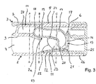
- Fig. 3 omits a side sectional view through the conductor terminal 1 Figure 1 recognize in the area of a closed actuating element 3. It is clear that the actuating element 3 with its crosspiece 8 is folded down in the direction of the insulating material housing 2, so that the crosspiece 8 directly adjoins an outer housing wall 10 of the insulating material housing 2.
- the actuating contour 24 is off compared to the open position Figure 2 rotated by approximately 80 to 90 ° in order to enable the clamping edge 20 to be displaced downward in the direction of the busbar 12 by the spring force of the clamping spring 13, so that when the electrical conductor is not clamped in the rest position shown, the clamping edge 20 is preferably still on the busbar by spring force 12 rests.
- the housing wall section 5 of the insulating material housing 2 which is U-shaped in cross-section, dips into the free space 6 of the actuating element 3 adjacent to the transverse web 8.
- the lever arm sections 7a, 7b below the crosspiece 8 which is also partially filled with part of the outer boundary wall 10 of the insulating material housing 2.
- This outer boundary wall 10 forms in the section shown an upper boundary wall for a space 27.
- the middle spring terminal connection 11 can, as from Figure 1 it can be seen that the front and rear end faces of the intermediate space 27 are open. In this way, the spring arch 18 of the clamping spring 13 is accessible from the outside via the intermediate space 27 and it is possible to measure the electrical potential at the spring-loaded terminal connection 9 with the aid of a test tool inserted into the test opening (voltage test probe or screwdriver with voltage potential display).
- the intermediate space 27 is delimited on the side opposite the outer boundary wall 10 by a conductor insertion opening boundary wall 9, to which the conductor insertion opening 4 is connected.
- Fig. 4 shows a cross-sectional view in section CC through the conductor terminal 1.
- the left actuating element 3 is open, while the actuating elements 3 lying to the right are closed.
- the viewing direction of the representation in Figure 4 corresponds to the conductor insertion opening L.
- the section CC goes through the pivot bearing area 23 of the levers on the section 7a, 7b. It is clear that on the two lever arm sections 7a, 7b in the pivot bearing area 23 mutually facing actuating pins 28 are arranged, each having an actuating contour 24.
- the actuating pins 28 are positioned below the clamping leg 19 of the associated clamping spring 13, to enable the clamping leg 19 in the direction of the contact leg 14 when the actuating lever 3 is pivoted from the closed position into the open position shown on the left.
- the housing wall section 5, which is U-shaped in cross section, is formed from a section of the outer boundary wall 10 and two side wall sections 29a, 29b projecting at a distance from one another in the direction of the interior of the insulating material housing 2.
- These side wall sections 29a, 29b laterally adjoin the assigned spring-force clamp connection 11 and partially take the assigned spring-force clamp connection 11 into the interior of the housing wall section 5, which is U-shaped in cross section.
- the spring-loaded terminal connection 11 is covered at the top by the upper, outer boundary wall 10 of the U-shaped housing wall section 5.
- the clearance and creepage distance of the conductor terminal 1 shown is defined by the shortest connection through the air or via the surface of the insulating material between the spring-loaded terminal connection 13 carrying voltage potential and the outside of the insulating material housing 2.
- the clearance and creepage distance runs along the side wall sections 29a of the U-shaped housing wall section 5.
- Fig. 5 shows a cross-sectional view in section BB through the conductor terminal 1.
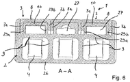
- Fig. 6 shows a cross-sectional view in section AA through the conductor terminal 1.
- the outer boundary wall 10 adjoining the intermediate space 27, with its side wall sections 29a, 29b projecting therefrom into the interior of the insulating material housing 2, defines a housing wall section 5 which is U-shaped in cross section and which is formed by the crossbar 8 and the lever arm sections 7a, 7b associated actuator 3 formed space 6 protrudes.
- the side wall sections 29a, 29b are integrally connected to the insulating walls which surround the conductor insertion openings 4 and thus define the conductor insertion openings 4.
- the side wall sections 29a, 29b merge into these wall sections of the conductor insertion openings 4.
- the side wall sections 29a, 29b provide lateral guidance for a lever arm section 7a, 7b of the actuating element 3 when swiveling down in the outer region of the conductor connecting terminal 1 through the side wall of the insulating material housing 2 and the projecting U-shaped housing wall section 5.
- the adjacent projecting U-shaped housing wall sections 5 provide an intermediate space for receiving two adjacent lever arm sections 7a, 7b of adjacent actuating elements 3.
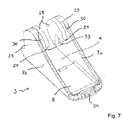
- Fig. 7 shows a perspective view of an actuating element 3 for the conductor terminal 1 described above from below.
- the basically U-shaped construction of the actuating lever can be seen, which is formed by two lever arm sections 7a, 7b arranged at a distance from one another and a crossbar 8 connecting them in the front region.
- the lever arm sections 7a, 7b taper in the direction of their free end or in the direction of the crosspiece 8. They are designed to be part-circular opposite the crosspiece 8 in order to provide a pivot bearing area by the actuating element 3 being pivotably mounted in the insulating material housing.
- this pivot bearing area 23 there is a part-circular actuation contour 24 with an actuation cutout 33 at an angle of approximately 90 ° (60 to 100 °).
- the actuating contour 24 is arranged at a distance from the adjoining associated lever arm section 7a, 7b by a free space 30, so that a side wall section 29a, 29b of the housing wall section 5 of U-shaped cross section of the insulating material housing 2 can dip into this free space 30 (see Figure 4 ).
- the actuating element 3 is thus not only guided over the part-circular end faces of the pivot bearing area 23 and the actuating pin 28 there and through the outer sides of the lever arm sections 7a, 7b, but can also be guided and passed through a side wall section 29a, 29b of the insulating material housing 2 projecting into the intermediate space 30 be stabilized.
- a material tab projecting laterally from a clamping spring 13 then projects into the actuating cutout 33 of the actuating contour 24 in order to open the clamping spring when the actuating element 3 is pivoted, as previously described.
- an actuating bead 34 is provided on the front end face of the crosspiece 8. This improves the gripping of the actuating element 3 by hand or with an actuating tool in order to pivot the actuating element 3.
Landscapes
- Connections Arranged To Contact A Plurality Of Conductors (AREA)
- Installation Of Indoor Wiring (AREA)
- Details Of Connecting Devices For Male And Female Coupling (AREA)
- Connections By Means Of Piercing Elements, Nuts, Or Screws (AREA)
- Clamps And Clips (AREA)
Applications Claiming Priority (3)
| Application Number | Priority Date | Filing Date | Title |
|---|---|---|---|
| DE102013101409.7A DE102013101409B4 (de) | 2013-02-13 | 2013-02-13 | Leiteranschlussklemme |
| EP14706795.3A EP2956995B1 (fr) | 2013-02-13 | 2014-02-12 | Borne de connexion de conducteur |
| PCT/EP2014/052717 WO2014124960A1 (fr) | 2013-02-13 | 2014-02-12 | Borne de connexion de conducteur |
Related Parent Applications (1)
| Application Number | Title | Priority Date | Filing Date |
|---|---|---|---|
| EP14706795.3A Division EP2956995B1 (fr) | 2013-02-13 | 2014-02-12 | Borne de connexion de conducteur |
Publications (1)
| Publication Number | Publication Date |
|---|---|
| EP3588681A1 true EP3588681A1 (fr) | 2020-01-01 |
Family
ID=50184886
Family Applications (2)
| Application Number | Title | Priority Date | Filing Date |
|---|---|---|---|
| EP19192347.3A Pending EP3588681A1 (fr) | 2013-02-13 | 2014-02-12 | Borne de connexion de conducteur |
| EP14706795.3A Active EP2956995B1 (fr) | 2013-02-13 | 2014-02-12 | Borne de connexion de conducteur |
Family Applications After (1)
| Application Number | Title | Priority Date | Filing Date |
|---|---|---|---|
| EP14706795.3A Active EP2956995B1 (fr) | 2013-02-13 | 2014-02-12 | Borne de connexion de conducteur |
Country Status (10)
| Country | Link |
|---|---|
| US (1) | US9466895B2 (fr) |
| EP (2) | EP3588681A1 (fr) |
| JP (1) | JP6047249B2 (fr) |
| KR (1) | KR102146016B1 (fr) |
| CN (2) | CN107910661B (fr) |
| DE (1) | DE102013101409B4 (fr) |
| ES (1) | ES2757901T3 (fr) |
| PL (1) | PL2956995T3 (fr) |
| RU (2) | RU2759944C2 (fr) |
| WO (1) | WO2014124960A1 (fr) |
Families Citing this family (34)
| Publication number | Priority date | Publication date | Assignee | Title |
|---|---|---|---|---|
| US9226680B1 (en) * | 2013-02-12 | 2016-01-05 | David Kendricks | Patient electrode connectors for electrocardiograph monitoring system |
| DE202013100635U1 (de) * | 2013-02-13 | 2013-03-04 | Wago Verwaltungsgesellschaft Mbh | Federklemmkontakt und Verbindungsklemme für elektrische Leiter |
| DE102014114026B4 (de) | 2014-09-26 | 2023-03-30 | Wago Verwaltungsgesellschaft Mbh | Leiteranschlussklemme und Verfahren zu deren Montage |
| DE102014119416B4 (de) | 2014-12-22 | 2021-04-01 | Wago Verwaltungsgesellschaft Mbh | Leiteranschlussklemme zum Anklemmen wenigstens eines elektrischen Leiters |
| DE102014119421B4 (de) | 2014-12-22 | 2017-02-02 | Wago Verwaltungsgesellschaft Mbh | Verbindungsklemme und Verfahren zur Montage einer Verbindungsklemme |
| DE102015100823B4 (de) * | 2015-01-21 | 2021-12-09 | Phoenix Contact Gmbh & Co. Kg | Elektrische Anschlussklemme |
| CN204558667U (zh) * | 2015-04-11 | 2015-08-12 | 江门市创艺电器有限公司 | 一种接线端子连接器 |
| DE102015107853B4 (de) * | 2015-05-19 | 2020-08-13 | Wago Verwaltungsgesellschaft Mbh | Leiteranschlussklemme |
| MX2019008166A (es) | 2017-01-06 | 2019-09-11 | Hubbell Inc | Dispositivos de cableado electrico con terminales de conexion sin tornillos. |
| CN108075252B (zh) * | 2017-07-12 | 2023-08-01 | 安波福中央电气(上海)有限公司 | 电连接器 |
| DE202017106710U1 (de) | 2017-11-07 | 2019-02-08 | Unger Kabel-Konfektionstechnik GmbH | Geräteanschlussterminal für ein Haushaltsgerät sowie Haushaltsgerät |
| DE102018102699A1 (de) * | 2018-02-07 | 2019-08-08 | Wago Verwaltungsgesellschaft Mbh | Anschlussbaustein zum Anschließen eines elektrischen Leiters sowie Einrichtung mit einem externen Stromschienenstück und einem Anschlussbaustein |
| DE102018110312A1 (de) * | 2018-03-28 | 2019-10-02 | Wago Verwaltungsgesellschaft Mbh | Leiteranschlussklemme |
| DE102018117508B4 (de) * | 2018-07-19 | 2024-01-18 | Wago Verwaltungsgesellschaft Mbh | Leiteranschlussklemme |
| DE102018120749A1 (de) * | 2018-07-24 | 2020-01-30 | Tdk Electronics Ag | Anschluss für ein elektronisches leistungsbauteil und elektronisches leistungsbauteil |
| US10418727B1 (en) * | 2018-11-15 | 2019-09-17 | Dinkle Enterprise Co., Ltd. | Rotate-to-open clamping unit and connection device having the same |
| DE102018130533B3 (de) * | 2018-11-30 | 2020-02-13 | Wago Verwaltungsgesellschaft Mbh | Anschlusselement |
| DE202018106897U1 (de) * | 2018-12-04 | 2020-03-05 | WAGO Verwaltungsgesellschaft mit beschränkter Haftung | Federanschlussklemme |
| DE202018106896U1 (de) | 2018-12-04 | 2020-03-05 | WAGO Verwaltungsgesellschaft mit beschränkter Haftung | Federanschlussklemme |
| DE202018106900U1 (de) * | 2018-12-04 | 2020-03-06 | WAGO Verwaltungsgesellschaft mit beschränkter Haftung | Federanschlussklemme |
| DE102019101880B4 (de) * | 2019-01-25 | 2023-09-14 | Wago Verwaltungsgesellschaft Mbh | Klemmfeder und Leiteranschlussklemme |
| US11495895B2 (en) | 2019-05-01 | 2022-11-08 | Hubbell Incorporated | Terminations for electrical wiring devices |
| USD937219S1 (en) * | 2019-06-27 | 2021-11-30 | Jiangmen Krealux Electrical Appliances Co., Ltd. | Wire connector for terminal block |
| USD929343S1 (en) * | 2019-06-27 | 2021-08-31 | Jiangmen Krealux Electric Appliances Co., Ltd. | Terminal block |
| DE102020100218A1 (de) * | 2020-01-08 | 2021-07-08 | WAGO Verwaltungsgesellschaft mit beschränkter Haftung | Leiteranschlussklemme |
| WO2021152565A1 (fr) | 2020-02-01 | 2021-08-05 | Mark David Crosier | Système de connexion de câble électrique |
| JP7399570B2 (ja) * | 2020-03-19 | 2023-12-18 | 日東工業株式会社 | 端子構造 |
| TWI732639B (zh) * | 2020-07-29 | 2021-07-01 | 金筆企業股份有限公司 | 導線連接器 |
| US11791573B2 (en) | 2021-04-15 | 2023-10-17 | Leviton Manufacturing Co., Inc. | Wire terminals and method of uses |
| DE102021112961A1 (de) * | 2021-05-19 | 2022-11-24 | WAGO Verwaltungsgesellschaft mit beschränkter Haftung | Leiteranschlussklemme mit wenigstens einem Federkraftklemmanschluss |
| DE102021133884A1 (de) * | 2021-12-20 | 2023-06-22 | WAGO Verwaltungsgesellschaft mit beschränkter Haftung | Leiteranschlussklemme |
| CN114709653A (zh) | 2022-03-07 | 2022-07-05 | 厦门广泓工贸有限公司 | 一种电连接器 |
| WO2024005776A1 (fr) | 2022-06-27 | 2024-01-04 | Ideal Industries, Inc. | Connecteur à levier pour conducteurs électriques |
| DE202023102686U1 (de) | 2023-05-17 | 2024-08-20 | WAGO Verwaltungsgesellschaft mit beschränkter Haftung | Leiteranschlussklemme zum Anschließen wenigstens eines elektrischen Leiters |
Citations (8)
| Publication number | Priority date | Publication date | Assignee | Title |
|---|---|---|---|---|
| DE7719374U1 (de) | 1977-06-21 | 1977-09-29 | Fa. Hermann Kleinhuis, 5880 Luedenscheid | Schraubenlose Verbindungsklemme zur Stromübertragung von elektrischen Leitern |
| JP2006012634A (ja) * | 2004-06-25 | 2006-01-12 | Matsushita Electric Works Ltd | 速結端子装置 |
| DE102008039868A1 (de) * | 2008-08-27 | 2010-03-04 | Phoenix Contact Gmbh & Co. Kg | Elektrische Anschlußklemme |
| DE10237701B4 (de) | 2002-08-16 | 2010-09-16 | Wago Verwaltungsgesellschaft Mbh | Verbindungsklemme für ein-, mehrdrähtige, insbesondere feindrähtige, elektrische Leiter |
| WO2010133082A1 (fr) | 2009-05-19 | 2010-11-25 | 宁波高正电子有限公司 | Connecteur électrique |
| DE102010024809A1 (de) | 2010-06-23 | 2011-12-29 | Wago Verwaltungsgesellschaft Mbh | Anschlussklemme |
| JP2012064351A (ja) * | 2010-09-14 | 2012-03-29 | Panasonic Electric Works Co Ltd | 端子装置 |
| DE102010060252A1 (de) * | 2010-10-29 | 2012-05-03 | Phoenix Contact Gmbh & Co. Kg | Elektrische Anschlussbaueinheit |
Family Cites Families (29)
| Publication number | Priority date | Publication date | Assignee | Title |
|---|---|---|---|---|
| DE8704494U1 (de) | 1987-03-26 | 1987-06-11 | Popp + Co Gmbh, 8582 Bad Berneck | Schraubenlose Anschlußklemme |
| DE19654523C2 (de) * | 1996-12-19 | 2003-10-09 | Wago Verwaltungs Gmbh | Verbindungsklemme mit mindestens zwei Klemmstellen zum Anschließen elektrischer Leiter |
| JP4527242B2 (ja) * | 2000-05-26 | 2010-08-18 | Idec株式会社 | 接続装置 |
| FR2873859B1 (fr) * | 2004-07-30 | 2006-12-08 | Legrand Sa | Appareil electrique comportant une borne a connexion automatique |
| JP4289258B2 (ja) | 2004-08-26 | 2009-07-01 | パナソニック電工株式会社 | 速結端子装置 |
| DE102005049798A1 (de) * | 2005-10-14 | 2007-04-26 | Phoenix Contact Gmbh & Co. Kg | Elektrische Klemme für Leiterplatten |
| CN100527530C (zh) * | 2006-03-15 | 2009-08-12 | 松下电工株式会社 | 快速连接接线端装置和接线设备 |
| DE102006019150B4 (de) * | 2006-04-21 | 2011-06-09 | Wago Verwaltungsgesellschaft Mbh | Elektrische Verbindungsklemme |
| EP1914839B1 (fr) * | 2006-10-21 | 2010-12-08 | Abb Ag | Commutateur d'installation |
| JP4770697B2 (ja) | 2006-10-26 | 2011-09-14 | パナソニック電工株式会社 | 速結端子装置 |
| JP2008108642A (ja) | 2006-10-26 | 2008-05-08 | Matsushita Electric Works Ltd | 速結端子装置 |
| JP5102480B2 (ja) | 2006-11-27 | 2012-12-19 | パナソニック株式会社 | 速結端子装置 |
| DE202007002061U1 (de) * | 2007-02-13 | 2007-05-31 | Wago Verwaltungsgesellschaft Mbh | Elektrische Klemme |
| DE102007050936B4 (de) | 2007-10-23 | 2009-07-16 | Wago Verwaltungsgesellschaft Mbh | Anschlussklemme |
| US8475191B2 (en) * | 2008-08-27 | 2013-07-02 | Phoenix Contact Gmbh & Co. Kg | Electrical terminal having a constantly visible labeling field |
| JP5491837B2 (ja) * | 2009-12-04 | 2014-05-14 | パナソニック株式会社 | 速結端子装置 |
| FR2955978A1 (fr) * | 2010-02-01 | 2011-08-05 | Schneider Electric Ind Sas | Borne elastique de raccordement a levier |
| US20110207372A1 (en) * | 2010-02-22 | 2011-08-25 | Ideal Industries, Inc. | Electrical Connector With Push-In Termination |
| DE102010010262B9 (de) * | 2010-03-03 | 2014-10-23 | Wago Verwaltungsgesellschaft Mbh | Steckverbinder |
| JP5821003B2 (ja) | 2010-08-26 | 2015-11-24 | パナソニックIpマネジメント株式会社 | 配線器具 |
| DE102010048698B4 (de) * | 2010-10-19 | 2014-12-18 | Wago Verwaltungsgesellschaft Mbh | Elektrische Verbindungsklemme |
| CN102306875A (zh) | 2011-06-24 | 2012-01-04 | 孙庆华 | 一种安保插 |
| DE102011051536A1 (de) * | 2011-07-04 | 2013-01-10 | Phoenix Contact Gmbh & Co. Kg | Klemmeinheit einer elektrischen Anschlussklemme |
| DE202011104318U1 (de) | 2011-08-15 | 2012-08-17 | Hellermanntyton Gmbh | Verbindungsklemme |
| CN202259720U (zh) * | 2011-09-19 | 2012-05-30 | 上海友邦电气(集团)股份有限公司 | 快速接线端子结构 |
| DE202011106033U1 (de) * | 2011-09-23 | 2013-01-11 | Wieland Electric Gmbh | Leiteranschluss |
| DE102011056410B4 (de) * | 2011-12-14 | 2013-06-27 | Wago Verwaltungsgesellschaft Mbh | Anschlussklemme |
| CN202585758U (zh) * | 2012-05-15 | 2012-12-05 | 海洋王(东莞)照明科技有限公司 | 接线装置 |
| US9226680B1 (en) * | 2013-02-12 | 2016-01-05 | David Kendricks | Patient electrode connectors for electrocardiograph monitoring system |
-
2013
- 2013-02-13 DE DE102013101409.7A patent/DE102013101409B4/de active Active
-
2014
- 2014-02-12 JP JP2015557408A patent/JP6047249B2/ja active Active
- 2014-02-12 EP EP19192347.3A patent/EP3588681A1/fr active Pending
- 2014-02-12 WO PCT/EP2014/052717 patent/WO2014124960A1/fr active Application Filing
- 2014-02-12 CN CN201711103518.8A patent/CN107910661B/zh active Active
- 2014-02-12 PL PL14706795T patent/PL2956995T3/pl unknown
- 2014-02-12 EP EP14706795.3A patent/EP2956995B1/fr active Active
- 2014-02-12 ES ES14706795T patent/ES2757901T3/es active Active
- 2014-02-12 RU RU2018112454A patent/RU2759944C2/ru active
- 2014-02-12 RU RU2015133918A patent/RU2653697C2/ru active
- 2014-02-12 KR KR1020157021570A patent/KR102146016B1/ko active IP Right Grant
- 2014-02-12 CN CN201480008462.6A patent/CN104981943B/zh active Active
- 2014-02-12 US US14/767,702 patent/US9466895B2/en active Active
Patent Citations (8)
| Publication number | Priority date | Publication date | Assignee | Title |
|---|---|---|---|---|
| DE7719374U1 (de) | 1977-06-21 | 1977-09-29 | Fa. Hermann Kleinhuis, 5880 Luedenscheid | Schraubenlose Verbindungsklemme zur Stromübertragung von elektrischen Leitern |
| DE10237701B4 (de) | 2002-08-16 | 2010-09-16 | Wago Verwaltungsgesellschaft Mbh | Verbindungsklemme für ein-, mehrdrähtige, insbesondere feindrähtige, elektrische Leiter |
| JP2006012634A (ja) * | 2004-06-25 | 2006-01-12 | Matsushita Electric Works Ltd | 速結端子装置 |
| DE102008039868A1 (de) * | 2008-08-27 | 2010-03-04 | Phoenix Contact Gmbh & Co. Kg | Elektrische Anschlußklemme |
| WO2010133082A1 (fr) | 2009-05-19 | 2010-11-25 | 宁波高正电子有限公司 | Connecteur électrique |
| DE102010024809A1 (de) | 2010-06-23 | 2011-12-29 | Wago Verwaltungsgesellschaft Mbh | Anschlussklemme |
| JP2012064351A (ja) * | 2010-09-14 | 2012-03-29 | Panasonic Electric Works Co Ltd | 端子装置 |
| DE102010060252A1 (de) * | 2010-10-29 | 2012-05-03 | Phoenix Contact Gmbh & Co. Kg | Elektrische Anschlussbaueinheit |
Also Published As
| Publication number | Publication date |
|---|---|
| CN107910661A (zh) | 2018-04-13 |
| RU2018112454A3 (fr) | 2021-09-08 |
| JP2016507146A (ja) | 2016-03-07 |
| WO2014124960A1 (fr) | 2014-08-21 |
| CN104981943A (zh) | 2015-10-14 |
| KR20150116848A (ko) | 2015-10-16 |
| KR102146016B1 (ko) | 2020-08-20 |
| US20150349437A1 (en) | 2015-12-03 |
| RU2018112454A (ru) | 2019-02-28 |
| US9466895B2 (en) | 2016-10-11 |
| PL2956995T3 (pl) | 2020-04-30 |
| EP2956995B1 (fr) | 2019-08-28 |
| JP6047249B2 (ja) | 2016-12-21 |
| RU2759944C2 (ru) | 2021-11-19 |
| CN107910661B (zh) | 2020-03-20 |
| EP2956995A1 (fr) | 2015-12-23 |
| RU2015133918A (ru) | 2017-03-20 |
| DE102013101409A1 (de) | 2014-08-14 |
| RU2653697C2 (ru) | 2018-05-14 |
| ES2757901T3 (es) | 2020-04-30 |
| DE102013101409B4 (de) | 2022-01-20 |
| CN104981943B (zh) | 2018-01-05 |
Similar Documents
| Publication | Publication Date | Title |
|---|---|---|
| DE102013101409B4 (de) | Leiteranschlussklemme | |
| EP3125372B2 (fr) | Borne de connexion | |
| EP2956992B1 (fr) | Borne de connexion de conducteur | |
| EP3324490B1 (fr) | Contact à serrage par ressort pour connecter un conducteur électrique, borne de connexion de conducteur et méthode de fabrication d'un contact à serrage par ressort | |
| EP3111513B1 (fr) | Borne de liaison et contact de borne à ressort associé | |
| DE102012110895B4 (de) | Anschlussklemme | |
| EP1798819B1 (fr) | Borne électrique | |
| EP3038212B1 (fr) | Borne de connexion | |
| DE102015118033B4 (de) | Leiteranschlussklemme | |
| EP2956993A1 (fr) | Contact à serrage par ressort et borne de connexion de conducteurs électriques | |
| EP3298659A1 (fr) | Borne de connexion de conducteur | |
| DE102015118032B4 (de) | Leiteranschlussklemme | |
| WO2020200937A1 (fr) | Borne de connexion de conducteur | |
| EP1753087A2 (fr) | Borne électrique | |
| DE4312776A1 (de) | Fassung für elektrische Betriebsmittel | |
| EP1523065B1 (fr) | Borne électrique | |
| DE102014119413B4 (de) | Leiteranschlussklemme | |
| DE102020115991B4 (de) | Leiteranschlussklemme mit Betätigung durch ein Leiteranschlussmodul |
Legal Events
| Date | Code | Title | Description |
|---|---|---|---|
| PUAI | Public reference made under article 153(3) epc to a published international application that has entered the european phase |
Free format text: ORIGINAL CODE: 0009012 |
|
| STAA | Information on the status of an ep patent application or granted ep patent |
Free format text: STATUS: THE APPLICATION HAS BEEN PUBLISHED |
|
| AC | Divisional application: reference to earlier application |
Ref document number: 2956995 Country of ref document: EP Kind code of ref document: P |
|
| AK | Designated contracting states |
Kind code of ref document: A1 Designated state(s): AL AT BE BG CH CY CZ DE DK EE ES FI FR GB GR HR HU IE IS IT LI LT LU LV MC MK MT NL NO PL PT RO RS SE SI SK SM TR |
|
| STAA | Information on the status of an ep patent application or granted ep patent |
Free format text: STATUS: REQUEST FOR EXAMINATION WAS MADE |
|
| 17P | Request for examination filed |
Effective date: 20200604 |
|
| RBV | Designated contracting states (corrected) |
Designated state(s): AL AT BE BG CH CY CZ DE DK EE ES FI FR GB GR HR HU IE IS IT LI LT LU LV MC MK MT NL NO PL PT RO RS SE SI SK SM TR |
|
| STAA | Information on the status of an ep patent application or granted ep patent |
Free format text: STATUS: EXAMINATION IS IN PROGRESS |
|
| 17Q | First examination report despatched |
Effective date: 20210428 |