EP3581908A1 - Drehmomentsensor - Google Patents
Drehmomentsensor Download PDFInfo
- Publication number
- EP3581908A1 EP3581908A1 EP17895539.9A EP17895539A EP3581908A1 EP 3581908 A1 EP3581908 A1 EP 3581908A1 EP 17895539 A EP17895539 A EP 17895539A EP 3581908 A1 EP3581908 A1 EP 3581908A1
- Authority
- EP
- European Patent Office
- Prior art keywords
- bridge circuit
- output voltage
- strain sensor
- circuit
- torque sensor
- Prior art date
- Legal status (The legal status is an assumption and is not a legal conclusion. Google has not performed a legal analysis and makes no representation as to the accuracy of the status listed.)
- Granted
Links
Images

Classifications
-
- G—PHYSICS
- G01—MEASURING; TESTING
- G01L—MEASURING FORCE, STRESS, TORQUE, WORK, MECHANICAL POWER, MECHANICAL EFFICIENCY, OR FLUID PRESSURE
- G01L25/00—Testing or calibrating of apparatus for measuring force, torque, work, mechanical power, or mechanical efficiency
- G01L25/003—Testing or calibrating of apparatus for measuring force, torque, work, mechanical power, or mechanical efficiency for measuring torque
-
- B—PERFORMING OPERATIONS; TRANSPORTING
- B25—HAND TOOLS; PORTABLE POWER-DRIVEN TOOLS; MANIPULATORS
- B25J—MANIPULATORS; CHAMBERS PROVIDED WITH MANIPULATION DEVICES
- B25J13/00—Controls for manipulators
- B25J13/08—Controls for manipulators by means of sensing devices, e.g. viewing or touching devices
- B25J13/085—Force or torque sensors
-
- G—PHYSICS
- G01—MEASURING; TESTING
- G01L—MEASURING FORCE, STRESS, TORQUE, WORK, MECHANICAL POWER, MECHANICAL EFFICIENCY, OR FLUID PRESSURE
- G01L3/00—Measuring torque, work, mechanical power, or mechanical efficiency, in general
- G01L3/02—Rotary-transmission dynamometers
- G01L3/04—Rotary-transmission dynamometers wherein the torque-transmitting element comprises a torsionally-flexible shaft
- G01L3/10—Rotary-transmission dynamometers wherein the torque-transmitting element comprises a torsionally-flexible shaft involving electric or magnetic means for indicating
- G01L3/108—Rotary-transmission dynamometers wherein the torque-transmitting element comprises a torsionally-flexible shaft involving electric or magnetic means for indicating involving resistance strain gauges
-
- G—PHYSICS
- G01—MEASURING; TESTING
- G01L—MEASURING FORCE, STRESS, TORQUE, WORK, MECHANICAL POWER, MECHANICAL EFFICIENCY, OR FLUID PRESSURE
- G01L5/00—Apparatus for, or methods of, measuring force, work, mechanical power, or torque, specially adapted for specific purposes
- G01L5/0028—Force sensors associated with force applying means
- G01L5/0042—Force sensors associated with force applying means applying a torque
-
- G—PHYSICS
- G01—MEASURING; TESTING
- G01L—MEASURING FORCE, STRESS, TORQUE, WORK, MECHANICAL POWER, MECHANICAL EFFICIENCY, OR FLUID PRESSURE
- G01L5/00—Apparatus for, or methods of, measuring force, work, mechanical power, or torque, specially adapted for specific purposes
- G01L5/0061—Force sensors associated with industrial machines or actuators
- G01L5/0071—Specific indicating arrangements, e.g. of overload
Definitions
- Embodiments of the present invention relate to a torque sensor provided to, for example, a joint of a robot arm.
- a plurality of robot arms is provided and these robot arms cooperate to assemble the products.
- Each joint of these robot arms is provided with a torque sensor (see, for example, Patent Literature 1, 2, and 3).
- Embodiments of the present invention provide a torque sensor capable of detecting an abnormality of the torque sensor itself and having a fail-safe function.
- the torque sensor of the present embodiments comprises a first structure to be coupled to an object to be measured; a second structure; a first bridge circuit including a plurality of first strain sensors configured to detect force to be transmitted between the first structure and the second structure; a second bridge circuit including a plurality of second strain sensors configured to detect force to be transmitted between the first structure and the second structure; and a controller configured to output a signal indicating an abnormality when a difference between a first output voltage of the first bridge circuit and a second output voltage of the second bridge circuit is greater than a first threshold voltage.
- the present invention can provide a torque sensor capable of detecting an abnormality of the torque sensor itself and having a fail-safe function.
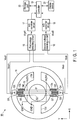
- a torque sensor 10 comprises, for example, a first structure 11, second structure 12, a plurality of third structures 13 serving as beam parts, first bridge circuit B1, and second bridge circuit B2.
- the first structure 11 and second structure 12 have, for example, annular shapes and, the second structure 12 and first structure 11 constitute concentric circles.
- a plurality of third structures 13a, 13b, 13c, and 13d couples the first structure 11 and second structure 12 to each other.
- the third structures 13a, 13b, 13c, and 13d function as, for example, strain-inducing parts.
- the first structure 11 is attached to, for example, one of joints of a robot arm (not shown), the one of joints being an object to be measured. More specifically, the first structure 11 is attached to, for example, a speed reducer (not shown) and, the speed reducer is coupled to a motor (not shown).
- the second structure 12 is attached to, for example, the other of the joints of the robot arm (not shown).
- the third structures 13a, 13b, 13c, and 13d transmit force (torque) between the first structure 11 and the second structure 12.
- the first structure 11, second structure 12, and third structures 13a, 13b, 13c, and 13d are constituted of, for example, a metal. However, if a mechanical strength sufficient for the torque to be applied can be obtained, it is also possible to form the first structure 11, second structure 12, and third structures 13a, 13b, 13c, and 13d of a material other than the metal.
- the third structures 13a and 13c which are arranged at positions 180° apart from each other are provided with the first bridge circuit B1 and second bridge circuit B2.
- the first bridge circuit B1 is constituted of first to fourth strain sensors (strain gages) G1 to G4, and second bridge circuit B2 is constituted of fifth to eighth strain sensors G5 to G8.
- the first strain sensor G1 and second strain sensor G2 of the first bridge circuit B1, and fifth strain sensor G5 and sixth strain sensor G6 of the second bridge circuit B2 are provided on the third structure 13a and, third strain sensor G3 and fourth strain sensor G4 of the first bridge circuit B1, and seventh strain sensor G7 and eighth strain sensor G8 of the second bridge circuit B2 are provided on the third structure 13c.
- Each of the first to eighth strain sensors G1 to G8 is constituted of, for example, a thin-film resistive element provided on, for example, a metallic plate (not shown) through an insulating film.
- the configuration of each of the first to eighth strain sensors G1 to G8 is not limited to this.
- the metallic plate of each of the first to eighth strain sensors G1 to G8 is fixed to the surface of the third structure 13a or third structure 13c by means of, for example, adhesive bonding, screwing, welding or the like.
- first strain sensor G1, second strain sensor G2, fifth strain sensor G5 and sixth strain sensor G6 are provided on the third structure 13a, and third strain sensor G3, fourth strain sensor G4, seventh strain sensor G7, and eighth strain sensor G8 are provided on the third structure 13c, the arrangement of the strain sensors is not limited to this.
- the metallic plate provided in each of the first to eighth strain sensors G1 to G8 may also be used as a strain body.
- the metallic plates of the first strain sensor G1, second strain sensor G2, fifth strain sensor G5, and sixth strain sensor G6 may be provided between the first structure 11 and second structure 12 at positions other than the third structures 13a, 13b, 13c, and 13d, and metallic plates of the third strain sensor G3, fourth strain sensor G4, seventh strain sensor G7, and eighth strain sensor G8 may be provided between the first structure 11 and second structure 12.
- the metallic plate of each strain sensor may be fixed to the first structure 11 or second structure 12 by means of, for example, adhesive bonding, screwing, welding or the like.
- first strain sensor G1 and third strain sensor G3 are connected in series, and second strain sensor G2 and fourth strain sensor G4 are also connected in series.
- the first strain sensor G1 and third strain sensor G3 connected in series are connected in parallel with the second strain sensor G2 and fourth strain sensor G4 connected in series
- a power-supply voltage Vo for example, 5 V is supplied to a connection node between the second strain sensor G2 and fourth strain sensor G4, and connection node between the first strain sensor G1 and third strain sensor G3 is grounded.
- the fifth strain sensor G5 and seventh strain sensor G7 are connected in series, and sixth strain sensor G6 and eighth strain sensor G8 are also connected in series.
- the fifth strain sensor G5 and seventh strain sensor G7 connected in series are connected in parallel with the sixth strain sensor G6 and eighth strain sensor G8 connected in series.
- a power-supply voltage Vo for example, 5 V is supplied to a connection node between the sixth strain sensor G6 and eighth strain sensor G8, and connection node between the fifth strain sensor G5 and seventh strain sensor G7 is grounded.
- connection node between the first strain sensor G1 and second strain sensor G2 is connected to a first input terminal of a first voltage detecting circuit 15, and connection node between the third strain sensor G3 and fourth strain sensor G4 is connected to a second input terminal of the first voltage detecting circuit 15.
- connection node between the fifth strain sensor G5 and sixth strain sensor G6 is connected to a first input terminal of a second voltage detecting circuit 16
- connection node between the seventh strain sensor G7 and eighth strain sensor G8 is connected to a second input terminal of the second voltage detecting circuit 16.
- the first voltage detecting circuit 15 detects an output voltage of the first bridge circuit B1
- second voltage detecting circuit 16 detects an output voltage of the second bridge circuit B2.
- Each of the first voltage detecting circuit 15 and second voltage detecting circuit 16 is constituted of, for example, voltage-dividing resistors and operational amplifier. However, the configuration of each of the first and second voltage detecting circuits 15 and 16 is not limited to this.
- the principle of operation of the first voltage detecting circuit 15 is as follows.
- the principle of operation of the second voltage detecting circuit 16 corresponding to the second bridge circuit B2 is identical to the first voltage detecting circuit 15.
- An output voltage Vout2 of the second voltage detecting circuit 16 is also obtained in the same manner as the first voltage detecting circuit 15.
- the output voltage Vout1 of the first voltage detecting circuit 15 is supplied to an analog-to-digital (A/D) converter circuit 17, and is converted into a digital signal and, output voltage Vout2 of the second voltage detecting circuit 16 is supplied to an A/D converter circuit 18, and is converted into a digital signal.
- Output signals of the A/D converter circuit 17 and A/D converter circuit 18 (hereinafter referred to also as output signals of the first bridge circuit B1 and second bridge circuit B2) are supplied to, for example, a controller 19 periodically.
- the controller 19 supplies one or both of the output signals of the A/D converter circuit 17 and A/D converter circuit 18 to an external device as an output signal or output signals of the torque sensor 10 or detects an abnormality of the torque sensor 10 to be described later.
- the controller 19 is provided with a storage part 20 capable of storing therein the output signals of the A/D converter circuit 17 and A/D converter circuit 18 for, for example, a fixed period.
- the output signals of the A/D converter circuit 17 and A/D converter circuit 18 stored in the storage part 20 are updated, for example, every fixed periods.
- a display device 21 is connected to the controller 19, for example.
- the display device 21 displays a detection output signal of the torque sensor 10 and signal or the like indicating that an abnormality of the torque sensor 10 has been detected.
- FIG. 2 and FIG. 3 are flowcharts for explaining the operation of the controller 19.
- both the first bridge circuit B1 and second bridge circuit B2 simultaneously operate, and the output voltages of the first bridge circuit B1 and second bridge circuit B2 are compared with each other. That is, the controller 19 obtains an absolute value of a difference between the output voltage Vout1 of the first bridge circuit B1 supplied thereto from the first voltage detecting circuit 15 through the A/D converter circuit 17 and output voltage Vout2 of the second bridge circuit B2 supplied thereto from the second voltage detecting circuit 16 through the A/D converter circuit 18, and compares the absolute value of the difference with a first threshold voltage (S1). It should be noted that the absolute value is not indispensable, and it is sufficient if the difference between both the output voltages can be obtained.
- the controller 19 determines whether or not a predetermined operation of the torque sensor 10 has been completed on the basis the output voltage of, for example, one of the first bridge circuit B1 and second bridge circuit B2 (S2).
- the predetermined operation implies, as described previously, an operation of, for example, supplying the output signal of the torque sensor 10 to the external device, detecting an abnormality of the torque sensor 10 or the like.
- FIG. 3 shows an example of the abnormality processing routine S3.
- the controller 19 obtains an absolute value of a difference between the output voltage Vout1 of the first bridge circuit B1 and last output voltage Vout11 of the first bridge circuit B1 stored in the storage part 20, and determines whether or not this absolute value is greater than a second threshold voltage (S31).
- the second threshold voltage may be equal to the first threshold voltage or may be less than or equal to the first threshold voltage.
- the controller 19 obtains an absolute value of a difference between the output voltage Vout2 of the second bridge circuit B2 and last output voltage Vout21 of the second bridge circuit B2 stored in the storage part 20, and determines whether or not this absolute value of the difference is greater than the second threshold voltage (S33).
- the abnormality processing routine is not limited to this and, when an abnormality is detected in S1, both the first bridge circuit B1 and second bridge circuit B2 may immediately be stopped, and it may be displayed on the display device 21 that an abnormality has occurred in the torque sensor 10.
- the torque sensor 10 is provided with the first bridge circuit B1 and second bridge circuit B2 and, when the difference (absolute value thereof) between the output voltage of the first bridge circuit B1 and output voltage of the second bridge circuit B2 is greater than the first threshold voltage, it is determined that an abnormality has occurred in one of the first bridge circuit B1 and second bridge circuit B2. Accordingly, it is possible to detect an abnormality of the torque sensor 10 before both the first bridge circuit B1 and second bridge circuit B2 go out of order. Therefore, the torque sensor 10 has a fail-safe function, and it is possible to prevent beforehand a robot arm equipped with the torque sensor 10 from causing a collision or the like.
- both the first bridge circuit B1 and second bridge circuit B2 are provided on the first structures 13a and 13c. That is, the first bridge circuit B1 and second bridge circuit B2 are arranged in parallel with each other.
- a first bridge circuit B1 and second bridge circuit B2 are arranged in such a manner that the first bridge circuit B1 and second bridge circuit B2 intersect each other.
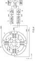
- FIG. 4 shows an example of the second embodiment.
- a first strain sensor G1 and second strain sensor G2 of the first bridge circuit B1 are arranged on a third structure 13a, and third strain sensor G3 and fourth strain sensor G4 of the first bridge circuit B1 are arranged on a third structure 13c.
- a fifth strain sensor G5 and sixth strain sensor G6 of the second bridge circuit B2 are arranged on a third structure 13b, and seventh strain sensor G7 and eighth strain sensor G8 of the second bridge circuit B2 are arranged on a third structure 13d.
- circuit configuration and operation are the same as the first embodiment.
- the first bridge circuit B1 and second bridge circuit B2 are arranged in such a manner that the first bridge circuit B1 and second bridge circuit B2 intersect each other, the first to fourth strain sensors G1 to G4 of the first bridge circuit B1 are arranged on the third structures 13a and 13c, and fifth to eighth strain sensors G5 to G8 of the second bridge circuit B2 are arranged on the third structures 13b and 13d other than the third structures 13a and 13c. Accordingly, it is possible to reduce the probability that both the first bridge circuit B1 and second bridge circuit B2 simultaneously go out of order.
- the abnormality of the first bridge circuit B1 or second bridge circuit B2 is detected on the basis of a digital signal.
- detection of the abnormality is not limited to this, and it is also possible to detect an abnormality of the first bridge circuit B1 or second bridge circuit B2 on the basis of an analog signal.
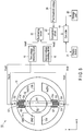
- FIG. 5 shows an example of a third embodiment.
- the first bridge circuit B1 and second bridge circuit B2 may be arranged in the same manner as the first embodiment, i.e., the first bridge circuit B1 and second bridge circuit B2 are arranged in parallel with each other, the first bridge circuit B1 and second bridge circuit B2 may be arranged in the same manner as the second embodiment, i.e., the first bridge circuit B1 and second bridge circuit B2 may be arranged in such a manner that the first bridge circuit B1 and second bridge circuit B2 intersect each other.
- Output voltages Vout+ and Vout- of the first bridge circuit B1 are supplied to a first voltage detecting circuit 15, and output voltages Vout+ and Vout- of the second bridge circuit B2 are supplied to a second voltage detecting circuit 16.
- An output voltage Vout1 of the first voltage detecting circuit 15 and output voltage Vout2 of the second voltage detecting circuit 16 are supplied to a subtracting circuit 22.
- the subtracting circuit 22 outputs a voltage of a difference between the output voltage Vout1 of the first voltage detecting circuit 15 and output voltage Vout2 of the second voltage detecting circuit 16.
- An output voltage of the subtracting circuit 22 and first threshold voltage 24 are supplied to a comparison circuit 23.
- the comparison circuit 23 compares the output voltage of the subtracting circuit 22 and first threshold voltage 24 with each other.
- a comparison result of the comparison circuit 23 is supplied to a controller 19.
- the controller 19 stops power supply to, for example, the first bridge circuit B1 and second bridge circuit B2, and stops, for example, the operation of the robot arm.
- the controller 19 may also be configured to detect one of the first bridge circuit B1 and second bridge circuit B2, the one being the bridge circuit having an abnormality.
- the present invention is not limited to the above embodiments as it is, and at the implementation stage, the constituent elements can be modified and embodied without departing from the scope of the invention.
- various inventions can be formed by appropriate combinations of a plurality of constituent elements disclosed in the above embodiments. For example, some components may be deleted from all the components shown in the embodiment. Furthermore, components in different embodiments may be combined as appropriate.
- the present invention can be applied to, for example, a torque sensor provided at a joint of a robot arm.
- 10 torque sensor, 11 ... first structure, 12 ... second structure, 13a, 13b, 13c, 13d ... third structure, B1 ... first bridge circuit, B2 ... second bridge circuit, G1 to G8 ... first strain sensor to eighth strain sensor, 15 ... first voltage detecting circuit, 16 ... second voltage detecting circuit, 19 ... controller, 20 ... storage part, 21 ... display device.
Landscapes
- Physics & Mathematics (AREA)
- General Physics & Mathematics (AREA)
- Engineering & Computer Science (AREA)
- Chemical & Material Sciences (AREA)
- Analytical Chemistry (AREA)
- Human Computer Interaction (AREA)
- Robotics (AREA)
- Mechanical Engineering (AREA)
- Force Measurement Appropriate To Specific Purposes (AREA)
- Measurement Of Length, Angles, Or The Like Using Electric Or Magnetic Means (AREA)
- Transmission And Conversion Of Sensor Element Output (AREA)
Applications Claiming Priority (2)
| Application Number | Priority Date | Filing Date | Title |
|---|---|---|---|
| JP2017023885A JP6692762B2 (ja) | 2017-02-13 | 2017-02-13 | トルクセンサ |
| PCT/JP2017/042906 WO2018146917A1 (ja) | 2017-02-13 | 2017-11-29 | トルクセンサ |
Publications (3)
| Publication Number | Publication Date |
|---|---|
| EP3581908A1 true EP3581908A1 (de) | 2019-12-18 |
| EP3581908A4 EP3581908A4 (de) | 2020-12-30 |
| EP3581908B1 EP3581908B1 (de) | 2023-06-28 |
Family
ID=63108002
Family Applications (1)
| Application Number | Title | Priority Date | Filing Date |
|---|---|---|---|
| EP17895539.9A Active EP3581908B1 (de) | 2017-02-13 | 2017-11-29 | Drehmomentsensor |
Country Status (5)
| Country | Link |
|---|---|
| US (1) | US10955309B2 (de) |
| EP (1) | EP3581908B1 (de) |
| JP (1) | JP6692762B2 (de) |
| CN (1) | CN110121638A (de) |
| WO (1) | WO2018146917A1 (de) |
Families Citing this family (10)
| Publication number | Priority date | Publication date | Assignee | Title |
|---|---|---|---|---|
| JP6976892B2 (ja) * | 2018-03-29 | 2021-12-08 | 日本電産コパル電子株式会社 | トルクセンサ |
| JP2020012660A (ja) * | 2018-07-13 | 2020-01-23 | 日本電産コパル電子株式会社 | トルクセンサ |
| JP6964212B2 (ja) * | 2019-07-24 | 2021-11-10 | Semitec株式会社 | 接触力センサ及び接触力センサを備えた装置 |
| DE102020101424B3 (de) * | 2020-01-22 | 2021-04-15 | Schaeffler Technologies AG & Co. KG | Verfahren zur Überprüfung einer Anordnung von mindestens drei Dehnungsmessstreifen sowie Spannungswellengetriebe |
| EP3896416B1 (de) * | 2020-04-16 | 2025-08-13 | TE Connectivity Sensors France | Drehmomentmessvorrichtung |
| CN111347446A (zh) * | 2020-04-17 | 2020-06-30 | 成都卡诺普自动化控制技术有限公司 | 一种中空型协作机器人机械臂关节 |
| CN111579133B (zh) * | 2020-05-27 | 2021-10-01 | 安徽大学 | 一种力分辨率连续可调的变构型力传感器 |
| CN112665765A (zh) * | 2020-12-01 | 2021-04-16 | 哈尔滨工业大学 | 一种基于并联分载原理的机器人高刚度关节力矩传感器 |
| TWI805978B (zh) * | 2020-12-22 | 2023-06-21 | 達明機器人股份有限公司 | 雙迴路力矩感知系統及其感知方法 |
| CN115790926B (zh) * | 2022-12-01 | 2023-07-04 | 华中科技大学 | 一种电动机组的转矩测量方法及装置 |
Family Cites Families (20)
| Publication number | Priority date | Publication date | Assignee | Title |
|---|---|---|---|---|
| JPS5640905B2 (de) | 1973-10-31 | 1981-09-24 | ||
| US3915015A (en) * | 1974-03-18 | 1975-10-28 | Stanford Research Inst | Strain gauge transducer system |
| JPS5947494B2 (ja) | 1977-01-28 | 1984-11-19 | 株式会社日立製作所 | 弾性表面波フイルタ |
| JP3444952B2 (ja) * | 1994-02-28 | 2003-09-08 | 大和製衡株式会社 | ロードセルの故障検出装置及び故障復帰装置 |
| JP4026247B2 (ja) * | 1998-10-01 | 2007-12-26 | 日本精工株式会社 | トルクセンサ |
| US20080204266A1 (en) * | 2004-02-03 | 2008-08-28 | Jussi Malmberg | Method and Device For Implementing Vibration Output Commands in Mobile Terminal Devices |
| JP4764619B2 (ja) * | 2004-08-23 | 2011-09-07 | 株式会社エー・アンド・デイ | 回転型分力計測装置 |
| CN101365609A (zh) * | 2005-12-13 | 2009-02-11 | Tk电子控股公司 | 信号处理系统和方法 |
| JP2007255953A (ja) * | 2006-03-22 | 2007-10-04 | Hitachi Ltd | 力学量測定装置 |
| KR101151125B1 (ko) * | 2007-08-27 | 2012-06-01 | 가부시키가이샤 히타치세이사쿠쇼 | 반도체 왜곡 센서 |
| DE102009053043A1 (de) * | 2009-11-16 | 2011-05-19 | Baumer Innotec Ag | Kraftmesszelle zur Messung der Einspritzkraft beim Spritzgießen |
| EP2510325A2 (de) * | 2009-12-08 | 2012-10-17 | Abb Ag | Mehrachsige kraft-drehmoment-sensoren |
| JP5640905B2 (ja) * | 2011-06-14 | 2014-12-17 | トヨタ自動車株式会社 | 起歪体及びこれを含む装置 |
| JP5947494B2 (ja) * | 2011-06-30 | 2016-07-06 | トヨタ自動車株式会社 | トルク計測装置の製造方法 |
| US8966996B2 (en) * | 2011-07-27 | 2015-03-03 | Tri-Force Management Corporation | Force sensor |
| JP5699904B2 (ja) * | 2011-10-28 | 2015-04-15 | トヨタ自動車株式会社 | 起歪体及びトルクセンサ |
| CN203164326U (zh) * | 2013-03-11 | 2013-08-28 | 唐山钢铁集团微尔自动化有限公司 | 一种电阻应变传感器的数显式检测装置 |
| JP6135408B2 (ja) * | 2013-09-04 | 2017-05-31 | トヨタ自動車株式会社 | トルクセンサ、駆動装置、及びロボット |
| US10422707B2 (en) * | 2016-01-19 | 2019-09-24 | Ati Industrial Automation, Inc. | Compact robotic force/torque sensor including strain gages |
| JP6214072B1 (ja) * | 2016-08-09 | 2017-10-18 | 株式会社トライフォース・マネジメント | 力覚センサ |
-
2017
- 2017-02-13 JP JP2017023885A patent/JP6692762B2/ja active Active
- 2017-11-29 EP EP17895539.9A patent/EP3581908B1/de active Active
- 2017-11-29 CN CN201780080958.8A patent/CN110121638A/zh active Pending
- 2017-11-29 WO PCT/JP2017/042906 patent/WO2018146917A1/ja not_active Ceased
-
2019
- 2019-06-25 US US16/451,839 patent/US10955309B2/en not_active Expired - Fee Related
Also Published As
| Publication number | Publication date |
|---|---|
| JP2018132313A (ja) | 2018-08-23 |
| US10955309B2 (en) | 2021-03-23 |
| EP3581908B1 (de) | 2023-06-28 |
| EP3581908A4 (de) | 2020-12-30 |
| CN110121638A (zh) | 2019-08-13 |
| US20190346329A1 (en) | 2019-11-14 |
| WO2018146917A1 (ja) | 2018-08-16 |
| JP6692762B2 (ja) | 2020-05-13 |
Similar Documents
| Publication | Publication Date | Title |
|---|---|---|
| EP3581908B1 (de) | Drehmomentsensor | |
| JP5333619B2 (ja) | 電圧検出装置および結合回路 | |
| JP4908608B2 (ja) | 電気負荷の電流制御装置 | |
| JP6515989B2 (ja) | 電動パワーステアリング装置 | |
| EP3232209B1 (de) | Isolationswiderstandmessvorrichtung und -verfahren | |
| JP6512268B2 (ja) | 車両用舵角検出装置及びそれを搭載した電動パワーステアリング装置 | |
| US20210199539A1 (en) | Test device | |
| US8427352B2 (en) | A/D converter circuit including pulse circulation circuit with delay units coupled together in ring shape | |
| CN111070237B (zh) | 一体化关节及一体化关节多传感器控制系统和方法 | |
| EP3779389A1 (de) | Drehmomentsensor | |
| EP3779388A1 (de) | Drehmomentsensor | |
| WO2018207319A1 (ja) | 電子制御装置 | |
| JP2017083303A (ja) | 半導体装置およびセル電圧の測定方法 | |
| JP4916543B2 (ja) | 電気負荷の電流制御装置 | |
| CN104132015B (zh) | 一种轧机液压伺服阀零漂补偿方法及装置 | |
| US20180264645A1 (en) | Device and method for controlling motor | |
| US20180017455A1 (en) | Sensor device | |
| JP5846092B2 (ja) | 電圧検出装置 | |
| EP3130894B1 (de) | Anomalieerkennungsvorrichtung für sensoren und sensorvorrichtung | |
| KR102612239B1 (ko) | 모터 제어 장치 및 방법 | |
| JP2010117246A (ja) | 電圧測定装置 | |
| JP6315273B2 (ja) | 絶縁状態測定装置 | |
| US8939024B2 (en) | Angular velocity sensor | |
| JP5016538B2 (ja) | A/d変換装置及び方法 | |
| JP4064303B2 (ja) | センスコンパレータ回路とそのオフセット補償方法 |
Legal Events
| Date | Code | Title | Description |
|---|---|---|---|
| STAA | Information on the status of an ep patent application or granted ep patent |
Free format text: STATUS: THE INTERNATIONAL PUBLICATION HAS BEEN MADE |
|
| PUAI | Public reference made under article 153(3) epc to a published international application that has entered the european phase |
Free format text: ORIGINAL CODE: 0009012 |
|
| STAA | Information on the status of an ep patent application or granted ep patent |
Free format text: STATUS: REQUEST FOR EXAMINATION WAS MADE |
|
| 17P | Request for examination filed |
Effective date: 20190625 |
|
| AK | Designated contracting states |
Kind code of ref document: A1 Designated state(s): AL AT BE BG CH CY CZ DE DK EE ES FI FR GB GR HR HU IE IS IT LI LT LU LV MC MK MT NL NO PL PT RO RS SE SI SK SM TR |
|
| AX | Request for extension of the european patent |
Extension state: BA ME |
|
| DAV | Request for validation of the european patent (deleted) | ||
| DAX | Request for extension of the european patent (deleted) | ||
| A4 | Supplementary search report drawn up and despatched |
Effective date: 20201126 |
|
| RIC1 | Information provided on ipc code assigned before grant |
Ipc: G01L 3/10 20060101ALI20201120BHEP Ipc: G01L 25/00 20060101AFI20201120BHEP Ipc: G01L 5/00 20060101ALI20201120BHEP |
|
| STAA | Information on the status of an ep patent application or granted ep patent |
Free format text: STATUS: EXAMINATION IS IN PROGRESS |
|
| 17Q | First examination report despatched |
Effective date: 20220715 |
|
| GRAP | Despatch of communication of intention to grant a patent |
Free format text: ORIGINAL CODE: EPIDOSNIGR1 |
|
| STAA | Information on the status of an ep patent application or granted ep patent |
Free format text: STATUS: GRANT OF PATENT IS INTENDED |
|
| INTG | Intention to grant announced |
Effective date: 20230120 |
|
| GRAS | Grant fee paid |
Free format text: ORIGINAL CODE: EPIDOSNIGR3 |
|
| GRAA | (expected) grant |
Free format text: ORIGINAL CODE: 0009210 |
|
| STAA | Information on the status of an ep patent application or granted ep patent |
Free format text: STATUS: THE PATENT HAS BEEN GRANTED |
|
| AK | Designated contracting states |
Kind code of ref document: B1 Designated state(s): AL AT BE BG CH CY CZ DE DK EE ES FI FR GB GR HR HU IE IS IT LI LT LU LV MC MK MT NL NO PL PT RO RS SE SI SK SM TR |
|
| REG | Reference to a national code |
Ref country code: CH Ref legal event code: EP |
|
| REG | Reference to a national code |
Ref country code: AT Ref legal event code: REF Ref document number: 1583101 Country of ref document: AT Kind code of ref document: T Effective date: 20230715 |
|
| REG | Reference to a national code |
Ref country code: IE Ref legal event code: FG4D |
|
| REG | Reference to a national code |
Ref country code: DE Ref legal event code: R096 Ref document number: 602017070820 Country of ref document: DE |
|
| REG | Reference to a national code |
Ref country code: LT Ref legal event code: MG9D |
|
| PG25 | Lapsed in a contracting state [announced via postgrant information from national office to epo] |
Ref country code: SE Free format text: LAPSE BECAUSE OF FAILURE TO SUBMIT A TRANSLATION OF THE DESCRIPTION OR TO PAY THE FEE WITHIN THE PRESCRIBED TIME-LIMIT Effective date: 20230628 Ref country code: NO Free format text: LAPSE BECAUSE OF FAILURE TO SUBMIT A TRANSLATION OF THE DESCRIPTION OR TO PAY THE FEE WITHIN THE PRESCRIBED TIME-LIMIT Effective date: 20230928 |
|
| REG | Reference to a national code |
Ref country code: NL Ref legal event code: MP Effective date: 20230628 |
|
| REG | Reference to a national code |
Ref country code: AT Ref legal event code: MK05 Ref document number: 1583101 Country of ref document: AT Kind code of ref document: T Effective date: 20230628 |
|
| PG25 | Lapsed in a contracting state [announced via postgrant information from national office to epo] |
Ref country code: RS Free format text: LAPSE BECAUSE OF FAILURE TO SUBMIT A TRANSLATION OF THE DESCRIPTION OR TO PAY THE FEE WITHIN THE PRESCRIBED TIME-LIMIT Effective date: 20230628 Ref country code: NL Free format text: LAPSE BECAUSE OF FAILURE TO SUBMIT A TRANSLATION OF THE DESCRIPTION OR TO PAY THE FEE WITHIN THE PRESCRIBED TIME-LIMIT Effective date: 20230628 Ref country code: LV Free format text: LAPSE BECAUSE OF FAILURE TO SUBMIT A TRANSLATION OF THE DESCRIPTION OR TO PAY THE FEE WITHIN THE PRESCRIBED TIME-LIMIT Effective date: 20230628 Ref country code: LT Free format text: LAPSE BECAUSE OF FAILURE TO SUBMIT A TRANSLATION OF THE DESCRIPTION OR TO PAY THE FEE WITHIN THE PRESCRIBED TIME-LIMIT Effective date: 20230628 Ref country code: HR Free format text: LAPSE BECAUSE OF FAILURE TO SUBMIT A TRANSLATION OF THE DESCRIPTION OR TO PAY THE FEE WITHIN THE PRESCRIBED TIME-LIMIT Effective date: 20230628 Ref country code: GR Free format text: LAPSE BECAUSE OF FAILURE TO SUBMIT A TRANSLATION OF THE DESCRIPTION OR TO PAY THE FEE WITHIN THE PRESCRIBED TIME-LIMIT Effective date: 20230929 |
|
| PG25 | Lapsed in a contracting state [announced via postgrant information from national office to epo] |
Ref country code: FI Free format text: LAPSE BECAUSE OF FAILURE TO SUBMIT A TRANSLATION OF THE DESCRIPTION OR TO PAY THE FEE WITHIN THE PRESCRIBED TIME-LIMIT Effective date: 20230628 |
|
| PG25 | Lapsed in a contracting state [announced via postgrant information from national office to epo] |
Ref country code: SK Free format text: LAPSE BECAUSE OF FAILURE TO SUBMIT A TRANSLATION OF THE DESCRIPTION OR TO PAY THE FEE WITHIN THE PRESCRIBED TIME-LIMIT Effective date: 20230628 |
|
| PG25 | Lapsed in a contracting state [announced via postgrant information from national office to epo] |
Ref country code: ES Free format text: LAPSE BECAUSE OF FAILURE TO SUBMIT A TRANSLATION OF THE DESCRIPTION OR TO PAY THE FEE WITHIN THE PRESCRIBED TIME-LIMIT Effective date: 20230628 |
|
| PG25 | Lapsed in a contracting state [announced via postgrant information from national office to epo] |
Ref country code: IS Free format text: LAPSE BECAUSE OF FAILURE TO SUBMIT A TRANSLATION OF THE DESCRIPTION OR TO PAY THE FEE WITHIN THE PRESCRIBED TIME-LIMIT Effective date: 20231028 |
|
| PG25 | Lapsed in a contracting state [announced via postgrant information from national office to epo] |
Ref country code: SM Free format text: LAPSE BECAUSE OF FAILURE TO SUBMIT A TRANSLATION OF THE DESCRIPTION OR TO PAY THE FEE WITHIN THE PRESCRIBED TIME-LIMIT Effective date: 20230628 Ref country code: SK Free format text: LAPSE BECAUSE OF FAILURE TO SUBMIT A TRANSLATION OF THE DESCRIPTION OR TO PAY THE FEE WITHIN THE PRESCRIBED TIME-LIMIT Effective date: 20230628 Ref country code: RO Free format text: LAPSE BECAUSE OF FAILURE TO SUBMIT A TRANSLATION OF THE DESCRIPTION OR TO PAY THE FEE WITHIN THE PRESCRIBED TIME-LIMIT Effective date: 20230628 Ref country code: PT Free format text: LAPSE BECAUSE OF FAILURE TO SUBMIT A TRANSLATION OF THE DESCRIPTION OR TO PAY THE FEE WITHIN THE PRESCRIBED TIME-LIMIT Effective date: 20231030 Ref country code: IS Free format text: LAPSE BECAUSE OF FAILURE TO SUBMIT A TRANSLATION OF THE DESCRIPTION OR TO PAY THE FEE WITHIN THE PRESCRIBED TIME-LIMIT Effective date: 20231028 Ref country code: ES Free format text: LAPSE BECAUSE OF FAILURE TO SUBMIT A TRANSLATION OF THE DESCRIPTION OR TO PAY THE FEE WITHIN THE PRESCRIBED TIME-LIMIT Effective date: 20230628 Ref country code: EE Free format text: LAPSE BECAUSE OF FAILURE TO SUBMIT A TRANSLATION OF THE DESCRIPTION OR TO PAY THE FEE WITHIN THE PRESCRIBED TIME-LIMIT Effective date: 20230628 Ref country code: CZ Free format text: LAPSE BECAUSE OF FAILURE TO SUBMIT A TRANSLATION OF THE DESCRIPTION OR TO PAY THE FEE WITHIN THE PRESCRIBED TIME-LIMIT Effective date: 20230628 Ref country code: AT Free format text: LAPSE BECAUSE OF FAILURE TO SUBMIT A TRANSLATION OF THE DESCRIPTION OR TO PAY THE FEE WITHIN THE PRESCRIBED TIME-LIMIT Effective date: 20230628 |
|
| PG25 | Lapsed in a contracting state [announced via postgrant information from national office to epo] |
Ref country code: PL Free format text: LAPSE BECAUSE OF FAILURE TO SUBMIT A TRANSLATION OF THE DESCRIPTION OR TO PAY THE FEE WITHIN THE PRESCRIBED TIME-LIMIT Effective date: 20230628 |
|
| REG | Reference to a national code |
Ref country code: DE Ref legal event code: R097 Ref document number: 602017070820 Country of ref document: DE |
|
| PG25 | Lapsed in a contracting state [announced via postgrant information from national office to epo] |
Ref country code: DK Free format text: LAPSE BECAUSE OF FAILURE TO SUBMIT A TRANSLATION OF THE DESCRIPTION OR TO PAY THE FEE WITHIN THE PRESCRIBED TIME-LIMIT Effective date: 20230628 |
|
| PLBE | No opposition filed within time limit |
Free format text: ORIGINAL CODE: 0009261 |
|
| STAA | Information on the status of an ep patent application or granted ep patent |
Free format text: STATUS: NO OPPOSITION FILED WITHIN TIME LIMIT |
|
| PG25 | Lapsed in a contracting state [announced via postgrant information from national office to epo] |
Ref country code: IT Free format text: LAPSE BECAUSE OF FAILURE TO SUBMIT A TRANSLATION OF THE DESCRIPTION OR TO PAY THE FEE WITHIN THE PRESCRIBED TIME-LIMIT Effective date: 20230628 |
|
| 26N | No opposition filed |
Effective date: 20240402 |
|
| REG | Reference to a national code |
Ref country code: CH Ref legal event code: PL |
|
| PG25 | Lapsed in a contracting state [announced via postgrant information from national office to epo] |
Ref country code: MC Free format text: LAPSE BECAUSE OF FAILURE TO SUBMIT A TRANSLATION OF THE DESCRIPTION OR TO PAY THE FEE WITHIN THE PRESCRIBED TIME-LIMIT Effective date: 20230628 |
|
| PG25 | Lapsed in a contracting state [announced via postgrant information from national office to epo] |
Ref country code: LU Free format text: LAPSE BECAUSE OF NON-PAYMENT OF DUE FEES Effective date: 20231129 |
|
| PG25 | Lapsed in a contracting state [announced via postgrant information from national office to epo] |
Ref country code: CH Free format text: LAPSE BECAUSE OF NON-PAYMENT OF DUE FEES Effective date: 20231130 |
|
| GBPC | Gb: european patent ceased through non-payment of renewal fee |
Effective date: 20231129 |
|
| PG25 | Lapsed in a contracting state [announced via postgrant information from national office to epo] |
Ref country code: MC Free format text: LAPSE BECAUSE OF FAILURE TO SUBMIT A TRANSLATION OF THE DESCRIPTION OR TO PAY THE FEE WITHIN THE PRESCRIBED TIME-LIMIT Effective date: 20230628 Ref country code: LU Free format text: LAPSE BECAUSE OF NON-PAYMENT OF DUE FEES Effective date: 20231129 Ref country code: CH Free format text: LAPSE BECAUSE OF NON-PAYMENT OF DUE FEES Effective date: 20231130 Ref country code: SI Free format text: LAPSE BECAUSE OF FAILURE TO SUBMIT A TRANSLATION OF THE DESCRIPTION OR TO PAY THE FEE WITHIN THE PRESCRIBED TIME-LIMIT Effective date: 20230628 |
|
| REG | Reference to a national code |
Ref country code: BE Ref legal event code: MM Effective date: 20231130 |
|
| REG | Reference to a national code |
Ref country code: IE Ref legal event code: MM4A |
|
| PG25 | Lapsed in a contracting state [announced via postgrant information from national office to epo] |
Ref country code: IE Free format text: LAPSE BECAUSE OF NON-PAYMENT OF DUE FEES Effective date: 20231129 |
|
| PG25 | Lapsed in a contracting state [announced via postgrant information from national office to epo] |
Ref country code: GB Free format text: LAPSE BECAUSE OF NON-PAYMENT OF DUE FEES Effective date: 20231129 |
|
| PG25 | Lapsed in a contracting state [announced via postgrant information from national office to epo] |
Ref country code: BE Free format text: LAPSE BECAUSE OF NON-PAYMENT OF DUE FEES Effective date: 20231130 |
|
| PG25 | Lapsed in a contracting state [announced via postgrant information from national office to epo] |
Ref country code: FR Free format text: LAPSE BECAUSE OF NON-PAYMENT OF DUE FEES Effective date: 20231130 |
|
| PG25 | Lapsed in a contracting state [announced via postgrant information from national office to epo] |
Ref country code: IE Free format text: LAPSE BECAUSE OF NON-PAYMENT OF DUE FEES Effective date: 20231129 Ref country code: GB Free format text: LAPSE BECAUSE OF NON-PAYMENT OF DUE FEES Effective date: 20231129 Ref country code: FR Free format text: LAPSE BECAUSE OF NON-PAYMENT OF DUE FEES Effective date: 20231130 Ref country code: BE Free format text: LAPSE BECAUSE OF NON-PAYMENT OF DUE FEES Effective date: 20231130 |
|
| PG25 | Lapsed in a contracting state [announced via postgrant information from national office to epo] |
Ref country code: BG Free format text: LAPSE BECAUSE OF FAILURE TO SUBMIT A TRANSLATION OF THE DESCRIPTION OR TO PAY THE FEE WITHIN THE PRESCRIBED TIME-LIMIT Effective date: 20230628 |
|
| PG25 | Lapsed in a contracting state [announced via postgrant information from national office to epo] |
Ref country code: BG Free format text: LAPSE BECAUSE OF FAILURE TO SUBMIT A TRANSLATION OF THE DESCRIPTION OR TO PAY THE FEE WITHIN THE PRESCRIBED TIME-LIMIT Effective date: 20230628 |
|
| PG25 | Lapsed in a contracting state [announced via postgrant information from national office to epo] |
Ref country code: CY Free format text: LAPSE BECAUSE OF FAILURE TO SUBMIT A TRANSLATION OF THE DESCRIPTION OR TO PAY THE FEE WITHIN THE PRESCRIBED TIME-LIMIT; INVALID AB INITIO Effective date: 20171129 |
|
| PG25 | Lapsed in a contracting state [announced via postgrant information from national office to epo] |
Ref country code: HU Free format text: LAPSE BECAUSE OF FAILURE TO SUBMIT A TRANSLATION OF THE DESCRIPTION OR TO PAY THE FEE WITHIN THE PRESCRIBED TIME-LIMIT; INVALID AB INITIO Effective date: 20171129 |
|
| PG25 | Lapsed in a contracting state [announced via postgrant information from national office to epo] |
Ref country code: TR Free format text: LAPSE BECAUSE OF FAILURE TO SUBMIT A TRANSLATION OF THE DESCRIPTION OR TO PAY THE FEE WITHIN THE PRESCRIBED TIME-LIMIT Effective date: 20230628 |
|
| PGFP | Annual fee paid to national office [announced via postgrant information from national office to epo] |
Ref country code: DE Payment date: 20250930 Year of fee payment: 9 |