EP3553578A1 - Glasfaserbandkern mit sporadischer verbindung, verfahren zur herstellung davon, glasfaserkabel und glasfasercord - Google Patents
Glasfaserbandkern mit sporadischer verbindung, verfahren zur herstellung davon, glasfaserkabel und glasfasercord Download PDFInfo
- Publication number
- EP3553578A1 EP3553578A1 EP17877839.5A EP17877839A EP3553578A1 EP 3553578 A1 EP3553578 A1 EP 3553578A1 EP 17877839 A EP17877839 A EP 17877839A EP 3553578 A1 EP3553578 A1 EP 3553578A1
- Authority
- EP
- European Patent Office
- Prior art keywords
- optical fiber
- intermittently
- ribbon
- optical fibers
- coupled type
- Prior art date
- Legal status (The legal status is an assumption and is not a legal conclusion. Google has not performed a legal analysis and makes no representation as to the accuracy of the status listed.)
- Granted
Links
Images




Classifications
-
- G—PHYSICS
- G02—OPTICS
- G02B—OPTICAL ELEMENTS, SYSTEMS OR APPARATUS
- G02B6/00—Light guides; Structural details of arrangements comprising light guides and other optical elements, e.g. couplings
- G02B6/44—Mechanical structures for providing tensile strength and external protection for fibres, e.g. optical transmission cables
- G02B6/4479—Manufacturing methods of optical cables
- G02B6/448—Ribbon cables
-
- G—PHYSICS
- G02—OPTICS
- G02B—OPTICAL ELEMENTS, SYSTEMS OR APPARATUS
- G02B6/00—Light guides; Structural details of arrangements comprising light guides and other optical elements, e.g. couplings
- G02B6/24—Coupling light guides
- G02B6/26—Optical coupling means
- G02B6/262—Optical details of coupling light into, or out of, or between fibre ends, e.g. special fibre end shapes or associated optical elements
-
- G—PHYSICS
- G02—OPTICS
- G02B—OPTICAL ELEMENTS, SYSTEMS OR APPARATUS
- G02B6/00—Light guides; Structural details of arrangements comprising light guides and other optical elements, e.g. couplings
- G02B6/44—Mechanical structures for providing tensile strength and external protection for fibres, e.g. optical transmission cables
- G02B6/4401—Optical cables
- G02B6/4407—Optical cables with internal fluted support member
- G02B6/4409—Optical cables with internal fluted support member for ribbons
Definitions
- the present invention relates to an intermittently-coupled type optical fiber ribbon, an optical fiber cable, an optical fiber cord, and a manufacturing method of the intermittently-coupled type optical fiber ribbon.
- the application is based upon and claims the benefit of priority from the prior Japanese Patent Application No. 2016-236568 filed on December 6, 2016 , the entire contents of which are incorporated herein by reference.
- An intermittently-coupled type optical fiber ribbon which a coupling part in which adjacent optical fibers are connected by an adhesive resin and a non-coupling part in which adjacent optical fibers are not connected by an adhesive resin are intermittently provided in a longitudinal direction in a state where a plurality of optical fibers are arranged in parallel (for example, see Patent Documents 1 to 3).
- An aspect of the present disclosure is an intermittently-coupled type optical fiber ribbon in which a plurality of ribbon type paired optical fibers each of which is integrally formed by bringing two optical fibers into contact with each other are arranged in parallel, and a coupling part in which adjacent ribbon type paired optical fibers are connected to each other and a non-coupling part in which ribbon type paired optical fibers are not connected are intermittently provided in a longitudinal direction, wherein an outer diameter dimension of the optical fiber is 0.22 mm or less, and a center distance of optical fibers adjacent with the coupling part interposed therebetween between the adjacent ribbon type paired optical fibers is 0.28 ⁇ 0.03 mm.
- An aspect of the present disclosure is an optical fiber cable comprising:
- An aspect of the present disclosure is an optical fiber cable comprising:
- An aspect of the present disclosure is an optical fiber cord comprising:
- An aspect of the present disclosure is a manufacturing method of an intermittently-coupled type optical fiber ribbon, the method comprising:
- an examination on the outer diameter of an optical fiber used in the intermittently-coupled type optical fiber ribbon is made from 0.25 mm (typical diameter, 250 ⁇ m) to 0.22 mm (220 ⁇ m), for example.
- a general optical fiber ribbon uses an optical fiber having a diameter of 0.25 mm.
- the pitch of the V groove is set to 0.25 mm.
- the cross-sectional area of the intermittently-coupled type optical fiber ribbon is almost the same as that of the typical intermittently-coupled type optical fiber ribbon in which the outer diameter of the optical fiber is 0.25 mm. For this reason, although the outer diameter of the optical fiber is small, it is not possible to increase the density of the optical fiber cable or the optical fiber cord using the intermittently-coupled type optical fiber ribbon.
- On object of the present disclosure is to provide an intermittently-coupled type optical fiber ribbon, an optical fiber cable and optical fiber cord using the intermittently-coupled type optical fiber ribbon, and a manufacturing method of the intermittently-coupled type optical fiber ribbon in which a fusion machine in which a pitch of a V groove is set to 0.25 mm can be used to fuse without any problems, and a density of the optical fiber cable and the optical fiber cord can be increased.
- the fusion machine in which the pitch of the V groove is set to 0.25 mm can be used to fuse without any problems, and the density of the optical fiber cable and the optical fiber cord can be increased.
- An intermittently-coupled type optical fiber ribbon according to one aspect is
- An optical fiber cable includes: (6) a cylindrical tube; and a plurality of intermittently-coupled type optical fiber ribbons according to any one of the above (1) to (5), in which the plurality of intermittently-coupled type optical fiber ribbons are covered with the tube.
- a plurality of intermittently-coupled type optical fiber ribbons according to any one of (1) to (5) are achieved.
- the density can be increased compared to the conventional optical fiber cable.
- the outer diameter can be made smaller than that of the conventional optical fiber cable.
- An optical fiber cable includes: (7) a slot rod having a plurality of slot grooves; and the plurality of intermittently-coupled type optical fiber ribbons according to any one of the above (1) to (5), in which the plurality of intermittently-coupled type optical fiber ribbons are housed in each of the slot grooves.
- a plurality of intermittently-coupled type optical fiber ribbons according to any one of (1) to (5) are achieved.
- the density can be increased compared to the conventional optical fiber cable.
- the outer diameter can be made smaller than that of the conventional optical fiber cable.
- An optical fiber cord includes: (8) a jacket; and the intermittently-coupled type optical fiber ribbon according to any one of the above (1) to (5), in which the intermittently-coupled type optical fiber ribbon is covered with the jacket.
- the outer diameter of the optical fiber cord can be reduced compared to the conventional one.
- the density of the optical fiber cord can be increased compared to the conventional one.
- a manufacturing method of an intermittently-coupled type optical fiber ribbon includes: (9) a process of arranging a plurality of optical fibers having an outer diameter dimension of 0.22 mm or less in parallel and integrating every two optical fibers by bringing the optical fibers into contact with each other, thereby forming a plurality of ribbon type paired optical fibers; an applying process of intermittently applying a coupling resin between the adjacent ribbon type paired optical fibers in the plurality of ribbon type paired optical fibers in a longitudinal direction; and a curing process of curing the coupling resin, in which when the applying process and the curing process are performed, a coupling part in which the adjacent ribbon type paired optical fibers are connected with each other and a non-coupling part in which the ribbon type paired optical fibers are not connected are intermittently provided in a longitudinal direction, and a center distance of optical fibers adjacent with the coupling part interposed therebetween between the ribbon type paired optical fibers is set to 0.28 ⁇ 0.03 mm.
- the optical fibers are arranged at the positions corresponding to the V grooves, respectively.
- the optical fibers can be placed one by one on each of the V grooves, and the fusion machine in which the pitch of the V groove is set to 0.25 mm can be used to fuse without any problems.
- the dual-core optical fiber ribbon is used which is integrally formed by bringing two optical fibers having the outer diameter dimension of 0.22 mm or less into contact with each other.
- the width of the entire intermittently-coupled type optical fiber ribbon in the parallel direction is narrower than that of the conventional intermittently-coupled type optical fiber ribbon, and the sectional area of the intermittently-coupled type optical fiber ribbon can be reduced. Therefore, when the intermittently-coupled type optical fiber ribbon is used for the optical fiber cable or the optical fiber cord, the density of the optical fiber cable or the optical fiber cord can be increased.
- an intermittently-coupled type optical fiber ribbon 1 a plurality of (six in the example of Figs. 1 and 2 ) ribbon type paired optical fibers 12A to 12F which are integrally formed by bringing two optical fibers into contact with each other are arranged in parallel.
- a coupling part 13 in which adjacent ribbon type paired optical fibers are connected to each other and a non-coupling part 14 in which adjacent ribbon type paired optical fibers are not connected to each other are intermittently provided in the longitudinal direction.
- the plan view of Fig. 1 illustrates a state where the non-coupling part 14 is opened in the parallel direction
- FIG. 2 illustrates a cross section taken along line A-A of Fig. 1 in a state where the non-coupling part 14 is closed in the parallel direction.
- the "cross section" in this specification indicates a section of the intermittently-coupled type optical fiber ribbon when seen from the longitudinal direction (for example, the lateral direction of Fig. 1 ).
- the dual-core optical fiber ribbon 12A is configured by optical fibers 11A and 11B
- the dual-core optical fiber ribbon 12B is configured by optical fibers 11C and 11D
- the dual-core optical fiber ribbon 12C is configured by optical fibers 11E and 11F
- the dual-core optical fiber ribbon 12D is configured by optical fibers 11G and 11H
- the dual-core optical fiber ribbon 12E is configured by optical fibers 11I and 11J
- the dual-core optical fiber ribbon 12F is configured by optical fibers 11K and 11L.
- the intermittently-coupled type optical fiber ribbon 1 is configured by the optical fibers 11A to 11L, the number of which is a multiple of four (twelve in the example of Figs. 1 and 2 ).
- the optical fibers 11A to 11L are single coated optical fibers which each have a glass fiber 21 and two layers of coating layers 22a (inner coating layer) and 22b (outer coating layer) coating the glass fiber 21. It is preferable that the Young's modulus of the coating layer 22a is 0.5 MPa or less.
- a bent toughened glass fiber defined in ITU-T G.657.A/B may be used to improve the bending resistance of the glass portion.
- an outer diameter dimension R1 is formed to be 0.22 mm or less.
- the diameter of the glass fiber 21 of the optical fibers 11A to 11L is 0.125 mm
- the diameter of the outer coating layer 22b is 0.20 ⁇ 0.02 mm.
- the coating layers 22b may be colored in colors different from each other, or coloring layers may be provided in the outer peripheries of the coating layers 22b.
- the ribbon type paired optical fibers 12A to 12F are integrated by applying a tape resin 23 to each of the surfaces of two contacting optical fibers 11A and 11B, two contacting optical fibers 11C and 11D, two contacting optical fibers 11E and 11F, two contacting optical fibers 11G and 11H, two contacting optical fibers 11I and 11J, and two contacting optical fibers 11K and 11L.
- a thickness T1 of the ribbon type paired optical fibers 12A to 12F collectively coated by the tape resin 23, that is, the thickness T1 of the intermittently-coupled type optical fiber ribbon 1 is formed to be 0.26 mm or less.
- an ultraviolet curable resin, a thermosetting resin, or the like is used for the tape resin 23.
- the tape resin 23 is preferably a resin having excellent peelability in order to facilitate the fiber separation process of the optical fibers 11A to 11L.
- the coupling part 13 in which adjacent ribbon type paired optical fibers are connected to each other is formed by a coupling resin 15 applied between the ribbon type paired optical fibers.
- the coupling resins 15 are applied between the ribbon type paired optical fibers 12A and 12B, between the ribbon type paired optical fibers 12C and 12D, and between the ribbon type paired optical fibers 12E and 12F.
- the coupling resins 15 are applied between the ribbon type paired optical fibers 12B and 12C and between the ribbon type paired optical fibers 12D and 12E.
- the coupling resin 15 is applied such that the position of the upper end of the coupling resin 15 is not higher than the position of a broken line C1 which connects the upper ends of the tape resin 23 applied to the vicinity of the optical fibers 11A to 11L.
- the coupling resin is applied such that the position of the lower end of the coupling resin 15 is not lower than the position of the broken line C2 which connects the lower ends of the tape resin 23.
- an ultraviolet curable resin, a thermosetting resin, or the like is used for the coupling resin 15.
- the coupling resin 15 is preferably a resin having excellent peelability in order to facilitate the fiber separation process of the optical fibers 11A to 11L.
- a center distance (hereinafter, referred to as a pitch between fibers) P1 between the M-1-th optical fiber and the M-th optical fiber is formed to be 0.20 ⁇ 0.03 mm.
- a center distance P2 between the M-th optical fiber and the M+1-th optical fiber in a case where the coupling part 13 is interposed therebetween is formed to be 0.28 ⁇ 0.03 mm.
- the center distance P1 between the first optical fiber 11A and the second optical fiber 11B is formed to be 0.20 ⁇ 0.03 mm.
- the center distance P2 between the second optical fiber 11B and the third optical fiber 11C is formed to be 0.28 ⁇ 0.03 mm. That is, the center distance between two optical fibers included in the ribbon type paired optical fibers 12A to 12F is formed to be 0.20 ⁇ 0.03 mm, and the center distance of adjacent optical fibers between the adjacent ribbon type paired optical fibers in the coupling part 13 is formed to be 0.28 ⁇ 0.03 mm.
- the multi-core fusion machine (not illustrated) can be used to collectively splice a plurality of optical fibers.
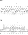
- a V groove base 30 which has a plurality (twelve in the example of Figs. 3 to 5 ) of V grooves 31Ato 31L for arranging optical fibers is provided in the multi-core fusion machine.
- the V grooves 31Ato 31L are generally formed such that a pitch P0 is 0.25 mm in accordance with the international standard of the diameter of the optical fiber.
- Fig. 3 illustrates the fusion process of the intermittently-coupled type optical fiber ribbon of the first reference example in which the optical fibers 11A to 11L having an outer diameter dimension of 0.20mm are arranged in parallel such that a center distance P3 between adjacent optical fibers is 0.25 mm.
- the pitch P0 of the V grooves 31Ato 31L in the V groove base 30 of the multi-core fusion machine is formed to be 0.25 mm.
- the optical fibers 11A to 11L in a state where a predetermined length of tape resin of the tip is removed are arranged above the V groove base 30.
- the optical fibers 11A to 11L are arranged such that the center position 32 of the V groove base 30 in a direction in which the V grooves are arranged in parallel coincides with the center position in a direction in which the optical fibers 11A to 11L are arranged in parallel.
- a clamp lid (not illustrated) of the multi-core fusion machine is closed, and the optical fibers 11A to 11L are pushed down from above by the clamp lid.
- the center distance P3 is formed to be equal to the pitch P0 of the V groove.
- the optical fibers 1 1A to 11L are arranged to face the V grooves 31A to 31L, respectively. For this reason, the optical fibers 11A to 11L are almost vertically pushed down and housed one by one in order in the V grooves 31A to 31L, respectively.
- Fig. 4 illustrates a fusion process of an intermittently-coupled type optical fiber ribbon of a second reference example in which the optical fibers 1 1A to 11L having an outer diameter dimension of 0.20 mm are arranged in parallel such that a center distance P4 of adjacent optical fibers is 0.20 mm.
- the pitch P0 of the V grooves 31Ato 31L in the V groove base 30 is formed to be 0.25 mm.
- the optical fibers 11A to 11L are arranged above the V groove base 30 such that the center positions are aligned similarly to Fig. 3 .
- the clamp lid of the multi-core fusion machine is closed, and the optical fibers 11A to 11L are pushed down from above.
- the center distance P4 of the optical fibers 11A to 11L is formed smaller than the pitch P0 of the V grooves 31A to 31L, and the optical fibers 1 1A to 11L are arranged to gather in the direction of the center position 32 of the V groove base 30. For this reason, the optical fibers 11A to 11L are pushed down along the groove walls of the V grooves in the directions of the arrows, for example. Therefore, the optical fibers 11A to 11L cannot be housed in order in the V grooves 31Ato 31L. For example, in some cases, the optical fiber is not housed in the end V grooves 31A and 31L or the like.
- Fig. 5 illustrates the fusion process of the intermittently-coupled type optical fiber ribbon 1 illustrated in Fig. 2 according to this embodiment.
- the optical fibers 11A to 11L are arranged above the V groove base 30 such that the center positions are aligned similarly to Fig. 3 .
- the clamp lid of the multi-core fusion machine is closed, and the optical fibers 11A to 11L are pushed down from above.
- the center distance P1 between the optical fibers in the dual-core optical fiber ribbon is formed smaller than the pitch P0 of the V groove.
- the center distance P2 of the optical fibers adjacent with the coupling part 13 interposed therebetween between adjacent ribbon type paired optical fibers is formed larger than the pitch P0 of the V groove.
- the optical fibers 11A to 11L are arranged to gather overall in the direction of the center position 32 of the V groove base 30.
- the optical fibers are guided along the groove walls of the V grooves in the directions of the arrows illustrated in Fig. 5 . Accordingly, the optical fibers 11A to 11L are housed one by one in order in the V grooves 31A to 31L, respectively.
- the optical fibers in a state where the tape resins are removed are housed in the V grooves 31Ato 31L.
- the coating layer may be removed in addition to the tape resin, so that only the glass fibers are housed in the V grooves 31A to 31L.
- optical fibers are drawn such that the diameter of the glass fiber 21 is 0.125 mm, and the diameter of the coating layer 22b is 0.20 mm, thereby manufacturing the optical fibers 11A to 11L.
- the coating layer 22b is colored to manufacture the colored optical fibers 11A to 11L.
- the optical fibers 11A to 11L having an outer diameter of about 0.21 mm are manufactured by coloring.
- Twelve optical fibers 11A to 11L are prepared, and optical fibers are passed through a coating die 41 of the manufacturing device 40 in a state where the optical fibers are brought into contact with each other two by two.
- the coating die 41 By the coating die 41, the surfaces of two optical fibers 11A and 11B, 11C and 11D, 11E and 11F, 11G and 11H, 11I and 11J, and 11K and 11L are coated with the tape resins 23 (see Fig. 2 ).
- the optical fibers coated with the tape resins 23 are irradiated by a curing device 42 with ultraviolet rays, and the tape resins 23 are cured. Accordingly, six ribbon type paired optical fibers 12A to 12F in which the center distance P1 of the optical fibers is 0.20 ⁇ 0.03 mm are manufactured.
- the ribbon type paired optical fibers 12A to 12F are arranged in parallel and are passed through a positioning die 43.
- a gap between the ribbon type paired optical fibers is made by the positioning die 43 such that the center distance of adjacent optical fibers between adjacent ribbon type paired optical fibers is 0.28 ⁇ 0.03 mm.
- the coupling resin 15 is intermittently applied between the ribbon type paired optical fibers.
- the coupling resin 15 is applied to the position of the coupling part 13 as illustrated in Fig. 1 .
- the coupling resins 15 are applied between the ribbon type paired optical fibers 12A and 12B, between the ribbon type paired optical fibers 12C and 12D, and between the ribbon type paired optical fibers 12E and 12F.
- the ribbon type paired optical fibers in a state where the coupling resins 15 are applied are arranged in parallel to pass through an extending die 45.
- the coupling resin 15 is pressed vertically by a protrusion part provided in the extending die 45 to extend by a predetermined length (the length of the coupling part 13).
- the ribbon type paired optical fibers in which the coupling resin 15 is extended are irradiated with ultraviolet rays by the curing device 46 to cure the coupling resin 15. Accordingly, the intermittently-coupled type optical fiber ribbon 1 is manufactured completely such that the center distance between the optical fibers included in the dual-core optical fiber ribbon is 0.20 ⁇ 0.03 mm, and the center distance of adjacent optical fibers between adjacent ribbon type paired optical fibers is 0.28 ⁇ 0.03 mm.
- an identification mark 48 may be printed on the optical fiber or the like by an ink jet printer 47.
- the optical fibers 11A to 11L are arranged in the positions corresponding to the V grooves 31Ato 31L, respectively.
- the optical fibers 11A to 11L can be housed one by one in the V grooves 31A to 31L, respectively.
- the ribbon type paired optical fibers 12A to 12F are integrally formed by bringing two optical fibers having an outer diameter dimension R1 of 0.22 mm or less into contact with each other, and are formed such that the center distance P1 between the optical fibers configuring the dual-core optical fiber ribbon is 0.20 ⁇ 0.03 mm.
- the width W1 of the entire intermittently-coupled type optical fiber ribbon 1 in the parallel direction can be narrower than the width of the conventional intermittently-coupled type optical fiber ribbon.
- the cross-sectional area of the intermittently-coupled type optical fiber ribbon 1 can be reduced. Therefore, the density of the optical fiber cable or the optical fiber cord can be increased by using the intermittently-coupled type optical fiber ribbon 1 for the optical fiber cable or the optical fiber cord.
- the thickness T1 of the intermittently-coupled type optical fiber ribbon 1 is suppressed to be 0.26 mm or less, the cross-sectional area can be reduced further, and the density of the optical fiber cable or the optical fiber cord can be increased.
- the coupling part 13 in which adjacent ribbon type paired optical fibers are connected can be formed easily by the coupling resin 15 applied between the ribbon type paired optical fibers.
- the Young's modulus of the inner coating layer 22a of the optical fibers 11A to 11L is 0.5 MPa or less, the deterioration of the lateral pressure characteristic caused by thinning the thickness of the coating layers (22a and 22b) of the optical fibers 11A to 11L can be suppressed.
- the intermittently-coupled type optical fiber ribbon configured such that even the fusion machine in which the pitch of the V groove is set to 0.25 mm can fuse without any problems can be manufactured.
- the dual-core optical fiber ribbon in which the center distance P1 between the optical fibers is 0.20 ⁇ 0.03 mm can be manufactured by the optical fiber having an outer diameter dimension R1 of 0.22 mm or less, and the intermittently-coupled type optical fiber ribbon 1 can be manufactured by applying the coupling resin 15 between the ribbon type paired optical fibers. For this reason, the width W1 of the entire intermittently-coupled type optical fiber ribbon in the parallel direction can be narrowed to reduce the cross-sectional area of the intermittently-coupled type optical fiber ribbon. Accordingly, in a case where the intermittently-coupled type optical fiber ribbon is used for the optical fiber cable or the optical fiber cord, the density of the optical fiber cable or the optical fiber cord can be increased.
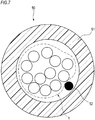
- Fig. 7 is a sectional view illustrating an optical fiber cord 50 using the above-described intermittently-coupled type optical fiber ribbon 1.
- the optical fiber cord 50 has a jacket 51 and the intermittently-coupled type optical fiber ribbon 1.
- the intermittently-coupled type optical fiber ribbon 1 is covered with the cylindrical jacket 51.
- the intermittently-coupled type optical fiber ribbon 1 may be bundled by an intervenient layer 52 made of Kevlar.
- the optical fiber cord 50 can be formed such that the outer diameter is smaller than that of the conventional optical fiber cord.
- the density of the optical fiber cord 50 can be increased compared to the conventional one.
- Fig. 8 is a sectional view illustrating a slot-less optical fiber cable 60 using the above-described intermittently-coupled type optical fiber ribbon 1.
- the optical fiber cable 60 has a cylindrical tube 61 and a plurality of intermittently-coupled type optical fiber ribbons 1.
- the plurality of intermittently-coupled type optical fiber ribbons 1 may be bundled by an intervenient layer 62 such as aramid fibers.
- the plurality of intermittently-coupled type optical fiber ribbons 1 may have markings different from each other.
- the plural bundled intermittently-coupled type optical fiber ribbons 1 are twisted, and a resin to be a tube 61 is extrusion-molded in the periphery thereof.
- the intermittently-coupled type optical fiber ribbons are covered with a jacket 64 together with a tension member 63.
- a water absorptive yarn may be inserted into the tube 61.
- hard materials such as polybutylene terephthalate and high density polyethylene are used as the resin to be the tube 61.
- a tear string 65 may be provided.
- Fig. 9 is a sectional view illustrating a slot optical fiber cable 70 using the above-described intermittently-coupled type optical fiber ribbon 1.
- the optical fiber cable 70 has a slot rod 72 having a plurality of slot grooves 71 and the plurality of intermittently-coupled type optical fiber ribbons 1.
- the optical fiber cable 70 has a structure in which the plurality of slot grooves 71 are radially provided in the slot rod 72 having a tension member 73 at the center.
- the plurality of slot grooves 71 may be provided to be twisted in a spiral shape, a SZ shape, or the like in the longitudinal direction of the optical fiber cable 70.
- Each slot groove 71 houses the plurality of intermittently-coupled type optical fiber ribbons 1 which are disassembled from a parallel state into a dense state.
- Each intermittently-coupled type optical fiber ribbon 1 may be bundled with an identification bundle material.
- a press winding tape 74 is wound around the slot rod 72, and a jacket 75 is formed around the press winding tape 74.
- the cross-sectional area can be made smaller than that of the conventional intermittently-coupled type optical fiber ribbon, the densities of the slot-less optical fiber cable 60 and the slot optical fiber cable 70 can be increased compared to the conventional optical fiber cable.
- the outer diameter can be made smaller than that of the conventional optical fiber cable.
- an intermittently-coupled type optical fiber ribbon 1A according to the modification is not configured to be formed by intermittently applying the coupling resin 15 between the ribbon type paired optical fibers.
- the intermittently-coupled type optical fiber ribbon 1A is formed such that the center distance P2 between every two optical fibers is 0.28 ⁇ 0.03 mm.
- the center distance between the optical fibers 11B and 11C is formed to be 0.28 ⁇ 0.03 mm.
- the center distance between the optical fibers 11A and 11B is formed to be 0.20 ⁇ 0.03 mm.
- the surfaces of twelve optical fibers 11A to 11L arranged in parallel are collectively coated with a tape resin 23A.
- the optical fiber ribbon in which a plurality of cores (twelve cores in Fig. 10 ) are connected to be collectively coated with the tape resin 23A is manufactured such that the center distances of the optical fibers are the above-described values. Further, in the coupling part between the optical fibers formed such that the center distance is 0.28 ⁇ 0.03 mm, for example, cuts (non-coupling part) are intermittently formed in the longitudinal direction by a cutter blade, so as to manufacture the intermittently-coupled type optical fiber ribbon 1A.
- the intermittently-coupled type optical fiber ribbon 1A configured as above exhibits the same effect as the above-described intermittently-coupled type optical fiber ribbon 1.
- an intermittently-coupled type optical fiber ribbon 100 of the first comparative example has a structure in which optical fibers 111 having an outer diameter R2 of 0.25 mm are brought into contact with each other to be arranged in parallel, and a tape resin 123 is applied therearound.
- a pitch P5 between the cores of the intermittently-coupled type optical fiber ribbon 100 is 0.25 mm
- the width W2 of the intermittently-coupled type optical fiber ribbon 100 is 3.04 mm.
- the structure of the optical fiber 111 is a single coated optical fiber having a glass fiber 121 and a coating layer 122 coating the glass fiber 121.
- the intermittently-coupled type optical fiber ribbon 100 When the intermittently-coupled type optical fiber ribbon 100 is simply approximated as an aggregate of the optical fiber, and a thickness T2 of the aggregate is set to 0.285 mm, the cross-sectional area of the intermittently-coupled type optical fiber ribbon 100 is 0.765 mm 2 .
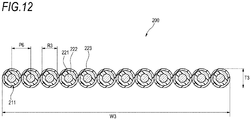
- an intermittently-coupled type optical fiber ribbon 200 of a second comparative example has a structure in which the peripheries of optical fibers 211 having an outer diameter R3 of 0.20 mm are each coated with a tape resin 223, and the optical fibers are arranged in parallel such that a pitch P6 between cores is 0.25 mm.
- the width W3 of the intermittently-coupled type optical fiber ribbon 200 is 3.00 mm.
- the structure of the optical fiber 211 is a single coated optical fiber having a glass fiber 221 and a coating layer 222 coating the glass fiber 221.
- the cross-sectional area of the intermittently-coupled type optical fiber ribbon 200 is 0.589 mm2, which means a reduction rate of about 23% in a cross-sectional area ratio compared to the first comparative example.
- the intermittently-coupled type optical fiber ribbon of the embodiment is formed such that the outer diameter R1 of the optical fibers 11A to 11L is set to 0.20 mm, the pitch P1 between cores is set to 0.20mm, and the pitch P2 is set to 0.28 mm.
- the thickness T1 of the intermittently-coupled type optical fiber ribbon 1 is 0.24 mm, and the width W1 is 2.69 mm.
- the cross-sectional area is 0.543 mm 2 , which means a reduction rate of about 29% in the cross-sectional area ratio compared to the first comparative example.
- the outer diameter of the optical fiber of the first comparative example is typically 0.25 mm
- the outer diameters of the optical fiber of the second comparative example and the embodiment are 0.20 mm smaller than the typical one.
- the cross-sectional area of the intermittently-coupled type optical fiber ribbon of the second comparative example or the embodiment is reduced compared to that of the first comparative example.
- the reduction rate is about 29% in the embodiment, which is larger than about 23% of the second comparative example.
- the sectional area can be reduced compared to the second comparative example which is the conventional intermittently-coupled type optical fiber ribbon.
- problems do not occur during the fusing.
Landscapes
- Physics & Mathematics (AREA)
- General Physics & Mathematics (AREA)
- Optics & Photonics (AREA)
- Engineering & Computer Science (AREA)
- Manufacturing & Machinery (AREA)
- Mechanical Coupling Of Light Guides (AREA)
Applications Claiming Priority (2)
| Application Number | Priority Date | Filing Date | Title |
|---|---|---|---|
| JP2016236568 | 2016-12-06 | ||
| PCT/JP2017/042401 WO2018105424A1 (ja) | 2016-12-06 | 2017-11-27 | 間欠連結型光ファイバテープ心線、その製造方法、光ファイバケーブルおよび光ファイバコード |
Publications (3)
| Publication Number | Publication Date |
|---|---|
| EP3553578A1 true EP3553578A1 (de) | 2019-10-16 |
| EP3553578A4 EP3553578A4 (de) | 2020-08-12 |
| EP3553578B1 EP3553578B1 (de) | 2023-06-07 |
Family
ID=62491136
Family Applications (1)
| Application Number | Title | Priority Date | Filing Date |
|---|---|---|---|
| EP17877839.5A Active EP3553578B1 (de) | 2016-12-06 | 2017-11-27 | Glasfaserbandkern mit sporadischer verbindung, verfahren zur herstellung davon, glasfaserkabel und glasfasercord |
Country Status (5)
| Country | Link |
|---|---|
| US (1) | US20200064550A1 (de) |
| EP (1) | EP3553578B1 (de) |
| JP (1) | JP7052727B2 (de) |
| CN (1) | CN110036325A (de) |
| WO (1) | WO2018105424A1 (de) |
Cited By (1)
| Publication number | Priority date | Publication date | Assignee | Title |
|---|---|---|---|---|
| EP3812817A1 (de) * | 2019-10-21 | 2021-04-28 | Sterlite Technologies Limited | Faseroptisches flachbandkabel mit optischen fasern mit geringem durchmesser |
Families Citing this family (26)
| Publication number | Priority date | Publication date | Assignee | Title |
|---|---|---|---|---|
| US11194108B2 (en) * | 2017-06-14 | 2021-12-07 | Sumitomo Electric Industries, Ltd. | Slot-type optical cable |
| WO2019142841A1 (ja) * | 2018-01-18 | 2019-07-25 | 住友電気工業株式会社 | 光ファイバケーブル |
| WO2020046574A1 (en) | 2018-08-28 | 2020-03-05 | Corning Incorporated | Apparatus and methods for non-contact damping of optical fiber vibration |
| US10801883B2 (en) * | 2018-09-19 | 2020-10-13 | Corning Incorporated | Apparatus and methods for high-speed marking of optical fibers |
| CN111694117A (zh) * | 2019-03-13 | 2020-09-22 | 建毅科技股份有限公司 | 光缆及其布线方法 |
| US20220252809A1 (en) * | 2019-05-28 | 2022-08-11 | Sumitomo Electric Industries, Ltd. | Optical fiber tape core wire, optical fiber cable, and method of manufacturing optical fiber tape core wire |
| JP2020194065A (ja) * | 2019-05-28 | 2020-12-03 | 住友電気工業株式会社 | 光ファイバテープ心線および光ファイバケーブル |
| JP2020204687A (ja) * | 2019-06-17 | 2020-12-24 | 住友電気工業株式会社 | 光ファイバテープ心線、光ファイバケーブルおよび光ファイバテープ心線の製造方法 |
| EP4027180B1 (de) * | 2019-09-05 | 2024-11-06 | Sumitomo Electric Industries, Ltd. | Optisches faserband, optisches faserkabel und mit verbinder versehenes optisches faserkabel |
| CN111175887A (zh) * | 2020-02-13 | 2020-05-19 | 江苏亨通光电股份有限公司 | 光纤带、光缆以及光纤带的制造方法 |
| US11860438B2 (en) | 2020-07-29 | 2024-01-02 | Sumitomo Electric Industries, Ltd. | Method for manufacturing intermittent connection-type optical fiber tape core wire and intermittent connection-type optical fiber tape core wire |
| US20230393350A1 (en) * | 2020-09-14 | 2023-12-07 | Sumitomo Electric Industries, Ltd. | Optical fiber ribbon and method for manufacturing optical fiber ribbon |
| WO2022065485A1 (ja) * | 2020-09-28 | 2022-03-31 | 住友電気工業株式会社 | 光ファイバケーブルおよびコネクタ付きケーブル |
| EP4231073B1 (de) * | 2020-10-19 | 2026-01-28 | Sumitomo Electric Industries, Ltd. | Optisches faserband |
| US12386129B2 (en) * | 2020-10-19 | 2025-08-12 | Sumitomo Electric Industries, Ltd. | Optical fiber ribbon |
| US11442238B2 (en) * | 2020-12-22 | 2022-09-13 | Prysmian S.P.A. | Optical-fiber ribbon with spaced optical-fiber units |
| JP2022183873A (ja) * | 2021-05-31 | 2022-12-13 | 住友電気工業株式会社 | 光ファイバリボン |
| US20230168441A1 (en) * | 2021-11-30 | 2023-06-01 | Corning Research & Development Corporation | Unjacketed fiber optic cable assembly, and cable assembly including connector with travel limited ferrule |
| US20240353639A1 (en) * | 2021-12-10 | 2024-10-24 | Sumitomo Electric Industries, Ltd. | Optical fiber cable and method for manufacturing optical fiber cable |
| CN114217397B (zh) * | 2021-12-20 | 2023-03-21 | 长飞光纤光缆股份有限公司 | 光纤带的成型方法及专用于实施该成型方法的点胶设备 |
| JPWO2024014487A1 (de) * | 2022-07-13 | 2024-01-18 | ||
| WO2024014488A1 (ja) * | 2022-07-13 | 2024-01-18 | 住友電気工業株式会社 | 光ファイバリボンおよび光ケーブル |
| CN115542481A (zh) * | 2022-08-08 | 2022-12-30 | 富通特种光缆(天津)有限公司 | 一种网状光纤带骨架缆及其熔接方法 |
| WO2024042726A1 (ja) * | 2022-08-26 | 2024-02-29 | Swcc株式会社 | 光ファイバテープ心線およびスロットレス型光ケーブル |
| EP4703782A1 (de) * | 2023-04-24 | 2026-03-04 | Sumitomo Electric Industries, Ltd. | Optisches faserband |
| WO2025263437A1 (ja) * | 2024-06-17 | 2025-12-26 | 住友電気工業株式会社 | 光ファイバテープ心線および光ファイバテープ心線の製造方法 |
Family Cites Families (17)
| Publication number | Priority date | Publication date | Assignee | Title |
|---|---|---|---|---|
| US6859600B2 (en) | 2002-05-30 | 2005-02-22 | Alcatel | Coated optical fiber and optical fiber ribbon and method for the fabrication thereof |
| JP3664254B2 (ja) | 2002-11-06 | 2005-06-22 | 住友電気工業株式会社 | 光ファイバテープ心線及びその製造方法 |
| JP4980841B2 (ja) * | 2007-10-11 | 2012-07-18 | 株式会社フジクラ | 光ファイバテープ心線およびその分割方法 |
| JP5697011B2 (ja) | 2010-02-16 | 2015-04-08 | 古河電気工業株式会社 | 光ファイバケーブル、及び光ファイバケーブルの形成方法 |
| JP2011232733A (ja) * | 2010-04-07 | 2011-11-17 | Sumitomo Electric Ind Ltd | 光ファイバテープ心線、光ファイバケーブル、及び光ファイバテープ心線の製造方法 |
| JP2011232722A (ja) | 2010-04-28 | 2011-11-17 | Terajima Shigeru | 特殊プリズム計算方法 |
| JP5564026B2 (ja) * | 2011-10-18 | 2014-07-30 | 株式会社フジクラ | 光ファイバテープ心線及びその光ファイバテープ心線を収納した光ファイバケーブル |
| JP5294357B2 (ja) | 2012-02-15 | 2013-09-18 | 古河電気工業株式会社 | 光ファイバ着色心線、光ファイバテープ心線及び光ファイバケーブル |
| JP5450687B2 (ja) * | 2012-02-15 | 2014-03-26 | 昭和電線ケーブルシステム株式会社 | 光ファイバテープ心線の製造方法および光ファイバテープ心線の製造装置 |
| JP5651740B2 (ja) * | 2013-06-17 | 2015-01-14 | 日本電信電話株式会社 | 光ファイバテープおよび光ファイバケーブル |
| JP2015007714A (ja) | 2013-06-25 | 2015-01-15 | 住友電気工業株式会社 | 光ファイバテープ心線、光ケーブル、製造装置、及び製造方法 |
| JP5802309B2 (ja) * | 2014-06-06 | 2015-10-28 | 株式会社フジクラ | 光ファイバテープ心線及びその光ファイバテープ心線を収納した光ファイバケーブル |
| JP6270648B2 (ja) * | 2014-07-15 | 2018-01-31 | 住友電気工業株式会社 | 光ケーブル用のスロットロッド及び光ケーブル |
| JP2016075746A (ja) * | 2014-10-03 | 2016-05-12 | 住友電気工業株式会社 | 間欠型光ファイバテープ心線及びその製造方法 |
| DK3207415T3 (en) * | 2014-10-14 | 2019-03-18 | Prysmian Spa | Centrally loose-tube optical fiber cable |
| JP6620749B2 (ja) * | 2014-12-03 | 2019-12-18 | 住友電気工業株式会社 | 光ファイバ心線及び光ファイバテープ心線 |
| JP6453970B1 (ja) * | 2017-10-05 | 2019-01-16 | 株式会社フジクラ | 間欠連結型光ファイバテープ、及び、間欠連結型光ファイバテープの製造方法 |
-
2017
- 2017-11-27 JP JP2018554926A patent/JP7052727B2/ja active Active
- 2017-11-27 WO PCT/JP2017/042401 patent/WO2018105424A1/ja not_active Ceased
- 2017-11-27 CN CN201780075321.XA patent/CN110036325A/zh active Pending
- 2017-11-27 US US16/466,689 patent/US20200064550A1/en not_active Abandoned
- 2017-11-27 EP EP17877839.5A patent/EP3553578B1/de active Active
Cited By (1)
| Publication number | Priority date | Publication date | Assignee | Title |
|---|---|---|---|---|
| EP3812817A1 (de) * | 2019-10-21 | 2021-04-28 | Sterlite Technologies Limited | Faseroptisches flachbandkabel mit optischen fasern mit geringem durchmesser |
Also Published As
| Publication number | Publication date |
|---|---|
| EP3553578A4 (de) | 2020-08-12 |
| EP3553578B1 (de) | 2023-06-07 |
| WO2018105424A1 (ja) | 2018-06-14 |
| JP7052727B2 (ja) | 2022-04-12 |
| CN110036325A (zh) | 2019-07-19 |
| JPWO2018105424A1 (ja) | 2019-10-24 |
| US20200064550A1 (en) | 2020-02-27 |
Similar Documents
| Publication | Publication Date | Title |
|---|---|---|
| EP3553578B1 (de) | Glasfaserbandkern mit sporadischer verbindung, verfahren zur herstellung davon, glasfaserkabel und glasfasercord | |
| JP4055000B2 (ja) | 光ファイバケーブル、光ファイバケーブルの製造方法及び光ファイバケーブルの製造装置 | |
| EP3410167B1 (de) | Glasfaserkabel | |
| EP3705923B1 (de) | Glasfasereinheit und glasfaserkabel | |
| CN108463757A (zh) | 间断性连结型光纤带芯线、光缆、及间断性连结型光纤带芯线的制法 | |
| JP6362302B2 (ja) | 光ファイバテープ心線及び光ケーブル | |
| CN108474921A (zh) | 间断性连结型光纤带芯线、间断性连结型光纤带芯线的制造方法、光缆及光纤软线 | |
| CN101027588A (zh) | 具有一个或多个优先破裂部分的光纤带及其制造方法 | |
| CN106932870A (zh) | 光纤带芯线及收纳该光纤带芯线的光纤线缆 | |
| EP3705924B1 (de) | Glasfasereinheit und glasfaserkabel | |
| EP3923052B1 (de) | Ein intermittierend gekoppeltes optisches faserband und ein verfahren zu seiner herstellung | |
| JP2011232733A (ja) | 光ファイバテープ心線、光ファイバケーブル、及び光ファイバテープ心線の製造方法 | |
| JP2020024257A (ja) | 光ファイバテープ心線、光ファイバケーブル、および光ファイバテープ心線の融着接続方法 | |
| JP2013109172A (ja) | 光ファイバユニット及び光ケーブル | |
| US11249272B2 (en) | Optical fiber cable and manufacturing method of optical fiber cable | |
| KR20200106570A (ko) | 광섬유 유닛 및 광섬유 케이블 | |
| US11435543B2 (en) | Optical fiber unit and optical fiber cable | |
| WO2005101080A1 (ja) | 光ファイバテープユニット及び光ファイバケーブル | |
| US20250164733A1 (en) | Optical fiber cable, optical fiber ribbon, method of installing optical fiber cable, and optical transmission system | |
| US11906803B2 (en) | Optical fiber ribbon with intermittently coupled groups of fibers | |
| EP4556977A1 (de) | Glasfaserband und optisches kabel | |
| JP6323411B2 (ja) | 光ファイバテープ心線および光ファイバケーブル | |
| JP2005321419A (ja) | 光ファイバテープユニット及び光ファイバケーブル | |
| JPH08171033A (ja) | スペーサ形光ファイバケーブル | |
| JPH06273647A (ja) | 多心テープ心線用ジャンパテープ |
Legal Events
| Date | Code | Title | Description |
|---|---|---|---|
| STAA | Information on the status of an ep patent application or granted ep patent |
Free format text: STATUS: THE INTERNATIONAL PUBLICATION HAS BEEN MADE |
|
| PUAI | Public reference made under article 153(3) epc to a published international application that has entered the european phase |
Free format text: ORIGINAL CODE: 0009012 |
|
| STAA | Information on the status of an ep patent application or granted ep patent |
Free format text: STATUS: REQUEST FOR EXAMINATION WAS MADE |
|
| 17P | Request for examination filed |
Effective date: 20190606 |
|
| AK | Designated contracting states |
Kind code of ref document: A1 Designated state(s): AL AT BE BG CH CY CZ DE DK EE ES FI FR GB GR HR HU IE IS IT LI LT LU LV MC MK MT NL NO PL PT RO RS SE SI SK SM TR |
|
| AX | Request for extension of the european patent |
Extension state: BA ME |
|
| DAV | Request for validation of the european patent (deleted) | ||
| DAX | Request for extension of the european patent (deleted) | ||
| A4 | Supplementary search report drawn up and despatched |
Effective date: 20200709 |
|
| RIC1 | Information provided on ipc code assigned before grant |
Ipc: G02B 6/44 20060101AFI20200704BHEP |
|
| STAA | Information on the status of an ep patent application or granted ep patent |
Free format text: STATUS: EXAMINATION IS IN PROGRESS |
|
| 17Q | First examination report despatched |
Effective date: 20210625 |
|
| GRAP | Despatch of communication of intention to grant a patent |
Free format text: ORIGINAL CODE: EPIDOSNIGR1 |
|
| STAA | Information on the status of an ep patent application or granted ep patent |
Free format text: STATUS: GRANT OF PATENT IS INTENDED |
|
| INTG | Intention to grant announced |
Effective date: 20230118 |
|
| GRAS | Grant fee paid |
Free format text: ORIGINAL CODE: EPIDOSNIGR3 |
|
| GRAA | (expected) grant |
Free format text: ORIGINAL CODE: 0009210 |
|
| STAA | Information on the status of an ep patent application or granted ep patent |
Free format text: STATUS: THE PATENT HAS BEEN GRANTED |
|
| AK | Designated contracting states |
Kind code of ref document: B1 Designated state(s): AL AT BE BG CH CY CZ DE DK EE ES FI FR GB GR HR HU IE IS IT LI LT LU LV MC MK MT NL NO PL PT RO RS SE SI SK SM TR |
|
| REG | Reference to a national code |
Ref country code: GB Ref legal event code: FG4D |
|
| REG | Reference to a national code |
Ref country code: CH Ref legal event code: EP Ref country code: AT Ref legal event code: REF Ref document number: 1576829 Country of ref document: AT Kind code of ref document: T Effective date: 20230615 |
|
| P01 | Opt-out of the competence of the unified patent court (upc) registered |
Effective date: 20230515 |
|
| REG | Reference to a national code |
Ref country code: DE Ref legal event code: R096 Ref document number: 602017069993 Country of ref document: DE |
|
| REG | Reference to a national code |
Ref country code: LT Ref legal event code: MG9D |
|
| REG | Reference to a national code |
Ref country code: NL Ref legal event code: MP Effective date: 20230607 |
|
| PG25 | Lapsed in a contracting state [announced via postgrant information from national office to epo] |
Ref country code: SE Free format text: LAPSE BECAUSE OF FAILURE TO SUBMIT A TRANSLATION OF THE DESCRIPTION OR TO PAY THE FEE WITHIN THE PRESCRIBED TIME-LIMIT Effective date: 20230607 Ref country code: NO Free format text: LAPSE BECAUSE OF FAILURE TO SUBMIT A TRANSLATION OF THE DESCRIPTION OR TO PAY THE FEE WITHIN THE PRESCRIBED TIME-LIMIT Effective date: 20230907 Ref country code: ES Free format text: LAPSE BECAUSE OF FAILURE TO SUBMIT A TRANSLATION OF THE DESCRIPTION OR TO PAY THE FEE WITHIN THE PRESCRIBED TIME-LIMIT Effective date: 20230607 |
|
| REG | Reference to a national code |
Ref country code: AT Ref legal event code: MK05 Ref document number: 1576829 Country of ref document: AT Kind code of ref document: T Effective date: 20230607 |
|
| PG25 | Lapsed in a contracting state [announced via postgrant information from national office to epo] |
Ref country code: RS Free format text: LAPSE BECAUSE OF FAILURE TO SUBMIT A TRANSLATION OF THE DESCRIPTION OR TO PAY THE FEE WITHIN THE PRESCRIBED TIME-LIMIT Effective date: 20230607 Ref country code: NL Free format text: LAPSE BECAUSE OF FAILURE TO SUBMIT A TRANSLATION OF THE DESCRIPTION OR TO PAY THE FEE WITHIN THE PRESCRIBED TIME-LIMIT Effective date: 20230607 Ref country code: LV Free format text: LAPSE BECAUSE OF FAILURE TO SUBMIT A TRANSLATION OF THE DESCRIPTION OR TO PAY THE FEE WITHIN THE PRESCRIBED TIME-LIMIT Effective date: 20230607 Ref country code: LT Free format text: LAPSE BECAUSE OF FAILURE TO SUBMIT A TRANSLATION OF THE DESCRIPTION OR TO PAY THE FEE WITHIN THE PRESCRIBED TIME-LIMIT Effective date: 20230607 Ref country code: HR Free format text: LAPSE BECAUSE OF FAILURE TO SUBMIT A TRANSLATION OF THE DESCRIPTION OR TO PAY THE FEE WITHIN THE PRESCRIBED TIME-LIMIT Effective date: 20230607 Ref country code: GR Free format text: LAPSE BECAUSE OF FAILURE TO SUBMIT A TRANSLATION OF THE DESCRIPTION OR TO PAY THE FEE WITHIN THE PRESCRIBED TIME-LIMIT Effective date: 20230908 |
|
| PG25 | Lapsed in a contracting state [announced via postgrant information from national office to epo] |
Ref country code: FI Free format text: LAPSE BECAUSE OF FAILURE TO SUBMIT A TRANSLATION OF THE DESCRIPTION OR TO PAY THE FEE WITHIN THE PRESCRIBED TIME-LIMIT Effective date: 20230607 |
|
| PG25 | Lapsed in a contracting state [announced via postgrant information from national office to epo] |
Ref country code: SK Free format text: LAPSE BECAUSE OF FAILURE TO SUBMIT A TRANSLATION OF THE DESCRIPTION OR TO PAY THE FEE WITHIN THE PRESCRIBED TIME-LIMIT Effective date: 20230607 |
|
| PG25 | Lapsed in a contracting state [announced via postgrant information from national office to epo] |
Ref country code: IS Free format text: LAPSE BECAUSE OF FAILURE TO SUBMIT A TRANSLATION OF THE DESCRIPTION OR TO PAY THE FEE WITHIN THE PRESCRIBED TIME-LIMIT Effective date: 20231007 |
|
| PG25 | Lapsed in a contracting state [announced via postgrant information from national office to epo] |
Ref country code: SM Free format text: LAPSE BECAUSE OF FAILURE TO SUBMIT A TRANSLATION OF THE DESCRIPTION OR TO PAY THE FEE WITHIN THE PRESCRIBED TIME-LIMIT Effective date: 20230607 Ref country code: SK Free format text: LAPSE BECAUSE OF FAILURE TO SUBMIT A TRANSLATION OF THE DESCRIPTION OR TO PAY THE FEE WITHIN THE PRESCRIBED TIME-LIMIT Effective date: 20230607 Ref country code: RO Free format text: LAPSE BECAUSE OF FAILURE TO SUBMIT A TRANSLATION OF THE DESCRIPTION OR TO PAY THE FEE WITHIN THE PRESCRIBED TIME-LIMIT Effective date: 20230607 Ref country code: PT Free format text: LAPSE BECAUSE OF FAILURE TO SUBMIT A TRANSLATION OF THE DESCRIPTION OR TO PAY THE FEE WITHIN THE PRESCRIBED TIME-LIMIT Effective date: 20231009 Ref country code: IS Free format text: LAPSE BECAUSE OF FAILURE TO SUBMIT A TRANSLATION OF THE DESCRIPTION OR TO PAY THE FEE WITHIN THE PRESCRIBED TIME-LIMIT Effective date: 20231007 Ref country code: EE Free format text: LAPSE BECAUSE OF FAILURE TO SUBMIT A TRANSLATION OF THE DESCRIPTION OR TO PAY THE FEE WITHIN THE PRESCRIBED TIME-LIMIT Effective date: 20230607 Ref country code: CZ Free format text: LAPSE BECAUSE OF FAILURE TO SUBMIT A TRANSLATION OF THE DESCRIPTION OR TO PAY THE FEE WITHIN THE PRESCRIBED TIME-LIMIT Effective date: 20230607 Ref country code: AT Free format text: LAPSE BECAUSE OF FAILURE TO SUBMIT A TRANSLATION OF THE DESCRIPTION OR TO PAY THE FEE WITHIN THE PRESCRIBED TIME-LIMIT Effective date: 20230607 |
|
| PG25 | Lapsed in a contracting state [announced via postgrant information from national office to epo] |
Ref country code: PL Free format text: LAPSE BECAUSE OF FAILURE TO SUBMIT A TRANSLATION OF THE DESCRIPTION OR TO PAY THE FEE WITHIN THE PRESCRIBED TIME-LIMIT Effective date: 20230607 |
|
| REG | Reference to a national code |
Ref country code: DE Ref legal event code: R097 Ref document number: 602017069993 Country of ref document: DE |
|
| PLBE | No opposition filed within time limit |
Free format text: ORIGINAL CODE: 0009261 |
|
| STAA | Information on the status of an ep patent application or granted ep patent |
Free format text: STATUS: NO OPPOSITION FILED WITHIN TIME LIMIT |
|
| PG25 | Lapsed in a contracting state [announced via postgrant information from national office to epo] |
Ref country code: DK Free format text: LAPSE BECAUSE OF FAILURE TO SUBMIT A TRANSLATION OF THE DESCRIPTION OR TO PAY THE FEE WITHIN THE PRESCRIBED TIME-LIMIT Effective date: 20230607 |
|
| PG25 | Lapsed in a contracting state [announced via postgrant information from national office to epo] |
Ref country code: SI Free format text: LAPSE BECAUSE OF FAILURE TO SUBMIT A TRANSLATION OF THE DESCRIPTION OR TO PAY THE FEE WITHIN THE PRESCRIBED TIME-LIMIT Effective date: 20230607 |
|
| 26N | No opposition filed |
Effective date: 20240308 |
|
| PG25 | Lapsed in a contracting state [announced via postgrant information from national office to epo] |
Ref country code: SI Free format text: LAPSE BECAUSE OF FAILURE TO SUBMIT A TRANSLATION OF THE DESCRIPTION OR TO PAY THE FEE WITHIN THE PRESCRIBED TIME-LIMIT Effective date: 20230607 Ref country code: IT Free format text: LAPSE BECAUSE OF FAILURE TO SUBMIT A TRANSLATION OF THE DESCRIPTION OR TO PAY THE FEE WITHIN THE PRESCRIBED TIME-LIMIT Effective date: 20230607 |
|
| REG | Reference to a national code |
Ref country code: CH Ref legal event code: PL |
|
| PG25 | Lapsed in a contracting state [announced via postgrant information from national office to epo] |
Ref country code: MC Free format text: LAPSE BECAUSE OF FAILURE TO SUBMIT A TRANSLATION OF THE DESCRIPTION OR TO PAY THE FEE WITHIN THE PRESCRIBED TIME-LIMIT Effective date: 20230607 |
|
| PG25 | Lapsed in a contracting state [announced via postgrant information from national office to epo] |
Ref country code: LU Free format text: LAPSE BECAUSE OF NON-PAYMENT OF DUE FEES Effective date: 20231127 |
|
| PG25 | Lapsed in a contracting state [announced via postgrant information from national office to epo] |
Ref country code: CH Free format text: LAPSE BECAUSE OF NON-PAYMENT OF DUE FEES Effective date: 20231130 |
|
| PG25 | Lapsed in a contracting state [announced via postgrant information from national office to epo] |
Ref country code: MC Free format text: LAPSE BECAUSE OF FAILURE TO SUBMIT A TRANSLATION OF THE DESCRIPTION OR TO PAY THE FEE WITHIN THE PRESCRIBED TIME-LIMIT Effective date: 20230607 Ref country code: LU Free format text: LAPSE BECAUSE OF NON-PAYMENT OF DUE FEES Effective date: 20231127 Ref country code: CH Free format text: LAPSE BECAUSE OF NON-PAYMENT OF DUE FEES Effective date: 20231130 |
|
| REG | Reference to a national code |
Ref country code: BE Ref legal event code: MM Effective date: 20231130 |
|
| REG | Reference to a national code |
Ref country code: IE Ref legal event code: MM4A |
|
| PG25 | Lapsed in a contracting state [announced via postgrant information from national office to epo] |
Ref country code: IE Free format text: LAPSE BECAUSE OF NON-PAYMENT OF DUE FEES Effective date: 20231127 |
|
| PG25 | Lapsed in a contracting state [announced via postgrant information from national office to epo] |
Ref country code: BE Free format text: LAPSE BECAUSE OF NON-PAYMENT OF DUE FEES Effective date: 20231130 |
|
| PG25 | Lapsed in a contracting state [announced via postgrant information from national office to epo] |
Ref country code: IE Free format text: LAPSE BECAUSE OF NON-PAYMENT OF DUE FEES Effective date: 20231127 Ref country code: BE Free format text: LAPSE BECAUSE OF NON-PAYMENT OF DUE FEES Effective date: 20231130 |
|
| PG25 | Lapsed in a contracting state [announced via postgrant information from national office to epo] |
Ref country code: BG Free format text: LAPSE BECAUSE OF FAILURE TO SUBMIT A TRANSLATION OF THE DESCRIPTION OR TO PAY THE FEE WITHIN THE PRESCRIBED TIME-LIMIT Effective date: 20230607 |
|
| PG25 | Lapsed in a contracting state [announced via postgrant information from national office to epo] |
Ref country code: BG Free format text: LAPSE BECAUSE OF FAILURE TO SUBMIT A TRANSLATION OF THE DESCRIPTION OR TO PAY THE FEE WITHIN THE PRESCRIBED TIME-LIMIT Effective date: 20230607 |
|
| PG25 | Lapsed in a contracting state [announced via postgrant information from national office to epo] |
Ref country code: CY Free format text: LAPSE BECAUSE OF FAILURE TO SUBMIT A TRANSLATION OF THE DESCRIPTION OR TO PAY THE FEE WITHIN THE PRESCRIBED TIME-LIMIT; INVALID AB INITIO Effective date: 20171127 |
|
| PG25 | Lapsed in a contracting state [announced via postgrant information from national office to epo] |
Ref country code: HU Free format text: LAPSE BECAUSE OF FAILURE TO SUBMIT A TRANSLATION OF THE DESCRIPTION OR TO PAY THE FEE WITHIN THE PRESCRIBED TIME-LIMIT; INVALID AB INITIO Effective date: 20171127 |
|
| PGFP | Annual fee paid to national office [announced via postgrant information from national office to epo] |
Ref country code: FR Payment date: 20250930 Year of fee payment: 9 |
|
| PG25 | Lapsed in a contracting state [announced via postgrant information from national office to epo] |
Ref country code: TR Free format text: LAPSE BECAUSE OF FAILURE TO SUBMIT A TRANSLATION OF THE DESCRIPTION OR TO PAY THE FEE WITHIN THE PRESCRIBED TIME-LIMIT Effective date: 20230607 |
|
| PGFP | Annual fee paid to national office [announced via postgrant information from national office to epo] |
Ref country code: DE Payment date: 20250930 Year of fee payment: 9 |
|
| PGFP | Annual fee paid to national office [announced via postgrant information from national office to epo] |
Ref country code: GB Payment date: 20251001 Year of fee payment: 9 |