WO2019142841A1 - 光ファイバケーブル - Google Patents
光ファイバケーブル Download PDFInfo
- Publication number
- WO2019142841A1 WO2019142841A1 PCT/JP2019/001173 JP2019001173W WO2019142841A1 WO 2019142841 A1 WO2019142841 A1 WO 2019142841A1 JP 2019001173 W JP2019001173 W JP 2019001173W WO 2019142841 A1 WO2019142841 A1 WO 2019142841A1
- Authority
- WO
- WIPO (PCT)
- Prior art keywords
- optical fiber
- slot
- core
- cable
- tube
- Prior art date
Links
Images


Classifications
-
- G—PHYSICS
- G02—OPTICS
- G02B—OPTICAL ELEMENTS, SYSTEMS OR APPARATUS
- G02B6/00—Light guides; Structural details of arrangements comprising light guides and other optical elements, e.g. couplings
- G02B6/44—Mechanical structures for providing tensile strength and external protection for fibres, e.g. optical transmission cables
- G02B6/4401—Optical cables
- G02B6/4407—Optical cables with internal fluted support member
-
- G—PHYSICS
- G02—OPTICS
- G02B—OPTICAL ELEMENTS, SYSTEMS OR APPARATUS
- G02B6/00—Light guides; Structural details of arrangements comprising light guides and other optical elements, e.g. couplings
- G02B6/44—Mechanical structures for providing tensile strength and external protection for fibres, e.g. optical transmission cables
- G02B6/4401—Optical cables
- G02B6/4405—Optical cables with longitudinally spaced waveguide clamping
-
- G—PHYSICS
- G02—OPTICS
- G02B—OPTICAL ELEMENTS, SYSTEMS OR APPARATUS
- G02B6/00—Light guides; Structural details of arrangements comprising light guides and other optical elements, e.g. couplings
- G02B6/44—Mechanical structures for providing tensile strength and external protection for fibres, e.g. optical transmission cables
- G02B6/4401—Optical cables
- G02B6/4407—Optical cables with internal fluted support member
- G02B6/4409—Optical cables with internal fluted support member for ribbons
-
- G—PHYSICS
- G02—OPTICS
- G02B—OPTICAL ELEMENTS, SYSTEMS OR APPARATUS
- G02B6/00—Light guides; Structural details of arrangements comprising light guides and other optical elements, e.g. couplings
- G02B6/44—Mechanical structures for providing tensile strength and external protection for fibres, e.g. optical transmission cables
- G02B6/4401—Optical cables
- G02B6/4403—Optical cables with ribbon structure
- G02B6/4404—Multi-podded
Definitions
- the present disclosure relates to fiber optic cables.
- This application claims priority based on Japanese Patent Application No. 2018-006300 filed on Jan. 18, 2018, and incorporates the entire contents described in the aforementioned Japanese application.
- Patent Document 1 describes an optical fiber cable including an optical fiber ribbon in a pipe.
- Patent Document 2 describes an optical fiber unit in which a plurality of optical fiber cores are bundled.
- Patent Document 3 a slot core in which a slot groove for housing an optical fiber is formed on the outer peripheral surface along the cable longitudinal direction, and a press-winding tape wound around the entire outer peripheral surface of the slot core so as to cover the slot groove;
- a fiber optic cable is described having a press-winding tape and a sheath covering the slotted core.
- the optical fiber cable according to one aspect of the present disclosure is An optical fiber cable comprising: a plurality of ribs formed along the longitudinal direction of the cable; and a slot core having a slot groove for accommodating an optical fiber between the ribs. Between some or all of the optical fibers, a connecting portion in which adjacent optical fibers are connected and an unconnected portion in which adjacent optical fibers are not connected are intermittently interrupted.
- a subunit formed by bundling a plurality of intermittently coupled optical fiber ribbons A thin tube having a lower Young's modulus than the material forming the slot core, Have The subunit is housed in the slot groove, Among the subunits in the slot groove, at least the subunit located on the outer periphery of the slot groove is covered by the tube.
- a winding such as coarse winding or a water absorption tape is applied around the outer periphery of the slot groove.
- this winding is wound on the slot core under tension, the cable is deformed into a polygonal shape so that the space for the optical fiber to be inside the straight line connecting the rib apexes of the slots. For this reason, the space which can accommodate an optical fiber core line is restricted. This is a limitation in increasing the number of cores and increasing the density of the optical fiber cable.
- the present disclosure is directed to providing a multicore, high density fiber optic cable.
- the optical fiber cable according to one aspect of the present disclosure is (1) An optical fiber cable comprising: a plurality of ribs formed along the longitudinal direction of the cable; and a slot core having a slot groove for accommodating an optical fiber between the ribs, Between some or all of the optical fibers, a connecting portion in which adjacent optical fibers are connected and an unconnected portion in which adjacent optical fibers are not connected are intermittently interrupted.
- a subunit formed by bundling a plurality of intermittently coupled optical fiber ribbons A thin tube having a lower Young's modulus than the material forming the slot core, Have The subunit is housed in the slot groove, Among the subunits in the slot groove, at least the subunit located on the outer periphery of the slot groove is covered by the tube. According to the above configuration, since the sub-units located on the outer periphery of the slot groove are covered with the thin-skinned tube having a Young's modulus lower than that of the material forming the slot core, coarse winding or water absorption is performed on the outer periphery of the slot groove. It is not necessary to hold back the tape or the like. For this reason, since there is no deformation of the cable due to rough winding or press-winding, there is no restriction of the optical fiber accommodation space due to this deformation, and it is possible to provide a multi-core high density optical fiber cable.
- the number of optical fibers accommodated in one slot groove may be 288 or more. According to the above configuration, it is possible to provide a multi-core optical fiber cable in which the number of optical fibers accommodated in one slot groove is 288 or more.
- h be the length of the root portion of the rib defined by the line connecting the bottom portions of the slot grooves, and the distance between the root portion and the apex of the rib by a straight line be the rib height h
- h / t may be 4 or more and 8 or less. According to the above configuration, by making h / t 4 or more, the rib becomes thin, and more optical fibers can be accommodated in the slot groove. In addition, since h / t is 8 or less, the strength of the rib can be secured to some extent, and the rib is not easily deformed.
- At least the outermost layer portion of the slot core may be formed of an engineering plastic. According to the above configuration, since at least the outermost layer portion of the slot core is formed of an engineering plastic which is a relatively hard material, the strength of the slot core can be increased.
- the water absorption yarn may be provided in the tube. According to the above configuration, since the water absorbing yarn is contained in the tube, the tube can be provided with a waterproof function.
- the core density of the optical fiber housed in the optical fiber cable may be 5.0 cores / mm 2 or more. According to the above configuration, it is possible to provide a high-density optical fiber cable having a core density of 5.0 cores / mm 2 or more.
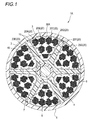
- FIG. 1 is a cross-sectional view perpendicular to the longitudinal direction of the optical fiber cable according to the first embodiment of the present disclosure.
- the optical fiber cable 1A of the first embodiment includes a slot core 4 having a plurality of (six in this example) ribs 2 and a slot groove 3 provided between the ribs 2 Slot type cable.
- the rib 2 and the slot groove 3 are formed, for example, in a spiral or SZ shape along the longitudinal direction (longitudinal direction) of the optical fiber cable 1A.
- subunits 20 formed by bundling a plurality of optical fiber ribbons 10 are accommodated along the longitudinal direction of the optical fiber cable 1A.
- seven sub-units 20 (20A to 20G) are accommodated in one slot groove 3, for example.
- 18 optical fiber ribbons 10 are bundled in one subunit.
- the eighteen optical fiber ribbons 10 constituting each of the subunits 20A to 20G are twisted together and assembled.
- Each of the subunits 20A to 20G may be wound with, for example, a bundle material (not shown) so that the twisted optical fiber ribbons 10 do not break apart.
- the bundle material may be a distinctive colored bundle material.
- the seven subunits 20 (20A to 20G) may be spirally wound with, for example, a roughly wound yarn (not shown) so as to form one assembly.
- the whole of the seven subunits 20A to 20G housed in each slot groove 3 is covered with a thin tube 30A on the outer periphery.
- the thickness of the tube 30A is about 0.3 mm.
- the tube 30A is made of, for example, a plastic resin such as low density polyethylene (PE) or polyvinyl chloride (PVC).
- the Young's modulus of the resin forming the tube 30A is lower than, for example, the Young's modulus of the material forming the slot core 4.
- the tube 30A can be easily elastically deformed. The material of the slot core 4 will be described later.
- an opening may be formed, for example, by interrupting a part in the circumferential direction, in order to facilitate removal of the internal subunits 20A to 20G.
- the opening is formed, for example, in a spiral shape along the longitudinal direction of the subunit 20.
- a water absorbing yarn 40 having a waterproof function may be provided in the tube 30A.
- the water absorbing yarn 40 is, for example, a linear member having an outer diameter of about 0.1 mm in a dry state, and is provided along the longitudinal direction of the optical fiber cable 1A.
- a jacket 5 is provided on the outer periphery of the slot core 4 so as to cover the slot groove 3.
- the jacket 5 is formed of, for example, a resin such as polyethylene (PE).
- PE polyethylene
- the jacket 5 is formed around the slot core 4 by extruding a resin.
- the jacket 5 is provided in direct contact with a tube 30A that covers the subunits 20A to 20G.
- a tension member 6 formed of a steel wire or the like is embedded along the longitudinal direction of the optical fiber cable 1A.
- the slot core 4 has a two-layer structure having a first layer portion 7 provided on the outer periphery of the tension member 6 and a second layer portion 8 (an example of the outermost layer portion) provided on the outer periphery of the first layer portion 7. It is formed.
- the first layer portion 7 is provided as an adhesive layer for bonding the tension member 6 and the second layer portion 8.
- the first layer portion 7 is formed of, for example, a resin having a relatively low Young's modulus, such as an ethylene-methacrylic acid copolymer.
- the second layer portion 8 is a layer forming a portion outside the first layer portion 7, and the rib 2 is also included in the second layer portion 8.
- the second layer portion 8 is formed of, for example, an engineering plastic having a relatively high Young's modulus, such as polybutylene terephthalate (PBT).
- PBT polybutylene terephthalate
- the number of ribs 2 constituting the slot core 4 be small, that is, the number of slot grooves 3 be small. Therefore, in the optical fiber cable 1A, the number of slot grooves 3 in the slot core 4 is set to six or less.
- the volume occupied by the ribs 2 in the slot core 4 be small, that is, the thickness (thickness) of each rib 2 be thin (thin). Therefore, in the optical fiber cable 1A, as shown in FIG. 1, the length of the root portion of the rib 2 defined by the line connecting the bottom portions of adjacent slot grooves 3 is t, and the apex of the rib 2 from the root portion When the distance h connecting the straight lines is a height h of the rib 2, h / t is set to 4 or more and 8 or less.
- the bottom of the slot groove 3 means the bottom point B closest to the center point X of the slot core 4 in the slot groove 3 having a round bottom as shown in FIG.
- the ribs 2 become thinner, and more optical fibers can be accommodated in the slot groove 3.
- the strength of the rib can be secured to some extent, and the rib is not easily deformed.
- the second layer portion 8 of the slot core 4 is formed of an engineering plastic having a high Young's modulus.
- FIG. 2 shows an example of the optical fiber ribbon cable 10 constituting the subunit 20.
- the optical fiber ribbons 10 are adjacent to each other at a connecting portion 12 in which adjacent optical fibers are connected with a plurality of optical fibers 11A to 11L being arranged in parallel.
- the optical fiber ribbon is an intermittent connection type optical fiber in which unconnected portions 13 where the optical fibers are not connected are intermittently provided in the longitudinal direction.
- FIG. 2 shows an intermittent connection type optical fiber ribbon in a state where the optical fibers 11A to 11L are opened in the arrangement direction.
- the location where the connection part 12 and the non-connection part 13 are intermittently provided may be between some optical fiber cores as shown in FIG. 2 or between all the optical fiber cores It may be.
- the non-connecting portion 13 is not provided between the optical fiber cores 11A and 11B, 11C and 11D, 11E and 11F, 11G and 11H, 11I and 11J, and 11K and 11L.
- connection portion 12 in the optical fiber ribbon 10 is formed by applying a connection resin 14 made of, for example, an ultraviolet curable resin, a thermosetting resin, or the like between the optical fibers.
- the connection resin 14 is intermittently applied between predetermined optical fiber cores, so that the connection part 12 and the non-connection part 13 are intermittently provided, and the optical fiber cores 11A to 11L are in parallel.
- the connecting resin 14 may be applied to only one side of the parallel surface formed by the parallel optical fiber cores 11A to 11L, or may be applied to both sides. Also, for example, after applying the tape resin to one side or all the both sides of the optical fiber ribbons 11A to 11L arranged in parallel, the optical fiber ribbons 10 are connected to all the optical fiber ribbons 11A to 11L.
- a part may be cut with a rotary blade or the like to form the non-connecting portion 13.
- the optical fibers 11A to 11L are composed of, for example, a glass fiber composed of a core and a clad, and a covering layer for covering the glass fiber.
- the coating layers of the optical fiber cores 11A to 11L are colored, for example, in different colors so that the optical fiber cores can be distinguished.
- the outer diameter of the optical fibers 11A to 11L is preferably 0.2 mm or less. If it is a small diameter fiber with an outer diameter of 0.2 mm or less, high density can be achieved.
- the number of optical fiber cores accommodated in one slot groove 3 is preferably 288 or more, and the core density of the optical fiber cores accommodated in the optical fiber cable 1A is 5. It is preferable that it is 0 core / mm 2 or more.
- an optical fiber tape of 12 cores is provided with six subunits 20 in each of which 18 optical fiber tapes 10 are collected in the slot groove 3.
- One subunit 20 in which twelve core wires 10 are gathered is accommodated.
- the total number of optical fiber cores is 1440 (12 ⁇ 18 ⁇ 6 + 12 ⁇ 12 ⁇ 1).
- the total number of optical fiber cores accommodated in the optical fiber cable 1A is 8640 (1440 ⁇ 6). Since the outer diameter of the optical fiber cable 1A is 37 mm, its cross-sectional area is 1075 mm 2 . Therefore, the core density of the optical fiber in the optical fiber cable 1A is 8.0 cores / mm 2 (8640/1075), and is 5.0 cores / mm 2 or more.
- the outer periphery of the slot core 104 is provided with a press winding 130 such as rough winding or a water absorption tape so as to cover the slot groove 103.
- the slot core 104 has the same structure as the slot core 4 of the first embodiment.
- the press-fit winding 130 is wound by applying tension to the outer periphery of the slot core 104, so that it has a polygonal shape connecting the apexes of the ribs 102. For this reason, the space 140 between the jacket 105 having a circular cross section and the holding winding 130 having a polygonal shape can not be used as a housing space for the optical fiber 110.
- the external shape of the slot type cable 100 becomes a polygonal shape without the space 140 of FIG. Therefore, in the slot type cable 100 of the comparative example, the space which can accommodate the optical fiber 110 in the slot groove 103 is inside the line connecting the apexes of the ribs 102 (the pressure winding 130). This is a limitation in increasing the number of optical fibers 110 and increasing the density.
- the entire subunits 20A to 20G accommodated in the slot groove 3 are covered with the thin tube 30A. Therefore, the sub-units 20A to 20G accommodated in the slot groove 3 and the optical fiber ribbons 10 constituting the sub-units 20A to 20G do not break apart and pop out of the slot groove 3, so the outer periphery of the slot groove 3 It is not necessary to apply a press wrap to Therefore, the restriction of the accommodation space of the slot groove 3 by applying the press-winding is eliminated, and the accommodation space of the slot groove 3 can be utilized effectively without waste. As a result, a large number of optical fiber ribbons 10 can be accommodated in the slot groove 3, and a multi-core high density optical fiber cable can be provided.
- the tube covering the subunits 20A to 20G corresponding to the shape of the accommodation space of the slot groove 3 30A is elastically deformable. Therefore, the storage space of the slot groove 3 can be utilized without waste.
- the second layer portion 8 which is the outermost layer portion of the slot core 4 is formed of an engineering plastic which is a relatively hard material, the strength of the slot core 4 can be increased. Therefore, the ratio h / t of the height h of the rib 2 to the length t of the root portion of the rib 2 can be set to 4 or more, and the rib 2 can be made thinner. Can be accommodated.
- the tube 30A can be provided with a waterproof function.
- Second Embodiment A fiber optic cable according to a second embodiment of the present disclosure will be described with reference to FIG.
- symbol is attached
- FIG. 3 is a cross-sectional view perpendicular to the longitudinal direction of the optical fiber cable 1B according to the second embodiment.
- the optical fiber cable 1B is the first point that the subunit 20 located on the outer peripheral portion of the slot groove 3 (position in contact with the jacket 5) is covered by a tube.
- the optical fiber of the first embodiment is the same as the embodiment but in that the entire subunits 20A to 20G are covered in that only the subunit 20 located on the outer peripheral part of the slot groove 3 is covered by the tube 30B. It differs from cable 1A.
- the subunits 20A to 20D located on the outer peripheral part of the slot groove 3 are covered with the tube 30B. Furthermore, in this example, among the subunits 20A to 20D located on the outer peripheral part of the slot groove 3, the subunits 20A and 20B are covered with one tube 30B, and the subunits 20C and 20D are covered with another tube 30B. There is. Since the subunits 20A to 20G accommodated in the slot groove 3 are not twisted together, the subunits 20A to 20D covered with the tube 30B must be always located (present) on the outer peripheral part of the slot groove 3 It will be.
- the number of subunits 20 covered with the tube 30B may be single or plural.
- each of the subunits 20A to 20D may be covered with the tube 30B, or four subunits 20A to 20D may be covered with one tube 30B. Also, it may be divided into one subunit 20 and three subunits 20 and covered with separate tubes 30B.
- the optical fiber cable 1B of the second embodiment at least the subunits 20A to 20D located on the outer peripheral portion of the slot groove 3 are covered with the thin tube 30B. Therefore, the optical fiber ribbons 10 constituting the sub-units 20A to 20D and the sub-units 20A to 20D accommodated in the outer peripheral portion of the slot groove 3 do not separate and pop out of the slot groove 3. Further, since the subunits 20A to 20D covered with the tube 30B are disposed on the outer peripheral part, the subunits 20E to 20G accommodated inside the slot groove 3 and the optical fiber ribbon 10 constituting the same are also provided. It does not pop out of the slot groove 3. Therefore, since the outer periphery of the slot groove 3 does not have to be wound around, the restriction of the accommodation space of the slot groove 3 is eliminated as in the first embodiment, and a multi-core high-density optical fiber cable is provided. Can.
- 1A, 1B optical fiber cable 2: rib 3: slot groove 4: slot core 5: jacket 7: first layer portion 8: second layer portion (an example of the outermost layer portion) 10: Optical fiber tape core 11A-11L: Optical fiber core 12: Connection part 13: Non connection part 20 (20A-20G): Sub unit 30A, 30B: Tube 40: Water absorption yarn
Abstract
ケーブル長手方向に沿って形成された複数のリブを有し、リブ同士の間に光ファイバテープ心線を収納するスロット溝が形成されたスロットコアを有する光ファイバケーブルであって、一部または全ての光ファイバ心線間において、隣接する光ファイバ心線間が連結された連結部と、隣接する光ファイバ心線間が連結されていない非連結部とが長手方向に間欠的に設けられた間欠連結型の光ファイバテープ心線を複数本束ねたサブユニットと、スロットコアを形成する材料よりも低ヤング率の薄皮状のチューブとを有し、サブユニットは、スロット溝内に収容されており、スロット溝内のサブユニットのうち、少なくともスロット溝の外周部に位置するサブユニットは、チューブにより被覆されている。
Description
本開示は、光ファイバケーブルに関する。
本出願は、2018年1月18日出願の日本出願2018-006300号に基づく優先権を主張し、前記日本出願に記載された全ての記載内容を援用するものである。
本出願は、2018年1月18日出願の日本出願2018-006300号に基づく優先権を主張し、前記日本出願に記載された全ての記載内容を援用するものである。
特許文献1には、パイプ内に光ファイバーリボンを備える光ファイバケーブルが記載されている。
特許文献2には、複数の光ファイバ心線がバンドルされた光ファイバユニットが記載されている。
特許文献3には、光ファイバを収納するスロット溝がケーブル長手方向に沿って外周面に形成されたスロットコアと、スロット溝を覆うようにスロットコアの外周面全体に巻き付けられる押え巻きテープと、押え巻きテープ及びスロットコアを被覆するシースとを有した光ファイバケーブルが記載されている。
特許文献2には、複数の光ファイバ心線がバンドルされた光ファイバユニットが記載されている。
特許文献3には、光ファイバを収納するスロット溝がケーブル長手方向に沿って外周面に形成されたスロットコアと、スロット溝を覆うようにスロットコアの外周面全体に巻き付けられる押え巻きテープと、押え巻きテープ及びスロットコアを被覆するシースとを有した光ファイバケーブルが記載されている。
本開示の一態様に係る光ファイバケーブルは、
ケーブル長手方向に沿って形成された複数のリブを有し、前記リブ同士の間に光ファイバを収納するスロット溝が形成されたスロットコアを有する光ファイバケーブルであって、
一部、または全ての前記光ファイバ心線間において、隣接する光ファイバ心線間が連結された連結部と、隣接する光ファイバ心線間が連結されていない非連結部とが長手方向に間欠的に設けられた間欠連結型光ファイバテープ心線を複数本束ねたサブユニットと、
前記スロットコアを形成する材料よりも低ヤング率の薄皮状のチューブと、
を有し、
前記サブユニットは、前記スロット溝内に収容されており、
前記スロット溝内の前記サブユニットのうち、少なくとも前記スロット溝の外周部に位置するサブユニットは、前記チューブにより被覆されている。
[本開示が解決しようとする課題]
スロット型ケーブルは、スロット溝の外周に粗巻きや吸水テープ等の押さえ巻きが施されている。この押さえ巻きをスロットコア上に張力を掛けて巻くと、光ファイバが入るスペースがスロットのリブ頂点を結んだ直線の内側になるように、ケーブルが多角形状に変形してしまう。このため、光ファイバ心線を収容できるスペースが制約される。このことは、光ファイバケーブルを多心化かつ高密度化をする上の制約となってしまう。
スロット型ケーブルは、スロット溝の外周に粗巻きや吸水テープ等の押さえ巻きが施されている。この押さえ巻きをスロットコア上に張力を掛けて巻くと、光ファイバが入るスペースがスロットのリブ頂点を結んだ直線の内側になるように、ケーブルが多角形状に変形してしまう。このため、光ファイバ心線を収容できるスペースが制約される。このことは、光ファイバケーブルを多心化かつ高密度化をする上の制約となってしまう。
本開示は、多心かつ高密度の光ファイバケーブルを提供することを目的とする。
[本開示の効果]
本開示によれば、多心かつ高密度の光ファイバケーブルを提供することができる。
本開示によれば、多心かつ高密度の光ファイバケーブルを提供することができる。
(本開示の実施形態の説明)
最初に本開示の実施態様を列記して説明する。
本開示の一態様に係る光ファイバケーブルは、
(1)ケーブル長手方向に沿って形成された複数のリブを有し、前記リブ同士の間に光ファイバを収納するスロット溝が形成されたスロットコアを有する光ファイバケーブルであって、
一部、または全ての前記光ファイバ心線間において、隣接する光ファイバ心線間が連結された連結部と、隣接する光ファイバ心線間が連結されていない非連結部とが長手方向に間欠的に設けられた間欠連結型光ファイバテープ心線を複数本束ねたサブユニットと、
前記スロットコアを形成する材料よりも低ヤング率の薄皮状のチューブと、
を有し、
前記サブユニットは、前記スロット溝内に収容されており、
前記スロット溝内の前記サブユニットのうち、少なくとも前記スロット溝の外周部に位置するサブユニットは、前記チューブにより被覆されている。
上記構成によれば、スロットコアを形成する材料よりも低ヤング率の薄皮状のチューブによって、スロット溝の外周部に位置するサブユニットが被覆されているので、スロット溝の外周に粗巻きや吸水テープ等の押さえ巻きを施さなくてもよい。このため、粗巻きや押さえ巻きを施すことによるケーブルの変形がないので、この変形による光ファイバ収容スペースの制約がなくなり、多心かつ高密度の光ファイバケーブルを提供することができる。
(2)1つの前記スロット溝内に収容された光ファイバの心数は、288心以上であってもよい。
上記構成によれば、1つのスロット溝内に収容された光ファイバの心数が288心以上である、多心の光ファイバケーブルを提供することができる。
上記構成によれば、1つのスロット溝内に収容された光ファイバの心数が288心以上である、多心の光ファイバケーブルを提供することができる。
(3)前記スロット溝の底部同士を結んだ線で規定される前記リブの根元部の長さをtとし、前記根元部から前記リブの頂点までを直線で結んだ距離をリブ高さhとすると、h/tが4以上8以下であってもよい。
上記構成によれば、h/tが4以上であることによりリブが細くなり、スロット溝内により多くの光ファイバを収容することができる。また、h/tが8以下であるので、リブの強度がある程度確保でき、リブが変形しにくい。
上記構成によれば、h/tが4以上であることによりリブが細くなり、スロット溝内により多くの光ファイバを収容することができる。また、h/tが8以下であるので、リブの強度がある程度確保でき、リブが変形しにくい。
(4)前記スロットコアは、少なくともその最外層部分がエンジニアリングプラスチックで形成されていてもよい。
上記構成によれば、少なくともスロットコアの最外層部分が、比較的硬い素材であるエンジニアリングプラスチックで形成されているので、スロットコアの強度を高くすることができる。
上記構成によれば、少なくともスロットコアの最外層部分が、比較的硬い素材であるエンジニアリングプラスチックで形成されているので、スロットコアの強度を高くすることができる。
(5)前記チューブ内に吸水ヤーンを有していてもよい。
上記構成によれば、チューブ内に吸水ヤーンが入っているので、チューブに防水機能を付与することができる。
上記構成によれば、チューブ内に吸水ヤーンが入っているので、チューブに防水機能を付与することができる。
(6)前記光ファイバケーブル内に収納されている光ファイバの心密度が5.0心/mm2以上であってもよい。
上記構成によれば、心密度が5.0心/mm2以上である、高密度の光ファイバケーブルを提供できる。
上記構成によれば、心密度が5.0心/mm2以上である、高密度の光ファイバケーブルを提供できる。
(本開示の実施形態の詳細)
本開示の実施形態に係る光ファイバケーブルの具体例を、以下に図面を参照しつつ説明する。
なお、本発明はこれらの例示に限定されるものではなく、請求の範囲によって示され、請求の範囲と均等の意味および範囲内でのすべての変更が含まれることが意図される。
本開示の実施形態に係る光ファイバケーブルの具体例を、以下に図面を参照しつつ説明する。
なお、本発明はこれらの例示に限定されるものではなく、請求の範囲によって示され、請求の範囲と均等の意味および範囲内でのすべての変更が含まれることが意図される。
(第一実施形態)
図1は、本開示の第一実施形態に係る光ファイバケーブルの長さ方向に垂直な断面図である。図1に示すように、第一実施形態の光ファイバケーブル1Aは、複数(本例では6本)のリブ2と、リブ2同士の間に設けられるスロット溝3とを有するスロットコア4を備えたスロット型のケーブルである。リブ2およびスロット溝3は、光ファイバケーブル1Aの長手方向(長さ方向)に沿って、例えば、螺旋状またはSZ状に形成されている。
図1は、本開示の第一実施形態に係る光ファイバケーブルの長さ方向に垂直な断面図である。図1に示すように、第一実施形態の光ファイバケーブル1Aは、複数(本例では6本)のリブ2と、リブ2同士の間に設けられるスロット溝3とを有するスロットコア4を備えたスロット型のケーブルである。リブ2およびスロット溝3は、光ファイバケーブル1Aの長手方向(長さ方向)に沿って、例えば、螺旋状またはSZ状に形成されている。
スロット溝3の中には、複数の光ファイバテープ心線10を束ねて形成されたサブユニット20が光ファイバケーブル1Aの長手方向に沿って収納されている。本例では、例えば一つのスロット溝3に7個のサブユニット20(20A~20G)が収納されている。また、本例では、例えば一つのサブユニットに18枚の光ファイバテープ心線10が束ねられている。
各サブユニット20A~20Gを構成する18枚の光ファイバテープ心線10は、互いに撚り合わされて、集合されている。各サブユニット20A~20Gは、撚り合わされた光ファイバテープ心線10がバラバラに解けないように、例えば、バンドル材(図示省略)が巻かれていてもよい。バンドル材は、識別性のある色付きのバンドル材であってもよい。また、7個のサブユニット20(20A~20G)は、一つの集合体となるように、例えば、全体が粗巻きの糸(図示省略)で螺旋状に巻かれていてもよい。
各スロット溝3に収納される7個のサブユニット20A~20G全体は、その外周が薄皮状のチューブ30Aによって被覆されている。チューブ30Aの厚みは、0.3mm程度である。チューブ30Aは、例えば、低密度ポリエチレン(PE)、ポリ塩化ビニル(PVC)等のプラスチック樹脂で形成されている。チューブ30Aを形成する樹脂のヤング率は、例えば、スロットコア4を形成する材料のヤング率よりも低い。チューブ30Aは、容易に弾性変形が可能である。なお、スロットコア4の材料については後述する。
チューブ30Aには、内部のサブユニット20A~20Gを取り出し易くするために、例えば、周方向の一部が途切れることによって開口部(図示省略)が形成されていてもよい。開口部は、例えば、サブユニット20の長手方向に沿って螺旋状に形成されている。
チューブ30A内には、防水機能を有する吸水ヤーン40が設けられていてもよい。吸水ヤーン40は、例えば乾燥状態で外径が0.1mm程度の線状部材であって、光ファイバケーブル1Aの長手方向に沿って設けられている。
スロットコア4の外周には、外被5がスロット溝3を覆うように設けられている。外被5は、例えばポリエチレン(PE)等の樹脂で形成されている。外被5は、樹脂を押出成形することにより、スロットコア4の周囲に形成される。外被5は、サブユニット20A~20Gを被覆するチューブ30Aに直接接触する状態で設けられている。
スロットコア4の中心部には、鋼線等で構成されるテンションメンバ6が光ファイバケーブル1Aの長手方向に沿って埋設されている。
スロットコア4は、テンションメンバ6の外周に設けられる第一層部7と、第一層部7の外周に設けられる第二層部8(最外層部分の一例)と、を有する二層構造に形成されている。第一層部7は、テンションメンバ6と第二層部8とを接着する接着層として設けられている。第一層部7は、例えば、エチレン-メタクリル酸共重合体等の比較的ヤング率が低い樹脂で形成されている。第二層部8は、第一層部7よりも外側の部分を形成する層であり、リブ2も第二層部8に含まれる。第二層部8は、例えば、ポリブチレンテレフタレート(PBT)等の比較的ヤング率が高いエンジニアリングプラスチックで形成されている。
光ファイバケーブル1Aに収容される光ファイバの心数を高密度化するには、例えば、スロットコア4を構成するリブ2の数が少ないこと、すなわちスロット溝3の数が少ないことが好ましい。そこで、光ファイバケーブル1Aではスロットコア4におけるスロット溝3の数を6個以下にしている。
また、同様に高密度化するには、スロットコア4においてリブ2の占める容積が少ないこと、すなわち各リブ2の厚み(太さ)が薄い(細い)ことが好ましい。そこで、光ファイバケーブル1Aでは、図1に示すように、隣り合うスロット溝3の底部同士を結んだ線で規定されるリブ2の根元部の長さをtとし、根元部からリブ2の頂点までを直線で結んだ距離をリブ2の高さhとしたとき、h/tが4以上8以下となるようにしている。ここで、スロット溝3の底部とは、図1に示すような丸型状の底を有するスロット溝3において、スロットコア4の中心点Xに最も近い底点Bを意味する。
上記のh/tが4以上であることによりリブ2が細くなり、スロット溝3内により多くの光ファイバを収容することができる。また、h/tが8以下であるので、リブの強度がある程度確保でき、リブが変形しにくい。また、光ファイバケーブル1Aでは、スロットコア4の第二層部8を上述したようにヤング率が高いエンジニアリングプラスチックで形成している。
図2は、サブユニット20を構成する光ファイバテープ心線10の一例を示す。図2に示すように、光ファイバテープ心線10は、複数の光ファイバ心線11A~11Lが並列に配置された状態で、隣接する光ファイバ心線間が連結された連結部12と、隣接する光ファイバ心線間が連結されていない非連結部13とが長手方向に間欠的に設けられている間欠連結型の光ファイバテープ心線である。
本例の光ファイバテープ心線10は、12本の光ファイバ心線11A~11Lが並列に配置されている。図2には、光ファイバ心線11A~11Lを配列方向に開いた状態の間欠連結型の光ファイバテープ心線が示されている。連結部12と非連結部13とが間欠的に設けられている箇所は、図2に示すように一部の光ファイバ心線間であってもよく、または、全ての光ファイバ心線間であってもよい。図2に示す例では、光ファイバ心線11Aと11B、11Cと11D、11Eと11F、11Gと11H、11Iと11J、11Kと11L、の各線間には非連結部13が設けられていない。
光ファイバテープ心線10における連結部12は、例えば紫外線硬化型樹脂、熱硬化型樹脂等からなる連結樹脂14を、光ファイバ心線間に塗布することによって形成される。連結樹脂14が所定の光ファイバ心線間に間欠的に塗布されることにより、連結部12と非連結部13とが間欠的に設けられるとともに、各光ファイバ心線11A~11Lが並列状態で一体化される。なお、連結樹脂14は、並列された光ファイバ心線11A~11Lで形成される並列面の片面のみに塗布するようにしてもよいし、両面に塗布するようにしてもよい。また、光ファイバテープ心線10は、例えば並列された光ファイバ心線11A~11Lの片面、若しくは両面全体にテープ樹脂を塗布して、全ての光ファイバ心線11A~11Lを連結させてから、回転刃等で一部を切断して非連結部13を形成するように作製してもよい。
光ファイバ心線11A~11Lは、例えばコアとクラッドで構成されるガラスファイバと、ガラスファイバを被覆する被覆層とで構成されている。光ファイバ心線11A~11Lの被覆層は、光ファイバ心線同士を識別できるように、例えば、それぞれ異なる色に着色されている。光ファイバ心線11A~11Lの外径は、0.2mm以下であるのが望ましい。外径が0.2mm以下の細径ファイバであれば、高密度化が可能となる。
また、一つのスロット溝3内に収容される光ファイバ心線の心数は、288心以上であるのが好ましく、光ファイバケーブル1Aに収納されている光ファイバ心線の心密度は、5.0心/mm2以上であるのが好ましい。
また、一つのスロット溝3内に収容される光ファイバ心線の心数は、288心以上であるのが好ましく、光ファイバケーブル1Aに収納されている光ファイバ心線の心密度は、5.0心/mm2以上であるのが好ましい。
具体的には、例えば、図1に示す光ファイバケーブル1Aにおいて、スロット溝3には12心の光ファイバテープ心線10が18枚集合されたサブユニット20が6個、12心の光ファイバテープ心線10が12枚集合されたサブユニット20が1個収容されている。したがって、その合計の光ファイバ心線の数は、1440心(12×18×6+12×12×1)である。また、スロットコア4には6個のスロット溝3が形成されているので、光ファイバケーブル1Aに収納されている光ファイバ心線の総数は、8640心(1440×6)である。光ファイバケーブル1Aの外径は37mmであるので、その断面積は、1075mm2になる。したがって、光ファイバケーブル1Aにおける光ファイバ心線の心密度は、8.0心/mm2(8640/1075)であり、5.0心/mm2以上になっている。
ところで、図4に示す比較例のスロット型ケーブル100では、スロットコア104の外周にスロット溝103を覆うように粗巻きや吸水テープ等の押さえ巻き130が施されている。なお、スロットコア104は、第一実施形態のスロットコア4と同様の構造である。
押さえ巻き130は、スロットコア104の外周に張力をかけて巻かれるので、リブ102の頂点同士を結ぶ多角形状になる。このため、断面が円形状の外被105と多角形状の押さえ巻き130との間の空間140は、光ファイバ110の収容スペースとすることはできない。なお、実際に押出成形により外被105を形成すると、図4の空間140がつぶれるため、スロット型ケーブル100の外形形状は、図4の空間140が無い多角形状になる。
したがって、比較例のスロット型ケーブル100において、スロット溝103内における光ファイバ110が収容可能なスペースは、リブ102の頂点同士を結ぶ線(押さえ巻き130)の内側になってしまう。このことは、光ファイバ110を多心化かつ高密度化をする上の制約となる。
上記比較例に対して、第一実施形態の光ファイバケーブル1Aによれば、スロット溝3に収容されるサブユニット20A~20G全体が薄皮状のチューブ30Aによって被覆されている。このため、スロット溝3に収容されるサブユニット20A~20Gおよびサブユニット20A~20Gを構成する光ファイバテープ心線10がばらばらに解けてスロット溝3から飛び出すことがないので、スロット溝3の外周に押さえ巻きを施さなくてもよい。したがって、押さえ巻きを施すことによるスロット溝3の収容スペースの制約がなくなり、スロット溝3の収容スペースを無駄なく最大限に有効活用することができる。これにより、スロット溝3内に多数の光ファイバテープ心線10を収容することができ、多心かつ高密度の光ファイバケーブルを提供することができる。
また、薄皮状のチューブ30Aとして、スロットコア4を形成する材料よりも低ヤング率の材料を用いているので、スロット溝3の収容スペースの形状に対応してサブユニット20A~20Gを被覆するチューブ30Aが弾性変形可能である。このため、さらにスロット溝3の収容スペースを無駄なく活用することができる。
また、少なくともスロットコア4の最外層部分である第二層部8が、比較的硬い素材であるエンジニアリングプラスチックで形成されているので、スロットコア4の強度を高くすることができる。このため、リブ2の根元部の長さtに対するリブ2の高さhの比率h/tを4以上とすることが可能であり、リブ2を細くすることができスロット溝3内にさらに多くの光ファイバテープ心線10を収容することができる。
また、チューブ30A内に吸水ヤーン40が設けられているので、チューブ30Aに防水機能を付与することができる。
(第二実施形態)
図3を参照して、本開示の第二実施形態に係る光ファイバケーブルについて説明する。なお、上記の第一実施形態に係る光ファイバケーブル1Aと同様の構成については同じ符号を付しその説明を省略する。
図3を参照して、本開示の第二実施形態に係る光ファイバケーブルについて説明する。なお、上記の第一実施形態に係る光ファイバケーブル1Aと同様の構成については同じ符号を付しその説明を省略する。
図3は、第二実施形態に係る光ファイバケーブル1Bの長さ方向に垂直な断面図である。光ファイバケーブル1Bは、スロット溝3内のサブユニット20A~20Gのうち、スロット溝3の外周部(外被5に接する位置)に位置するサブユニット20がチューブによって被覆されている点は第1実施形態と同じであるが、スロット溝3の外周部に位置するサブユニット20のみがチューブ30Bによって被覆されている点で、サブユニット20A~20G全体が被覆されている第一実施形態の光ファイバケーブル1Aと相違する。
図3に示すように、本例では、サブユニット20A~20Gのうち、スロット溝3の外周部に位置するサブユニット20A~20Dがチューブ30Bによって被覆されている。さらに本例では、スロット溝3の外周部に位置するサブユニット20A~20Dのうち、サブユニット20Aと20Bが一つのチューブ30Bで被覆され、サブユニット20Cと20Dが別のチューブ30Bで被覆されている。スロット溝3内に収容されているサブユニット20A~20G同士は、撚り返しされていないので、スロット溝3の外周部には必ずチューブ30Bで被覆されたサブユニット20A~20Dが位置(存在)するようになる。
なお、チューブ30Bで被覆されるサブユニット20の数は、単数であっても、複数であってもよい。例えば、サブユニット20A~20Dが各々チューブ30Bで被覆されていてもよいし、4個のサブユニット20A~20Dが一つのチューブ30Bで被覆されていてもよい。また、一つのサブユニット20と三つのサブユニット20とに分けてそれぞれ別個のチューブ30Bで被覆されていてもよい。
上記第二実施形態の光ファイバケーブル1Bによれば、少なくともスロット溝3の外周部に位置するサブユニット20A~20Dが薄皮状のチューブ30Bによって被覆されている。このため、スロット溝3の外周部に収容されるサブユニット20A~20Dおよびサブユニット20A~20Dを構成する光ファイバテープ心線10がばらばらに解けてスロット溝3から飛び出すことがない。また、外周部にチューブ30Bに被覆されたサブユニット20A~20Dが配置されているので、スロット溝3の内側に収容されているサブユニット20E~20Gおよびそれを構成する光ファイバテープ心線10もスロット溝3から飛び出さない。よって、スロット溝3の外周に押さえ巻きを施さなくてもよいため、上記第一実施形態と同様にスロット溝3の収容スペースの制約がなくなり、多心かつ高密度の光ファイバケーブルを提供することができる。
以上、本開示を詳細にまた特定の実施態様を参照して説明したが、本開示の精神と範囲を逸脱することなく様々な変更や修正を加えることができることは当業者にとって明らかである。また、上記説明した構成部材の数、位置、形状等は上記実施の形態に限定されず、本開示を実施する上で好適な数、位置、形状等に変更することができる。
1A,1B:光ファイバケーブル
2:リブ
3:スロット溝
4:スロットコア
5:外被
7:第一層部
8:第二層部(最外層部分の一例)
10:光ファイバテープ心線
11A~11L:光ファイバ心線
12:連結部
13:非連結部
20(20A~20G):サブユニット
30A,30B:チューブ
40:吸水ヤーン
2:リブ
3:スロット溝
4:スロットコア
5:外被
7:第一層部
8:第二層部(最外層部分の一例)
10:光ファイバテープ心線
11A~11L:光ファイバ心線
12:連結部
13:非連結部
20(20A~20G):サブユニット
30A,30B:チューブ
40:吸水ヤーン
Claims (6)
- ケーブル長手方向に沿って形成された複数のリブを有し、前記リブ同士の間に光ファイバを収納するスロット溝が形成されたスロットコアを有する光ファイバケーブルであって、
一部、または全ての前記光ファイバ心線間において、隣接する光ファイバ心線間が連結された連結部と、隣接する光ファイバ心線間が連結されていない非連結部とが長手方向に間欠的に設けられた間欠連結型光ファイバテープ心線を複数本束ねたサブユニットと、
前記スロットコアを形成する材料よりも低ヤング率の薄皮状のチューブと、
を有し、
前記サブユニットは、前記スロット溝内に収容されており、
前記スロット溝内の前記サブユニットのうち、少なくとも前記スロット溝の外周部に位置するサブユニットは、前記チューブにより被覆されている、光ファイバケーブル。 - 1つの前記スロット溝内に収容された光ファイバの心数は、288心以上である、請求項1に記載の光ファイバケーブル。
- 前記スロット溝の底部同士を結んだ線で規定される前記リブの根元部の長さをtとし、前記根元部から前記リブの頂点までを直線で結んだ距離をリブ高さhとすると、h/tが4以上8以下である、請求項1または請求項2に記載の光ファイバケーブル。
- 前記スロットコアは、少なくともその最外層部分がエンジニアリングプラスチックで形成されている、請求項1から請求項3のいずれか一項に記載の光ファイバケーブル。
- 前記チューブ内に吸水ヤーンを有する、請求項1から請求項4のいずれか一項に記載の光ファイバケーブル。
- 前記光ファイバケーブル内に収納されている光ファイバの心密度が5.0心/mm2以上である、請求項1から請求項5のいずれか一項に記載の光ファイバケーブル。
Priority Applications (3)
| Application Number | Priority Date | Filing Date | Title |
|---|---|---|---|
| US16/962,053 US10914906B2 (en) | 2018-01-18 | 2019-01-17 | Optical fiber cable |
| JP2019566491A JP7151727B2 (ja) | 2018-01-18 | 2019-01-17 | 光ファイバケーブル |
| EP19741726.4A EP3742212B1 (en) | 2018-01-18 | 2019-01-17 | Optical fiber cable |
Applications Claiming Priority (2)
| Application Number | Priority Date | Filing Date | Title |
|---|---|---|---|
| JP2018-006300 | 2018-01-18 | ||
| JP2018006300 | 2018-01-18 |
Publications (1)
| Publication Number | Publication Date |
|---|---|
| WO2019142841A1 true WO2019142841A1 (ja) | 2019-07-25 |
Family
ID=67302291
Family Applications (1)
| Application Number | Title | Priority Date | Filing Date |
|---|---|---|---|
| PCT/JP2019/001173 WO2019142841A1 (ja) | 2018-01-18 | 2019-01-17 | 光ファイバケーブル |
Country Status (4)
| Country | Link |
|---|---|
| US (1) | US10914906B2 (ja) |
| EP (1) | EP3742212B1 (ja) |
| JP (1) | JP7151727B2 (ja) |
| WO (1) | WO2019142841A1 (ja) |
Cited By (4)
| Publication number | Priority date | Publication date | Assignee | Title |
|---|---|---|---|---|
| WO2022065485A1 (ja) * | 2020-09-28 | 2022-03-31 | 住友電気工業株式会社 | 光ファイバケーブルおよびコネクタ付きケーブル |
| US20220326467A1 (en) * | 2019-09-11 | 2022-10-13 | Sumitomo Electric Industries, Ltd. | Optical fiber unit and optical fiber cable |
| WO2023105748A1 (ja) * | 2021-12-10 | 2023-06-15 | 住友電気工業株式会社 | 光ファイバケーブルおよび光ファイバケーブル接続システム |
| WO2023113012A1 (ja) * | 2021-12-17 | 2023-06-22 | 住友電気工業株式会社 | 光ファイバケーブル |
Citations (10)
| Publication number | Priority date | Publication date | Assignee | Title |
|---|---|---|---|---|
| EP0996016A2 (en) * | 1998-10-23 | 2000-04-26 | Bowthorpe Plc | Optical fibre cable |
| JP2003195129A (ja) * | 2001-12-25 | 2003-07-09 | Sumitomo Electric Ind Ltd | 光ファイバケーブル用スロット部材及び光ファイバケーブル |
| JP2010008923A (ja) | 2008-06-30 | 2010-01-14 | Nippon Telegr & Teleph Corp <Ntt> | 光ファイバケーブル |
| JP2014071441A (ja) | 2012-10-02 | 2014-04-21 | Fujikura Ltd | 光ファイバケーブル |
| JP2015099314A (ja) * | 2013-11-20 | 2015-05-28 | 株式会社フジクラ | スロット型光ファイバケーブル |
| JP2015099315A (ja) * | 2013-11-20 | 2015-05-28 | 株式会社フジクラ | スロット型光ファイバケーブル |
| JP2015517679A (ja) | 2012-05-02 | 2015-06-22 | エーエフエル・テレコミュニケーションズ・エルエルシー | リボン型光ファイバー構造体を有する円形で小径の光ケーブル |
| JP2017134267A (ja) * | 2016-01-28 | 2017-08-03 | 住友電気工業株式会社 | 光ファイバケーブル |
| JP2017223730A (ja) * | 2016-06-13 | 2017-12-21 | 住友電気工業株式会社 | 光ファイバケーブル |
| JP2018006300A (ja) | 2016-07-08 | 2018-01-11 | 日産自動車株式会社 | 燃料電池用金属セパレータ及びこれを用いた燃料電池 |
Family Cites Families (17)
| Publication number | Priority date | Publication date | Assignee | Title |
|---|---|---|---|---|
| US4767484A (en) * | 1986-02-20 | 1988-08-30 | The United States Of America As Represented By The Administrator Of The National Aeronautics And Space Adminstration | Method of attaching strain gauges to various materials |
| US4814133A (en) * | 1986-07-24 | 1989-03-21 | Ube-Nitto Kasei Co., Ltd. | Method of forming the spacer of an optical fiber cable |
| DE3811126A1 (de) * | 1988-03-31 | 1989-10-12 | Siemens Ag | Optisches kabel mit mehreren buendelelementen |
| FR2665266B1 (fr) * | 1990-07-27 | 1993-07-30 | Silec Liaisons Elec | Cable de telecommunication a fibres optiques. |
| DE4408548A1 (de) * | 1994-03-14 | 1995-12-07 | Siemens Ag | Optisches Übertragungselement sowie optisches Kabel |
| JPH08262294A (ja) * | 1995-03-17 | 1996-10-11 | Fujikura Ltd | スロット型光ファイバケーブル |
| US5649043A (en) * | 1995-07-25 | 1997-07-15 | Alcatel Na Cable Systems, Inc. | Optical fiber cable having truncated triangular profile tubes |
| TW571141B (en) * | 1999-06-03 | 2004-01-11 | Ube Nitto Kasei Co | Spacer for optical fiber cable, manufacture method of the spacer, and optical fiber cable provided with the spacer |
| US8548294B2 (en) | 2008-06-30 | 2013-10-01 | Nippon Telegraph And Telephone Corporation | Optical fiber cable and optical fiber ribbon |
| JP2011008923A (ja) | 2009-06-23 | 2011-01-13 | Canon Anelva Corp | 電界放出型電子放出素子の製造方法と製造装置、及び画像表示装置の製造方法 |
| US8805143B2 (en) * | 2009-10-19 | 2014-08-12 | Draka Comteq, B.V. | Optical-fiber cable having high fiber count and high fiber density |
| WO2015052951A1 (ja) * | 2013-10-07 | 2015-04-16 | 株式会社フジクラ | 光ファイバユニット、光ファイバ分岐方法、及び、光ファイバケーブル |
| JP2016020990A (ja) * | 2014-07-15 | 2016-02-04 | 住友電気工業株式会社 | 光ケーブル用のスロットロッド及び光ケーブル |
| JP6679875B2 (ja) | 2015-10-14 | 2020-04-15 | 住友電気工業株式会社 | 光ファイバケーブル用のスロットロッドおよび光ファイバケーブル |
| JP6708009B2 (ja) | 2016-06-21 | 2020-06-10 | 住友電気工業株式会社 | 光ケーブル |
| JP7052727B2 (ja) * | 2016-12-06 | 2022-04-12 | 住友電気工業株式会社 | 間欠連結型光ファイバテープ心線、その製造方法、光ファイバケーブルおよび光ファイバコード |
| US10983294B2 (en) * | 2018-02-27 | 2021-04-20 | Optical Cable Corporation | Deployable fiber optic cable with partially bonded ribbon fibers |
-
2019
- 2019-01-17 US US16/962,053 patent/US10914906B2/en active Active
- 2019-01-17 JP JP2019566491A patent/JP7151727B2/ja active Active
- 2019-01-17 EP EP19741726.4A patent/EP3742212B1/en active Active
- 2019-01-17 WO PCT/JP2019/001173 patent/WO2019142841A1/ja unknown
Patent Citations (10)
| Publication number | Priority date | Publication date | Assignee | Title |
|---|---|---|---|---|
| EP0996016A2 (en) * | 1998-10-23 | 2000-04-26 | Bowthorpe Plc | Optical fibre cable |
| JP2003195129A (ja) * | 2001-12-25 | 2003-07-09 | Sumitomo Electric Ind Ltd | 光ファイバケーブル用スロット部材及び光ファイバケーブル |
| JP2010008923A (ja) | 2008-06-30 | 2010-01-14 | Nippon Telegr & Teleph Corp <Ntt> | 光ファイバケーブル |
| JP2015517679A (ja) | 2012-05-02 | 2015-06-22 | エーエフエル・テレコミュニケーションズ・エルエルシー | リボン型光ファイバー構造体を有する円形で小径の光ケーブル |
| JP2014071441A (ja) | 2012-10-02 | 2014-04-21 | Fujikura Ltd | 光ファイバケーブル |
| JP2015099314A (ja) * | 2013-11-20 | 2015-05-28 | 株式会社フジクラ | スロット型光ファイバケーブル |
| JP2015099315A (ja) * | 2013-11-20 | 2015-05-28 | 株式会社フジクラ | スロット型光ファイバケーブル |
| JP2017134267A (ja) * | 2016-01-28 | 2017-08-03 | 住友電気工業株式会社 | 光ファイバケーブル |
| JP2017223730A (ja) * | 2016-06-13 | 2017-12-21 | 住友電気工業株式会社 | 光ファイバケーブル |
| JP2018006300A (ja) | 2016-07-08 | 2018-01-11 | 日産自動車株式会社 | 燃料電池用金属セパレータ及びこれを用いた燃料電池 |
Cited By (6)
| Publication number | Priority date | Publication date | Assignee | Title |
|---|---|---|---|---|
| US20220326467A1 (en) * | 2019-09-11 | 2022-10-13 | Sumitomo Electric Industries, Ltd. | Optical fiber unit and optical fiber cable |
| EP4030211A4 (en) * | 2019-09-11 | 2022-10-26 | Sumitomo Electric Industries, Ltd. | FIBER OPTIC UNIT AND FIBER OPTIC CABLE |
| US11892700B2 (en) | 2019-09-11 | 2024-02-06 | Sumitomo Electric Industries, Ltd. | Optical fiber unit and optical fiber cable |
| WO2022065485A1 (ja) * | 2020-09-28 | 2022-03-31 | 住友電気工業株式会社 | 光ファイバケーブルおよびコネクタ付きケーブル |
| WO2023105748A1 (ja) * | 2021-12-10 | 2023-06-15 | 住友電気工業株式会社 | 光ファイバケーブルおよび光ファイバケーブル接続システム |
| WO2023113012A1 (ja) * | 2021-12-17 | 2023-06-22 | 住友電気工業株式会社 | 光ファイバケーブル |
Also Published As
| Publication number | Publication date |
|---|---|
| US10914906B2 (en) | 2021-02-09 |
| EP3742212B1 (en) | 2023-08-16 |
| JPWO2019142841A1 (ja) | 2021-01-07 |
| US20200409005A1 (en) | 2020-12-31 |
| EP3742212A1 (en) | 2020-11-25 |
| EP3742212A4 (en) | 2021-09-15 |
| JP7151727B2 (ja) | 2022-10-12 |
Similar Documents
| Publication | Publication Date | Title |
|---|---|---|
| WO2019142841A1 (ja) | 光ファイバケーブル | |
| WO2017131117A1 (ja) | 光ファイバケーブル | |
| WO2011043324A1 (ja) | 光ファイバケーブル | |
| JP6958361B2 (ja) | 光ファイバケーブル | |
| JP2020024257A (ja) | 光ファイバテープ心線、光ファイバケーブル、および光ファイバテープ心線の融着接続方法 | |
| JP2016080747A (ja) | 光ファイバケーブル | |
| JPH09152529A (ja) | 光ファイバケーブル | |
| JP7120248B2 (ja) | 光ファイバユニットおよび光ファイバケーブル | |
| US6529662B1 (en) | Optical fiber cable | |
| JP5158893B2 (ja) | 光ファイバユニット及び光ファイバケーブル | |
| JP2019056837A (ja) | 光ファイバケーブル | |
| JP4871008B2 (ja) | 光ファイバケーブル | |
| JP6459833B2 (ja) | 光ファイバケーブル | |
| JP2015099314A (ja) | スロット型光ファイバケーブル | |
| JP2015018053A (ja) | 光ケーブル | |
| JPH08262292A (ja) | 光ファイバテープ心線およびこれを用いた光ケーブル | |
| JP6413593B2 (ja) | 光ファイバケーブル | |
| JP7192782B2 (ja) | 光ファイバユニットおよび光ファイバケーブル | |
| JP7200947B2 (ja) | 光ファイバケーブルおよび光ファイバケーブルの製造方法 | |
| JP2016177138A (ja) | 光ケーブル | |
| WO2022065485A1 (ja) | 光ファイバケーブルおよびコネクタ付きケーブル | |
| JPH09197202A (ja) | 光ファイバケーブル | |
| WO2022092019A1 (ja) | 光ファイバケーブルおよびコネクタ付きケーブル | |
| JP2012088359A (ja) | 光ケーブル | |
| JP4624279B2 (ja) | 光ファイバケーブル |
Legal Events
| Date | Code | Title | Description |
|---|---|---|---|
| 121 | Ep: the epo has been informed by wipo that ep was designated in this application |
Ref document number: 19741726 Country of ref document: EP Kind code of ref document: A1 |
|
| ENP | Entry into the national phase |
Ref document number: 2019566491 Country of ref document: JP Kind code of ref document: A |
|
| NENP | Non-entry into the national phase |
Ref country code: DE |
|
| ENP | Entry into the national phase |
Ref document number: 2019741726 Country of ref document: EP Effective date: 20200818 |