EP3552460B1 - Detektorband für röntgenfilm - Google Patents
Detektorband für röntgenfilm Download PDFInfo
- Publication number
- EP3552460B1 EP3552460B1 EP17837947.5A EP17837947A EP3552460B1 EP 3552460 B1 EP3552460 B1 EP 3552460B1 EP 17837947 A EP17837947 A EP 17837947A EP 3552460 B1 EP3552460 B1 EP 3552460B1
- Authority
- EP
- European Patent Office
- Prior art keywords
- film
- exposure
- detector element
- designed
- radiation
- Prior art date
- Legal status (The legal status is an assumption and is not a legal conclusion. Google has not performed a legal analysis and makes no representation as to the accuracy of the status listed.)
- Active
Links
Images
Classifications
-
- G—PHYSICS
- G01—MEASURING; TESTING
- G01T—MEASUREMENT OF NUCLEAR OR X-RADIATION
- G01T1/00—Measuring X-radiation, gamma radiation, corpuscular radiation, or cosmic radiation
- G01T1/02—Dosimeters
- G01T1/08—Photographic dosimeters
-
- G—PHYSICS
- G01—MEASURING; TESTING
- G01T—MEASUREMENT OF NUCLEAR OR X-RADIATION
- G01T1/00—Measuring X-radiation, gamma radiation, corpuscular radiation, or cosmic radiation
- G01T1/02—Dosimeters
- G01T1/10—Luminescent dosimeters
-
- G—PHYSICS
- G01—MEASURING; TESTING
- G01N—INVESTIGATING OR ANALYSING MATERIALS BY DETERMINING THEIR CHEMICAL OR PHYSICAL PROPERTIES
- G01N23/00—Investigating or analysing materials by the use of wave or particle radiation, e.g. X-rays or neutrons, not covered by groups G01N3/00 – G01N17/00, G01N21/00 or G01N22/00
- G01N23/02—Investigating or analysing materials by the use of wave or particle radiation, e.g. X-rays or neutrons, not covered by groups G01N3/00 – G01N17/00, G01N21/00 or G01N22/00 by transmitting the radiation through the material
- G01N23/04—Investigating or analysing materials by the use of wave or particle radiation, e.g. X-rays or neutrons, not covered by groups G01N3/00 – G01N17/00, G01N21/00 or G01N22/00 by transmitting the radiation through the material and forming images of the material
Definitions
- the invention relates to a system for detecting image parameters during the exposure of films, in particular X-ray films.
- Non-destructive testing is a discipline that uses non-invasive techniques to examine the condition of materials and structures. The main task of non-destructive testing is to uncover errors or defects and to provide indications as to whether the error or defect is significant with regard to the operational safety and / or reliability of the object being examined.
- Radiography In particular, X-rays or gamma rays are used here in order to generate a radiographic image of the object to be inspected.
- the penetrating radiation is used to visualize the internal structure of solid and hard materials such as steel or other metals or even concrete.
- the film consists of a gelatine emulsion containing radiation-sensitive silver halide crystals and a flexible, transparent, blue-tinted base.
- a chemical interaction occurs inside the film material, resulting in exposure of the film.
- the quality of an X-ray image and thus the ability to detect defects and faults in the examination object depend primarily on the contrast, sharpness and graininess of the image. These are the basic image parameters that determine the quality of an X-ray image. These parameters have a major impact on the detectability of defects and faults in a test object. While the sharpness and granularity depend mainly on the experimental setup and the quality of the film, the contrast depends strongly on the radiation energy and the duration of the exposure. The required radiation energy and necessary exposure time depend on other factors that can influence the image quality and thus the detectability of defects and errors.
- the EP 0779 521 A1 relates to a system for detecting x-ray radiation, the system having detector elements, the detector elements being designed to detect incident radiation or transmitted radiation, and the detector element being designed to generate a signal from which parameters can be derived.
- the WO 2007/034003 A1 describes a system for detecting image parameters during the exposure of X-ray films, the system having a detector element, the detector element being designed to detect the radiation transmitted through the film in a spatially resolved manner, and the detector element being designed to generate signal to control the radiation dose depending on the film used.
- the invention therefore also faces the problem of specifying a system which eliminates the disadvantages described and enables optimally exposed recordings to be produced easily and quickly and allows the optimal exposure time to be predicted.
- this problem is solved by a unit consisting of a film and a system for detecting the image parameters when the film is exposed.
- the system for detecting image parameters during the exposure of films comprises a detector element which can be detachably attached to a radiation-sensitive film (e.g. on the back of the film facing away from the radiation source used or on the front or back of a film receiving cassette) and which detects the radiation impinging on the film during exposure or the radiation transmitted through the film in a spatially resolved manner and thereby generates a signal from which image parameters generated by the ongoing exposure can be derived.
- a radiation-sensitive film e.g. on the back of the film facing away from the radiation source used or on the front or back of a film receiving cassette
- the inventive real-time monitoring of the generated image parameters during the ongoing exposure is of great advantage. Not only does this reduce costs by eliminating incorrectly exposed films, but it also reduces part verification time by eliminating the need for repeat exposures.
- the system proposed here relates in particular to X-ray non-destructive testing and in particular to the use of X-ray films.
- the basic idea of the proposed solution is to attach the (preferably digital) detector element to a simple film and thereby create a real-time monitoring solution.
- it can be automatically detected when the image quality in the film, in particular the contrast, is optimal.
- the exposure can be ended automatically at exactly the right time.
- the detachable attachability of the detector element to the film makes it possible to use the detector element again and again for a large number of exposures, each time with new film material. Attachment to the film provides fixation to the film during exposure.
- the image contrast generated by the ongoing exposure on the film can be derived from the signal generated by the detector element.
- the exposure can be controlled in such a way that optimal results are achieved with the recordings.
- the detector element is connected to an evaluation system.
- the evaluation system connected to the detector element derives the image parameters from the measurement signals and enables the exposure to be monitored based on this.
- a preferred embodiment provides that the evaluation system analyzes local exposure differences using the signals from the detector element. The quality of the recording during the exposure can be evaluated based on the local exposure differences.
- the evaluation system generates a message as soon as it is foreseeable that the image quality corresponds to criteria that can be specified is particularly advantageous.
- the immediate feedback from the evaluation system enables it to intervene in good time to achieve optimal image quality, e.g. to end the exposure. It must be possible for the on-site user to interrupt or end the exposure. This can be done by completely shielding the radiation source from radiation so that no further gamma photons arrive at the detector element.
- a lead element could also be mechanically or electrically drawn across the film.
- the evaluation system automatically interrupts the exposure of the film as soon as the image quality meets predeterminable criteria.
- the automatic interruption of the recording when the specified parameters are reached facilitates the creation of recordings and reduces the required experience of the operating personnel.
- a further advantageous embodiment of the invention provides that the evaluation system is connected to a communication unit, which transmits the results of the evaluation system to external devices.
- the preferably wireless connection of the evaluation system to an external device facilitates the operation of the system. In this way, the evaluation system can also be read out or operated via an external device with a sufficient safety distance.
- the detector element comprises a plurality of digital radiation sensors, for example in an array arrangement.
- the digital design of the detector element enables electronic evaluation and further processing of the measurement signals in real time.
- the costs of the digital sensors are not very relevant since the detector element can be used as often as desired. The additional costs are more than compensated for by the savings resulting from the use of the system according to the invention (avoidance of incorrect exposures).
- the detector element is designed as an elongate band.
- the band-shaped design of the detector element offers the possibility of detecting a narrow, strip-shaped section of the film exposure.
- a one-dimensional array of digital radiation sensors can advantageously be arranged on the belt. The recording of a one-dimensional digital image, as it were, during film exposure is sufficient to assess the image quality (in particular with regard to the contrast achieved).
- the band extends along its length over the entire film.
- the extension of the detector element over the entire exposed area of the film in one direction enables adequate detection of the image parameters during exposure.
- the tape is arranged on the film in such a way that the intensity fluctuations along the tape are at a maximum. This enables the image quality to be reliably assessed using the one-dimensional digital image supplied by the strip-shaped detector element.
- the band is designed to be flexible according to the invention.
- the flexible design of the detector element makes handling, e.g. attaching the tape to the film, particularly easy.
- the flexible band can be stowed away to save space.
- the tape can be used even if the film has any curved or bent shape during exposure.
- the system preferably has a power supply. It is of particular advantage here if the power supply is self-sufficient from an accumulator, so that the system can be used independently of the local conditions on the examination object.
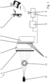
- FIG 1 A system 1 for detecting image parameters during the exposure of films 2, in particular X-ray films, is shown schematically with the reference numeral 1.
- the representation according to figure 1 shows a radiation source 10 from which radiation 4 is emitted in the direction of the examination object 12 and film 2 .
- the radiation 4 from the radiation source 10 penetrates the examination object 12 , with part of the radiation 4 being absorbed by the examination object 12 .
- the contour and also the inner structure of the examination object 12 can be recognized on the recording. This is the well-known principle of film-based X-ray imaging for non-destructive testing.
- the system according to the invention has a digital detector element 3 which can be attached to the film 2 (e.g. by adhesion or by clamping using suitable holding elements) and which detects the radiation 4 incident on the film 2 during exposure and from this a signal generated, which allows conclusions to be drawn about the image parameters achieved during exposure.
- image parameters include, in particular, the contrast produced on the film 2 by the exposure.
- the detector element 3 is connected to an evaluation system 5 which evaluates the signals from the detector element 3 . In this case, the evaluation system 5 analyzes in particular local exposure differences of the radiation detected with the detector element 3 .
- the evaluation system 5 transmits a message to an operator as soon as the image quality corresponds to the image parameters specified by the operator.
- the evaluation system 5 can also expose the film 2 automatically interrupt as soon as the image quality meets the image parameters desired by the operator.
- a communication unit 6 which transmits the results of the evaluation system 5 to external devices 7 (for example smartphones or laptops) via a wireless connection.
- the evaluation system 5 and possibly also the radiation source 10 can also be controlled remotely via the external devices 7 .
- the detector element 3 is designed as a band that extends in one direction over the entire exposed film area.
- the detector element 3 has a plurality of spatially distributed digital radiation sensors 8, only individual ones being provided with reference symbols for reasons of clarity.
- the radiation sensors 8 are, for example, scintillator crystals with photodetectors assigned to them, or X-ray-sensitive semiconductor elements of a known type, such as are used, for example, in medical X-ray imaging.
- the system 1 has a self-sufficient power supply 9 so that the non-destructive examination of any object (eg building or machine parts) is flexibly possible on site.
- the detector element 3, the evaluation system 5 and the communication unit 6 should be as small and compact as possible. These components then only need a very low power requirement with low voltages ( ⁇ 50V).
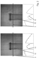
- the figure 2 shows an example of two images (left and right) for which the image parameters are set using the system 1 ( 1 ) are recorded.
- the strip-shaped detector element 3 is arranged in the center of the image for capturing an image line, as indicated by the black line in the recordings.
- a signal is generated which is visualized by the line profile 13 shown under the recordings.
- the data obtained by the detector element 3 is considered as a line profile signal 13 from the image for examining local differences.
- the ones with the system 1 ( Fig.1 ) monitored recordings show a digital x-ray of a plastic pipe.
- the strip-shaped detector element 3 provided (one-dimensional) spatially resolved exposure information.
- the original digital radiograph On the left of the figure 2 is the original digital radiograph with associated line profile 13 shown below.
- a subsampled version of the digital image is shown at 2% of the original image size.
- a correspondingly recorded line profile 13 is located below this recording.
- the radiation 4 ( 1 ) is more strongly absorbed in the area of the examination object 12, so that locally less incident radiation is measured by the detector element 3.
- Various indicators can be taken into account in order to use the signals detected by the detector element 3 to quantify whether the image quality corresponds to the specifications. Possible indicators result from the gradient and the curvature of the line profile 13.
- the evaluation system 5 ( 1 ) Based on these two indicators, the evaluation system 5 ( 1 ) a decision can be made as to whether there are sufficient intensity changes in the signal detected along the band, from which the image contrast can be inferred.
- the line profile 13 can be automatically segmented in order to determine different segments that are to be assigned to the image content of interest or to the background. For example, by applying the known CUSUM test to the data series given by the line profile 13, abrupt intensity changes in the image can be identified. This allows the image quality to be quantified. This evaluation enables the evaluation system 5 ( 1 ), to generate a message or to automatically interrupt the exposure as soon as the image quality meets specified target values.
Landscapes
- Physics & Mathematics (AREA)
- Health & Medical Sciences (AREA)
- Life Sciences & Earth Sciences (AREA)
- General Physics & Mathematics (AREA)
- High Energy & Nuclear Physics (AREA)
- Molecular Biology (AREA)
- Spectroscopy & Molecular Physics (AREA)
- Measurement Of Radiation (AREA)
- Apparatus For Radiation Diagnosis (AREA)
- Analysing Materials By The Use Of Radiation (AREA)
Description
- Die Erfindung betrifft ein System zur Erfassung von Bildparametern bei der Belichtung von Filmen, insbesondere Röntgenfilmen.
- Derartige Röntgenfilme werden häufig im Bereich der zerstörungsfreien Prüfung (NDT = non-destructive testing) eingesetzt. Die zerstörungsfreie Prüfung ist eine Disziplin, die nicht-invasive Techniken verwendet, um den Zustand von Materialien und Strukturen zu untersuchen. Die Hauptaufgabe der zerstörungsfreien Prüfung ist es, Fehler oder Defekte aufzudecken und Anhaltspunkte zu geben, ob der Fehler oder Defekt hinsichtlich der Betriebssicherheit und / oder der Zuverlässigkeit des untersuchten Objektes wesentlich ist.
- Zur zerstörungsfreien Prüfung werden viele verschiedene Technologien und Methoden angewandt. Eine der am häufigsten verwendeten Technologien für die volumetrische Prüfung ist die Radiographie. Hier werden insbesondere Röntgenstrahlen oder Gammastrahlen verwendet, um ein radiographisches Bild des zu prüfenden Objektes zu erzeugen. Die eindringende Strahlung wird verwendet, um die interne Struktur von festen und harten Materialien, wie etwa Stahl oder anderen Metallen oder auch Beton, zu visualisieren. Bei dem übliche Prüfungsverfahren befindet sich auf der einen Seite des Untersuchungsobjekts eine Strahlungsquelle (Gamma-/Röntgenstrahlung) und auf der anderen Seite des Untersuchungsobjekts ein strahlungsempfindlicher Film, um die das Untersuchungsobjekt durchdringende Strahlung zu detektieren. Dies ermöglicht die Visualisierung des Untersuchungsobjekts in Bezug auf Unterschiede hinsichtlich der Dicke, Änderungen in der Struktur oder andere innerer Defekte oder Fehler.
- Bei der filmbasierten Radiographie unter Verwendung von Gamma-Radioisotopen wie Co-60 oder Cs-137 werden Bilder durch eine chemische Wechselwirkung der Photonen mit dem Filmmaterial erzeugt. Der Film besteht hierzu aus einer Gelatine-Emulsion die strahlungsempfindliche Silberhalogenidkristalle enthält und eine flexible, transparente, blau getönte Basis. Wenn die energetischen Photonen auf die strahlungsempfindlichen Silberhalogenidkristalle auftreffen, geschieht eine chemische Wechselwirkung im Inneren des Filmmaterials was zur Belichtung des Filmes führt.
- Da die chemischen Substanzen in Röntgenfilmen strahlungsempfindlich sind, kann es leicht zu einer Überbelichtung des Films kommen, was die Qualität des endgültigen Bildes verschlechtert. Diese Überbelichtung kann dazu führen, dass der Film zu dunkel wird und das aufgenommene Bild unbrauchbar ist. Eine Unterbelichtung des Films, auf der anderen Seite, kann ebenfalls zu einem unbrauchbaren Bild führen, da die gewünschten Einzelheiten des Untersuchungsobjekts auf dem Bild nicht zu sehen sind. Um ausreichend detaillierte Informationen von dem Untersuchungsobjekt zu gewinnen, ist es erforderlich, dass die Belichtung des Films nach einer angemessenen Zeit (Belichtungszeit) beendet wird. Die korrekte Belichtungszeit hängt von dem Untersuchungsobjekt und der verwendeten Strahlungsquelle ab und ist in der Praxis häufig schwierig zu bestimmen.
- Die Qualität eines Röntgenbildes und damit die Erkennbarkeit von Defekten und Fehlern des Untersuchungsobjektes hängen hauptsächlich vom Kontrast, der Schärfe und der Körnigkeit des Bildes ab. Dies sind die grundlegenden Bildparameter, welche die Qualität eines Röntgenbildes bestimmen. Diese Parameter haben einen großen Einfluss auf die Nachweisbarkeit von Defekten und Fehlern in einem Untersuchungsobjekt. Während die Schärfe und die Körnigkeit hauptsächlich vom Versuchsaufbau und der Qualität des Films abhängen, hängt der Kontrast stark von der Strahlungsenergie und der Dauer der Belichtung ab. Die erforderliche Strahlungsenergie und nötige Belichtungsdauer hängen von weiteren Faktoren ab, welche die Bildqualität und damit die Nachweisbarkeit von Defekten und Fehlern beeinflussen können.
- Heute ist das Verfahren für die zerstörungsfreie Prüfung anhand von Röntgenaufnahmen unter Verwendung einer Gammaquelle und eines fotografischen Films abhängig von der Anordnung der Strahlungsquelle und dem Film sowie der Belichtungszeit, wobei der Bediener während der Belichtung einen Sicherheitsabstand zu dem Untersuchungsobjekt und der Prüfungsvorrichtung einhalten muss.
- Diese Prüfungen laufen teilweise über einen langen Zeitraum, geschuldet durch teilweise sehr große Objekte und damit einer entsprechend geringen Anzahl von Gammaphotonen, die vom Film aufgenommen werden. Die bekannten Verfahren nutzen sehr oft nuklidbasierte Strahlungsquellen und analoge Filme.
- Erst nach der Belichtung kann der Bediener den belichteten Film verarbeiten (entwickeln und digitalisieren), um die Bildanalyse vorzunehmen und Defekte und Fehler des Untersuchungsobjektes zu finden. Erst zu diesem Zeitpunkt kann derzeit festgestellt werden, ob sich das gewonnene Bildmaterial für die Analyse zur zerstörungsfreien Prüfung eignet oder ob eine erneute Aufnahme mit veränderten Parametern erforderlich ist.
- Die
EP 0779 521 A1 betrifft ein System zur Erfassung von Röntgenstrahlung, wobei das System Detektorelemente aufweist, wobei die Detektorelemente dazu ausgebildet, sind auftreffende Strahlung oder transmittierte Strahlung zu detektieren, und wobei das Detektorelement dazu ausgebildet ist, dabei ein Signal zu erzeugen, aus dem Parameter ableitbar sind. - Die
WO 2007/034003 A1 beschreibt ein System zur Erfassung von Bildparametern bei der Belichtung von Röntgenfilmen, wobei das System ein Detektorelement aufweist, wobei das Detektorelement dazu ausgebildet ist, die bei der Belichtung durch den Film transmittierte Strahlung ortsaufgelöst zu detektieren, und wobei das Detektorelement dazu ausgebildet ist, dabei ein Signal zu erzeugen, um die Strahlungsdosis abhängig von dem verwendeten Film zu steuern. - In der
EP 0 849 980 A1 wird über ein Fotobilddetektor ein elektrisches Bildsignal erzeugt. - In KUO TSUNG-TER ET AL : "Flexible x-ray imaging detector based on direct conversion in amorphous selenium", JOURNAL OF VACUUM SCIENCE AND TECHNOLOGY: PART A, AVS /AIP, MELVILLE, NY., US, Bd. 32, Nr. 4, 12. Juni 2014 (2014-06-12) ist ein flexibler Röntgendetektor beschrieben, mit dem die Verwendung von konventionellen Röntgenfilmen ersetzt werden kann.
- Der Erfindung stellt sich somit weiterhin das Problem, ein System anzugeben, welches die beschriebenen Nachteile behebt und eine einfache und schnelle Herstellung optimal belichteter Aufnahmen ermöglicht und eine Vorhersagemöglichkeit für den optimalen Belichtungszeitpunkt zulässt.
- Erfindungsgemäß wird dieses Problem durch eine Einheit aus Film und System zur Erfassung der Bildparameter bei der Belichtung des Films mit den Merkmalen des Patentanspruchs 1 gelöst.
- Erfindungsgemäß umfasst das System zur Erfassung von Bildparametern bei der Belichtung von Filmen, insbesondere Röntgenfilmen, ein Detektorelement, das an einem strahlungssensitiven Film lösbar anbringbar ist (z.B. an der von der verwendeten Strahlungsquelle abgewandten Rückseite des Films oder an der Vor- oder Rückseite einer den Film aufnehmenden Kassette) und das die bei der Belichtung auf den Film auftreffende Strahlung oder die durch den Film transmittierte Strahlung ortsaufgelöst detektiert und dabei ein Signal erzeugt, aus dem durch die laufende Belichtung erzeugte Bildparameter ableitbar sind. Aufgrund der hohen Bedeutung der Belichtungszeit und deren Einfluss auf die Bildqualität ist die erfindungsgemäße Echtzeitüberwachung der erzeugten Bildparameter während der laufenden Belichtung von großem Vorteil. Hierdurch lassen sich nicht nur die Kosten reduzieren, indem fehlerhaft belichtete Filme vermieden werden, sondern es lässt sich auch die Zeit der Bauteilüberprüfung reduzieren, da keine Wiederholungen der Aufnahmen erforderlich sind.
- Das hier vorgeschlagene System bezieht sich insbesondere auf die röntgenologische zerstörungsfreie Prüfung und insbesondere auf die Verwendung von Röntgenfilmen. Hier besteht besonders die Notwendigkeit der Echtzeitüberwachung der Bildqualität, insbesondere des Bildkontrastes. Die Grundidee der vorgeschlagenen Lösung besteht darin, an einem einfachen Film das (möglichst digitale) Detektorelement anzubringen und hierdurch eine Echtzeit-Monitoring-Lösung zu schaffen. Mit einem solchen System zur Echtzeit-Digital-Datenerfassung und -verarbeitung kann automatisch detektiert werden, wann die Bildqualität im Film, insbesondere der Kontrast, optimal ist. Somit kann die Belichtung automatisch zu genau dem richtigen Zeitpunkt beendet werden.
- Die lösbare Anbringbarkeit des Detektorelementes an dem Film ermöglicht es, das Detektorelement für eine Vielzahl von Aufnahmen mit jeweils neuem Filmmaterial immer wieder zu verwenden. Die Anbringung an dem Film sorgt für eine Fixierung an dem Film während der Belichtung.
- Vorteilhafte Ausgestaltungen und Weiterbildungen der Erfindung ergeben sich aus den abhängigen Ansprüchen.
- Gemäß einer vorteilhaften Ausgestaltung der Erfindung ist vorgesehen, dass aus dem von dem Detektorelement erzeugten Signal der durch die laufende Belichtung auf dem Film erzeugte Bildkontrast ableitbar ist. Durch den Erhalt von Echtzeit-Informationen zu dem aktuell erreichten Bildkontrast kann die Belichtung so gesteuert werden, dass optimale Ergebnisse bei den Aufnahmen erzielt werden.
- Eine vorteilhafte Ausführung ist, dass das Detektorelement mit einem Auswertungssystem verbunden ist. Das mit dem Detektorelement verbundene Auswertungssystem führt die Ableitung der Bildparameter aus den Messsignalen durch und ermöglicht die darauf basierende Überwachung der Belichtung.
- Eine bevorzugte Ausführung sieht vor, dass das Auswertungssystem lokale Belichtungsunterschiede anhand der Signale des Detektorelementes analysiert. Anhand der lokalen Belichtungsunterschiede lässt sich die Qualität der Aufnahme während der Belichtung bewerten.
- Besonders vorteilhaft ist die Weiterbildung, dass das Auswertungssystem eine Meldung erzeugt, sobald absehbar ist, dass die Bildqualität vorgebbaren Kriterien entspricht. Die unmittelbare Rückmeldung des Auswertungssystems ermöglicht diesem zur Erreichung einer optimalen Bildqualität rechtzeitig einzugreifen, z.B. um die Belichtung zu beenden. Dem Benutzer vor Ort muss es möglich sein, die Belichtung abzubrechen oder zu beenden. Dies kann geschehen durch die komplette Strahlenabschirmung der Strahlungsquelle, so dass keine weiteren Gammaphotonen mehr am Detektorelement ankommen. Es könnte allerdings auch ein Bleielement mechanisch oder elektrisch über den Film gezogen werden.
- Weiter vorteilhaft ist die Ausgestaltung, dass das Auswertungssystem die Belichtung des Filmes automatisch unterbricht, sobald die Bildqualität vorgebbaren Kriterien entspricht. Die automatische Unterbrechung der Aufnahme bei Erreichung von vorgegebenen Parametern (z.B. hinsichtlich Kontrast oder Gesamtdosis) erleichtert die Erstellung von Aufnahmen und reduziert die erforderliche Erfahrung des Bedienpersonals.
- Eine weitere vorteilhafte Ausführungsform der Erfindung sieht vor, dass das Auswertungssystem mit einer Kommunikationseinheit verbunden ist, welche Ergebnisse des Auswertungssystems an externe Geräte übermittelt. Die vorzugsweise drahtlose Verbindung des Auswertungssystems mit einem externen Gerät erleichtert die Bedienung des Systems. Auf diese Weise kann das Auswertungssystem auch mit einem ausreichenden Sicherheitsabstand über ein externes Gerät ausgelesen oder bedient werden.
- Gemäß einer vorteilhaften Ausgestaltung der Erfindung ist vorgesehen, dass das Detektorelement eine Mehrzahl von digitalen Strahlungssensoren, z.B. in einer Array-Anordnung, umfasst. Die digitale Ausgestaltung des Detektorelements ermöglicht die elektronische Auswertung und Weiterverarbeitung der Messsignale in Echtzeit. Die Kosten der digitalen Sensorik sind nicht sehr relevant, da das Detektorelement beliebig oft verwendet werden kann. Die Mehrkosten werden durch die Einsparungen resultierend aus dem Nutzen des erfindungsgemäßen Systems (Vermeidung von Fehlbelichtungen) überkompensiert.
- Erfindungsgemäß ist das Detektorelement als längliches Band ausgebildet. Die bandförmige Ausbildung des Detektorelements bietet die Möglichkeit, einen schmalen, streifenförmigen Ausschnitt der Filmbelichtung zu erfassen. Ein eindimensionales Array von digitalen Strahlungssensoren kann vorteilhaft an dem Band angeordnet sein. Die Aufnahme eines somit gleichsam eindimensionalen digitalen Bildes während der Filmbelichtung reicht aus, um die Bildqualität (insbesondere hinsichtlich des erzielten Kontrastes) zu beurteilen.
- Weiterhin erstreckt sich das Band erfindungsgemäß entlang seiner Längserstreckung über den gesamten Film. Die Erstreckung des Detektorelementes über den gesamten belichteten Bereich des Films in einer Richtung macht eine hinreichende Erfassung der Bildparameter bei der Belichtung möglich. Das Band wird bei der Aufnahme möglichst so an dem Film angeordnet, dass die Intensitätsschwankungen entlang des Bandverlaufes maximal sind. Dies ermöglicht die zuverlässige Beurteilung der Bildqualität anhand des von dem bandförmigen Detektorelement gelieferten eindimensionalen Digitalbildes.
- Außerdem ist das Band erfindungsgemäß flexibel ausgestaltet. Die flexible Ausgestaltung des Detektorelementes macht die Handhabung, z.B. die Anbringung des Bandes an dem Film besonders einfach. Außerdem kann das flexible Band platzsparend verstaut werden. Weiter kann das Band genutzt werden, auch wenn der Film bei der Belichtung eine beliebig gekrümmte oder gebogene Form hat.
- Vorzugsweise weist das System eine Stromversorgung auf. Hier ist es von besonderem Vorteil, wenn die Stromversorgung durch einen Akkumulator autark ist, sodass das System unabhängig von den lokalen Gegebenheiten am Untersuchungsobjekt eingesetzt werden kann.
- Weitere Merkmale, Einzelheiten und Vorteile der Erfindung ergeben sich aufgrund der nachfolgenden Beschreibung sowie anhand der Zeichnungen. Ausführungsbeispiele der Erfindung sind in den folgenden Zeichnungen rein schematisch dargestellt und werden nachfolgend näher beschrieben. Einander entsprechende Gegenstände oder Elemente sind in allen Figuren mit den gleichen Bezugszeichen versehen. Es zeigen:
- Figur 1
- schematische Darstellung des erfindungsgemäßen Systems;
- Figur 2
- Röntgenbilder mit Profillinien.
- In
Figur 1 mit dem Bezugszeichen 1 bezeichnet ist ein System 1 zur Erfassung von Bildparametern bei der Belichtung von Filmen 2, insbesondere Röntgenfilmen, schematisch dargestellt. Die Darstellung gemäßFigur 1 zeigt eine Strahlungsquelle 10, von der aus Strahlung 4 in Richtung Untersuchungsobjekt 12 und Film 2 emittiert wird. Bei der Belichtung des Films 2 durchdringt die Strahlung 4 der Strahlungsquelle 10 das Untersuchungsobjekt 12, wobei ein Teil der Strahlung 4 durch das Untersuchungsobjekt 12 absorbiert wird. Hierdurch ist nach ausreichender Belichtung des Films 2 die Kontur und auch die innere Struktur des Untersuchungsobjektes 12 auf der Aufnahme zu erkennen. Dies ist das bekannte Prinzip der filmbasierten Röntgenbildgebung zur zerstörungsfreien Prüfung. - Wie oben erwähnt, ist die Belichtung entscheidend für die Erreichung einer optimalen Bildqualität. Aus diesem Grund weist das erfindungsgemäßen System ein digitales Detektorelement 3 auf, das an dem Film 2 angebracht werden kann (z.B. durch Adhäsion oder durch Anklemmen mittels geeigneter Halteelemente) und das die bei der Belichtung auf den Film 2 auftreffende Strahlung 4 detektiert und hieraus ein Signal erzeugt, welches auf die bei der Belichtung erreichten Bildparameter zurückschließen lässt. Diese Bildparameter umfassen insbesondere den durch die Belichtung erzeugten Kontrast auf dem Film 2. Das Detektorelement 3 ist mit einem Auswertungssystem 5 verbunden, welches die Signale des Detektorelementes 3 auswertet. Das Auswertungssystem 5 analysiert hierbei insbesondere lokale Belichtungsunterschiede der mit dem Detektorelement 3 erfassten Strahlung. Anhand dieser Auswertungen übermittelt das Auswertungssystem 5 eine Meldung an einen Bediener, sobald die Bildqualität den vom Bediener vorgegebenen Bildparametern entspricht. Das Auswertungssystem 5 kann zudem die Belichtung des Films 2 automatisch unterbrechen, sobald die Bildqualität den vom Bediener gewünschten Bildparametern entspricht. An das Auswertungssystem 5 angeschlossen ist außerdem eine Kommunikationseinheit 6, welche über eine drahtlose Verbindung die Ergebnisse des Auswertungssystems 5 an externe Geräte 7 (beispielsweise Smartphones oder Laptops) übermittelt. Über die externen Geräte 7 kann das Auswertungssystem 5 und ggf. auch die Strahlungsquelle 10 zudem aus der Ferne gesteuert werden.
- In
Figur 1 gut zu erkennen ist, dass das Detektorelement 3 als Band ausgebildet ist, das sich in einer Richtung über den gesamten belichteten Filmbereich erstreckt. Das Detektorelement 3 weist eine Mehrzahl von räumlich verteilten digitalen Strahlungssensoren 8 auf, wobei aus Gründen der Übersicht nur einzelne mit Bezugszeichen versehen sind. Die Strahlungssensoren 8 sind z.B. Szintillatorkristalle mit diesen jeweils zugeordneten Photodetektoren oder röntgenempflindliche Halbleiterelemente an sich bekannter Art, wie sie z.B. in der medizinischen Röntgenbildgebung Verwendung finden. Das System 1 verfügt über eine autarke Stromversorgung 9, damit die zerstörungsfreie Untersuchung von beliebigen Objekten (z.B. Bauwerks- oder Maschinenteilen) vor Ort flexibel möglich ist. Für die optimale Anbringung an dem Film ist das Detektorelement 3, die Auswertungssystem 5 und die Kommunikationseinheit 6 möglichst klein und kompakt auszuführen. Diese Komponenten benötigen dann nur einen sehr geringem Strombedarf mit niedrigen Spannungen (< 50V). - Die
Figur 2 zeigt beispielhaft zwei Bildaufnahmen (links und rechts) zu denen die Bildparameter mittels des erfindungsgemäßen Systems 1 (Fig. 1 ) erfasst werden. Das bandförmige Detektorelement 3 ist bei diesen Aufnahmen in der Bildmitte zur Erfassung einer Bildzeile angeordnet, wie in den Aufnahmen durch die schwarze Linie angedeutet. Durch die Erfassung der auf den Film 2 (Fig. 1 ) auftreffenden Strahlung 4 (Fig. 1 ) wird ein Signal erzeugt, welches durch das unter den Aufnahmen jeweils dargestellte Linienprofil 13 visualisiert ist. Die durch das Detektorelement 3 erhaltenen Daten werden zur Untersuchung lokaler Unterschiede als ein Linienprofilsignal 13 aus dem Bild betrachtet. Die mit dem System 1 (Fig.1 ) überwachten Aufnahmen zeigen ein digitales Röntgenbild eines Kunststoffrohres. Das bandförmige Detektorelement 3 lieferte(eindimensional) ortsaufgelöste Informationen zur Belichtung. Auf der linken Seite derFigur 2 ist die ursprüngliche digitale Röntgenaufnahme mit zugehörigem Linienprofil 13 unterhalb gezeigt. Auf der rechten Seite derFigur 2 ist eine unterabgetastete Version des digitalen Bildes mit 2% der ursprünglichen Bildgröße gezeigt. Unterhalb dieser Aufnahme befindet sich ein entsprechend erfasstes Linienprofil 13. Wie deutlich an den Linienprofilen 13 zu erkennen ist, wird die Strahlung 4 (Fig. 1 ) im Bereich des Untersuchungsobjektes 12 stärker absorbiert, sodass lokal weniger auftreffende Strahlung durch das Detektorelement 3 gemessen wird. Um anhand der vom Detektorelement 3 erfassten Signale zu quantifizieren, ob die Bildqualität den Vorgaben entspricht, können verschiedene Indikatoren berücksichtigt werden. Mögliche Indikatoren ergeben sich aus der Steigung und der Krümmung des Linienprofils 13. Anhand dieser beiden Indikatoren kann durch das Auswertungssystem 5 (Fig. 1 ) entschieden werden, ob hinreichend Intensitätsänderungen des entlang des Bandes erfassten Signals vorliegen, woraus auf den Bildkontrast geschlossen werden kann. Außerdem kann das Linienprofil 13 automatisch segmentiert werden, um verschiedene Segmente zu ermitteln, die den interessierenden Bildinhalten bzw. dem Hintergrund zuzuordnen sind. Z.B. durch Anwendung des bekannten CUSUM-Tests auf die durch das Linienprofil 13 gegebene Datenreihe können abrupte Intensitätsänderungen im Bild identifiziert werden. Hierdurch lässt sich die Bildqualität quantifizieren. Diese Auswertung ermöglicht es dem Auswertungssystem 5 (Fig. 1 ), eine Meldung zu erzeugen oder die Belichtung automatisch zu unterbrechen, sobald die Bildqualität vorgegebenen Zielwerten entspricht. - Der Vergleich der beiden unterschiedlich ortsaufgelösten Linienprofile 13 zeigt, dass für das Detektorelement 3 ein Sensorarray niedriger Auflösung (um ein mehrfaches niedriger als die Auflösung der Filmaufnahme), d.h. mit nur wenigen diskreten Sensorelementen 8 ausreicht, um die Bildqualität hinreichend zuverlässig zu beurteilen.
- Mit dem hier beschriebenen System ist eine Vorhersagemöglichkeit gegeben, um basierend auf dem Fortschritt der Belichtung zum aktuellen Zeitpunkt in einem Vergleich die Belichtung zu einem späteren Zeitpunkt vorherzusagen. Hierdurch ist ableitbar, wann die Belichtung nicht nur gut und ausreichend, sondern optimal ist.
-
- 1
- System
- 2
- Film
- 3
- Detektorelement
- 4
- Strahlung
- 5
- Auswertungssystem
- 6
- Kommunikationseinheit
- 7
- externes Gerät
- 8
- Strahlungssensoren
- 9
- Stromversorgung
- 10
- Strahlungsquelle
- 11
- Bediener
- 12
- Untersuchungsobjekt
- 13
- Profillinie
Claims (9)
- Einheit aus a) einem Film (2), insbesondere Röntgenfilm, und b) einem System (1) zur Erfassung von Bildparametern bei der Belichtung des Films (2), wobei das System (1) ein Detektorelement (3) aufweist, wobei das Detektorelement (3) dazu ausgebildet ist, die bei einer Belichtung auf den Film (2) auftreffende Strahlung (4) oder die durch den Film transmittierte Strahlung (4) ortsaufgelöst zu detektieren,
wobei
das Detektorelement (3) an dem Film (2) lösbar angebracht ist und als längliches Band ausgebildet ist, wobei sich das Band entlang des Films erstreckt und flexibel ist, und wobei das Detektorelement (3) dazu ausgebildet ist ein Signal zu erzeugen, aus dem durch die laufende Filmbelichtung erzeugte Bildparameter ableitbar sind. - Einheit nach Anspruch 1, dadurch gekennzeichnet, dass das Detektorelement (3) dazu ausgebildet ist, ein Signal zu erzeugen aus dem der durch die laufende Belichtung auf dem Film (2) erzeugte Bildkontrast ableitbar ist.
- Einheit nach Anspruch 1 oder 2, gekennzeichnet durch ein Auswertungssystem (5), wobei das Detektorelement (3) mit dem Auswertungssystem (5) verbunden ist.
- Einheit nach Anspruch 3, dadurch gekennzeichnet, dass das Auswertungssystem (5) lokale Belichtungsunterschiede analysiert.
- Einheit nach Anspruch 3 oder 4, dadurch gekennzeichnet, dass das Auswertungssystem (5) eine Meldung erzeugt, sobald die Bildqualität vorgebbaren Kriterien entspricht.
- Einheit nach einem der Ansprüche 3 bis 5, dadurch gekennzeichnet, dass das Auswertungssystem (5) dazu ausgebildet ist, die Belichtung des Filmes (2) automatisch zu unterbrechen, sobald die Bildqualität vorgebbaren Kriterien entspricht.
- Einheit nach einem der Ansprüche 3 bis 6, dadurch gekennzeichnet, dass das Auswertungssystem (5) mit einer Kommunikationseinheit (6) verbunden ist, welche dazu ausgebildet ist, Ergebnisse des Auswertungssystems (5) an externe Geräte (7) zu übermitteln.
- Einheit nach einem der Ansprüche 1 bis 7, dadurch gekennzeichnet, dass das Detektorelement (3) eine Mehrzahl von digitalen Strahlungssensoren umfasst.
- Verfahren zum Vorbereiten des Belichtens eines Films (2), insbesondere Röntgenfilms, wobei das Verfahren umfasst:Bereitstellen eines Systems (1) zur Erfassung von Bildparametern bei der Belichtung des Films (2), wobei das System (1) ein Detektorelement (3) aufweist, wobei das Detektorelement (3) als längliches und flexibles Band ausgebildet ist und dazu ausgebildet ist, die bei einer Belichtung auf den Film (2) auftreffende Strahlung (4) oder die durch den Film transmittierte Strahlung (4) ortsaufgelöst zu detektieren, und wobei das Detektorelement (3) dazu ausgebildet ist ein Signal zu erzeugen, aus dem durch die laufende Filmbelichtung erzeugte Bildparameter ableitbar sind;Anbringen des Detektorelements (3) an dem Film (2) derart, dass sich das Band entlang des Films erstreckt und wieder von dem Film lösbar ist.
Applications Claiming Priority (2)
| Application Number | Priority Date | Filing Date | Title |
|---|---|---|---|
| DE102016123846.5A DE102016123846A1 (de) | 2016-12-08 | 2016-12-08 | Detektorband für Röntgenfilm |
| PCT/EP2017/081954 WO2018104497A1 (de) | 2016-12-08 | 2017-12-08 | Detektorband für röntgenfilm |
Publications (2)
| Publication Number | Publication Date |
|---|---|
| EP3552460A1 EP3552460A1 (de) | 2019-10-16 |
| EP3552460B1 true EP3552460B1 (de) | 2023-03-15 |
Family
ID=61148162
Family Applications (1)
| Application Number | Title | Priority Date | Filing Date |
|---|---|---|---|
| EP17837947.5A Active EP3552460B1 (de) | 2016-12-08 | 2017-12-08 | Detektorband für röntgenfilm |
Country Status (5)
| Country | Link |
|---|---|
| US (1) | US11086027B2 (de) |
| EP (1) | EP3552460B1 (de) |
| CN (1) | CN110192435B (de) |
| DE (1) | DE102016123846A1 (de) |
| WO (1) | WO2018104497A1 (de) |
Families Citing this family (2)
| Publication number | Priority date | Publication date | Assignee | Title |
|---|---|---|---|---|
| DE102016123846A1 (de) | 2016-12-08 | 2018-06-14 | Visus Health It Gmbh | Detektorband für Röntgenfilm |
| FR3161953A1 (fr) * | 2024-05-06 | 2025-11-07 | Institut De Soudure | Surveillance de la densité optique d’une image au cours d’un contrôle radiographique |
Family Cites Families (36)
| Publication number | Priority date | Publication date | Assignee | Title |
|---|---|---|---|---|
| DE2045640C3 (de) * | 1970-09-16 | 1975-01-16 | Siemens Ag, 1000 Berlin Und 8000 Muenchen | Einrichtung zur Kennzeichnung von Röntgenaufnahmen |
| US3932756A (en) * | 1974-06-24 | 1976-01-13 | Sybron Corporation | X-ray detector for a panoramic X-ray device |
| US4053774A (en) * | 1975-08-08 | 1977-10-11 | California Institute Of Technology | X-ray exposure sensor and controller |
| DE2646638C2 (de) * | 1976-10-15 | 1986-08-14 | Siemens AG, 1000 Berlin und 8000 München | Zahnärztliche Röntgendiagnostikeinrichtung |
| JPS554817A (en) * | 1978-06-27 | 1980-01-14 | Toshiba Corp | X-ray automatic exposure controller |
| DE3008261C2 (de) * | 1980-03-04 | 1988-05-05 | Siemens AG, 1000 Berlin und 8000 München | Röntgendiagnostikeinrichtung mit Mitteln zur Bildung eines Transparenzsignals |
| DE3143157A1 (de) * | 1981-10-30 | 1983-05-11 | Siemens AG, 1000 Berlin und 8000 München | Zahnaerztliche roentgendiagnostikeinrichtung |
| US4454606A (en) * | 1983-05-23 | 1984-06-12 | General Electric Company | Reconfigurable x-ray AEC compensation |
| NL8501795A (nl) * | 1985-06-21 | 1987-01-16 | Optische Ind De Oude Delft Nv | Inrichting en werkwijze voor spleetradiografie met verschillende roentgenstralingsenergieen. |
| NL8701122A (nl) * | 1987-05-12 | 1988-12-01 | Optische Ind De Oude Delft Nv | Inrichting voor spleetradiografie met beeldharmonisatie. |
| GB8815179D0 (en) * | 1988-06-25 | 1988-08-03 | Racal Safety Ltd | Differential pressure sensor |
| US5966425A (en) * | 1989-12-07 | 1999-10-12 | Electromed International | Apparatus and method for automatic X-ray control |
| US5585638A (en) * | 1995-12-14 | 1996-12-17 | General Electric Company | X-ray detector for automatic exposure control of an imaging apparatus |
| US6207958B1 (en) * | 1996-02-12 | 2001-03-27 | The University Of Akron | Multimedia detectors for medical imaging |
| US5694449A (en) * | 1996-05-20 | 1997-12-02 | General Electric Company | Method and system for detecting and correcting erroneous exposures generated during x-ray imaging |
| JPH10155779A (ja) * | 1996-12-04 | 1998-06-16 | Ritsuku:Kk | X線撮影装置および出力写真 |
| US5751783A (en) | 1996-12-20 | 1998-05-12 | General Electric Company | Detector for automatic exposure control on an x-ray imaging system |
| JP3836208B2 (ja) * | 1997-04-09 | 2006-10-25 | 浜松ホトニクス株式会社 | 医療用小型x線画像検出装置 |
| JP2000035623A (ja) * | 1998-07-16 | 2000-02-02 | Noritsu Koki Co Ltd | 露光装置 |
| JP4140670B2 (ja) * | 1998-11-09 | 2008-08-27 | Hoya株式会社 | 画像読取装置 |
| US6243441B1 (en) * | 1999-07-13 | 2001-06-05 | Edge Medical Devices | Active matrix detector for X-ray imaging |
| JP2003505705A (ja) * | 1999-07-26 | 2003-02-12 | エッジ メディカル デバイシス リミティド | X線画像化用ディジタル検出器 |
| US6394650B1 (en) * | 1999-10-27 | 2002-05-28 | Konica Corporation | Photographic combination for use in radiography |
| US6728333B2 (en) * | 2001-04-18 | 2004-04-27 | William Beaumont Hospital | Film density template and method for comparison of film exposure |
| FI113897B (fi) * | 2001-11-23 | 2004-06-30 | Planmed Oy | Automaattivalotusmenetelmä ja automaattivalotusjärjestelmä |
| US20050053199A1 (en) * | 2003-09-04 | 2005-03-10 | Miles Dale A. | Portable x-ray device and method |
| DE102005022899A1 (de) * | 2005-05-18 | 2006-11-23 | Siemens Ag | Verfahren und Einrichtung zum Erzeugen eines digitalen tomosynthetischen 3D-Röntgenbildes von einem Untersuchungsobjekt |
| DE102005036514B4 (de) * | 2005-08-03 | 2017-08-31 | Siemens Healthcare Gmbh | Verfahren und Einrichtung zum Erzeugen eines digitalen Röntgenbildes von einem Untersuchungsobjekt |
| FI119968B (fi) | 2005-09-15 | 2009-05-29 | Planmed Oy | Automaattivalotusmenetelmä ja -järjestelmä |
| CA2732996A1 (en) * | 2008-08-07 | 2010-05-14 | University Of Massachusetts | Spectroscopic sensors |
| DE112009005291B4 (de) * | 2009-09-28 | 2025-02-27 | Iray Technology Company Limited | Röntgenstrahlen-Bilddetektorvorrichtung |
| JP5979839B2 (ja) * | 2011-09-27 | 2016-08-31 | キヤノン株式会社 | X線画像撮影装置 |
| IN2014CN03975A (de) * | 2011-11-07 | 2015-09-04 | Koninkl Philips Nv | |
| JP2014018424A (ja) * | 2012-07-18 | 2014-02-03 | Canon Inc | 放射線画像処理装置、画像処理方法、及びプログラム |
| JP6684929B2 (ja) * | 2016-05-20 | 2020-04-22 | コーニンクレッカ フィリップス エヌ ヴェKoninklijke Philips N.V. | 血管内圧力測定及び外部超音波撮像を使用して脈波伝播速度を決定するための関連するデバイス、システム、及び方法 |
| DE102016123846A1 (de) | 2016-12-08 | 2018-06-14 | Visus Health It Gmbh | Detektorband für Röntgenfilm |
-
2016
- 2016-12-08 DE DE102016123846.5A patent/DE102016123846A1/de not_active Ceased
-
2017
- 2017-12-08 EP EP17837947.5A patent/EP3552460B1/de active Active
- 2017-12-08 WO PCT/EP2017/081954 patent/WO2018104497A1/de not_active Ceased
- 2017-12-08 CN CN201780083816.7A patent/CN110192435B/zh active Active
- 2017-12-08 US US16/467,995 patent/US11086027B2/en active Active
Also Published As
| Publication number | Publication date |
|---|---|
| EP3552460A1 (de) | 2019-10-16 |
| CN110192435A (zh) | 2019-08-30 |
| DE102016123846A1 (de) | 2018-06-14 |
| US11086027B2 (en) | 2021-08-10 |
| WO2018104497A1 (de) | 2018-06-14 |
| CN110192435B (zh) | 2023-05-30 |
| US20190302277A1 (en) | 2019-10-03 |
Similar Documents
| Publication | Publication Date | Title |
|---|---|---|
| DE102011076781B4 (de) | Verfahren zur Korrektur einer Zählratendrift bei einem quantenzählenden Detektor, Röntgen-System mit quantenzählendem Detektor und Schaltungsanordnung für einen quantenzählenden Detektor | |
| EP1489969B1 (de) | Computertomograph mit energiediskriminierenden detektoren | |
| DE102011004598B4 (de) | Verfahren und Computersystem zur Streustrahlkorrektur in einem Multi-Source-CT | |
| DE102015112441A1 (de) | Röntgendurchstrahlungs-Prüfvorrichtung und Fremdstoff-Nachweisverfahren | |
| DE102009013306A1 (de) | Integriertes System und integrierendes Verfahren zur Detektion von radioaktivem Material und Röntgenstrahlungsbildgebung | |
| DE102015217421B4 (de) | Spektrale Filterung von Röntgenstrahlung für energieselektive Röntgenbildgebung | |
| DE60111124T2 (de) | Kollimatorvorrichtung, Röntgeneinrichtung, Testausrüstung, Verfahren zur Prüfung einer Röntgeneinrichtung, Computerprogramm zur Ausführung dieses Verfahrens und Speichermedium lesbar von einem Lesegerät für diesen Computerprogramm | |
| DE102019135722A1 (de) | Röntgenprüfgerät und röntgenprüfverfahren | |
| EP3552460B1 (de) | Detektorband für röntgenfilm | |
| DE2818610A1 (de) | Tomographie-geraet | |
| DE102005022544A1 (de) | Verfahren und Einrichtung zum Aufnehmen eines digitalen Röntgenbildes | |
| DE102004053009A1 (de) | Verfahren zur Abbildung eines Aufnahmeobjektes, insbesondere einer Patientenbrust, mittels eines Röngtengerätes bzw. Röngtengerät zur Abbildung des Aufnahmeobjektes | |
| DE102012210638A1 (de) | Verfahren zur Ermittlung des Zustands einer Strahlungsquelle, sowie Röntgenvorrichtung, insbesondere Röntgenangiographievorrichtung, ausgebildet zur Durchführung des Verfahrens | |
| DE112010005764B4 (de) | Strahlungsdetektorkalibrierung unter Verwendung von Spannungseinspeisung | |
| DE102004039681B4 (de) | Tomographiegerät und Verfahren für ein Tomographiegerät | |
| DE10196220B4 (de) | Verfahren für eine Röhrensprühkorrektur | |
| DE102013202864A1 (de) | Vorrichtungen und Verfahren zum automatischen Öffnen und/oder Schließen einer Türe | |
| WO2014044430A1 (de) | Verfahren und vorrichtung zur bestimmung der durch das zu untersuchende objekt verursachten abschwächung der röntgenstrahlung | |
| DE102007045798A1 (de) | Anordnung zur Aufnahme von Röntgenstrahlen- und/oder Gammastrahlen-Streuungsbildern | |
| DE102018221064B4 (de) | Anordnung und Verfahren zum Durchstrahlen eines Objekts mit elektromagnetischer Strahlung | |
| EP0205825B1 (de) | Verfahren und Vorrichtung zur zerstörungsfreien Durchstrahlungsprüfung | |
| EP0959344A1 (de) | Verfahren und Baugruppe zur Durchführung von Durchstrahlungsprüfungen an Werkstoffeinheiten | |
| DE102013206075B4 (de) | Verfahren zur Korrektur einer Signalverteilung sowie Verfahren und Tomographiegerät zur Reduktion von Bildartefakten | |
| DE112018003454B4 (de) | Echtzeit-röntgendosimeter | |
| DE102010034680A1 (de) | Mammographieverfahren und Mammographiegerät |
Legal Events
| Date | Code | Title | Description |
|---|---|---|---|
| STAA | Information on the status of an ep patent application or granted ep patent |
Free format text: STATUS: UNKNOWN |
|
| STAA | Information on the status of an ep patent application or granted ep patent |
Free format text: STATUS: THE INTERNATIONAL PUBLICATION HAS BEEN MADE |
|
| PUAI | Public reference made under article 153(3) epc to a published international application that has entered the european phase |
Free format text: ORIGINAL CODE: 0009012 |
|
| STAA | Information on the status of an ep patent application or granted ep patent |
Free format text: STATUS: REQUEST FOR EXAMINATION WAS MADE |
|
| 17P | Request for examination filed |
Effective date: 20190708 |
|
| AK | Designated contracting states |
Kind code of ref document: A1 Designated state(s): AL AT BE BG CH CY CZ DE DK EE ES FI FR GB GR HR HU IE IS IT LI LT LU LV MC MK MT NL NO PL PT RO RS SE SI SK SM TR |
|
| AX | Request for extension of the european patent |
Extension state: BA ME |
|
| DAV | Request for validation of the european patent (deleted) | ||
| DAX | Request for extension of the european patent (deleted) | ||
| STAA | Information on the status of an ep patent application or granted ep patent |
Free format text: STATUS: EXAMINATION IS IN PROGRESS |
|
| 17Q | First examination report despatched |
Effective date: 20210701 |
|
| REG | Reference to a national code |
Ref country code: DE Ref legal event code: R079 Ref document number: 502017014511 Country of ref document: DE Free format text: PREVIOUS MAIN CLASS: H05G0001380000 Ipc: G01T0001080000 |
|
| RIC1 | Information provided on ipc code assigned before grant |
Ipc: G01T 1/08 20060101AFI20220818BHEP |
|
| GRAP | Despatch of communication of intention to grant a patent |
Free format text: ORIGINAL CODE: EPIDOSNIGR1 |
|
| STAA | Information on the status of an ep patent application or granted ep patent |
Free format text: STATUS: GRANT OF PATENT IS INTENDED |
|
| INTG | Intention to grant announced |
Effective date: 20220928 |
|
| GRAS | Grant fee paid |
Free format text: ORIGINAL CODE: EPIDOSNIGR3 |
|
| GRAA | (expected) grant |
Free format text: ORIGINAL CODE: 0009210 |
|
| STAA | Information on the status of an ep patent application or granted ep patent |
Free format text: STATUS: THE PATENT HAS BEEN GRANTED |
|
| AK | Designated contracting states |
Kind code of ref document: B1 Designated state(s): AL AT BE BG CH CY CZ DE DK EE ES FI FR GB GR HR HU IE IS IT LI LT LU LV MC MK MT NL NO PL PT RO RS SE SI SK SM TR |
|
| REG | Reference to a national code |
Ref country code: CH Ref legal event code: EP Ref country code: GB Ref legal event code: FG4D Free format text: NOT ENGLISH |
|
| REG | Reference to a national code |
Ref country code: DE Ref legal event code: R096 Ref document number: 502017014511 Country of ref document: DE |
|
| REG | Reference to a national code |
Ref country code: IE Ref legal event code: FG4D Free format text: LANGUAGE OF EP DOCUMENT: GERMAN |
|
| REG | Reference to a national code |
Ref country code: AT Ref legal event code: REF Ref document number: 1554319 Country of ref document: AT Kind code of ref document: T Effective date: 20230415 |
|
| REG | Reference to a national code |
Ref country code: LT Ref legal event code: MG9D |
|
| REG | Reference to a national code |
Ref country code: NL Ref legal event code: MP Effective date: 20230315 |
|
| PG25 | Lapsed in a contracting state [announced via postgrant information from national office to epo] |
Ref country code: RS Free format text: LAPSE BECAUSE OF FAILURE TO SUBMIT A TRANSLATION OF THE DESCRIPTION OR TO PAY THE FEE WITHIN THE PRESCRIBED TIME-LIMIT Effective date: 20230315 Ref country code: NO Free format text: LAPSE BECAUSE OF FAILURE TO SUBMIT A TRANSLATION OF THE DESCRIPTION OR TO PAY THE FEE WITHIN THE PRESCRIBED TIME-LIMIT Effective date: 20230615 Ref country code: LV Free format text: LAPSE BECAUSE OF FAILURE TO SUBMIT A TRANSLATION OF THE DESCRIPTION OR TO PAY THE FEE WITHIN THE PRESCRIBED TIME-LIMIT Effective date: 20230315 Ref country code: LT Free format text: LAPSE BECAUSE OF FAILURE TO SUBMIT A TRANSLATION OF THE DESCRIPTION OR TO PAY THE FEE WITHIN THE PRESCRIBED TIME-LIMIT Effective date: 20230315 Ref country code: HR Free format text: LAPSE BECAUSE OF FAILURE TO SUBMIT A TRANSLATION OF THE DESCRIPTION OR TO PAY THE FEE WITHIN THE PRESCRIBED TIME-LIMIT Effective date: 20230315 |
|
| PG25 | Lapsed in a contracting state [announced via postgrant information from national office to epo] |
Ref country code: SE Free format text: LAPSE BECAUSE OF FAILURE TO SUBMIT A TRANSLATION OF THE DESCRIPTION OR TO PAY THE FEE WITHIN THE PRESCRIBED TIME-LIMIT Effective date: 20230315 Ref country code: NL Free format text: LAPSE BECAUSE OF FAILURE TO SUBMIT A TRANSLATION OF THE DESCRIPTION OR TO PAY THE FEE WITHIN THE PRESCRIBED TIME-LIMIT Effective date: 20230315 Ref country code: GR Free format text: LAPSE BECAUSE OF FAILURE TO SUBMIT A TRANSLATION OF THE DESCRIPTION OR TO PAY THE FEE WITHIN THE PRESCRIBED TIME-LIMIT Effective date: 20230616 Ref country code: FI Free format text: LAPSE BECAUSE OF FAILURE TO SUBMIT A TRANSLATION OF THE DESCRIPTION OR TO PAY THE FEE WITHIN THE PRESCRIBED TIME-LIMIT Effective date: 20230315 |
|
| PG25 | Lapsed in a contracting state [announced via postgrant information from national office to epo] |
Ref country code: SM Free format text: LAPSE BECAUSE OF FAILURE TO SUBMIT A TRANSLATION OF THE DESCRIPTION OR TO PAY THE FEE WITHIN THE PRESCRIBED TIME-LIMIT Effective date: 20230315 Ref country code: RO Free format text: LAPSE BECAUSE OF FAILURE TO SUBMIT A TRANSLATION OF THE DESCRIPTION OR TO PAY THE FEE WITHIN THE PRESCRIBED TIME-LIMIT Effective date: 20230315 Ref country code: PT Free format text: LAPSE BECAUSE OF FAILURE TO SUBMIT A TRANSLATION OF THE DESCRIPTION OR TO PAY THE FEE WITHIN THE PRESCRIBED TIME-LIMIT Effective date: 20230717 Ref country code: ES Free format text: LAPSE BECAUSE OF FAILURE TO SUBMIT A TRANSLATION OF THE DESCRIPTION OR TO PAY THE FEE WITHIN THE PRESCRIBED TIME-LIMIT Effective date: 20230315 Ref country code: EE Free format text: LAPSE BECAUSE OF FAILURE TO SUBMIT A TRANSLATION OF THE DESCRIPTION OR TO PAY THE FEE WITHIN THE PRESCRIBED TIME-LIMIT Effective date: 20230315 Ref country code: CZ Free format text: LAPSE BECAUSE OF FAILURE TO SUBMIT A TRANSLATION OF THE DESCRIPTION OR TO PAY THE FEE WITHIN THE PRESCRIBED TIME-LIMIT Effective date: 20230315 |
|
| PG25 | Lapsed in a contracting state [announced via postgrant information from national office to epo] |
Ref country code: SK Free format text: LAPSE BECAUSE OF FAILURE TO SUBMIT A TRANSLATION OF THE DESCRIPTION OR TO PAY THE FEE WITHIN THE PRESCRIBED TIME-LIMIT Effective date: 20230315 Ref country code: PL Free format text: LAPSE BECAUSE OF FAILURE TO SUBMIT A TRANSLATION OF THE DESCRIPTION OR TO PAY THE FEE WITHIN THE PRESCRIBED TIME-LIMIT Effective date: 20230315 Ref country code: IS Free format text: LAPSE BECAUSE OF FAILURE TO SUBMIT A TRANSLATION OF THE DESCRIPTION OR TO PAY THE FEE WITHIN THE PRESCRIBED TIME-LIMIT Effective date: 20230715 |
|
| REG | Reference to a national code |
Ref country code: DE Ref legal event code: R097 Ref document number: 502017014511 Country of ref document: DE |
|
| PLBE | No opposition filed within time limit |
Free format text: ORIGINAL CODE: 0009261 |
|
| STAA | Information on the status of an ep patent application or granted ep patent |
Free format text: STATUS: NO OPPOSITION FILED WITHIN TIME LIMIT |
|
| PG25 | Lapsed in a contracting state [announced via postgrant information from national office to epo] |
Ref country code: SI Free format text: LAPSE BECAUSE OF FAILURE TO SUBMIT A TRANSLATION OF THE DESCRIPTION OR TO PAY THE FEE WITHIN THE PRESCRIBED TIME-LIMIT Effective date: 20230315 Ref country code: DK Free format text: LAPSE BECAUSE OF FAILURE TO SUBMIT A TRANSLATION OF THE DESCRIPTION OR TO PAY THE FEE WITHIN THE PRESCRIBED TIME-LIMIT Effective date: 20230315 |
|
| 26N | No opposition filed |
Effective date: 20231218 |
|
| PGFP | Annual fee paid to national office [announced via postgrant information from national office to epo] |
Ref country code: GB Payment date: 20240131 Year of fee payment: 7 |
|
| PG25 | Lapsed in a contracting state [announced via postgrant information from national office to epo] |
Ref country code: IT Free format text: LAPSE BECAUSE OF FAILURE TO SUBMIT A TRANSLATION OF THE DESCRIPTION OR TO PAY THE FEE WITHIN THE PRESCRIBED TIME-LIMIT Effective date: 20230315 |
|
| REG | Reference to a national code |
Ref country code: CH Ref legal event code: PL |
|
| PG25 | Lapsed in a contracting state [announced via postgrant information from national office to epo] |
Ref country code: LU Free format text: LAPSE BECAUSE OF NON-PAYMENT OF DUE FEES Effective date: 20231208 |
|
| PG25 | Lapsed in a contracting state [announced via postgrant information from national office to epo] |
Ref country code: MC Free format text: LAPSE BECAUSE OF FAILURE TO SUBMIT A TRANSLATION OF THE DESCRIPTION OR TO PAY THE FEE WITHIN THE PRESCRIBED TIME-LIMIT Effective date: 20230315 |
|
| REG | Reference to a national code |
Ref country code: BE Ref legal event code: MM Effective date: 20231231 |
|
| PG25 | Lapsed in a contracting state [announced via postgrant information from national office to epo] |
Ref country code: MC Free format text: LAPSE BECAUSE OF FAILURE TO SUBMIT A TRANSLATION OF THE DESCRIPTION OR TO PAY THE FEE WITHIN THE PRESCRIBED TIME-LIMIT Effective date: 20230315 Ref country code: LU Free format text: LAPSE BECAUSE OF NON-PAYMENT OF DUE FEES Effective date: 20231208 |
|
| REG | Reference to a national code |
Ref country code: IE Ref legal event code: MM4A |
|
| PG25 | Lapsed in a contracting state [announced via postgrant information from national office to epo] |
Ref country code: IE Free format text: LAPSE BECAUSE OF NON-PAYMENT OF DUE FEES Effective date: 20231208 |
|
| PG25 | Lapsed in a contracting state [announced via postgrant information from national office to epo] |
Ref country code: BE Free format text: LAPSE BECAUSE OF NON-PAYMENT OF DUE FEES Effective date: 20231231 |
|
| PG25 | Lapsed in a contracting state [announced via postgrant information from national office to epo] |
Ref country code: FR Free format text: LAPSE BECAUSE OF NON-PAYMENT OF DUE FEES Effective date: 20231231 |
|
| PG25 | Lapsed in a contracting state [announced via postgrant information from national office to epo] |
Ref country code: CH Free format text: LAPSE BECAUSE OF NON-PAYMENT OF DUE FEES Effective date: 20231231 |
|
| PG25 | Lapsed in a contracting state [announced via postgrant information from national office to epo] |
Ref country code: IE Free format text: LAPSE BECAUSE OF NON-PAYMENT OF DUE FEES Effective date: 20231208 Ref country code: FR Free format text: LAPSE BECAUSE OF NON-PAYMENT OF DUE FEES Effective date: 20231231 Ref country code: CH Free format text: LAPSE BECAUSE OF NON-PAYMENT OF DUE FEES Effective date: 20231231 Ref country code: BE Free format text: LAPSE BECAUSE OF NON-PAYMENT OF DUE FEES Effective date: 20231231 |
|
| PG25 | Lapsed in a contracting state [announced via postgrant information from national office to epo] |
Ref country code: BG Free format text: LAPSE BECAUSE OF FAILURE TO SUBMIT A TRANSLATION OF THE DESCRIPTION OR TO PAY THE FEE WITHIN THE PRESCRIBED TIME-LIMIT Effective date: 20230315 |
|
| PG25 | Lapsed in a contracting state [announced via postgrant information from national office to epo] |
Ref country code: BG Free format text: LAPSE BECAUSE OF FAILURE TO SUBMIT A TRANSLATION OF THE DESCRIPTION OR TO PAY THE FEE WITHIN THE PRESCRIBED TIME-LIMIT Effective date: 20230315 |
|
| PGFP | Annual fee paid to national office [announced via postgrant information from national office to epo] |
Ref country code: DE Payment date: 20241210 Year of fee payment: 8 |
|
| REG | Reference to a national code |
Ref country code: AT Ref legal event code: MM01 Ref document number: 1554319 Country of ref document: AT Kind code of ref document: T Effective date: 20231208 |
|
| PG25 | Lapsed in a contracting state [announced via postgrant information from national office to epo] |
Ref country code: AT Free format text: LAPSE BECAUSE OF NON-PAYMENT OF DUE FEES Effective date: 20231208 |
|
| PG25 | Lapsed in a contracting state [announced via postgrant information from national office to epo] |
Ref country code: CY Free format text: LAPSE BECAUSE OF FAILURE TO SUBMIT A TRANSLATION OF THE DESCRIPTION OR TO PAY THE FEE WITHIN THE PRESCRIBED TIME-LIMIT; INVALID AB INITIO Effective date: 20171208 |
|
| PG25 | Lapsed in a contracting state [announced via postgrant information from national office to epo] |
Ref country code: HU Free format text: LAPSE BECAUSE OF FAILURE TO SUBMIT A TRANSLATION OF THE DESCRIPTION OR TO PAY THE FEE WITHIN THE PRESCRIBED TIME-LIMIT; INVALID AB INITIO Effective date: 20171208 |
|
| GBPC | Gb: european patent ceased through non-payment of renewal fee |
Effective date: 20241208 |
|
| PG25 | Lapsed in a contracting state [announced via postgrant information from national office to epo] |
Ref country code: GB Free format text: LAPSE BECAUSE OF NON-PAYMENT OF DUE FEES Effective date: 20241208 |
|
| PG25 | Lapsed in a contracting state [announced via postgrant information from national office to epo] |
Ref country code: TR Free format text: LAPSE BECAUSE OF FAILURE TO SUBMIT A TRANSLATION OF THE DESCRIPTION OR TO PAY THE FEE WITHIN THE PRESCRIBED TIME-LIMIT Effective date: 20230315 |