EP3547424A1 - Anode und sulfid-feststoffbatterie - Google Patents
Anode und sulfid-feststoffbatterie Download PDFInfo
- Publication number
- EP3547424A1 EP3547424A1 EP19155528.3A EP19155528A EP3547424A1 EP 3547424 A1 EP3547424 A1 EP 3547424A1 EP 19155528 A EP19155528 A EP 19155528A EP 3547424 A1 EP3547424 A1 EP 3547424A1
- Authority
- EP
- European Patent Office
- Prior art keywords
- anode
- current collector
- copper
- solid electrolyte
- layer
- Prior art date
- Legal status (The legal status is an assumption and is not a legal conclusion. Google has not performed a legal analysis and makes no representation as to the accuracy of the status listed.)
- Pending
Links
- UCKMPCXJQFINFW-UHFFFAOYSA-N Sulphide Chemical compound [S-2] UCKMPCXJQFINFW-UHFFFAOYSA-N 0.000 title claims description 25
- 239000000203 mixture Substances 0.000 claims abstract description 112
- RYGMFSIKBFXOCR-UHFFFAOYSA-N Copper Chemical compound [Cu] RYGMFSIKBFXOCR-UHFFFAOYSA-N 0.000 claims abstract description 65
- 239000010949 copper Substances 0.000 claims abstract description 62
- 229910052802 copper Inorganic materials 0.000 claims abstract description 59
- 239000002184 metal Substances 0.000 claims abstract description 59
- 239000002203 sulfidic glass Substances 0.000 claims abstract description 57
- 239000000463 material Substances 0.000 claims abstract description 40
- 229910045601 alloy Inorganic materials 0.000 claims abstract description 31
- 239000000956 alloy Substances 0.000 claims abstract description 31
- 239000006183 anode active material Substances 0.000 claims abstract description 17
- 229910000881 Cu alloy Inorganic materials 0.000 claims abstract description 14
- 229910001092 metal group alloy Inorganic materials 0.000 claims abstract description 7
- 239000007784 solid electrolyte Substances 0.000 claims description 44
- HCHKCACWOHOZIP-UHFFFAOYSA-N Zinc Chemical compound [Zn] HCHKCACWOHOZIP-UHFFFAOYSA-N 0.000 claims description 15
- 239000011701 zinc Substances 0.000 claims description 15
- 229910052725 zinc Inorganic materials 0.000 claims description 15
- ATJFFYVFTNAWJD-UHFFFAOYSA-N Tin Chemical compound [Sn] ATJFFYVFTNAWJD-UHFFFAOYSA-N 0.000 claims description 12
- 229910052790 beryllium Inorganic materials 0.000 claims description 12
- ATBAMAFKBVZNFJ-UHFFFAOYSA-N beryllium atom Chemical compound [Be] ATBAMAFKBVZNFJ-UHFFFAOYSA-N 0.000 claims description 12
- 229910052718 tin Inorganic materials 0.000 claims description 12
- 239000002409 silicon-based active material Substances 0.000 claims description 7
- 230000009257 reactivity Effects 0.000 abstract description 9
- OMZSGWSJDCOLKM-UHFFFAOYSA-N copper(II) sulfide Chemical compound [S-2].[Cu+2] OMZSGWSJDCOLKM-UHFFFAOYSA-N 0.000 abstract description 4
- 239000010410 layer Substances 0.000 description 205
- 239000011888 foil Substances 0.000 description 60
- 229910052751 metal Inorganic materials 0.000 description 52
- 239000011230 binding agent Substances 0.000 description 22
- 230000000052 comparative effect Effects 0.000 description 16
- 239000002482 conductive additive Substances 0.000 description 16
- 238000000034 method Methods 0.000 description 14
- PXHVJJICTQNCMI-UHFFFAOYSA-N Nickel Chemical compound [Ni] PXHVJJICTQNCMI-UHFFFAOYSA-N 0.000 description 13
- OKTJSMMVPCPJKN-UHFFFAOYSA-N Carbon Chemical compound [C] OKTJSMMVPCPJKN-UHFFFAOYSA-N 0.000 description 11
- 239000006182 cathode active material Substances 0.000 description 11
- 229910052744 lithium Inorganic materials 0.000 description 11
- 238000002484 cyclic voltammetry Methods 0.000 description 10
- WHXSMMKQMYFTQS-UHFFFAOYSA-N Lithium Chemical compound [Li] WHXSMMKQMYFTQS-UHFFFAOYSA-N 0.000 description 8
- 239000002134 carbon nanofiber Substances 0.000 description 8
- 239000000470 constituent Substances 0.000 description 8
- 238000011156 evaluation Methods 0.000 description 8
- 230000000694 effects Effects 0.000 description 7
- RTAQQCXQSZGOHL-UHFFFAOYSA-N Titanium Chemical compound [Ti] RTAQQCXQSZGOHL-UHFFFAOYSA-N 0.000 description 6
- 239000011889 copper foil Substances 0.000 description 6
- 238000001035 drying Methods 0.000 description 6
- 229910052759 nickel Inorganic materials 0.000 description 6
- XEEYBQQBJWHFJM-UHFFFAOYSA-N Iron Chemical compound [Fe] XEEYBQQBJWHFJM-UHFFFAOYSA-N 0.000 description 5
- 229910009297 Li2S-P2S5 Inorganic materials 0.000 description 5
- 229910009228 Li2S—P2S5 Inorganic materials 0.000 description 5
- 239000002033 PVDF binder Substances 0.000 description 5
- 229910052782 aluminium Inorganic materials 0.000 description 5
- XAGFODPZIPBFFR-UHFFFAOYSA-N aluminium Chemical compound [Al] XAGFODPZIPBFFR-UHFFFAOYSA-N 0.000 description 5
- 239000011651 chromium Substances 0.000 description 5
- 239000012535 impurity Substances 0.000 description 5
- 239000011572 manganese Substances 0.000 description 5
- 229920002981 polyvinylidene fluoride Polymers 0.000 description 5
- 239000002002 slurry Substances 0.000 description 5
- 239000010936 titanium Substances 0.000 description 5
- 229920000459 Nitrile rubber Polymers 0.000 description 4
- 239000005062 Polybutadiene Substances 0.000 description 4
- 239000006230 acetylene black Substances 0.000 description 4
- 239000011149 active material Substances 0.000 description 4
- 239000011575 calcium Substances 0.000 description 4
- 239000002041 carbon nanotube Substances 0.000 description 4
- 229910021393 carbon nanotube Inorganic materials 0.000 description 4
- 239000003575 carbonaceous material Substances 0.000 description 4
- 230000002401 inhibitory effect Effects 0.000 description 4
- 239000003273 ketjen black Substances 0.000 description 4
- 239000011777 magnesium Substances 0.000 description 4
- VNWKTOKETHGBQD-UHFFFAOYSA-N methane Chemical compound C VNWKTOKETHGBQD-UHFFFAOYSA-N 0.000 description 4
- 229920002857 polybutadiene Polymers 0.000 description 4
- 229920001343 polytetrafluoroethylene Polymers 0.000 description 4
- 239000004810 polytetrafluoroethylene Substances 0.000 description 4
- 238000003825 pressing Methods 0.000 description 4
- 239000011734 sodium Substances 0.000 description 4
- 229910000952 Be alloy Inorganic materials 0.000 description 3
- VYZAMTAEIAYCRO-UHFFFAOYSA-N Chromium Chemical compound [Cr] VYZAMTAEIAYCRO-UHFFFAOYSA-N 0.000 description 3
- 229910016347 CuSn Inorganic materials 0.000 description 3
- 229910002535 CuZn Inorganic materials 0.000 description 3
- 229910001297 Zn alloy Inorganic materials 0.000 description 3
- 229910052804 chromium Inorganic materials 0.000 description 3
- KUNSUQLRTQLHQQ-UHFFFAOYSA-N copper tin Chemical class [Cu].[Sn] KUNSUQLRTQLHQQ-UHFFFAOYSA-N 0.000 description 3
- TVZPLCNGKSPOJA-UHFFFAOYSA-N copper zinc Chemical compound [Cu].[Zn] TVZPLCNGKSPOJA-UHFFFAOYSA-N 0.000 description 3
- 239000010439 graphite Substances 0.000 description 3
- 229910002804 graphite Inorganic materials 0.000 description 3
- BHEPBYXIRTUNPN-UHFFFAOYSA-N hydridophosphorus(.) (triplet) Chemical compound [PH] BHEPBYXIRTUNPN-UHFFFAOYSA-N 0.000 description 3
- 238000004898 kneading Methods 0.000 description 3
- -1 lithium metals Chemical class 0.000 description 3
- 229910052748 manganese Inorganic materials 0.000 description 3
- 239000002904 solvent Substances 0.000 description 3
- 229910001220 stainless steel Inorganic materials 0.000 description 3
- 239000010935 stainless steel Substances 0.000 description 3
- JBQYATWDVHIOAR-UHFFFAOYSA-N tellanylidenegermanium Chemical compound [Te]=[Ge] JBQYATWDVHIOAR-UHFFFAOYSA-N 0.000 description 3
- 229910052719 titanium Inorganic materials 0.000 description 3
- ZSLUVFAKFWKJRC-IGMARMGPSA-N 232Th Chemical compound [232Th] ZSLUVFAKFWKJRC-IGMARMGPSA-N 0.000 description 2
- OYPRJOBELJOOCE-UHFFFAOYSA-N Calcium Chemical compound [Ca] OYPRJOBELJOOCE-UHFFFAOYSA-N 0.000 description 2
- 229920002134 Carboxymethyl cellulose Polymers 0.000 description 2
- DGAQECJNVWCQMB-PUAWFVPOSA-M Ilexoside XXIX Chemical compound C[C@@H]1CC[C@@]2(CC[C@@]3(C(=CC[C@H]4[C@]3(CC[C@@H]5[C@@]4(CC[C@@H](C5(C)C)OS(=O)(=O)[O-])C)C)[C@@H]2[C@]1(C)O)C)C(=O)O[C@H]6[C@@H]([C@H]([C@@H]([C@H](O6)CO)O)O)O.[Na+] DGAQECJNVWCQMB-PUAWFVPOSA-M 0.000 description 2
- HBBGRARXTFLTSG-UHFFFAOYSA-N Lithium ion Chemical compound [Li+] HBBGRARXTFLTSG-UHFFFAOYSA-N 0.000 description 2
- FYYHWMGAXLPEAU-UHFFFAOYSA-N Magnesium Chemical compound [Mg] FYYHWMGAXLPEAU-UHFFFAOYSA-N 0.000 description 2
- PWHULOQIROXLJO-UHFFFAOYSA-N Manganese Chemical compound [Mn] PWHULOQIROXLJO-UHFFFAOYSA-N 0.000 description 2
- 239000004642 Polyimide Substances 0.000 description 2
- ZLMJMSJWJFRBEC-UHFFFAOYSA-N Potassium Chemical compound [K] ZLMJMSJWJFRBEC-UHFFFAOYSA-N 0.000 description 2
- 229910052776 Thorium Inorganic materials 0.000 description 2
- 239000000654 additive Substances 0.000 description 2
- 229910052787 antimony Inorganic materials 0.000 description 2
- WATWJIUSRGPENY-UHFFFAOYSA-N antimony atom Chemical compound [Sb] WATWJIUSRGPENY-UHFFFAOYSA-N 0.000 description 2
- 229910052788 barium Inorganic materials 0.000 description 2
- DSAJWYNOEDNPEQ-UHFFFAOYSA-N barium atom Chemical compound [Ba] DSAJWYNOEDNPEQ-UHFFFAOYSA-N 0.000 description 2
- 229910052797 bismuth Inorganic materials 0.000 description 2
- JCXGWMGPZLAOME-UHFFFAOYSA-N bismuth atom Chemical compound [Bi] JCXGWMGPZLAOME-UHFFFAOYSA-N 0.000 description 2
- XUPYJHCZDLZNFP-UHFFFAOYSA-N butyl butanoate Chemical compound CCCCOC(=O)CCC XUPYJHCZDLZNFP-UHFFFAOYSA-N 0.000 description 2
- 229910052793 cadmium Inorganic materials 0.000 description 2
- BDOSMKKIYDKNTQ-UHFFFAOYSA-N cadmium atom Chemical compound [Cd] BDOSMKKIYDKNTQ-UHFFFAOYSA-N 0.000 description 2
- 229910052792 caesium Inorganic materials 0.000 description 2
- TVFDJXOCXUVLDH-UHFFFAOYSA-N caesium atom Chemical compound [Cs] TVFDJXOCXUVLDH-UHFFFAOYSA-N 0.000 description 2
- 229910052791 calcium Inorganic materials 0.000 description 2
- 229910017052 cobalt Inorganic materials 0.000 description 2
- 239000010941 cobalt Substances 0.000 description 2
- GUTLYIVDDKVIGB-UHFFFAOYSA-N cobalt atom Chemical compound [Co] GUTLYIVDDKVIGB-UHFFFAOYSA-N 0.000 description 2
- 239000003792 electrolyte Substances 0.000 description 2
- 229910003480 inorganic solid Inorganic materials 0.000 description 2
- 229910052742 iron Inorganic materials 0.000 description 2
- 229910001416 lithium ion Inorganic materials 0.000 description 2
- 229910052749 magnesium Inorganic materials 0.000 description 2
- 239000007769 metal material Substances 0.000 description 2
- 150000002739 metals Chemical class 0.000 description 2
- 238000000465 moulding Methods 0.000 description 2
- BASFCYQUMIYNBI-UHFFFAOYSA-N platinum Chemical compound [Pt] BASFCYQUMIYNBI-UHFFFAOYSA-N 0.000 description 2
- 229920001721 polyimide Polymers 0.000 description 2
- 229910052700 potassium Inorganic materials 0.000 description 2
- 239000011591 potassium Substances 0.000 description 2
- 229910052701 rubidium Inorganic materials 0.000 description 2
- IGLNJRXAVVLDKE-UHFFFAOYSA-N rubidium atom Chemical compound [Rb] IGLNJRXAVVLDKE-UHFFFAOYSA-N 0.000 description 2
- VSZWPYCFIRKVQL-UHFFFAOYSA-N selanylidenegallium;selenium Chemical compound [Se].[Se]=[Ga].[Se]=[Ga] VSZWPYCFIRKVQL-UHFFFAOYSA-N 0.000 description 2
- 229910052709 silver Inorganic materials 0.000 description 2
- 239000004332 silver Substances 0.000 description 2
- 229910052708 sodium Inorganic materials 0.000 description 2
- 239000000243 solution Substances 0.000 description 2
- 229910052712 strontium Inorganic materials 0.000 description 2
- CIOAGBVUUVVLOB-UHFFFAOYSA-N strontium atom Chemical compound [Sr] CIOAGBVUUVVLOB-UHFFFAOYSA-N 0.000 description 2
- 229920003048 styrene butadiene rubber Polymers 0.000 description 2
- 150000004763 sulfides Chemical class 0.000 description 2
- 229910052715 tantalum Inorganic materials 0.000 description 2
- GUVRBAGPIYLISA-UHFFFAOYSA-N tantalum atom Chemical compound [Ta] GUVRBAGPIYLISA-UHFFFAOYSA-N 0.000 description 2
- 239000002562 thickening agent Substances 0.000 description 2
- OCKGFTQIICXDQW-ZEQRLZLVSA-N 5-[(1r)-1-hydroxy-2-[4-[(2r)-2-hydroxy-2-(4-methyl-1-oxo-3h-2-benzofuran-5-yl)ethyl]piperazin-1-yl]ethyl]-4-methyl-3h-2-benzofuran-1-one Chemical compound C1=C2C(=O)OCC2=C(C)C([C@@H](O)CN2CCN(CC2)C[C@H](O)C2=CC=C3C(=O)OCC3=C2C)=C1 OCKGFTQIICXDQW-ZEQRLZLVSA-N 0.000 description 1
- 229910001316 Ag alloy Inorganic materials 0.000 description 1
- 101100101156 Caenorhabditis elegans ttm-1 gene Proteins 0.000 description 1
- 229910000733 Li alloy Inorganic materials 0.000 description 1
- 229910003000 Li(Ni,Mn,Co)O2 Inorganic materials 0.000 description 1
- 229910009311 Li2S-SiS2 Inorganic materials 0.000 description 1
- 229910009225 Li2S—P2S5—GeS2 Inorganic materials 0.000 description 1
- 229910009433 Li2S—SiS2 Inorganic materials 0.000 description 1
- 229910012789 Li3PO4—P2S5 Inorganic materials 0.000 description 1
- 229910010835 LiI-Li2S-P2S5 Inorganic materials 0.000 description 1
- 229910010833 LiI-Li2S-SiS2 Inorganic materials 0.000 description 1
- 229910010827 LiI—Li2O—Li2S—P2S5 Inorganic materials 0.000 description 1
- 229910010842 LiI—Li2S—P2O5 Inorganic materials 0.000 description 1
- 229910010840 LiI—Li2S—P2S5 Inorganic materials 0.000 description 1
- 229910010855 LiI—Li2S—SiS2 Inorganic materials 0.000 description 1
- 229910001305 LiMPO4 Inorganic materials 0.000 description 1
- 229910016483 Mn1/3Co1/3O2 Inorganic materials 0.000 description 1
- 229910019142 PO4 Inorganic materials 0.000 description 1
- 229910000676 Si alloy Inorganic materials 0.000 description 1
- VYPSYNLAJGMNEJ-UHFFFAOYSA-N Silicium dioxide Chemical compound O=[Si]=O VYPSYNLAJGMNEJ-UHFFFAOYSA-N 0.000 description 1
- 238000004458 analytical method Methods 0.000 description 1
- 239000002388 carbon-based active material Substances 0.000 description 1
- 239000011248 coating agent Substances 0.000 description 1
- 239000011247 coating layer Substances 0.000 description 1
- 238000000576 coating method Methods 0.000 description 1
- 239000002131 composite material Substances 0.000 description 1
- 238000011109 contamination Methods 0.000 description 1
- YCKOAAUKSGOOJH-UHFFFAOYSA-N copper silver Chemical compound [Cu].[Ag].[Ag] YCKOAAUKSGOOJH-UHFFFAOYSA-N 0.000 description 1
- QHGJSLXSVXVKHZ-UHFFFAOYSA-N dilithium;dioxido(dioxo)manganese Chemical compound [Li+].[Li+].[O-][Mn]([O-])(=O)=O QHGJSLXSVXVKHZ-UHFFFAOYSA-N 0.000 description 1
- 239000008151 electrolyte solution Substances 0.000 description 1
- 238000005516 engineering process Methods 0.000 description 1
- PCHJSUWPFVWCPO-UHFFFAOYSA-N gold Chemical compound [Au] PCHJSUWPFVWCPO-UHFFFAOYSA-N 0.000 description 1
- 229910052737 gold Inorganic materials 0.000 description 1
- 239000010931 gold Substances 0.000 description 1
- 229910021385 hard carbon Inorganic materials 0.000 description 1
- 230000002427 irreversible effect Effects 0.000 description 1
- 239000007788 liquid Substances 0.000 description 1
- 239000001989 lithium alloy Substances 0.000 description 1
- GQYHUHYESMUTHG-UHFFFAOYSA-N lithium niobate Chemical compound [Li+].[O-][Nb](=O)=O GQYHUHYESMUTHG-UHFFFAOYSA-N 0.000 description 1
- 229910001386 lithium phosphate Inorganic materials 0.000 description 1
- 238000004519 manufacturing process Methods 0.000 description 1
- 239000002245 particle Substances 0.000 description 1
- 235000021317 phosphate Nutrition 0.000 description 1
- 150000003013 phosphoric acid derivatives Chemical class 0.000 description 1
- 238000007747 plating Methods 0.000 description 1
- 229910052697 platinum Inorganic materials 0.000 description 1
- 229920001296 polysiloxane Polymers 0.000 description 1
- 239000011347 resin Substances 0.000 description 1
- 229920005989 resin Polymers 0.000 description 1
- 238000007789 sealing Methods 0.000 description 1
- 238000007493 shaping process Methods 0.000 description 1
- 229910052710 silicon Inorganic materials 0.000 description 1
- 229910052814 silicon oxide Inorganic materials 0.000 description 1
- 239000007787 solid Substances 0.000 description 1
- 229910052596 spinel Inorganic materials 0.000 description 1
- 239000011029 spinel Substances 0.000 description 1
- 238000005482 strain hardening Methods 0.000 description 1
- 239000000126 substance Substances 0.000 description 1
- 229910052717 sulfur Inorganic materials 0.000 description 1
- 238000009864 tensile test Methods 0.000 description 1
- TWQULNDIKKJZPH-UHFFFAOYSA-K trilithium;phosphate Chemical compound [Li+].[Li+].[Li+].[O-]P([O-])([O-])=O TWQULNDIKKJZPH-UHFFFAOYSA-K 0.000 description 1
Images


Classifications
-
- H—ELECTRICITY
- H01—ELECTRIC ELEMENTS
- H01M—PROCESSES OR MEANS, e.g. BATTERIES, FOR THE DIRECT CONVERSION OF CHEMICAL ENERGY INTO ELECTRICAL ENERGY
- H01M4/00—Electrodes
- H01M4/02—Electrodes composed of, or comprising, active material
- H01M4/13—Electrodes for accumulators with non-aqueous electrolyte, e.g. for lithium-accumulators; Processes of manufacture thereof
- H01M4/134—Electrodes based on metals, Si or alloys
-
- H—ELECTRICITY
- H01—ELECTRIC ELEMENTS
- H01M—PROCESSES OR MEANS, e.g. BATTERIES, FOR THE DIRECT CONVERSION OF CHEMICAL ENERGY INTO ELECTRICAL ENERGY
- H01M10/00—Secondary cells; Manufacture thereof
- H01M10/05—Accumulators with non-aqueous electrolyte
- H01M10/056—Accumulators with non-aqueous electrolyte characterised by the materials used as electrolytes, e.g. mixed inorganic/organic electrolytes
- H01M10/0561—Accumulators with non-aqueous electrolyte characterised by the materials used as electrolytes, e.g. mixed inorganic/organic electrolytes the electrolyte being constituted of inorganic materials only
- H01M10/0562—Solid materials
-
- H—ELECTRICITY
- H01—ELECTRIC ELEMENTS
- H01M—PROCESSES OR MEANS, e.g. BATTERIES, FOR THE DIRECT CONVERSION OF CHEMICAL ENERGY INTO ELECTRICAL ENERGY
- H01M10/00—Secondary cells; Manufacture thereof
- H01M10/05—Accumulators with non-aqueous electrolyte
- H01M10/052—Li-accumulators
-
- H—ELECTRICITY
- H01—ELECTRIC ELEMENTS
- H01M—PROCESSES OR MEANS, e.g. BATTERIES, FOR THE DIRECT CONVERSION OF CHEMICAL ENERGY INTO ELECTRICAL ENERGY
- H01M10/00—Secondary cells; Manufacture thereof
- H01M10/05—Accumulators with non-aqueous electrolyte
- H01M10/052—Li-accumulators
- H01M10/0525—Rocking-chair batteries, i.e. batteries with lithium insertion or intercalation in both electrodes; Lithium-ion batteries
-
- H—ELECTRICITY
- H01—ELECTRIC ELEMENTS
- H01M—PROCESSES OR MEANS, e.g. BATTERIES, FOR THE DIRECT CONVERSION OF CHEMICAL ENERGY INTO ELECTRICAL ENERGY
- H01M10/00—Secondary cells; Manufacture thereof
- H01M10/05—Accumulators with non-aqueous electrolyte
- H01M10/058—Construction or manufacture
- H01M10/0585—Construction or manufacture of accumulators having only flat construction elements, i.e. flat positive electrodes, flat negative electrodes and flat separators
-
- H—ELECTRICITY
- H01—ELECTRIC ELEMENTS
- H01M—PROCESSES OR MEANS, e.g. BATTERIES, FOR THE DIRECT CONVERSION OF CHEMICAL ENERGY INTO ELECTRICAL ENERGY
- H01M4/00—Electrodes
- H01M4/02—Electrodes composed of, or comprising, active material
- H01M4/13—Electrodes for accumulators with non-aqueous electrolyte, e.g. for lithium-accumulators; Processes of manufacture thereof
-
- H—ELECTRICITY
- H01—ELECTRIC ELEMENTS
- H01M—PROCESSES OR MEANS, e.g. BATTERIES, FOR THE DIRECT CONVERSION OF CHEMICAL ENERGY INTO ELECTRICAL ENERGY
- H01M4/00—Electrodes
- H01M4/02—Electrodes composed of, or comprising, active material
- H01M4/36—Selection of substances as active materials, active masses, active liquids
- H01M4/38—Selection of substances as active materials, active masses, active liquids of elements or alloys
- H01M4/386—Silicon or alloys based on silicon
-
- H—ELECTRICITY
- H01—ELECTRIC ELEMENTS
- H01M—PROCESSES OR MEANS, e.g. BATTERIES, FOR THE DIRECT CONVERSION OF CHEMICAL ENERGY INTO ELECTRICAL ENERGY
- H01M4/00—Electrodes
- H01M4/02—Electrodes composed of, or comprising, active material
- H01M4/36—Selection of substances as active materials, active masses, active liquids
- H01M4/58—Selection of substances as active materials, active masses, active liquids of inorganic compounds other than oxides or hydroxides, e.g. sulfides, selenides, tellurides, halogenides or LiCoFy; of polyanionic structures, e.g. phosphates, silicates or borates
- H01M4/581—Chalcogenides or intercalation compounds thereof
- H01M4/5815—Sulfides
-
- H—ELECTRICITY
- H01—ELECTRIC ELEMENTS
- H01M—PROCESSES OR MEANS, e.g. BATTERIES, FOR THE DIRECT CONVERSION OF CHEMICAL ENERGY INTO ELECTRICAL ENERGY
- H01M4/00—Electrodes
- H01M4/02—Electrodes composed of, or comprising, active material
- H01M4/62—Selection of inactive substances as ingredients for active masses, e.g. binders, fillers
- H01M4/624—Electric conductive fillers
-
- H—ELECTRICITY
- H01—ELECTRIC ELEMENTS
- H01M—PROCESSES OR MEANS, e.g. BATTERIES, FOR THE DIRECT CONVERSION OF CHEMICAL ENERGY INTO ELECTRICAL ENERGY
- H01M4/00—Electrodes
- H01M4/02—Electrodes composed of, or comprising, active material
- H01M4/64—Carriers or collectors
- H01M4/66—Selection of materials
- H01M4/661—Metal or alloys, e.g. alloy coatings
- H01M4/662—Alloys
-
- H—ELECTRICITY
- H01—ELECTRIC ELEMENTS
- H01M—PROCESSES OR MEANS, e.g. BATTERIES, FOR THE DIRECT CONVERSION OF CHEMICAL ENERGY INTO ELECTRICAL ENERGY
- H01M4/00—Electrodes
- H01M4/02—Electrodes composed of, or comprising, active material
- H01M4/64—Carriers or collectors
- H01M4/66—Selection of materials
- H01M4/665—Composites
- H01M4/667—Composites in the form of layers, e.g. coatings
-
- H—ELECTRICITY
- H01—ELECTRIC ELEMENTS
- H01M—PROCESSES OR MEANS, e.g. BATTERIES, FOR THE DIRECT CONVERSION OF CHEMICAL ENERGY INTO ELECTRICAL ENERGY
- H01M4/00—Electrodes
- H01M4/02—Electrodes composed of, or comprising, active material
- H01M2004/026—Electrodes composed of, or comprising, active material characterised by the polarity
- H01M2004/027—Negative electrodes
-
- H—ELECTRICITY
- H01—ELECTRIC ELEMENTS
- H01M—PROCESSES OR MEANS, e.g. BATTERIES, FOR THE DIRECT CONVERSION OF CHEMICAL ENERGY INTO ELECTRICAL ENERGY
- H01M2300/00—Electrolytes
- H01M2300/0017—Non-aqueous electrolytes
- H01M2300/0065—Solid electrolytes
- H01M2300/0068—Solid electrolytes inorganic
-
- H—ELECTRICITY
- H01—ELECTRIC ELEMENTS
- H01M—PROCESSES OR MEANS, e.g. BATTERIES, FOR THE DIRECT CONVERSION OF CHEMICAL ENERGY INTO ELECTRICAL ENERGY
- H01M4/00—Electrodes
- H01M4/02—Electrodes composed of, or comprising, active material
- H01M4/36—Selection of substances as active materials, active masses, active liquids
- H01M4/362—Composites
- H01M4/364—Composites as mixtures
Definitions
- the present application discloses an anode and a sulfide solid-state battery using a sulfide solid electrolyte.
- Patent Literature 1 discloses, as one means for solving this problem, to provide a reaction-inhibiting layer containing a predetermined element between an anode mixture layer and an anode current collector layer.
- Patent Literature 2 Such a technique is known as disclosed in Patent Literature 2 as to suppress reaction of an active material with a sulfide solid electrolyte in a sulfide solid-state battery. However, it is difficult to use this technique as a technique for suppressing reaction of an anode current collector layer with a sulfide solid electrolyte.
- a reaction-inhibiting layer has to be added between an anode mixture layer and an anode current collector layer in the technique disclosed in Patent Literature 1, which raises problems of complicated steps of producing a battery, and a low volumetric energy density of the battery. That is, an object is how to suppress reaction of an anode current collector layer with a sulfide solid electrolyte in an anode mixture layer without especially adding a reaction-inhibiting layer.
- an anode comprising: an anode mixture layer; and an anode current collector layer that is in contact with the anode mixture layer, wherein the anode mixture layer contains an anode active material and a sulfide solid electrolyte, and at least a surface of the anode current collector layer is made from material that contains an alloy of copper and metal of a higher ionization tendency than copper, the surface being in contact with the anode mixture layer.
- the alloy preferably contains copper, and at least one selected from zinc, beryllium, and tin.
- the alloy preferably contains copper and zinc.
- the anode active material preferably contains a silicon-based active material.
- tensile strength of the anode current collector layer is preferably no less than 500 MPa.
- an elongation after fractures of the anode current collector layer is preferably no less than 7.95%.
- the present application discloses, as one means for solving the problem, a sulfide solid-state battery comprising: the anode of the present application; a cathode; and a solid electrolyte layer provided between the anode and the cathode.
- a surface of an anode current collector layer is made from material containing a predetermined alloy like the anode of the present disclosure, which makes it possible to suppress reaction of the anode current collector layer with a sulfide solid electrolyte in an anode mixture layer without newly adding a reaction-inhibiting layer.
- An anode 100 includes an anode mixture layer 20 and an anode current collector layer 10 that is in contact with the anode mixture layer 20 as shown in Fig. 1 .
- the anode mixture layer 20 contains an anode active material 21 and a sulfide solid electrolyte 22 as shown in Fig. 1 .
- At least a surface of the anode current collector layer 10 which is in contact with the anode mixture layer 20 is made from material 11 that contains an alloy of copper and metal of a higher ionization tendency than copper as shown in Figs. 1 to 2C .
- At least the surface of the anode current collector layer 10, which is in contact with the anode mixture layer 20, is made from the material 11 that contains an alloy of copper and metal of a higher ionization tendency than copper. Whereby, reaction of the anode current collector layer 10 with the sulfide solid electrolyte 22 in the anode mixture layer 20 is suppressed. It can be easily determined whether or not the surface of the anode current collector layer 10 is made from the material 11 by elementary analysis or the like of the surface of the anode current collector layer 10.
- a metal of a higher ionization tendency than copper include bismuth (Bi), antimony (Sb), lead (Pb), tin (Sn), nickel (Ni), cobalt (Co), cadmium (Cd), iron (Fe), chromium (Cr), zinc (Zn), tantalum (Ta), manganese (Mn), zirconium (Zr), titanium (Ti), aluminum (Al), beryllium (Be), thorium (Th), magnesium (Mg), sodium (Na), calcium (Ca), strontium (Sr), barium (Ba), potassium (K), rubidium (Rb), cesium (Cs) and lithium (Li).
- an alloy described above may contain copper and at least one selected from zinc, beryllium and tin, and may contain copper and zinc.
- An alloy described above may contain either only one metal of a higher ionization tendency than copper, or two or more of such metals.
- any composition of an alloy of copper and metal of a higher ionization tendency than copper may be employed, and the composition thereof may be properly determined in view of the conductivity of the anode current collector layer 10 etc.
- such an alloy preferably contains 5 atm% to 99 atm% of copper, and 1 atm% to 95 atm% of metal of a higher ionization tendency than copper (as the total concentration if two or more of such metals are contained), more preferably contains 20 atm% to 96 atm% of copper, and 4 atm% to 80 atm% of metal of a higher ionization tendency than copper, further preferably contains 50 atm% to 96 atm% of copper, and 4 atm% to 50 atm% of metal of a higher ionization tendency than copper, and especially preferably contains 65 atm% to 96 atm% of copper, and 4 atm% to 35 atm% of metal of a higher ionization tendency than copper, if the total of copper and metal of a higher ionization tendency than copper is
- the material 11 may contain other elements and constituents other than the alloy in view of contamination etc. as long as the problem can be solved.
- an incidental oxide film etc. may be partially formed over the surface of the anode current collector layer 10. That is, the material 11 may contain an incidental oxide etc.
- the material 11 may contain incidental moisture as well.
- the material 11 may partially contain metal of a lower ionization tendency than copper as long as the problem can be solved.
- the material 11 substantially consists of an alloy of copper and metal of a higher ionization tendency than copper in view of exerting a more significant effect.
- the anode current collector layer 10 may take any form (shape). Only the surface of the anode current collector layer 10 may be made from the material 11, and the surface and all the inside thereof may be made from the material 11.
- the anode current collector layer 10 may be an anode current collector layer 10a that consists of the material 11 in the form of foil or a sheet as shown in Fig. 2A , and may be an anode current collector layer 10b that consists of the material 11 in the form of mesh or a punched metal as shown in Fig. 2B .
- the anode current collector layers 10a and 10b can be easily produced by, for example, shaping the material 11.
- the anode current collector layer 10 may be an anode current collector layer 10c that is made by covering the surfaces of a base material 12 made from a different material than the material 11 with the material 11 as shown in Fig. 2C . That is, the surface and the inside of the anode current collector layer 10 may be made from different materials.
- the anode current collector layer 10c can be easily produced by, for example, thinly covering the surfaces of the base material 12 with the material 11 by plating, spattering, or the like.
- the base material 12 has only to secure a mechanical strength and durability as the anode current collector layer 10c.
- the base material 12 may be made from either a metal different from the material 11, or a material other than metal (such as resin).
- the thickness of the anode current collector layer 10 is not specifically limited, can be the same as that of an anode current collector layer in a conventional anode, and for example, is preferably 0.1 ⁇ m to 1 mm and is more preferably 1 ⁇ m to 100 ⁇ m. According to findings of the inventors of the present disclosure, at least the surface of the anode current collector layer 10, which is in contact with the anode mixture layer 20, is made from the material 11, which makes it possible to suppress reaction of the anode current collector layer 10 with the sulfide solid electrolyte 22 in the anode mixture layer 20 independently of the thickness of the anode current collector layer 10. At least a part of the surface of the anode current collector layer 10 which is in contact with the sulfide solid electrolyte 22 may be made from the material 11.
- the anode mixture layer 20 is roll-pressed at high pressure together with the anode current collector layer 10 in view of improving the filling factor of the anode mixture layer 20 when the anode 100 is produced.
- fractures of the anode current collector layer 10 in roll press are preferably suppressed in view of productivity etc.
- it is effective for suppressing fractures of an anode current collector layer in roll press to thicken the anode current collector layer.
- a thickened anode current collector layer 10 in the anode 100 lowers the volumetric energy density of a battery. Therefore, fractures of the anode current collector layer 10 in roll press are preferably suppressed as the anode current collector layer 10 is thickened as little as possible.
- the anode current collector layer 10 having a predetermined mechanical strength makes it possible to suppress its fractures in roll press on the anode 100.
- the tensile strength of the anode current collector layer 10 is preferably no less than 500 MPa.
- the anode current collector layer 10 is more preferably made by containing metal foil having tensile strength of no less than 500 MPa.
- the lower limit of the tensile strength is more preferably no less than 600 MPa, and further preferably no less than 800 MPa.
- the upper limit thereof is not specifically restricted.
- the anode current collector layer 10 having such tensile strength can be easily made by, for example, adjusting the composition of an alloy in the anode current collector layer 10, or work-hardening the anode current collector layer 10. If a work-hardened anode current collector layer is further heat-treated, for example, is annealed, the tensile strength of the anode current collector layer tends to lower.
- Tensile strength of the anode current collector layer refers to tensile strength measured conforming to JIS Z 2241: 2011, using the anode current collector layer (for example, metal foil) itself as a test piece.
- fractures of the anode current collector layer 10 in roll press on the anode 100 can be suppressed when the elongation after fractures of the anode current collector layer 10 is no less than a predetermined percentage.
- the elongation after fractures of the anode current collector layer 10 is preferably no less than 7.95%.
- the anode current collector layer 10 is more preferably made by containing metal foil having an elongation after fractures of no less than 7.95%.
- the lower limit of the elongation after fractures is more preferably no less than 14%.
- the anode current collector layer 10 having such an elongation after fractures can be easily made by, for example, adjusting the composition of an alloy in the anode current collector layer 10.
- Elongation after fractures of the anode current collector layer in the present application refers to an elongation after fractures measured conforming to JIS Z 2241: 2011, using the anode current collector layer (for example, metal foil) itself as a test piece.
- the anode mixture layer 20 includes the anode active material 21 and the sulfide solid electrolyte 22 as shown in Fig. 1 .
- the anode mixture layer 20 contains the sulfide solid electrolyte 22, which results in contact between a part of the surface of the anode current collector layer 10, which is in contact with the anode mixture layer 20, and the sulfide solid electrolyte 22.
- the anode mixture layer 20 may optionally contain a conductive additive, binder, and other additives (such as thickener).
- any known one as an anode active material of a sulfide solid-state battery can be employed for the anode active material 21 contained in the anode mixture layer 20.
- active materials a material displaying a baser charge/discharge potential than a cathode active material 41 described later may be used as an anode active material.
- silicon-based active materials such as Si, Si alloys and silicon oxide
- carbon-based active materials such as graphite and hard carbon
- various oxide-based active materials such as lithium titanate
- lithium metals and lithium alloys One may be used individually, or two or more may be mixed to be used as the anode active material 21.
- the shape of the anode active material 21 is not specifically restricted, and for example, is preferably a particulate or thin filmlike shape.
- the content of the anode active material 21 in the anode mixture layer 20 is not specifically restricted, and may be equivalent to that in a conventional anode mixture layer.
- reaction of the anode current collector layer 10 with the sulfide solid electrolyte 22 in the anode mixture layer 20 is suppressed in the anode 100 of the present disclosure even when the anode mixture layer 20 containing a silicon-based active material and the sulfide solid electrolyte is layered to compose the anode 100 since the surface of the anode current collector layer 10, which is in contact with the anode mixture layer 20, is made from the material 11. That is, a fine effect can be exerted in the anode 100 of the present disclosure even if the anode active material 21 contains a silicon-based active material.
- any known one as a sulfide employed for a solid electrolyte of a sulfide solid-state battery can be employed for the sulfide solid electrolyte 22 contained in the anode mixture layer 20.
- examples thereof include solid electrolytes containing Li, P and S as constituent elements.
- Li 2 S-P 2 S 5 Li 2 S-SiS 2 , LiI-Li 2 S-SiS 2 , LiI-Si 2 S-P 2 S 5 , LiI-LiBr-Li 2 S-P 2 S 5 , LiI-Li 2 S-P 2 S 5 , LiI-Li 2 O-Li 2 S-P 2 S 5 , LiI-Li 2 S-P 2 O 5 , Lil-Li 3 PO 4 -P 2 S 5 and Li 2 S-P 2 S 5 -GeS 2 .
- a sulfide solid electrolyte containing Li 2 S-P 2 S 5 among them is more preferable.
- One may be used alone, or two or more may be mixed to be used as the sulfide solid electrolyte 22.
- the shape of the sulfide solid electrolyte 22 is not specifically limited, and for example, may be a particulate shape.
- the content of the sulfide solid electrolyte 22 in the anode mixture layer 20 is not specifically limited, and may be equivalent to that in a conventional anode mixture layer.
- the anode mixture layer 20 may contain an inorganic solid electrolyte other than the sulfide solid electrolyte 22 in addition to the sulfide solid electrolyte 22 as long as a desired effect can be brought about.
- examples thereof include oxide solid electrolytes.
- any one known as a conductive additive employed for a sulfide solid-state battery can be employed for a conductive additive contained in the anode mixture layer 20 as an optional constituent.
- a conductive additive employed for a sulfide solid-state battery
- examples thereof include carbon materials such as acetylene black (AB), Ketjen black (KB), vapor grown carbon fiber (VGCF), carbon nanotubes (CNT), carbon nanofiber (CNF), and graphite; and metallic materials such as nickel, aluminum, and stainless steel.
- metallic materials such as nickel, aluminum, and stainless steel.
- One conductive additive may be used individually, or two or more conductive additives may be mixed to be used.
- the shape of the conductive additive is not specifically limited, and for example, is preferable a particulate or fibrous shape.
- the content of the conductive additive in the anode mixture layer 20 is not specifically limited, and may be equivalent to that in a conventional anode mixture layer.
- binder employed in a sulfide solid-state battery can be employed for binder contained in the anode mixture layer 20 as an optional constituent.
- binder examples thereof include styrene-butadiene rubber (SBR), carboxymethyl cellulose (CMC), acrylonitrile-butadiene rubber (ABR), butadiene rubber (BR), polyvinylidene fluoride (PVdF), polytetrafluoroethylene (PTFE), and polyimides (PI).
- SBR styrene-butadiene rubber
- CMC carboxymethyl cellulose
- ABR acrylonitrile-butadiene rubber
- BR butadiene rubber
- PVdF polyvinylidene fluoride
- PTFE polytetrafluoroethylene
- PI polyimides
- One binder may be used individually, or two or more binders may be mixed to be used.
- the content of the binder in the anode mixture layer 20 is not specifically limited, and may
- the anode 100 having the structure described above can be easily produced by passing through processes such as putting and kneading the anode active material 21, the sulfide solid electrolyte 22, and a conductive additive, binder, etc. which are optionally contained, in nonaqueous solvent to obtain a slurry electrode composition, and thereafter applying this electrode composition to the surface of the anode current collector layer 10, drying the surface, and optionally pressing the anode current collector layer 10.
- the anode 100 can be produced by not only such a wet process, but also, for example, press molding in a dry process.
- the thickness of the anode mixture layer 20 is, for example, preferably 0.1 ⁇ m to 1 mm, and more preferably 1 ⁇ m to 100 ⁇ m when the anode mixture layer 20 in the form of a sheet is formed over the surface of the anode current collector layer 10 as described above.
- Fig. 3 schematically shows structure of a sulfide solid-state battery 1000.
- the sulfide solid-state battery 1000 includes the anode 100 of the present disclosure, a cathode 200, and a solid electrolyte layer 300 provided between the anode 100 and the cathode 200.
- the solid electrolyte layer 300 is in contact with the anode mixture layer 20 of the anode 100, and a cathode mixture layer 40 of the cathode 200. Terminals, a battery case, etc. are omitted to be shown in Fig. 3 .
- the structure of the cathode 200 and the solid electrolyte layer 300 in the sulfide solid-state battery 1000 is obvious, and hereinafter one example will be described.
- the cathode 200 includes the cathode mixture layer 40, and the cathode current collector layer 30 that is in contact with the cathode mixture layer 40 as shown in Fig. 3 .
- the cathode current collector layer 30 may be composed of metal foil, a metal mesh, etc., and is especially preferably composed of metal foil. Examples of a metal constituting the cathode current collector layer 30 include stainless steel, nickel, chromium, gold, platinum, aluminum, iron, titanium and zinc.
- the cathode current collector layer 30 may be metal foil or a base material, a surface of which is plated with metal as described above, or on the surface of which metal as described above is deposited.
- the thickness of the cathode current collector layer 30 is not specifically limited, and for example, is preferably 0.1 ⁇ m to 1 mm, and is more preferably 1 ⁇ m to 100 ⁇ m.
- the cathode mixture layer 40 contains the cathode active material 41 as shown in Fig. 3 .
- the cathode mixture layer 40 may optionally contain a solid electrolyte 42, a conductive additive, binder, and other additives (such as thickener).
- cathode active material 41 contained in the cathode mixture layer 40.
- a material displaying a nobler charge/discharge potential than the anode active material 21 described above may be used as a cathode active material.
- the cathode active material 41 examples include lithium-containing oxides such as lithium cobaltate, lithium nickelate, Li(Ni,Mn,Co)O 2 (Li 1 + ⁇ Ni 1/3 Mn 1/3 Co 1/3 O 2 ), lithium manganate, spinel lithium composite oxides, lithium titanate, and lithium metal phosphates (LiMPO 4 where M is at least one selected from Fe, Mn, Co and Ni).
- lithium-containing oxides such as lithium cobaltate, lithium nickelate, Li(Ni,Mn,Co)O 2 (Li 1 + ⁇ Ni 1/3 Mn 1/3 Co 1/3 O 2 ), lithium manganate, spinel lithium composite oxides, lithium titanate, and lithium metal phosphates (LiMPO 4 where M is at least one selected from Fe, Mn, Co and Ni).
- the cathode active material 41 may have a coating layer of lithium niobate, lithium titanate, lithium phosphate, or the like, over its surface.
- the shape of the cathode active material 41 is not specifically restricted, and for example, is preferably a particulate or thin filmlike shape.
- the content of the cathode active material 41 in the cathode mixture layer 40 is not specifically restricted, and may be equivalent to that in a conventional cathode mixture layer.
- any known one as a sulfide solid electrolyte of a sulfide solid-state battery can be employed as the solid electrolyte 42 contained in the cathode mixture layer 40 as an optional constituent.
- a sulfide solid electrolyte as described above is preferably employed.
- An inorganic solid electrolyte other than a sulfide solid electrolyte may be contained in addition to a sulfide solid electrolyte as long as a desired effect can be brought about.
- the shape of the solid electrolyte 42 is not specifically limited, and for example, is preferably a particulate shape.
- the content of the solid electrolyte 42 in the cathode mixture layer 40 is not specifically limited, and may be equivalent to that in a conventional cathode mixture layer.
- any one known as a conductive additive employed for a sulfide solid-state battery can be employed as a conductive additive contained in the cathode mixture layer 40 as an optional constituent.
- a conductive additive employed for a sulfide solid-state battery
- examples thereof include carbon materials such as acetylene black (AB), Ketjen black (KB), vapor grown carbon fiber (VGCF), carbon nanotubes (CNT), carbon nanofiber (CNF), and graphite; and metallic materials such as nickel, aluminum, and stainless steel. Especially carbon materials are preferable.
- One conductive additive may be used individually, or two or more conductive additives may be mixed to be used.
- the shape of the conductive additive is not specifically limited, and for example, is preferably a particulate shape.
- the content of the conductive additive in the cathode mixture layer 40 is not specifically limited, and may be equivalent to that in a conventional cathode mixture layer.
- binder employed in a sulfide solid-state battery can be employed for binder contained in the cathode mixture layer 40 as an optional constituent.
- binder examples thereof include styrene-butadiene rubber (SBR), carboxymethyl cellulose (CMC), acrylonitrile-butadiene rubber (ABR), butadiene rubber (BR), polyvinylidene fluoride (PVdF), and polytetrafluoroethylene (PTFE).
- SBR styrene-butadiene rubber
- CMC carboxymethyl cellulose
- ABR acrylonitrile-butadiene rubber
- BR butadiene rubber
- PVdF polyvinylidene fluoride
- PTFE polytetrafluoroethylene
- One binder may be used individually, or two or more binders may be mixed to be used.
- the content of the binder in the cathode mixture layer 40 is not specifically limited, and may be equivalent to that in a conventional catho
- the cathode 200 having the structure described above can be easily produced by passing through processes such as putting and kneading the cathode active material 41, and the solid electrolyte 42, binder, a conductive additive, etc. which are optionally contained, in nonaqueous solvent to obtain a slurry electrode composition, and thereafter applying this electrode composition to a surface of the cathode current collector layer 30, drying the surface, and optionally pressing the cathode current collector layer 30.
- the cathode 200 can be produced by not only such a wet process, but also, for example, press molding in a dry process.
- the thickness of the cathode mixture layer 40 is, for example, preferably 0.1 ⁇ m to 1 mm, and more preferably 1 ⁇ m to 100 ⁇ m when the cathode mixture layer 40 in the form of a sheet is formed over a surface of the cathode current collector layer 30 as described above.
- the solid electrolyte layer 300 has functions of insulating the anode 100 from the cathode 200, and conducting a lithium ion between the anode 100 and the cathode 200.
- the solid electrolyte layer 300 contains at least a solid electrolyte 51.
- the solid electrolyte layer 300 preferably contains binder.
- the solid electrolyte 51 contained in the solid electrolyte layer 300 may be properly selected from the examples of solid electrolytes that may be contained in the anode mixture layer 20 and the cathode mixture layer 40. Specifically, a sulfide solid electrolyte is preferable, and a sulfide solid electrolyte containing Li 2 S-P 2 S 5 is more preferable. One may be used individually, or two or more may be mixed to be used as the solid electrolyte 51.
- the shape of the solid electrolyte 51 may be a popular shape, that is, a particulate shape.
- the content of the solid electrolyte 51 in the solid electrolyte layer 300 is not specifically restricted, and may be properly determined according to the performance of the battery to be aimed. For example, the content of the solid electrolyte is preferably no less than 90 mass%, and more preferably no less than 95 mass% if the whole of the solid electrolyte layer 300 is 100 mass%.
- the solid electrolyte layer 300 is preferably contains binder.
- Binder that may be contained in the solid electrolyte layer 300 is publicly known.
- binder may be properly selected from the examples of binder that may be contained in the anode mixture layer 20 and the cathode mixture layer 40.
- the solid electrolyte layer 300 having the structure described above can be easily produced by passing through processes such as putting and kneading the solid electrolyte 51, and optionally contained binder etc., in nonaqueous solvent to obtain a slurry electrolyte composition, and thereafter applying this electrolyte composition to surfaces of a base material (or the surface of the anode mixture layer 20 or the surface of the cathode mixture layer 40), drying the surfaces, and optionally pressing the base material.
- the solid electrolyte layer 300 can be produced by not only such a wet process, but also, for example, press forming in a dry process.
- the thickness of the solid electrolyte layer 300 is, for example, preferably 0.1 ⁇ m to 1 mm, and more preferably 1 ⁇ m to 100 ⁇ m when the solid electrolyte layer 300 in the form of a sheet is formed as described above.
- All the components of the sulfide solid-state battery 1000 are not necessarily solids.
- the sulfide solid-state battery 1000 may partially contain liquids such as electrolyte solution as long as the battery performance is not spoiled.
- the sulfide solid-state battery 1000 having the above described structure can be produced as follows: that is, a method for producing the sulfide solid-state battery 1000 includes a step of producing the anode 100, the cathode 200 and the solid electrolyte layer 300 according to the above described ways, and a step of layering the anode 100, the cathode 200 and the solid electrolyte layer 300.
- the sulfide solid-state battery 1000 can be produced by, for example, layering the anode 100, the solid electrolyte layer 300 and the cathode 200 as described above to form a laminate, attaching proper terminals etc. thereto, and then sealing up the laminate in the battery case.
- a layer made from a sulfide solid electrolyte (its main constituent is Li 2 S-P 2 S 5 ) (thickness: 450 ⁇ m) was sandwiched between predetermined metal foil and In-Li foil (thickness: 80 ⁇ m), and the metal foil and the In-Li foil were connected to a power source, to evaluate the reactivity of the metal foil to the sulfide solid electrolyte by cyclic voltammetry (CV).
- the types of the metal foil used in Examples and Comparative Examples were as follows.
- Figs. 5 to 9 show CV results of Examples and Comparative Examples.
- Fig. 5 corresponds to Comparative Example 1
- Fig. 6 corresponds to Example 1
- Fig. 7 corresponds to Example 2
- Fig. 8 corresponds to Example 3
- Fig. 9 corresponds to Comparative Example 2.
- Values represented by the vertical axis in Fig. 5 are 100 times as large as those in Figs. 6 to 8 . It can be said that the electrochemical reactivity to the sulfide solid electrolyte was high as the current density (vertical axis) widely fluctuates in Figs. 5 to 9 .
- Beryllium, zinc and tin were given as examples of metal of a higher ionization tendency than copper in Examples 1 to 3.
- the technique of the present disclosure is believed to exert the same effect as well when a metal other than them are used as metal of a higher ionization tendency than copper.
- zinc and tin include bismuth (Bi), antimony (Sb), lead (Pb), nickel (Ni), cobalt (Co), cadmium (Cd), iron (Fe), chromium (Cr), tantalum (Ta), manganese (Mn), zirconium (Zr), titanium (Ti), aluminum (Al), thorium (Th), magnesium (Mg), sodium (Na), calcium (Ca), strontium (Sr), barium (Ba), potassium (K), rubidium (Rb), cesium (Cs) and lithium (Li).
- Copper-based alloys having predetermined compositions were given in Examples 1 to 3.
- the composition of a copper-based alloy is not specifically restricted in the technique of the present disclosure. This composition may be properly determined according to the performance of the battery to be aimed in view of the reactivity to the sulfide solid electrolyte, conductivity as an anode current collector layer, etc.
- a solution of butyl butyrate and 5 wt% of a PVdF based binder (manufactured by Kureha Corporation), silicone (manufactured by Kojundo Chemical Laboratory Co., Ltd., 5 ⁇ m in mean particle diameter (D 50 )) as an anode active material, and a sulfide solid electrolyte were added into a vessel made from PP, and stirred with an ultrasonic dispersive device (UH-50 manufactured by SMT Corporation) for 30 seconds. Next, the vessel was shaken with a mixer (TTM-1 manufactured by Sibata Scientific Technology Ltd.) for 30 minutes, and the inside thereof was further stirred with the ultrasonic dispersive device for 30 seconds.
- a mixer TTM-1 manufactured by Sibata Scientific Technology Ltd.
- the vessel was further shaken with the mixer for 3 minutes, to obtain an anode mixture slurry.
- Sheets of metal foil having various levels of tensile strength were coated with the obtained anode mixture slurry using an applicator according to a blade method. After air-dried, the metal foil was dried on a hot plate at 100°C for 30 minutes, to form an anode mixture layer on the metal foil.
- a solid electrolyte layer and a cathode mixture layer which were formed by coating were layered onto the anode mixture layer by transferring, thereafter to be roll-pressed at the maximum linear pressure (linear pressure: 5 t/cm) at 0.5 m/min in feed speed for the purpose of improving the filling factor of an electrode body that was made by transferring (anode mixture layer + solid electrolyte layer + cathode mixture layer) to bring out properties of a battery.
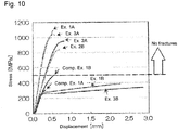
- Tensile strength of metal foil of even the same composition and same thickness may vary according to whether or not to be work-hardened and whether or not to be heat-treated (annealed) as shown in Fig. 10 . It was found that the copper alloy foil according to Examples 1 to 3 was material having such potential that tensile strength thereof greatly exceeded 500 MPa as shown in Fig. 10 , and was able to sufficiently bear roll press when an anode was produced. That is, it can be said that an alloy constituting an anode current collector layer preferably contains copper, and at least one selected from zinc, beryllium and tin.
- An anode mixture layer was formed over a surface of metal foil through the same procedures as those in the evaluation of the tensile strength, and thereafter was roll-pressed at such a maximum linear pressure (5 t/cm) and feed speed of 0.5 m/min that the filling factor of the anode mixture layer was improved while properties of material of the anode mixture layer was kept.
- an anode current collector layer preferably satisfies at least one of the following requirements (1) and (2) in order to suppress fractures of the anode current collector layer in roll press when an anode is produced:
- a sulfide solid-state battery including the anode of the present disclosure can be preferably used as a power source in a wide range such as a small-sized power source for portable devices and an onboard large-sized power source.
Landscapes
- Chemical & Material Sciences (AREA)
- Electrochemistry (AREA)
- General Chemical & Material Sciences (AREA)
- Chemical Kinetics & Catalysis (AREA)
- Engineering & Computer Science (AREA)
- Materials Engineering (AREA)
- Manufacturing & Machinery (AREA)
- Inorganic Chemistry (AREA)
- Physics & Mathematics (AREA)
- Condensed Matter Physics & Semiconductors (AREA)
- General Physics & Mathematics (AREA)
- Composite Materials (AREA)
- Cell Electrode Carriers And Collectors (AREA)
- Battery Electrode And Active Subsutance (AREA)
- Secondary Cells (AREA)
Applications Claiming Priority (2)
| Application Number | Priority Date | Filing Date | Title |
|---|---|---|---|
| JP2018065852 | 2018-03-29 | ||
| JP2018182465A JP2019175838A (ja) | 2018-03-29 | 2018-09-27 | 負極及び硫化物固体電池 |
Publications (1)
| Publication Number | Publication Date |
|---|---|
| EP3547424A1 true EP3547424A1 (de) | 2019-10-02 |
Family
ID=65324248
Family Applications (1)
| Application Number | Title | Priority Date | Filing Date |
|---|---|---|---|
| EP19155528.3A Pending EP3547424A1 (de) | 2018-03-29 | 2019-02-05 | Anode und sulfid-feststoffbatterie |
Country Status (4)
| Country | Link |
|---|---|
| US (1) | US11404685B2 (de) |
| EP (1) | EP3547424A1 (de) |
| CN (1) | CN110323412B (de) |
| BR (1) | BR102019005517A2 (de) |
Families Citing this family (3)
| Publication number | Priority date | Publication date | Assignee | Title |
|---|---|---|---|---|
| EP3869584A1 (de) * | 2020-02-18 | 2021-08-25 | Samsung Electronics Co., Ltd. | Festkörpersekundärbatterie und verfahren zur herstellung einer festkörpersekundärbatterie |
| CN112768756B (zh) * | 2021-01-13 | 2022-04-19 | 河北光兴半导体技术有限公司 | 固态电解质材料以及利用该材料制得的复合固态电解质和全固态电池 |
| EP4303951A1 (de) * | 2022-07-04 | 2024-01-10 | Saint-Gobain Ceramics&Plastics, Inc. | Pufferschicht für festkörperbatterien |
Citations (5)
| Publication number | Priority date | Publication date | Assignee | Title |
|---|---|---|---|---|
| US20090202908A1 (en) * | 2006-08-29 | 2009-08-13 | Masanori Sumihara | Current collector, electrode, and non-aqueous electrolyte secondary battery |
| JP2011060649A (ja) | 2009-09-11 | 2011-03-24 | Toyota Motor Corp | 電極活物質層、全固体電池、電極活物質層の製造方法および全固体電池の製造方法 |
| JP2012049023A (ja) | 2010-08-27 | 2012-03-08 | Toyota Motor Corp | 電池 |
| US20140346048A1 (en) * | 2012-03-02 | 2014-11-27 | Jx Nippon Mining & Metals Corporation | Electrolytic Copper Foil, and Negative Electrode Current Collector for Secondary Battery |
| US20160197351A1 (en) * | 2013-03-26 | 2016-07-07 | Furukawa Electric Co., Ltd. | All-solid-state secondary battery |
Family Cites Families (11)
| Publication number | Priority date | Publication date | Assignee | Title |
|---|---|---|---|---|
| JP2000208149A (ja) | 1999-01-18 | 2000-07-28 | Nippaku Sangyo Kk | 二次電池用負極集電体 |
| JP5535158B2 (ja) | 2010-09-17 | 2014-07-02 | 古河電気工業株式会社 | リチウムイオン二次電池用負極、リチウムイオン二次電池、およびリチウムイオン二次電池用負極の製造方法 |
| DE112013001595T5 (de) | 2012-03-22 | 2015-01-08 | Sumitomo Electric Industries, Ltd. | Festkörper-Lithiumsekundärbatterie |
| US10290855B2 (en) * | 2012-11-22 | 2019-05-14 | Nissan Motor Co., Ltd. | Negative electrode for electrical device, and electrical device using the same |
| CN102983336B (zh) * | 2012-11-30 | 2016-01-20 | 宁波市鄞州精艺机电厂 | 一种碱锰电池负极集流体及其制备方法 |
| JP5765349B2 (ja) | 2013-01-15 | 2015-08-19 | トヨタ自動車株式会社 | 全固体電池およびその製造方法 |
| CN103413905A (zh) * | 2013-07-12 | 2013-11-27 | 复旦大学 | 一种高电压的镁充放电电池 |
| JP6149657B2 (ja) | 2013-09-30 | 2017-06-21 | トヨタ自動車株式会社 | 全固体電池 |
| CN106058165B (zh) | 2015-04-02 | 2021-11-09 | 松下知识产权经营株式会社 | 电池和电池用电极材料 |
| JP6944773B2 (ja) * | 2016-09-26 | 2021-10-06 | 日産自動車株式会社 | 非水電解質二次電池用負極 |
| CN106784752B (zh) * | 2017-03-24 | 2019-11-22 | 北京工业大学 | 锂离子电池多孔结构Si/Cu复合电极及其制造方法 |
-
2019
- 2019-02-05 EP EP19155528.3A patent/EP3547424A1/de active Pending
- 2019-03-14 CN CN201910192925.3A patent/CN110323412B/zh active Active
- 2019-03-15 US US16/354,426 patent/US11404685B2/en active Active
- 2019-03-20 BR BR102019005517-0A patent/BR102019005517A2/pt not_active Application Discontinuation
Patent Citations (5)
| Publication number | Priority date | Publication date | Assignee | Title |
|---|---|---|---|---|
| US20090202908A1 (en) * | 2006-08-29 | 2009-08-13 | Masanori Sumihara | Current collector, electrode, and non-aqueous electrolyte secondary battery |
| JP2011060649A (ja) | 2009-09-11 | 2011-03-24 | Toyota Motor Corp | 電極活物質層、全固体電池、電極活物質層の製造方法および全固体電池の製造方法 |
| JP2012049023A (ja) | 2010-08-27 | 2012-03-08 | Toyota Motor Corp | 電池 |
| US20140346048A1 (en) * | 2012-03-02 | 2014-11-27 | Jx Nippon Mining & Metals Corporation | Electrolytic Copper Foil, and Negative Electrode Current Collector for Secondary Battery |
| US20160197351A1 (en) * | 2013-03-26 | 2016-07-07 | Furukawa Electric Co., Ltd. | All-solid-state secondary battery |
Non-Patent Citations (3)
| Title |
|---|
| DAVIS J R ED - DAVIS JOSEPH R (EDITOR): "ASM Speciality Handbook: Copper and Copper Alloys", 1 January 2001, ASM SPECIALTY HANDBOOK. COPPER AND COPPER ALLOYS; [ASM SPECIALTY HANDBOOK], MATERIALS PARK, OHIO : ASM INTERNATIONAL, USA, PAGE(S) 14 - 26, ISBN: 978-0-87170-726-0, XP002482353 * |
| HARNESS J C ET AL: "BERYLLIUM-COPPER AND OTHER BERYLLIUM-CONTAINING ALLOYS", 1 January 1990, PROPERTIES AND SELECTION : NONFERROUS ALLOYS AND SPECIAL PURPOSE MATERIALS; [METALS HANDBOOK], METALS PARK, ASM, US, PAGE(S) 403 - 423, XP002045188 * |
| PETR VAN: "Electrochemical Series", INTERNET CITATION, 1 January 2000 (2000-01-01), XP008169077, Retrieved from the Internet <URL:http://catedras.quimica.unlp.edu.ar/qa2/guias/Tablas.pdf> [retrieved on 20140428] * |
Also Published As
| Publication number | Publication date |
|---|---|
| BR102019005517A2 (pt) | 2019-10-08 |
| US11404685B2 (en) | 2022-08-02 |
| CN110323412B (zh) | 2022-10-14 |
| US20190305294A1 (en) | 2019-10-03 |
| CN110323412A (zh) | 2019-10-11 |
Similar Documents
| Publication | Publication Date | Title |
|---|---|---|
| JP6155327B2 (ja) | 全固体二次電池 | |
| CN109390552B (zh) | 全固态电池和负极 | |
| CN104919627B (zh) | 全固体电池及其制造方法 | |
| KR101823187B1 (ko) | 리튬이온 이차전지, 그 이차전지용 전극, 그 이차전지의 전극용 전해 동박 | |
| US10056607B2 (en) | Active material composite particle and lithium battery | |
| US11404685B2 (en) | Anode, and sulfide solid-state battery | |
| DE112012002904T5 (de) | Aktives Material für eine wiederaufladbare Batterie | |
| JP2009514164A (ja) | 二次電池用電極活物質 | |
| US10998540B2 (en) | Method for producing sulfide solid-state battery, and sulfide solid-state battery | |
| US20190296393A1 (en) | Sulfide solid-state battery | |
| RU2696596C1 (ru) | Анод и сульфидная твердотельная аккумуляторная батарея | |
| CN110165300B (zh) | 全固体电池的制造方法 | |
| CN115668534A (zh) | 电池及电池的制造方法 | |
| JP5345974B2 (ja) | 圧延銅合金箔、並びにこれを用いた負極集電体、負極板及び二次電池 | |
| CN111293353B (zh) | 用于固态电池的锂金属阳极的保护层 | |
| EP3496188B1 (de) | Verfahren zur herstellung einer festkörper-sulfid-batterie | |
| JP2021072259A (ja) | 全固体電池 | |
| JP2000011995A (ja) | 二次電池用正極板とその製造方法 | |
| JP7370728B2 (ja) | 全固体電池およびその製造方法 | |
| JP7227194B2 (ja) | 硫化物全固体電池 | |
| US20230178752A1 (en) | All-solid-state battery with intermediate layer containing metal sulfide | |
| EP4242267A1 (de) | Harzzusammensetzung, bindemittel für batterie, elektrodenmischungsschicht für batterie, elektrolytschicht, folie für batterie, batterie und harzzusammensetzungherstellungsverfahren | |
| KR20220129767A (ko) | 활물질이 없는 전고체 전지용 복합 음극 및 이의 제조방법 | |
| CN117242591A (zh) | 用于电化学电池的流变改性的浆液和由其制造的组分 | |
| KR20230124179A (ko) | 무음극 리튬이차전지 및 이의 제조방법 |
Legal Events
| Date | Code | Title | Description |
|---|---|---|---|
| PUAI | Public reference made under article 153(3) epc to a published international application that has entered the european phase |
Free format text: ORIGINAL CODE: 0009012 |
|
| STAA | Information on the status of an ep patent application or granted ep patent |
Free format text: STATUS: REQUEST FOR EXAMINATION WAS MADE |
|
| 17P | Request for examination filed |
Effective date: 20190205 |
|
| AK | Designated contracting states |
Kind code of ref document: A1 Designated state(s): AL AT BE BG CH CY CZ DE DK EE ES FI FR GB GR HR HU IE IS IT LI LT LU LV MC MK MT NL NO PL PT RO RS SE SI SK SM TR |
|
| AX | Request for extension of the european patent |
Extension state: BA ME |
|
| STAA | Information on the status of an ep patent application or granted ep patent |
Free format text: STATUS: EXAMINATION IS IN PROGRESS |
|
| 17Q | First examination report despatched |
Effective date: 20210503 |
|
| RIC1 | Information provided on ipc code assigned before grant |
Ipc: H01M 4/02 20060101ALN20231221BHEP Ipc: H01M 4/36 20060101ALN20231221BHEP Ipc: H01M 10/0562 20100101ALI20231221BHEP Ipc: H01M 10/052 20100101ALI20231221BHEP Ipc: H01M 4/134 20100101ALI20231221BHEP Ipc: H01M 4/62 20060101ALI20231221BHEP Ipc: H01M 4/58 20100101ALI20231221BHEP Ipc: H01M 4/38 20060101ALI20231221BHEP Ipc: H01M 4/66 20060101AFI20231221BHEP |
|
| GRAP | Despatch of communication of intention to grant a patent |
Free format text: ORIGINAL CODE: EPIDOSNIGR1 |
|
| STAA | Information on the status of an ep patent application or granted ep patent |
Free format text: STATUS: GRANT OF PATENT IS INTENDED |
|
| INTG | Intention to grant announced |
Effective date: 20240208 |