EP3496188B1 - Verfahren zur herstellung einer festkörper-sulfid-batterie - Google Patents
Verfahren zur herstellung einer festkörper-sulfid-batterie Download PDFInfo
- Publication number
- EP3496188B1 EP3496188B1 EP18201910.9A EP18201910A EP3496188B1 EP 3496188 B1 EP3496188 B1 EP 3496188B1 EP 18201910 A EP18201910 A EP 18201910A EP 3496188 B1 EP3496188 B1 EP 3496188B1
- Authority
- EP
- European Patent Office
- Prior art keywords
- anode
- sulfide solid
- lithium
- active material
- solid electrolyte
- Prior art date
- Legal status (The legal status is an assumption and is not a legal conclusion. Google has not performed a legal analysis and makes no representation as to the accuracy of the status listed.)
- Active
Links
- UCKMPCXJQFINFW-UHFFFAOYSA-N Sulphide Chemical compound [S-2] UCKMPCXJQFINFW-UHFFFAOYSA-N 0.000 title claims description 58
- 238000004519 manufacturing process Methods 0.000 title claims description 10
- 239000000463 material Substances 0.000 claims description 117
- 239000000203 mixture Substances 0.000 claims description 89
- 229910052744 lithium Inorganic materials 0.000 claims description 65
- WHXSMMKQMYFTQS-UHFFFAOYSA-N Lithium Chemical compound [Li] WHXSMMKQMYFTQS-UHFFFAOYSA-N 0.000 claims description 62
- RYGMFSIKBFXOCR-UHFFFAOYSA-N Copper Chemical compound [Cu] RYGMFSIKBFXOCR-UHFFFAOYSA-N 0.000 claims description 44
- 239000002203 sulfidic glass Substances 0.000 claims description 44
- 239000002409 silicon-based active material Substances 0.000 claims description 42
- OKTJSMMVPCPJKN-UHFFFAOYSA-N Carbon Chemical compound [C] OKTJSMMVPCPJKN-UHFFFAOYSA-N 0.000 claims description 36
- 229910002804 graphite Inorganic materials 0.000 claims description 29
- 239000010439 graphite Substances 0.000 claims description 29
- 238000000034 method Methods 0.000 claims description 29
- 239000010949 copper Substances 0.000 claims description 28
- 229910052802 copper Inorganic materials 0.000 claims description 27
- HBBGRARXTFLTSG-UHFFFAOYSA-N Lithium ion Chemical compound [Li+] HBBGRARXTFLTSG-UHFFFAOYSA-N 0.000 claims description 19
- 229910001416 lithium ion Inorganic materials 0.000 claims description 19
- RTAQQCXQSZGOHL-UHFFFAOYSA-N Titanium Chemical compound [Ti] RTAQQCXQSZGOHL-UHFFFAOYSA-N 0.000 claims description 17
- 238000002156 mixing Methods 0.000 claims description 17
- 238000003487 electrochemical reaction Methods 0.000 claims description 6
- 239000010410 layer Substances 0.000 description 44
- 239000007784 solid electrolyte Substances 0.000 description 39
- 239000011230 binding agent Substances 0.000 description 19
- 239000006182 cathode active material Substances 0.000 description 19
- 239000006183 anode active material Substances 0.000 description 18
- 239000002482 conductive additive Substances 0.000 description 18
- 239000011889 copper foil Substances 0.000 description 17
- 238000011156 evaluation Methods 0.000 description 16
- 239000002245 particle Substances 0.000 description 14
- 239000011888 foil Substances 0.000 description 13
- 229910052751 metal Inorganic materials 0.000 description 13
- 239000002184 metal Substances 0.000 description 13
- 230000000694 effects Effects 0.000 description 12
- 239000002904 solvent Substances 0.000 description 12
- 238000006243 chemical reaction Methods 0.000 description 9
- 239000007787 solid Substances 0.000 description 9
- 230000000052 comparative effect Effects 0.000 description 7
- 229910001220 stainless steel Inorganic materials 0.000 description 7
- 239000010935 stainless steel Substances 0.000 description 7
- 239000002033 PVDF binder Substances 0.000 description 6
- 229910052782 aluminium Inorganic materials 0.000 description 6
- XAGFODPZIPBFFR-UHFFFAOYSA-N aluminium Chemical compound [Al] XAGFODPZIPBFFR-UHFFFAOYSA-N 0.000 description 6
- XUPYJHCZDLZNFP-UHFFFAOYSA-N butyl butanoate Chemical compound CCCCOC(=O)CCC XUPYJHCZDLZNFP-UHFFFAOYSA-N 0.000 description 6
- 238000000576 coating method Methods 0.000 description 6
- 238000001035 drying Methods 0.000 description 6
- 239000003792 electrolyte Substances 0.000 description 6
- 229920002981 polyvinylidene fluoride Polymers 0.000 description 6
- 239000000243 solution Substances 0.000 description 6
- PXHVJJICTQNCMI-UHFFFAOYSA-N Nickel Chemical compound [Ni] PXHVJJICTQNCMI-UHFFFAOYSA-N 0.000 description 5
- XUIMIQQOPSSXEZ-UHFFFAOYSA-N Silicon Chemical compound [Si] XUIMIQQOPSSXEZ-UHFFFAOYSA-N 0.000 description 5
- 239000006230 acetylene black Substances 0.000 description 5
- 239000011149 active material Substances 0.000 description 5
- 239000010419 fine particle Substances 0.000 description 5
- 229910052710 silicon Inorganic materials 0.000 description 5
- 239000010703 silicon Substances 0.000 description 5
- 239000002002 slurry Substances 0.000 description 5
- SECXISVLQFMRJM-UHFFFAOYSA-N N-Methylpyrrolidone Chemical compound CN1CCCC1=O SECXISVLQFMRJM-UHFFFAOYSA-N 0.000 description 4
- 239000002134 carbon nanofiber Substances 0.000 description 4
- 239000000470 constituent Substances 0.000 description 4
- 229910000881 Cu alloy Inorganic materials 0.000 description 3
- XEEYBQQBJWHFJM-UHFFFAOYSA-N Iron Chemical compound [Fe] XEEYBQQBJWHFJM-UHFFFAOYSA-N 0.000 description 3
- 229910009297 Li2S-P2S5 Inorganic materials 0.000 description 3
- 229910009228 Li2S—P2S5 Inorganic materials 0.000 description 3
- VYPSYNLAJGMNEJ-UHFFFAOYSA-N Silicium dioxide Chemical compound O=[Si]=O VYPSYNLAJGMNEJ-UHFFFAOYSA-N 0.000 description 3
- 230000015572 biosynthetic process Effects 0.000 description 3
- 239000002388 carbon-based active material Substances 0.000 description 3
- 239000003575 carbonaceous material Substances 0.000 description 3
- 238000009792 diffusion process Methods 0.000 description 3
- 229910052759 nickel Inorganic materials 0.000 description 3
- 239000000843 powder Substances 0.000 description 3
- 229910052814 silicon oxide Inorganic materials 0.000 description 3
- 229920002134 Carboxymethyl cellulose Polymers 0.000 description 2
- LFQSCWFLJHTTHZ-UHFFFAOYSA-N Ethanol Chemical compound CCO LFQSCWFLJHTTHZ-UHFFFAOYSA-N 0.000 description 2
- 229910010827 LiI—Li2O—Li2S—P2S5 Inorganic materials 0.000 description 2
- 229910001290 LiPF6 Inorganic materials 0.000 description 2
- IMNFDUFMRHMDMM-UHFFFAOYSA-N N-Heptane Chemical compound CCCCCCC IMNFDUFMRHMDMM-UHFFFAOYSA-N 0.000 description 2
- 229920000459 Nitrile rubber Polymers 0.000 description 2
- 229910019142 PO4 Inorganic materials 0.000 description 2
- 239000005062 Polybutadiene Substances 0.000 description 2
- 239000002041 carbon nanotube Substances 0.000 description 2
- 229910021393 carbon nanotube Inorganic materials 0.000 description 2
- 238000005119 centrifugation Methods 0.000 description 2
- 239000011248 coating agent Substances 0.000 description 2
- 150000001875 compounds Chemical class 0.000 description 2
- 239000011521 glass Substances 0.000 description 2
- 229910003480 inorganic solid Inorganic materials 0.000 description 2
- 150000002500 ions Chemical class 0.000 description 2
- 229910052742 iron Inorganic materials 0.000 description 2
- 239000003273 ketjen black Substances 0.000 description 2
- 238000004898 kneading Methods 0.000 description 2
- 230000014759 maintenance of location Effects 0.000 description 2
- VNWKTOKETHGBQD-UHFFFAOYSA-N methane Chemical compound C VNWKTOKETHGBQD-UHFFFAOYSA-N 0.000 description 2
- 229910021382 natural graphite Inorganic materials 0.000 description 2
- 239000011255 nonaqueous electrolyte Substances 0.000 description 2
- 239000010452 phosphate Substances 0.000 description 2
- BASFCYQUMIYNBI-UHFFFAOYSA-N platinum Chemical compound [Pt] BASFCYQUMIYNBI-UHFFFAOYSA-N 0.000 description 2
- 229920002857 polybutadiene Polymers 0.000 description 2
- -1 polytetrafluoroethylene Polymers 0.000 description 2
- 229920001343 polytetrafluoroethylene Polymers 0.000 description 2
- 239000004810 polytetrafluoroethylene Substances 0.000 description 2
- XLYOFNOQVPJJNP-UHFFFAOYSA-N water Substances O XLYOFNOQVPJJNP-UHFFFAOYSA-N 0.000 description 2
- VYZAMTAEIAYCRO-UHFFFAOYSA-N Chromium Chemical compound [Cr] VYZAMTAEIAYCRO-UHFFFAOYSA-N 0.000 description 1
- PXGOKWXKJXAPGV-UHFFFAOYSA-N Fluorine Chemical compound FF PXGOKWXKJXAPGV-UHFFFAOYSA-N 0.000 description 1
- 229910000733 Li alloy Inorganic materials 0.000 description 1
- 229910003000 Li(Ni,Mn,Co)O2 Inorganic materials 0.000 description 1
- 229910006194 Li1+xAlxGe2-x(PO4)3 Inorganic materials 0.000 description 1
- 229910006196 Li1+xAlxGe2−x(PO4)3 Inorganic materials 0.000 description 1
- 229910009311 Li2S-SiS2 Inorganic materials 0.000 description 1
- 229910009225 Li2S—P2S5—GeS2 Inorganic materials 0.000 description 1
- 229910009433 Li2S—SiS2 Inorganic materials 0.000 description 1
- 229910002986 Li4Ti5O12 Inorganic materials 0.000 description 1
- 229910010835 LiI-Li2S-P2S5 Inorganic materials 0.000 description 1
- 229910010833 LiI-Li2S-SiS2 Inorganic materials 0.000 description 1
- 229910010842 LiI—Li2S—P2O5 Inorganic materials 0.000 description 1
- 229910010840 LiI—Li2S—P2S5 Inorganic materials 0.000 description 1
- 229910010855 LiI—Li2S—SiS2 Inorganic materials 0.000 description 1
- 229910010847 LiI—Li3PO4-P2S5 Inorganic materials 0.000 description 1
- 229910010864 LiI—Li3PO4—P2S5 Inorganic materials 0.000 description 1
- 229910001305 LiMPO4 Inorganic materials 0.000 description 1
- 229910003327 LiNbO3 Inorganic materials 0.000 description 1
- 229910014422 LiNi1/3Mn1/3Co1/3O2 Inorganic materials 0.000 description 1
- 229910012305 LiPON Inorganic materials 0.000 description 1
- 229910019651 Nb(OC2H5)5 Inorganic materials 0.000 description 1
- 229910015222 Ni1/3Mn1/3Co1/3O2 Inorganic materials 0.000 description 1
- 229910000676 Si alloy Inorganic materials 0.000 description 1
- HCHKCACWOHOZIP-UHFFFAOYSA-N Zinc Chemical compound [Zn] HCHKCACWOHOZIP-UHFFFAOYSA-N 0.000 description 1
- RJEIKIOYHOOKDL-UHFFFAOYSA-N [Li].[La] Chemical compound [Li].[La] RJEIKIOYHOOKDL-UHFFFAOYSA-N 0.000 description 1
- 239000000654 additive Substances 0.000 description 1
- 238000004458 analytical method Methods 0.000 description 1
- 239000012300 argon atmosphere Substances 0.000 description 1
- 229910021383 artificial graphite Inorganic materials 0.000 description 1
- 238000004364 calculation method Methods 0.000 description 1
- 239000001768 carboxy methyl cellulose Substances 0.000 description 1
- 235000010948 carboxy methyl cellulose Nutrition 0.000 description 1
- 239000008112 carboxymethyl-cellulose Substances 0.000 description 1
- 229910052804 chromium Inorganic materials 0.000 description 1
- 239000011651 chromium Substances 0.000 description 1
- 239000011247 coating layer Substances 0.000 description 1
- 239000002131 composite material Substances 0.000 description 1
- 230000008602 contraction Effects 0.000 description 1
- QHGJSLXSVXVKHZ-UHFFFAOYSA-N dilithium;dioxido(dioxo)manganese Chemical compound [Li+].[Li+].[O-][Mn]([O-])(=O)=O QHGJSLXSVXVKHZ-UHFFFAOYSA-N 0.000 description 1
- 238000007580 dry-mixing Methods 0.000 description 1
- 229920001971 elastomer Polymers 0.000 description 1
- 239000008151 electrolyte solution Substances 0.000 description 1
- 238000005430 electron energy loss spectroscopy Methods 0.000 description 1
- 238000000921 elemental analysis Methods 0.000 description 1
- 239000000835 fiber Substances 0.000 description 1
- 239000010408 film Substances 0.000 description 1
- 239000011737 fluorine Substances 0.000 description 1
- 229910052731 fluorine Inorganic materials 0.000 description 1
- PCHJSUWPFVWCPO-UHFFFAOYSA-N gold Chemical compound [Au] PCHJSUWPFVWCPO-UHFFFAOYSA-N 0.000 description 1
- 229910052737 gold Inorganic materials 0.000 description 1
- 239000010931 gold Substances 0.000 description 1
- 239000008187 granular material Substances 0.000 description 1
- 239000002391 graphite-based active material Substances 0.000 description 1
- 229910021385 hard carbon Inorganic materials 0.000 description 1
- 238000005342 ion exchange Methods 0.000 description 1
- 239000001989 lithium alloy Substances 0.000 description 1
- GQYHUHYESMUTHG-UHFFFAOYSA-N lithium niobate Chemical compound [Li+].[O-][Nb](=O)=O GQYHUHYESMUTHG-UHFFFAOYSA-N 0.000 description 1
- 229910001386 lithium phosphate Inorganic materials 0.000 description 1
- 229910052748 manganese Inorganic materials 0.000 description 1
- 238000004949 mass spectrometry Methods 0.000 description 1
- 239000007769 metal material Substances 0.000 description 1
- 239000012046 mixed solvent Substances 0.000 description 1
- 238000000465 moulding Methods 0.000 description 1
- 239000003960 organic solvent Substances 0.000 description 1
- 235000011837 pasties Nutrition 0.000 description 1
- NBIIXXVUZAFLBC-UHFFFAOYSA-K phosphate Chemical compound [O-]P([O-])([O-])=O NBIIXXVUZAFLBC-UHFFFAOYSA-K 0.000 description 1
- 229910052697 platinum Inorganic materials 0.000 description 1
- 239000002994 raw material Substances 0.000 description 1
- 239000005060 rubber Substances 0.000 description 1
- LIVNPJMFVYWSIS-UHFFFAOYSA-N silicon monoxide Chemical compound [Si-]#[O+] LIVNPJMFVYWSIS-UHFFFAOYSA-N 0.000 description 1
- 238000003980 solgel method Methods 0.000 description 1
- 229910052596 spinel Inorganic materials 0.000 description 1
- 239000011029 spinel Substances 0.000 description 1
- 229920003048 styrene butadiene rubber Polymers 0.000 description 1
- 238000005486 sulfidation Methods 0.000 description 1
- 125000000383 tetramethylene group Chemical group [H]C([H])([*:1])C([H])([H])C([H])([H])C([H])([H])[*:2] 0.000 description 1
- 239000002562 thickening agent Substances 0.000 description 1
- 239000010409 thin film Substances 0.000 description 1
- 238000005011 time of flight secondary ion mass spectroscopy Methods 0.000 description 1
- 239000010936 titanium Substances 0.000 description 1
- 229910052719 titanium Inorganic materials 0.000 description 1
- TWQULNDIKKJZPH-UHFFFAOYSA-K trilithium;phosphate Chemical compound [Li+].[Li+].[Li+].[O-]P([O-])([O-])=O TWQULNDIKKJZPH-UHFFFAOYSA-K 0.000 description 1
- 229910052725 zinc Inorganic materials 0.000 description 1
- 239000011701 zinc Substances 0.000 description 1
Images


Classifications
-
- H—ELECTRICITY
- H01—ELECTRIC ELEMENTS
- H01M—PROCESSES OR MEANS, e.g. BATTERIES, FOR THE DIRECT CONVERSION OF CHEMICAL ENERGY INTO ELECTRICAL ENERGY
- H01M4/00—Electrodes
- H01M4/02—Electrodes composed of, or comprising, active material
- H01M4/04—Processes of manufacture in general
- H01M4/0402—Methods of deposition of the material
- H01M4/0404—Methods of deposition of the material by coating on electrode collectors
-
- H—ELECTRICITY
- H01—ELECTRIC ELEMENTS
- H01M—PROCESSES OR MEANS, e.g. BATTERIES, FOR THE DIRECT CONVERSION OF CHEMICAL ENERGY INTO ELECTRICAL ENERGY
- H01M10/00—Secondary cells; Manufacture thereof
- H01M10/05—Accumulators with non-aqueous electrolyte
- H01M10/052—Li-accumulators
-
- H—ELECTRICITY
- H01—ELECTRIC ELEMENTS
- H01M—PROCESSES OR MEANS, e.g. BATTERIES, FOR THE DIRECT CONVERSION OF CHEMICAL ENERGY INTO ELECTRICAL ENERGY
- H01M10/00—Secondary cells; Manufacture thereof
- H01M10/05—Accumulators with non-aqueous electrolyte
- H01M10/052—Li-accumulators
- H01M10/0525—Rocking-chair batteries, i.e. batteries with lithium insertion or intercalation in both electrodes; Lithium-ion batteries
-
- H—ELECTRICITY
- H01—ELECTRIC ELEMENTS
- H01M—PROCESSES OR MEANS, e.g. BATTERIES, FOR THE DIRECT CONVERSION OF CHEMICAL ENERGY INTO ELECTRICAL ENERGY
- H01M10/00—Secondary cells; Manufacture thereof
- H01M10/05—Accumulators with non-aqueous electrolyte
- H01M10/056—Accumulators with non-aqueous electrolyte characterised by the materials used as electrolytes, e.g. mixed inorganic/organic electrolytes
- H01M10/0561—Accumulators with non-aqueous electrolyte characterised by the materials used as electrolytes, e.g. mixed inorganic/organic electrolytes the electrolyte being constituted of inorganic materials only
- H01M10/0562—Solid materials
-
- H—ELECTRICITY
- H01—ELECTRIC ELEMENTS
- H01M—PROCESSES OR MEANS, e.g. BATTERIES, FOR THE DIRECT CONVERSION OF CHEMICAL ENERGY INTO ELECTRICAL ENERGY
- H01M10/00—Secondary cells; Manufacture thereof
- H01M10/05—Accumulators with non-aqueous electrolyte
- H01M10/058—Construction or manufacture
-
- H—ELECTRICITY
- H01—ELECTRIC ELEMENTS
- H01M—PROCESSES OR MEANS, e.g. BATTERIES, FOR THE DIRECT CONVERSION OF CHEMICAL ENERGY INTO ELECTRICAL ENERGY
- H01M10/00—Secondary cells; Manufacture thereof
- H01M10/05—Accumulators with non-aqueous electrolyte
- H01M10/058—Construction or manufacture
- H01M10/0585—Construction or manufacture of accumulators having only flat construction elements, i.e. flat positive electrodes, flat negative electrodes and flat separators
-
- H—ELECTRICITY
- H01—ELECTRIC ELEMENTS
- H01M—PROCESSES OR MEANS, e.g. BATTERIES, FOR THE DIRECT CONVERSION OF CHEMICAL ENERGY INTO ELECTRICAL ENERGY
- H01M4/00—Electrodes
- H01M4/02—Electrodes composed of, or comprising, active material
- H01M4/13—Electrodes for accumulators with non-aqueous electrolyte, e.g. for lithium-accumulators; Processes of manufacture thereof
- H01M4/133—Electrodes based on carbonaceous material, e.g. graphite-intercalation compounds or CFx
-
- H—ELECTRICITY
- H01—ELECTRIC ELEMENTS
- H01M—PROCESSES OR MEANS, e.g. BATTERIES, FOR THE DIRECT CONVERSION OF CHEMICAL ENERGY INTO ELECTRICAL ENERGY
- H01M4/00—Electrodes
- H01M4/02—Electrodes composed of, or comprising, active material
- H01M4/13—Electrodes for accumulators with non-aqueous electrolyte, e.g. for lithium-accumulators; Processes of manufacture thereof
- H01M4/134—Electrodes based on metals, Si or alloys
-
- H—ELECTRICITY
- H01—ELECTRIC ELEMENTS
- H01M—PROCESSES OR MEANS, e.g. BATTERIES, FOR THE DIRECT CONVERSION OF CHEMICAL ENERGY INTO ELECTRICAL ENERGY
- H01M4/00—Electrodes
- H01M4/02—Electrodes composed of, or comprising, active material
- H01M4/13—Electrodes for accumulators with non-aqueous electrolyte, e.g. for lithium-accumulators; Processes of manufacture thereof
- H01M4/139—Processes of manufacture
- H01M4/1391—Processes of manufacture of electrodes based on mixed oxides or hydroxides, or on mixtures of oxides or hydroxides, e.g. LiCoOx
-
- H—ELECTRICITY
- H01—ELECTRIC ELEMENTS
- H01M—PROCESSES OR MEANS, e.g. BATTERIES, FOR THE DIRECT CONVERSION OF CHEMICAL ENERGY INTO ELECTRICAL ENERGY
- H01M4/00—Electrodes
- H01M4/02—Electrodes composed of, or comprising, active material
- H01M4/13—Electrodes for accumulators with non-aqueous electrolyte, e.g. for lithium-accumulators; Processes of manufacture thereof
- H01M4/139—Processes of manufacture
- H01M4/1393—Processes of manufacture of electrodes based on carbonaceous material, e.g. graphite-intercalation compounds or CFx
-
- H—ELECTRICITY
- H01—ELECTRIC ELEMENTS
- H01M—PROCESSES OR MEANS, e.g. BATTERIES, FOR THE DIRECT CONVERSION OF CHEMICAL ENERGY INTO ELECTRICAL ENERGY
- H01M4/00—Electrodes
- H01M4/02—Electrodes composed of, or comprising, active material
- H01M4/13—Electrodes for accumulators with non-aqueous electrolyte, e.g. for lithium-accumulators; Processes of manufacture thereof
- H01M4/139—Processes of manufacture
- H01M4/1395—Processes of manufacture of electrodes based on metals, Si or alloys
-
- H—ELECTRICITY
- H01—ELECTRIC ELEMENTS
- H01M—PROCESSES OR MEANS, e.g. BATTERIES, FOR THE DIRECT CONVERSION OF CHEMICAL ENERGY INTO ELECTRICAL ENERGY
- H01M4/00—Electrodes
- H01M4/02—Electrodes composed of, or comprising, active material
- H01M4/13—Electrodes for accumulators with non-aqueous electrolyte, e.g. for lithium-accumulators; Processes of manufacture thereof
- H01M4/139—Processes of manufacture
- H01M4/1397—Processes of manufacture of electrodes based on inorganic compounds other than oxides or hydroxides, e.g. sulfides, selenides, tellurides, halogenides or LiCoFy
-
- H—ELECTRICITY
- H01—ELECTRIC ELEMENTS
- H01M—PROCESSES OR MEANS, e.g. BATTERIES, FOR THE DIRECT CONVERSION OF CHEMICAL ENERGY INTO ELECTRICAL ENERGY
- H01M4/00—Electrodes
- H01M4/02—Electrodes composed of, or comprising, active material
- H01M4/36—Selection of substances as active materials, active masses, active liquids
- H01M4/362—Composites
- H01M4/364—Composites as mixtures
-
- H—ELECTRICITY
- H01—ELECTRIC ELEMENTS
- H01M—PROCESSES OR MEANS, e.g. BATTERIES, FOR THE DIRECT CONVERSION OF CHEMICAL ENERGY INTO ELECTRICAL ENERGY
- H01M4/00—Electrodes
- H01M4/02—Electrodes composed of, or comprising, active material
- H01M4/36—Selection of substances as active materials, active masses, active liquids
- H01M4/38—Selection of substances as active materials, active masses, active liquids of elements or alloys
- H01M4/386—Silicon or alloys based on silicon
-
- H—ELECTRICITY
- H01—ELECTRIC ELEMENTS
- H01M—PROCESSES OR MEANS, e.g. BATTERIES, FOR THE DIRECT CONVERSION OF CHEMICAL ENERGY INTO ELECTRICAL ENERGY
- H01M4/00—Electrodes
- H01M4/02—Electrodes composed of, or comprising, active material
- H01M4/36—Selection of substances as active materials, active masses, active liquids
- H01M4/48—Selection of substances as active materials, active masses, active liquids of inorganic oxides or hydroxides
- H01M4/485—Selection of substances as active materials, active masses, active liquids of inorganic oxides or hydroxides of mixed oxides or hydroxides for inserting or intercalating light metals, e.g. LiTi2O4 or LiTi2OxFy
-
- H—ELECTRICITY
- H01—ELECTRIC ELEMENTS
- H01M—PROCESSES OR MEANS, e.g. BATTERIES, FOR THE DIRECT CONVERSION OF CHEMICAL ENERGY INTO ELECTRICAL ENERGY
- H01M4/00—Electrodes
- H01M4/02—Electrodes composed of, or comprising, active material
- H01M4/36—Selection of substances as active materials, active masses, active liquids
- H01M4/58—Selection of substances as active materials, active masses, active liquids of inorganic compounds other than oxides or hydroxides, e.g. sulfides, selenides, tellurides, halogenides or LiCoFy; of polyanionic structures, e.g. phosphates, silicates or borates
- H01M4/583—Carbonaceous material, e.g. graphite-intercalation compounds or CFx
- H01M4/587—Carbonaceous material, e.g. graphite-intercalation compounds or CFx for inserting or intercalating light metals
-
- H—ELECTRICITY
- H01—ELECTRIC ELEMENTS
- H01M—PROCESSES OR MEANS, e.g. BATTERIES, FOR THE DIRECT CONVERSION OF CHEMICAL ENERGY INTO ELECTRICAL ENERGY
- H01M4/00—Electrodes
- H01M4/02—Electrodes composed of, or comprising, active material
- H01M2004/026—Electrodes composed of, or comprising, active material characterised by the polarity
- H01M2004/027—Negative electrodes
-
- H—ELECTRICITY
- H01—ELECTRIC ELEMENTS
- H01M—PROCESSES OR MEANS, e.g. BATTERIES, FOR THE DIRECT CONVERSION OF CHEMICAL ENERGY INTO ELECTRICAL ENERGY
- H01M2300/00—Electrolytes
- H01M2300/0017—Non-aqueous electrolytes
- H01M2300/0065—Solid electrolytes
- H01M2300/0068—Solid electrolytes inorganic
-
- Y—GENERAL TAGGING OF NEW TECHNOLOGICAL DEVELOPMENTS; GENERAL TAGGING OF CROSS-SECTIONAL TECHNOLOGIES SPANNING OVER SEVERAL SECTIONS OF THE IPC; TECHNICAL SUBJECTS COVERED BY FORMER USPC CROSS-REFERENCE ART COLLECTIONS [XRACs] AND DIGESTS
- Y02—TECHNOLOGIES OR APPLICATIONS FOR MITIGATION OR ADAPTATION AGAINST CLIMATE CHANGE
- Y02E—REDUCTION OF GREENHOUSE GAS [GHG] EMISSIONS, RELATED TO ENERGY GENERATION, TRANSMISSION OR DISTRIBUTION
- Y02E60/00—Enabling technologies; Technologies with a potential or indirect contribution to GHG emissions mitigation
- Y02E60/10—Energy storage using batteries
-
- Y—GENERAL TAGGING OF NEW TECHNOLOGICAL DEVELOPMENTS; GENERAL TAGGING OF CROSS-SECTIONAL TECHNOLOGIES SPANNING OVER SEVERAL SECTIONS OF THE IPC; TECHNICAL SUBJECTS COVERED BY FORMER USPC CROSS-REFERENCE ART COLLECTIONS [XRACs] AND DIGESTS
- Y02—TECHNOLOGIES OR APPLICATIONS FOR MITIGATION OR ADAPTATION AGAINST CLIMATE CHANGE
- Y02P—CLIMATE CHANGE MITIGATION TECHNOLOGIES IN THE PRODUCTION OR PROCESSING OF GOODS
- Y02P70/00—Climate change mitigation technologies in the production process for final industrial or consumer products
- Y02P70/50—Manufacturing or production processes characterised by the final manufactured product
Definitions
- the present application discloses a method for producing a sulfide solid-state battery.
- Patent Literatures 1 to 3 disclose sulfide solid-state batteries including positive electrodes, negative electrodes, and solid electrolyte layers provided between the positive and negative electrodes.
- a negative electrode mixture including a sulfide solid electrolyte, a silicon-based active material, and a carbon-based active material is layered over a surface of a negative electrode current collector formed of copper, to obtain the negative electrode.
- lithium is supplied from the cathode to the anode to dope an anode active material with lithium before the sulfide solid-state battery has the use voltage at the first charge.
- Patent Literature 3 a sulfidation resistant layer is provided on a surface of an anode current collector before an anode mixture containing a sulfide solid electrolyte is layered over this surface.
- Documents JP2015115194 and US2015171428 disclose a method for producing a solid state battery comprising a sulfide electrolyte, in which the anode layer is obtained by mixing together inter alia silicon, prelithiated graphite and a sulfide solid electrolyte and applying the so-obtained slurry onto a copper current collector.
- Document US5595837 discloses a method for prelithiating a graphite active material.
- the standard electrode potential of a sulfide solid-state battery with respect to lithium is equivalent to the OCV of an active material before charge and discharge.
- the standard potential of the anode with respect to lithium is approximately 2.8 V.
- an anode mixture containing a silicon-based active material and a sulfide solid electrolyte is layered over a surface of an anode current collector containing copper to form an anode
- the sulfide solid electrolyte reacts with copper at the OCV of the silicon-based active material, and copper diffuses from the anode current collector via the sulfide solid electrolyte toward a cathode side.
- Producing a sulfide solid-state battery using such an anode might lead to self-discharges caused by minor short circuits of a cathode and the anode etc.
- the present application discloses, as one means for solving the above problem, a method for producing a sulfide solid-state battery, as defined in claim 1, the method comprising: a first step of doping at least one material selected from graphite and lithium titanate with lithium, to obtain a predoped material; a second step of mixing a sulfide solid electrolyte, a silicon-based active material, and the predoped material, to obtain an anode mixture; and a third step of layering the anode mixture over a surface of an anode current collector that contains copper, to obtain an anode.
- a ratio (X/Y) of a converted value (X) obtained by converting a total amount of lithium with which the predoped material included in the anode mixture is being doped, into capacity, to a total capacity (Y) of the silicon-based active material contained in the anode mixture is preferably no less than 0.0005.
- said at least one material is preferably doped with lithium using an electrochemical reaction in a lithium ion battery.
- an anode mixture is made by mixing a predetermined predoped material together with a silicon-based active material.
- lithium diffuses from the predoped material into the silicon-based active material, which leads to a lowering potential when the anode mixture is used for an anode. That is, reaction of a sulfide solid electrolyte with copper can be suppressed, diffusion of copper from an anode current collector via the sulfide solid electrolyte toward a cathode side can be suppressed, and self-discharges caused by minor short circuits of a cathode and the anode etc. can be suppressed.
- the predoped material is difficult to have bad effects on battery properties.
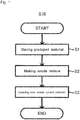
- the flow of a method for producing a sulfide solid-state battery 100 S10 will be described with reference to Figs. 1 to 3 .
- the method for producing the sulfide solid-state battery 100 S10 comprises: a first step S1 of doping at least one material 1 selected from graphite and lithium titanate with lithium, to obtain a predoped material 2; a second step S2 of mixing a sulfide solid electrolyte 3, a silicon-based active material 4, and the predoped material 2, to obtain an anode mixture 5; and a third step S3 of layering the anode mixture 5 over a surface of an anode current collector 6 that contains copper, to obtain an anode 10.
- At least one material 1 selected from graphite and lithium titanate is doped with lithium, to obtain the predoped material 2.
- the material 1 consists of at least one selected from graphite and lithium titanate (LTO). Both graphite and lithium titanate are materials that may store and release lithium, and are known as an anode active material for a lithium ion battery. When graphite and LTO are compared, graphite is preferable because the anode potential of graphite is low, which makes the effect of the technique of this disclosure more outstanding. This is also because the capacity of graphite is larger. This is also because graphite may perform well as a conductive additive as well. Any of artificial graphite and natural graphite may be the material 1.
- the composition of lithium titanate is not specifically limited, and for example, is preferably Li 4 Ti 5 O 12 .
- the shape of the material 1 is not specifically limited.
- the material 1 is especially preferably in the form of a particle.
- any way may be employed for doping the material 1 with lithium to obtain the predoped material 2.
- Examples thereof include a way of physically mixing the material 1 and a lithium source to dope the material 1 with lithium, and a way of electrochemically inserting lithium into the material 1.
- the material 1 is preferably doped with lithium using an electrochemical reaction in a lithium ion battery.
- one may preferably combine the material 1, a cathode active material that charges and discharges lithium ions at a potential nobler than the material 1, and some electrolyte having lithium ion conductivity, to form a lithium ion battery, and dope the material 1 with lithium using a charge reaction in the lithium ion battery.
- the lithium ion battery used in this case may be a battery of a solution system, and may be a solid-state battery.
- a battery of a solution system battery of a nonaqueous electrolyte solution system or an aqueous battery is preferably used.
- the material 1 is doped with lithium using an electrochemical reaction in the lithium ion battery, for example, the lithium ion battery is disassembled to strip off the predoped material 2, and the predoped material 2 is washed and ground if necessary.
- the doping amount of lithium in the material 1 is not specifically limited. It is believed that as the doping amount of lithium in the material 1 is increased, the amount of the predoped material 2 in the anode mixture 5 described later can be reduced.
- the material 1 is preferably doped with lithium until the charged capacity is no less than 10 mAh/g, which is more preferably no less than 50 mAh/g, further preferably no less than 80 mAh/g, and especially preferably no less than 100 mAh/g.
- the upper limit is not specifically limited, and is preferably no more than 200 mAh/g, more preferably no more than 180 mAh/g, and further preferably no more than 150 mAh/g.
- the battery is preferably charged until the SOC is no less than 5%, which is more preferably no less than 8%, and further preferably no less than 10%.
- the upper limit is not specifically limited, and is preferably no more than 50%.
- the sulfide solid electrolyte 3, the silicon-based active material 4, and the predoped material 2 are mixed, to obtain the anode mixture 5.
- Any sulfide used for a solid electrolyte for a sulfide solid-state battery can be employed for the sulfide solid electrolyte 3.
- Examples thereof include Li 2 S-P 2 S 5 , Li 2 S-SiS 2 , LiI-Li 2 S-SiS 2 , LiI-Si 2 S-P 2 S 5 , LiI-LiBr-Li 2 S-P 2 S 5 , LiI-Li 2 S-P 2 S 5 , LiI-Li 2 O-Li 2 S-P 2 S 5 , LiI-Li 2 S-P 2 O 5 , LiI-Li 3 PO 4 -P 2 S 5 , and Li 2 S-P 2 S 5 -GeS 2 .
- a sulfide solid electrolyte containing Li 2 S-P 2 S 5 is more preferable among them.
- One sulfide solid electrolyte may be used alone, or at least two sulfide solid electrolytes may be mixed to be used as the sulfide solid electrolyte 3.
- the amount of the sulfide solid electrolyte 3 is not specifically limited, and may be properly determined according to the performance of the battery to be aimed.
- the content of the sulfide solid electrolyte 3 is preferably 10 mass% to 60 mass% if the whole of the anode mixture 5 (the whole of the solid content after drying to remove solvent in the case of a wet mixing. Hereinafter the same.) is 100 mass%.
- the lower limit is more preferably no less than 20 mass%, and the upper limit is more preferably no more than 50 mass%.
- the silicon-based active material 4 has only to contain Si as a constituent element, and to function as an anode active material in the sulfide solid-state battery.
- Si a constituent element
- a Si alloy a silicon oxide
- Si or a silicon oxide is preferable.
- the shape of the silicon-based active material 4 is not specifically limited, and for example, the silicon-based active material 4 is preferably in the form of a particle.
- the amount of the silicon-based active material 4 is not specifically limited, and may be properly determined according to the performance of the battery to be aimed.
- the content of the silicon-based active material 4 is preferably 30 mass% to 90 mass% if the whole of the anode mixture 5 is 100 mass%.
- the lower limit is more preferably no less than 50 mass%, and the upper limit is more preferably no more than 80 mass%.
- the amount of the predoped material 2 is not specifically limited, and may be properly determined according to the doping amount of lithium in the first step S1 etc.
- the mixing ratio of the predoped material 2 and the silicon-based active material 4 is preferably determined so that the ratio (X/Y) of the converted value (X) obtained by converting the total amount of lithium with which the predoped material 2 included in the anode mixture 5 is being doped, into capacity, to the total capacity (Y) of the silicon-based active material 4 contained in the anode mixture 5 is no less than 0.0005.
- the ratio (X/Y) is more preferably no less than 0.0008.
- the ratio (X/Y) of no less than 0.0005 can lead to diffusion of a sufficient amount of lithium into the silicon-based active material 4, which makes it possible to further suppress self-discharges when the sulfide solid-state battery 100 is made.
- Converted value (X) obtained by converting the total amount of lithium with which the predoped material 2 included in the anode mixture 5 is being doped is a value obtained by converting the total amount of lithium that may diffuse from the predoped material 2 into the silicon-based active material 4 in the anode mixture 5 into capacity.
- the converted value (X) can be obtained from the charged capacity (Ah/g).
- Total capacity (Y) of the silicon-based active material 4 contained in the anode mixture 5" is a capacity that the silicon-based active material 4 contained in the anode mixture 5, which is under an uncharged state, has.
- Y can be a charge capacity of an active material which is obtained from the initial charge capacity obtained when a separately prepared mixture for measuring Y is charged and discharged in a cell using a Li counter electrode.
- a conductive additive is further mixed in the anode mixture 5 as far as the problem can be solved.
- a conductive additive employed for a sulfide solid-state battery can be employed.
- examples thereof include a carbon material such as acetylene black (AB), Ketjen black (KB), a vapor grown carbon fiber (VGCF), carbon nanotubes (CNT), a carbon nanofiber (CNF), and graphite; and a metallic material such as nickel, aluminum, and stainless steel.
- a carbon material is preferable.
- One conductive additive may be used individually, or two or more conductive additives may be mixed to be used. Any shape such as powder and fiber can be employed for the shape of the conductive additive.
- the amount of the conductive additive is not specifically limited, and may be properly determined according to the performance of the battery to be aimed.
- the content of the conductive additive is preferably 0.5 mass% to 20 mass% if the whole of the solid content of the anode mixture 5 is 100 mass%.
- the lower limit is more preferably no less than 1 mass%, and the upper limit is more preferably no more than 10 mass%.
- binder is further mixed in the anode mixture 5 as far as the problem can be solved.
- Any known one as binder employed for a sulfide solid-state battery can be employed.
- SBR styrene-butadiene rubber
- CMC carboxymethyl cellulose
- ABR acrylonitrile-butadiene rubber
- BR butadiene rubber
- PVDF polyvinylidene fluoride
- PTFE polytetrafluoroethylene
- the content of the binder is preferably 1 mass% to 30 mass% if the whole of the solid content of the anode mixture 5 is 100 mass%.
- the lower limit is more preferably no less than 2 mass%, and the upper limit is more preferably no more than 15 mass%.
- a solid electrolyte other than the sulfide solid electrolyte 3 may be further mixed in the anode mixture 5 as far as the problem can be solved.
- examples thereof include an oxide solid electrolyte such as lithium lanthanum zirconate, LiPON, Li 1+X Al X Ge 2-X (PO 4 ) 3 , Li-SiO-based glass, and Li-Al-S-O-based glass.
- an anode active material other than the silicon-based active material 4 may be further mixed in the anode mixture 5 as far as the problem can be solved.
- examples thereof include a carbon material such as graphite and hard carbon; various oxides such as lithium titanate; and lithium metal or a lithium alloy.
- the way of mixing the sulfide solid electrolyte 3, the silicon-based active material 4, and the predoped material 2 to form the anode mixture 5 is not specifically limited.
- the second step S2 can be performed using a known mixing means.
- the mixing in the second step S2 may be wet mixing using solvent, or dry mixing without solvent (mixing granular materials with each other). From the viewpoints that the materials can be mixed more uniformly, and that lithium can diffuse more properly from the predoped material 2 into the silicon-based active material 4, wet mixing using solvent is preferable.
- Solvent used in this case is not specifically limited. Preferred examples thereof include butyl butyrate and N-methylpyrrolidone (NMP).
- the anode mixture 5 is layered over the surface of the anode current collector 6 that contains copper, to obtain the anode 10.
- the anode current collector 6 only has to contain copper. Examples thereof include metal foil and a metal mesh which contain copper or a copper alloy. Or, the anode current collector 6 may be one whose base material is plated with copper or a copper alloy, or on a base material of which copper or a copper alloy is deposited. Specifically, metal foil formed of copper (copper foil) is preferable.
- the thickness of the anode current collector 6 is not specifically limited, and for example, is preferably 0.1 ⁇ m to 1 mm, and is more preferably 1 ⁇ m to 100 ⁇ m.
- the way of layering the anode mixture 5 over the surface of the anode current collector 6 is not specifically restricted.
- the anode mixture 5 is dispersed over solvent or the like, to be slurry or paste as described above.
- press-molding in the third step S3 leads to better contact among the sulfide solid electrolyte 3, the silicon-based active material 4, and the predoped material 2 in the anode mixture 5, which makes it possible to diffuse lithium more uniformly from the predoped material 2 into the silicon-based active material 4, and to exert a more outstanding effect.
- the thickness of the layer of the anode mixture 5 that is layered over the surface of the anode current collector 6 via the third step S3 is not specifically limited, and for example, is preferably 0.1 ⁇ m to 1 mm, and more preferably 1 ⁇ m to 100 ⁇ m. Or, the thickness can be thicker than this for improving capacity.
- the thickness of the layer of the anode mixture 5 is preferably determined so that the capacity of the anode 10 is larger than that of a cathode 20.
- the anode 10 of the sulfide solid-state battery 100 can be produced via the steps S1 to S3.
- a layer of an anode mixture that is different from the anode mixture 5 may be further provided over a face of the layer of the anode mixture 5 which is on the opposite side of the anode current collector 6 (face on a cathode side if the anode 10 is used in the battery).
- Examples thereof include layers containing only an active material other than a silicon-based active material (such as a carbon based active material) as an anode active material.
- the sulfide solid-state battery 100 includes the cathode 20 and a solid electrolyte layer 30 in addition to the anode 10 produced according to the steps S1 to S3.
- Methods for producing the cathode 20 and the solid electrolyte layer 30 are publicly known. That is, the sulfide solid-state battery 100 can be produced by the same method as a conventional one except that the method includes the producing method S10.
- the cathode 20 usually includes a cathode active material, and a cathode mixture layer 22 that contains, as optional constituents, a solid electrolyte, binder, a conductive additive, and other additives (thickener etc.).
- a cathode current collector 21 that is in contact with the cathode mixture layer 22 is preferably included.
- the cathode current collector 21 may be formed of metal foil, a metal mesh, or the like. Metal foil is especially preferable. Examples of metal that may constitute the cathode current collector include stainless steel, nickel, chromium, gold, platinum, aluminum, iron, titanium, zinc, etc.
- the cathode current collector 21 may be also metal foil which, or whose base material is plated with such metal or on which, or on the base material of which such metal is deposited.
- cathode active material for a sulfide solid-state battery
- a material displaying a nobler charge and discharge potential than that of the silicon-based active material 4 may be used as the cathode active material.
- examples thereof include a lithium containing oxide such as lithium cobaltate, lithium nickelate, Li(Ni,Mn,Co)O 2 (Li 1+ ⁇ Ni 1/3 Mn 1/3 Co 1/3 O 2 ), lithium manganate, a spinel lithium composite oxide, lithium titanate, and a lithium metal phosphate (LiMPO 4 where M is at least one selected from Fe, Mn, Co and Ni).
- One cathode active material may be used alone, or two or more cathode active materials may be mixed to be used.
- the cathode active material may have a coating layer of lithium niobate, lithium titanate, lithium phosphate, or the like over the surface thereof.
- the shape of the cathode active material is not specifically limited, and for example, the cathode active material is preferably in the form of a particle or a thin film.
- the content of the cathode active material in the cathode mixture layer is not specifically limited, and may be equivalent to the amount of a cathode active material contained in a cathode mixture layer of a conventional sulfide solid-state battery.
- any known one as a solid electrolyte for a sulfide solid-state battery can be employed. Preferred examples thereof include a sulfide solid electrolyte as described above.
- An inorganic solid electrolyte other than a sulfide solid electrolyte may be contained in addition to the sulfide solid electrolyte as far as a desired effect can be brought about.
- the same ones as in the anode 10 may be employed for the conductive additive and the binder as well.
- One solid electrolyte (conductive additive, binder) may be used alone, or two or more solid electrolytes (conductive additives, binders) may be mixed to be used.
- the shapes of the solid electrolyte and the conductive additive are not specifically limited, and for example, they are preferably in the form of a particle.
- the contents of the solid electrolyte, the conductive additive, and the binder in the cathode mixture layer are not specifically limited, and may be equivalent to those of a solid electrolyte, a conductive additive, and binder in a cathode mixture layer of a conventional sulfide solid-state battery.
- the cathode 20 having the structure described above can be easily produced by passing through steps such as putting the cathode active material, and the solid electrolyte, the binder, and the conductive additive which are optionally contained, into solvent, kneading them to obtain a slurry electrode composition, thereafter applying this electrode composition to a surface of the cathode current collector, and drying the surface.
- the cathode can be produced by not only such a wet process, but also a dry process.
- the thickness of the cathode mixture layer is, for example, preferably 0.1 ⁇ m to 1 mm, and more preferably 1 ⁇ m to 100 ⁇ m.
- the solid electrolyte layer 30 contains a solid electrolyte, and optionally binder.
- a sulfide solid electrolyte as described above is preferably employed for the solid electrolyte.
- an inorganic solid electrolyte other than a sulfide solid electrolyte may be contained in addition to the sulfide solid electrolyte as far as a desired effect can be brought about.
- the binder same as described above may be properly selected to be used.
- the contents of the constituents in the solid electrolyte layer 30 may be the same as in a conventional one.
- the shape of the solid electrolyte layer 30 may be the same as a conventional one as well. Specifically the solid electrolyte layer 30 in the form of a sheet is preferable.
- the solid electrolyte layer 30 in the form of a sheet can be easily produced by passing through steps such as putting the solid electrolyte, and optionally the binder into solvent, kneading them to obtain a slurry electrolyte composition, thereafter applying this electrolyte composition to a surface of a base material or to (a) surface(s) of the cathode mixture layer and/or the anode mixture layer, and drying the surface(s).
- the thickness of the solid electrolyte layer 30 is, for example, preferably 0.1 ⁇ m to 300 ⁇ m, and more preferably 0.1 ⁇ m to 100 ⁇ m.
- the sulfide solid-state battery 100 may include necessary terminals, battery case, etc. in addition to the anode 10, the cathode 20, and the solid electrolyte layer 30. These members are publicly known, and detailed description thereof is omitted here.
- the sulfide solid-state battery 100 that is produced via the producing method S10 of this disclosure has a structural feature as follows: that is, the sulfide solid-state battery 100 includes the anode 10, the cathode 20, and the solid electrolyte layer 30 provided between the anode 10 and the cathode 20, wherein the anode 10 includes a layer formed of the anode current collector 6 containing copper, and the anode mixture 5 provided over the surface of the anode current collector 6, the anode mixture 5 contains the sulfide solid electrolyte 3, the silicon-based active material 4, and the predoped material 2, and the predoped material 2 is obtained by doping the material 1, which is at least one selected from graphite and lithium titanate (preferably the material 1 consisting of graphite) with lithium.
- the structures of the members are as described above, and detailed description thereof is omitted here.
- the predetermined predoped material 2 is prepared in the first step S1, and the predoped material 2 is mixed together with the silicon-based active material 4 to make the anode mixture 5 in the second step S2.
- the silicon-based active material 4 is mixed together with the silicon-based active material 4 to make the anode mixture 5 in the second step S2.
- lithium diffuses from the predoped material 2 into the silicon-based active material 4, which leads to a lowering standard potential with respect to lithium if the mixture 5 is used for the anode 10.
- reaction of the sulfide solid electrolyte 3 with copper can be suppressed, diffusion of copper from the anode current collector 6 via the sulfide solid electrolyte 3 toward the cathode 20 side can be suppressed, and self-discharges caused by minor short circuits of the cathode 20 and the anode 10 etc. can be suppressed in the sulfide solid-state battery 100.
- the predoped material 2 is difficult to have bad effects on properties of the sulfide solid-state battery 100.
- a sulfide solid-state battery is produced by the producing method of this disclosure or not. That is, it can be confirmed whether a sulfide solid-state battery is produced by the producing method of this disclosure or not by, in a sulfide solid-state battery, analyzing part of an anode active material which does not face a cathode or an anode, or checking balance of cathode and anode potentials in a three electrode cell. Or, when a predoped material is obtained using an electrochemical reaction in a battery of a solution system, a SEI is formed over a surface of the predoped material.
- a sulfide solid-state battery is produced by the producing method of this disclosure or not as well by confirming whether graphite or lithium titanate contained in an anode has a SEI over its surface or not.
- compounds that may constitute a SEI include LiF, LiCO 3 , and a phosphate ester.
- Examples of the way of confirming the presence or not of compounds that may constitute a SEI include elemental analysis using TEM-EELS, ICP, and EPS, mass spectrometry using TOF-SIMS, and analysis of the combination thereof.
- whether this embodiment is performed or not can be determined by confirming that an element such as fluorine, which is not contained in raw materials of a solid electrolyte, is only contained in a SEI that is formed over a surface of a predoped material.
- LiNi 1/3 Mn 1/3 Co 1/3 O 2 particles (mean particle size (D 50 ): 6 ⁇ m) were prepared. LiNbO 3 was coated over surfaces of the particles by the sol-gel process. Specifically, an ethanol solution that dissolved equimolar LiOC 2 H 5 and Nb(OC 2 H 5 ) 5 was coated over the surfaces of the particles under an atmospheric pressure using a tumbling fluidized coating machine (SFP-01 manufactured by Powrex Corporation). The processing time was adjusted so that the thickness of this coating was 5 nm. Thereafter, the coated particles were heat-treated at 350°C under an atmospheric pressure for 1 hour, to obtain a cathode active material.
- SFP-01 tumbling fluidized coating machine
- a PVDF based binder manufactured by Kureha Corporation
- This coin cell was charged by means of a charge and discharge device. The charged capacity was adjusted so as to be 100 mAh/kg to the total weight of graphite contained in the coin cell. After the charge, the coin cell was disassembled under an argon atmosphere and the electrode was taken out. After the electrode was washed with EMC, graphite was stripped off from the copper foil by means of a spatula, to obtain a predoped material.
- the above described solid electrolyte layer was punched out to have 1 cm 2 in area, to be pressed at 1 ton/cm 2 .
- the cathode was piled on one face of the pressed solid electrolyte layer (face on the opposite side of the base material), to be pressed at 1 ton/cm 2 .
- the base material was stripped off.
- the anode was piled on the stripped face, to be pressed at 6 ton/cm 2 , to obtain a laminate formed of: cathode / solid electrolyte layer / anode.
- the obtained laminate was hermetically shut up in an aluminum laminated film having terminals, to obtain a sulfide solid-state battery for evaluation.
- the specifications of the obtained battery are shown in the following Table 1.
- a sulfide solid-state battery was made and subjected to self-discharge testing and evaluation of cycle characteristics in the same manner as in Example 1 except that the mixing ratio of the anode active material and the predoped material was changed as in the following Table 1.
- the specifications of the battery, and the results of the self-discharge testing and evaluation of cycle characteristics are shown in the following Table 1.
- a sulfide solid-state battery was made and subjected to self-discharge testing and evaluation of cycle characteristics in the same manner as in Example 1 except that the charged capacity when the predoped material was made was changed to 150 mAh/g.
- the specifications of the battery, and the results of the self-discharge testing and evaluation of cycle characteristics are shown in the following Table 1.
- a sulfide solid-state battery was made and subjected to self-discharge testing and evaluation of cycle characteristics in the same manner as in Example 1 except that the material used for the predoped material was changed from graphite to lithium titanate (mean particle size (D 50 ): 2 ⁇ m), to obtain the predoped material by the following procedures.
- the specifications of the battery, and the results of the self-discharge testing and evaluation of cycle characteristics are shown in the following Table 1.
- the stripped powder was dispersed into NMP of a volume approximately 10 times as large as the powder and subjected to centrifugation repeatedly three times to remove the PVDF-based binder etc. attached to lithium titanate. Fine particles obtained after the centrifugation were used as the predoped material.
- a sulfide solid-state battery was made and subjected to self-discharge testing and evaluation of cycle characteristics in the same manner as in Example 1 except that silicon was changed to a silicon oxide (mean particle size (D 50 ): 5 ⁇ m), and the weight of the obtained paste in the anode was changed.
- the specifications of the battery, and the results of the self-discharge testing and evaluation of cycle characteristics are shown in the following Table 1.
- a sulfide solid-state battery was made and subjected to self-discharge testing and evaluation of cycle characteristics in the same manner as in Example 1 except that the charged capacity when the predoped material was made was changed to 10 mAh/g, and the mixing ratio of the anode active material and the predoped material was changed as in the following Table 1.
- the specifications of the battery, and the results of the self-discharge testing and evaluation of cycle characteristics are shown in the following Table 1.
- a sulfide solid-state battery was made and subjected to self-discharge testing and evaluation of cycle characteristics in the same manner as in Comparative Example 1 except that stainless steel foil of the same thickness was used as the anode current collector instead of copper foil.
- the specifications of the battery, and the results of the self-discharge testing and evaluation of cycle characteristics are shown in the following Table 1.
- a sulfide solid-state battery was made and subjected to self-discharge testing and evaluation of cycle characteristics in the same manner as in Example 1 except that stainless steel foil of the same thickness was used as the anode current collector instead of copper foil.
- the specifications of the battery, and the results of the self-discharge testing and evaluation of cycle characteristics are shown in the following Table 1.
- Table 1 Weight of paste (mAh/g) Anode active material Predoped material Anode active material: predoped material (mass ratio) Converted value into capacity (X) / total capacity (Y) Self discharge ⁇ V (V) Cycle retention (%) Cathode Anode Kind Charged capacity (mAh/g) Ex. 1 25 5.6 Si Graphite 100 97:3 0.0008 0.18 86 Ex.
- the ratio (X/Y) of a converted value (X) obtained by converting the total amount of lithium with which the predoped material included in the anode mixture is being doped, into capacity, to the total capacity (Y) of the silicon-based active material contained in the anode mixture is preferably no less than 0.0005. Specifically, if X/Y is no less than 0.0008, when the self discharge is suppressed to be approximately 0.18 V is the limit of the effect of suppressing self-discharges.
- an anode active material is preferably no less than 70 mass% and less than 100 mass%, and a predoped material is preferably more than 0 mass% and no more than 30 mass%, if the total of the anode active material and the predoped material is 100 mass%.
- an anode active material may be more preferably no less than 90 mass%, further preferably no less than 93 mass%, and especially preferably no less than 96 mass%; and a predoped material may be more preferably no more than 10 mass%, further preferably no more than 7 mass%, and especially preferably no more than 4 mass%.
- anode mixture layer containing a silicon-based active material and a sulfide solid electrolyte is provided over a surface of an anode current collector, it is advantageous to use the anode current collector containing copper, and then contain a predetermined predoped material in an anode mixture, to suppress formation of CuS, compared with using the anode current collector formed of material other than copper to avoid CuS from forming.
- a sulfide solid-state battery produced according to the producing method of this disclosure may be used in a wide range of power sources such as a small-sized power source for portable devices and an onboard large-sized power source.
Claims (2)
- Verfahren zur Herstellung einer Sulfid-Festkörperbatterie (100), wobei das Verfahren umfasst:einen ersten Schritt des Dotierens mindestens eines Materials (1), ausgewählt aus Graphit und Lithiumtitanat, mit Lithium, um ein vordotiertes Material (2) zu erhalten;einen zweiten Schritt des Mischens eines Sulfid-Festelektrolyten (3), eines Aktivmaterials (4) auf Siliciumbasis und des vordotierten Materials (2), um eine Anodenmischung (5) zu erhalten; undeinen dritten Schritt des Aufbeschichtens der Anodenmischung (5) über eine Oberfläche eines Kupfer enthaltenden Anodenstromkollektors (6), um eine Anode (10) zu erhalten,wobei ein Verhältnis (X/Y) eines umgerechneten Wertes (X), der erhalten wird durch Umrechnen einer Gesamtmenge an Lithium, mit der das in der Anodenmischung (5) enthaltene vordotierte Material (2) dotiert wird, in eine Kapazität, zu einer Gesamtkapazität (Y) des in der Anodenmischung (5) enthaltenen Aktivmaterials (4) auf Siliciumbasis nicht weniger als 0,0005 beträgt.
- Verfahren nach Anspruch 1, wobei
im ersten Schritt das mindestens eine Material (1) unter Verwendung einer elektrochemischen Reaktion in einer Lithiumionenbatterie mit Lithium dotiert wird.
Applications Claiming Priority (2)
| Application Number | Priority Date | Filing Date | Title |
|---|---|---|---|
| JP2017236384 | 2017-12-08 | ||
| JP2018087219A JP6996414B2 (ja) | 2017-12-08 | 2018-04-27 | 硫化物固体電池の製造方法 |
Publications (2)
| Publication Number | Publication Date |
|---|---|
| EP3496188A1 EP3496188A1 (de) | 2019-06-12 |
| EP3496188B1 true EP3496188B1 (de) | 2021-03-31 |
Family
ID=63965312
Family Applications (1)
| Application Number | Title | Priority Date | Filing Date |
|---|---|---|---|
| EP18201910.9A Active EP3496188B1 (de) | 2017-12-08 | 2018-10-23 | Verfahren zur herstellung einer festkörper-sulfid-batterie |
Country Status (2)
| Country | Link |
|---|---|
| US (1) | US11075366B2 (de) |
| EP (1) | EP3496188B1 (de) |
Families Citing this family (3)
| Publication number | Priority date | Publication date | Assignee | Title |
|---|---|---|---|---|
| FR3080957B1 (fr) * | 2018-05-07 | 2020-07-10 | I-Ten | Electrodes mesoporeuses pour dispositifs electrochimiques en couches minces |
| US10797320B2 (en) * | 2018-09-11 | 2020-10-06 | Ford Global Technologies, Llc | Cell design to prevent over-discharge in li-ion batteries |
| CN112803077A (zh) * | 2021-02-04 | 2021-05-14 | 凌飞 | 铜基碳源固态电池芯、电池及其制作方法 |
Family Cites Families (11)
| Publication number | Priority date | Publication date | Assignee | Title |
|---|---|---|---|---|
| US5595837A (en) * | 1995-04-12 | 1997-01-21 | Valence Technology, Inc. | Process for prelithiation of carbon based anodes for lithium batteries |
| WO2011059766A1 (en) * | 2009-10-29 | 2011-05-19 | The Board Of Trustees Of The Leland Stanford Junior University | Devices, systems and methods for advanced rechargeable batteries |
| WO2014141962A1 (ja) * | 2013-03-11 | 2014-09-18 | 株式会社村田製作所 | 全固体電池 |
| CN105027346B (zh) | 2013-03-26 | 2017-11-21 | 古河电气工业株式会社 | 全固态二次电池 |
| JP2015032355A (ja) * | 2013-07-31 | 2015-02-16 | 日本碍子株式会社 | 全固体電池 |
| JP6278385B2 (ja) | 2013-11-02 | 2018-02-14 | 国立研究開発法人産業技術総合研究所 | 非水系二次電池のプリドープ方法及びプリドープ方法により得られる電池 |
| JP2015115194A (ja) * | 2013-12-11 | 2015-06-22 | 三星電子株式会社Samsung Electronics Co.,Ltd. | 全固体二次電池および全固体二次電池の製造方法 |
| JP6666641B2 (ja) | 2013-12-13 | 2020-03-18 | 三星電子株式会社Samsung Electronics Co.,Ltd. | 全固体二次電池および全固体二次電池の製造方法 |
| US9819019B2 (en) * | 2013-12-13 | 2017-11-14 | Samsung Electronics Co., Ltd. | All solid secondary battery and method of preparing all solid secondary battery |
| JP6497282B2 (ja) | 2015-09-10 | 2019-04-10 | トヨタ自動車株式会社 | 全固体電池用負極 |
| JP6409794B2 (ja) | 2016-02-18 | 2018-10-24 | トヨタ自動車株式会社 | 正極合剤の製造方法、正極の製造方法、及び全固体リチウムイオン二次電池の製造方法 |
-
2018
- 2018-10-23 EP EP18201910.9A patent/EP3496188B1/de active Active
- 2018-11-06 US US16/181,845 patent/US11075366B2/en active Active
Non-Patent Citations (1)
| Title |
|---|
| None * |
Also Published As
| Publication number | Publication date |
|---|---|
| US20190181420A1 (en) | 2019-06-13 |
| US11075366B2 (en) | 2021-07-27 |
| EP3496188A1 (de) | 2019-06-12 |
Similar Documents
| Publication | Publication Date | Title |
|---|---|---|
| Conder et al. | Electrochemical impedance spectroscopy of a Li–S battery: Part 1. Influence of the electrode and electrolyte compositions on the impedance of symmetric cells | |
| Tran et al. | Influence of electrode preparation on the electrochemical performance of LiNi0. 8Co0. 15Al0. 05O2 composite electrodes for lithium-ion batteries | |
| EP3226330B1 (de) | Positivelektrodenaktivmaterial für sekundärzelle mit wasserfreiem elektrolyten, verfahren zur herstellung davon und sekundärzelle mit wasserfreiem elektrolyten, in dem das besagte material verwendet wird | |
| RU2695127C1 (ru) | Способ изготовления сульфидных твердотельных батарей | |
| US11011321B2 (en) | Electrochemical energy storage device | |
| Wang et al. | Enhancing electrochemical properties of graphite anode by using poly (methylmethacrylate)–poly (vinylidene fluoride) composite binder | |
| EP3226331A1 (de) | Positivelektrodenaktivmaterial für sekundärbatterie mit wasserfreiem elektrolyten und herstellungsverfahren dafür und sekundärbatterie mit wasserfreiem elektrolyten mit verwendung des besagten positivelektrodenaktivmaterials | |
| JP2009193940A (ja) | 電極体及びその製造方法、並びに、リチウムイオン二次電池 | |
| EP3579324A1 (de) | Feststoffbatterie und herstellungsverfahren dafür | |
| Park et al. | Charge–discharge properties of tin dioxide for sodium-ion battery | |
| US10998540B2 (en) | Method for producing sulfide solid-state battery, and sulfide solid-state battery | |
| EP3496188B1 (de) | Verfahren zur herstellung einer festkörper-sulfid-batterie | |
| KR20160110045A (ko) | 활물질 복합 입자 및 리튬 전지 | |
| KR20150027026A (ko) | 리튬 이온 2차 전지의 전극 및 그 전극용 페이스트의 조제 방법 그리고 그 전극의 제작 방법 | |
| EP3576190A1 (de) | Kathode, feststoffbatterie und verfahren zur herstellung davon | |
| KR101352672B1 (ko) | 이차전지용 음극 활물질 | |
| JP2011159639A (ja) | 電極体及びその製造方法、並びに、リチウムイオン二次電池 | |
| Yang et al. | A significant enhancement of cycling stability at fast charging rate through incorporation of Li3N into LiF-based SEI in SiOx anode for Li-ion batteries | |
| EP3716372A1 (de) | Aktivmaterial einer positiven elektrode für sekundärbatterie mit wasserfreiem elektrolyt und verfahren zur herstellung von aktivmaterial einer positiven elektrode für sekundärbatterie mit wasserfreiem elektrolyt | |
| JP2012049124A (ja) | 非水電解質二次電池 | |
| EP3576209A1 (de) | Kathode, feststoffbatterie und verfahren zur herstellung davon | |
| EP3709397A1 (de) | Positivelektrode für batterie mit wasserfreiem elektrolyt und batterie mit wasserfreiem elektrolyt | |
| JPH10188955A (ja) | 電池用電極、電極の製造方法、及び電池 | |
| EP2631973B1 (de) | Elektrode für Lithiumsekundärbatterie, Herstellungsverfahren dafür und Lithiumsekundärbatterie damit | |
| US20220115691A1 (en) | Method for producing all solid-state battery, and all solid-state battery |
Legal Events
| Date | Code | Title | Description |
|---|---|---|---|
| PUAI | Public reference made under article 153(3) epc to a published international application that has entered the european phase |
Free format text: ORIGINAL CODE: 0009012 |
|
| STAA | Information on the status of an ep patent application or granted ep patent |
Free format text: STATUS: REQUEST FOR EXAMINATION WAS MADE |
|
| 17P | Request for examination filed |
Effective date: 20181023 |
|
| AK | Designated contracting states |
Kind code of ref document: A1 Designated state(s): AL AT BE BG CH CY CZ DE DK EE ES FI FR GB GR HR HU IE IS IT LI LT LU LV MC MK MT NL NO PL PT RO RS SE SI SK SM TR |
|
| AX | Request for extension of the european patent |
Extension state: BA ME |
|
| RIC1 | Information provided on ipc code assigned before grant |
Ipc: H01M 4/1393 20100101ALI20200904BHEP Ipc: H01M 4/583 20100101ALI20200904BHEP Ipc: H01M 4/1395 20100101ALI20200904BHEP Ipc: H01M 4/38 20060101ALI20200904BHEP Ipc: H01M 4/134 20100101ALI20200904BHEP Ipc: H01M 10/0562 20100101ALI20200904BHEP Ipc: H01M 10/058 20100101ALI20200904BHEP Ipc: H01M 10/052 20100101ALI20200904BHEP Ipc: H01M 4/133 20100101AFI20200904BHEP Ipc: H01M 4/36 20060101ALI20200904BHEP Ipc: H01M 4/02 20060101ALN20200904BHEP Ipc: H01M 4/485 20100101ALI20200904BHEP |
|
| GRAP | Despatch of communication of intention to grant a patent |
Free format text: ORIGINAL CODE: EPIDOSNIGR1 |
|
| STAA | Information on the status of an ep patent application or granted ep patent |
Free format text: STATUS: GRANT OF PATENT IS INTENDED |
|
| INTG | Intention to grant announced |
Effective date: 20201019 |
|
| GRAS | Grant fee paid |
Free format text: ORIGINAL CODE: EPIDOSNIGR3 |
|
| GRAA | (expected) grant |
Free format text: ORIGINAL CODE: 0009210 |
|
| STAA | Information on the status of an ep patent application or granted ep patent |
Free format text: STATUS: THE PATENT HAS BEEN GRANTED |
|
| AK | Designated contracting states |
Kind code of ref document: B1 Designated state(s): AL AT BE BG CH CY CZ DE DK EE ES FI FR GB GR HR HU IE IS IT LI LT LU LV MC MK MT NL NO PL PT RO RS SE SI SK SM TR |
|
| REG | Reference to a national code |
Ref country code: GB Ref legal event code: FG4D Ref country code: CH Ref legal event code: EP |
|
| REG | Reference to a national code |
Ref country code: AT Ref legal event code: REF Ref document number: 1377951 Country of ref document: AT Kind code of ref document: T Effective date: 20210415 |
|
| REG | Reference to a national code |
Ref country code: DE Ref legal event code: R096 Ref document number: 602018014659 Country of ref document: DE |
|
| REG | Reference to a national code |
Ref country code: IE Ref legal event code: FG4D |
|
| REG | Reference to a national code |
Ref country code: LT Ref legal event code: MG9D |
|
| PG25 | Lapsed in a contracting state [announced via postgrant information from national office to epo] |
Ref country code: BG Free format text: LAPSE BECAUSE OF FAILURE TO SUBMIT A TRANSLATION OF THE DESCRIPTION OR TO PAY THE FEE WITHIN THE PRESCRIBED TIME-LIMIT Effective date: 20210630 Ref country code: HR Free format text: LAPSE BECAUSE OF FAILURE TO SUBMIT A TRANSLATION OF THE DESCRIPTION OR TO PAY THE FEE WITHIN THE PRESCRIBED TIME-LIMIT Effective date: 20210331 Ref country code: FI Free format text: LAPSE BECAUSE OF FAILURE TO SUBMIT A TRANSLATION OF THE DESCRIPTION OR TO PAY THE FEE WITHIN THE PRESCRIBED TIME-LIMIT Effective date: 20210331 Ref country code: NO Free format text: LAPSE BECAUSE OF FAILURE TO SUBMIT A TRANSLATION OF THE DESCRIPTION OR TO PAY THE FEE WITHIN THE PRESCRIBED TIME-LIMIT Effective date: 20210630 |
|
| PG25 | Lapsed in a contracting state [announced via postgrant information from national office to epo] |
Ref country code: SE Free format text: LAPSE BECAUSE OF FAILURE TO SUBMIT A TRANSLATION OF THE DESCRIPTION OR TO PAY THE FEE WITHIN THE PRESCRIBED TIME-LIMIT Effective date: 20210331 Ref country code: RS Free format text: LAPSE BECAUSE OF FAILURE TO SUBMIT A TRANSLATION OF THE DESCRIPTION OR TO PAY THE FEE WITHIN THE PRESCRIBED TIME-LIMIT Effective date: 20210331 Ref country code: LV Free format text: LAPSE BECAUSE OF FAILURE TO SUBMIT A TRANSLATION OF THE DESCRIPTION OR TO PAY THE FEE WITHIN THE PRESCRIBED TIME-LIMIT Effective date: 20210331 |
|
| REG | Reference to a national code |
Ref country code: AT Ref legal event code: MK05 Ref document number: 1377951 Country of ref document: AT Kind code of ref document: T Effective date: 20210331 |
|
| PG25 | Lapsed in a contracting state [announced via postgrant information from national office to epo] |
Ref country code: SM Free format text: LAPSE BECAUSE OF FAILURE TO SUBMIT A TRANSLATION OF THE DESCRIPTION OR TO PAY THE FEE WITHIN THE PRESCRIBED TIME-LIMIT Effective date: 20210331 Ref country code: NL Free format text: LAPSE BECAUSE OF FAILURE TO SUBMIT A TRANSLATION OF THE DESCRIPTION OR TO PAY THE FEE WITHIN THE PRESCRIBED TIME-LIMIT Effective date: 20210331 Ref country code: AT Free format text: LAPSE BECAUSE OF FAILURE TO SUBMIT A TRANSLATION OF THE DESCRIPTION OR TO PAY THE FEE WITHIN THE PRESCRIBED TIME-LIMIT Effective date: 20210331 Ref country code: CZ Free format text: LAPSE BECAUSE OF FAILURE TO SUBMIT A TRANSLATION OF THE DESCRIPTION OR TO PAY THE FEE WITHIN THE PRESCRIBED TIME-LIMIT Effective date: 20210331 Ref country code: EE Free format text: LAPSE BECAUSE OF FAILURE TO SUBMIT A TRANSLATION OF THE DESCRIPTION OR TO PAY THE FEE WITHIN THE PRESCRIBED TIME-LIMIT Effective date: 20210331 Ref country code: LT Free format text: LAPSE BECAUSE OF FAILURE TO SUBMIT A TRANSLATION OF THE DESCRIPTION OR TO PAY THE FEE WITHIN THE PRESCRIBED TIME-LIMIT Effective date: 20210331 |
|
| PG25 | Lapsed in a contracting state [announced via postgrant information from national office to epo] |
Ref country code: IS Free format text: LAPSE BECAUSE OF FAILURE TO SUBMIT A TRANSLATION OF THE DESCRIPTION OR TO PAY THE FEE WITHIN THE PRESCRIBED TIME-LIMIT Effective date: 20210731 Ref country code: PT Free format text: LAPSE BECAUSE OF FAILURE TO SUBMIT A TRANSLATION OF THE DESCRIPTION OR TO PAY THE FEE WITHIN THE PRESCRIBED TIME-LIMIT Effective date: 20210802 Ref country code: PL Free format text: LAPSE BECAUSE OF FAILURE TO SUBMIT A TRANSLATION OF THE DESCRIPTION OR TO PAY THE FEE WITHIN THE PRESCRIBED TIME-LIMIT Effective date: 20210331 Ref country code: RO Free format text: LAPSE BECAUSE OF FAILURE TO SUBMIT A TRANSLATION OF THE DESCRIPTION OR TO PAY THE FEE WITHIN THE PRESCRIBED TIME-LIMIT Effective date: 20210331 Ref country code: SK Free format text: LAPSE BECAUSE OF FAILURE TO SUBMIT A TRANSLATION OF THE DESCRIPTION OR TO PAY THE FEE WITHIN THE PRESCRIBED TIME-LIMIT Effective date: 20210331 |
|
| REG | Reference to a national code |
Ref country code: DE Ref legal event code: R097 Ref document number: 602018014659 Country of ref document: DE |
|
| PG25 | Lapsed in a contracting state [announced via postgrant information from national office to epo] |
Ref country code: AL Free format text: LAPSE BECAUSE OF FAILURE TO SUBMIT A TRANSLATION OF THE DESCRIPTION OR TO PAY THE FEE WITHIN THE PRESCRIBED TIME-LIMIT Effective date: 20210331 Ref country code: DK Free format text: LAPSE BECAUSE OF FAILURE TO SUBMIT A TRANSLATION OF THE DESCRIPTION OR TO PAY THE FEE WITHIN THE PRESCRIBED TIME-LIMIT Effective date: 20210331 Ref country code: ES Free format text: LAPSE BECAUSE OF FAILURE TO SUBMIT A TRANSLATION OF THE DESCRIPTION OR TO PAY THE FEE WITHIN THE PRESCRIBED TIME-LIMIT Effective date: 20210331 |
|
| PLBE | No opposition filed within time limit |
Free format text: ORIGINAL CODE: 0009261 |
|
| STAA | Information on the status of an ep patent application or granted ep patent |
Free format text: STATUS: NO OPPOSITION FILED WITHIN TIME LIMIT |
|
| 26N | No opposition filed |
Effective date: 20220104 |
|
| REG | Reference to a national code |
Ref country code: CH Ref legal event code: PL |
|
| PG25 | Lapsed in a contracting state [announced via postgrant information from national office to epo] |
Ref country code: IS Free format text: LAPSE BECAUSE OF FAILURE TO SUBMIT A TRANSLATION OF THE DESCRIPTION OR TO PAY THE FEE WITHIN THE PRESCRIBED TIME-LIMIT Effective date: 20210731 |
|
| REG | Reference to a national code |
Ref country code: BE Ref legal event code: MM Effective date: 20211031 |
|
| PG25 | Lapsed in a contracting state [announced via postgrant information from national office to epo] |
Ref country code: MC Free format text: LAPSE BECAUSE OF FAILURE TO SUBMIT A TRANSLATION OF THE DESCRIPTION OR TO PAY THE FEE WITHIN THE PRESCRIBED TIME-LIMIT Effective date: 20210331 |
|
| PG25 | Lapsed in a contracting state [announced via postgrant information from national office to epo] |
Ref country code: LU Free format text: LAPSE BECAUSE OF NON-PAYMENT OF DUE FEES Effective date: 20211023 Ref country code: IT Free format text: LAPSE BECAUSE OF FAILURE TO SUBMIT A TRANSLATION OF THE DESCRIPTION OR TO PAY THE FEE WITHIN THE PRESCRIBED TIME-LIMIT Effective date: 20210331 Ref country code: BE Free format text: LAPSE BECAUSE OF NON-PAYMENT OF DUE FEES Effective date: 20211031 |
|
| PG25 | Lapsed in a contracting state [announced via postgrant information from national office to epo] |
Ref country code: LI Free format text: LAPSE BECAUSE OF NON-PAYMENT OF DUE FEES Effective date: 20211031 Ref country code: CH Free format text: LAPSE BECAUSE OF NON-PAYMENT OF DUE FEES Effective date: 20211031 |
|
| PG25 | Lapsed in a contracting state [announced via postgrant information from national office to epo] |
Ref country code: FR Free format text: LAPSE BECAUSE OF NON-PAYMENT OF DUE FEES Effective date: 20211031 |
|
| PG25 | Lapsed in a contracting state [announced via postgrant information from national office to epo] |
Ref country code: IE Free format text: LAPSE BECAUSE OF NON-PAYMENT OF DUE FEES Effective date: 20211023 |
|
| P01 | Opt-out of the competence of the unified patent court (upc) registered |
Effective date: 20230427 |
|
| GBPC | Gb: european patent ceased through non-payment of renewal fee |
Effective date: 20221023 |
|
| PG25 | Lapsed in a contracting state [announced via postgrant information from national office to epo] |
Ref country code: CY Free format text: LAPSE BECAUSE OF FAILURE TO SUBMIT A TRANSLATION OF THE DESCRIPTION OR TO PAY THE FEE WITHIN THE PRESCRIBED TIME-LIMIT Effective date: 20210331 |
|
| PG25 | Lapsed in a contracting state [announced via postgrant information from national office to epo] |
Ref country code: HU Free format text: LAPSE BECAUSE OF FAILURE TO SUBMIT A TRANSLATION OF THE DESCRIPTION OR TO PAY THE FEE WITHIN THE PRESCRIBED TIME-LIMIT; INVALID AB INITIO Effective date: 20181023 Ref country code: GR Free format text: LAPSE BECAUSE OF FAILURE TO SUBMIT A TRANSLATION OF THE DESCRIPTION OR TO PAY THE FEE WITHIN THE PRESCRIBED TIME-LIMIT Effective date: 20210331 |
|
| PG25 | Lapsed in a contracting state [announced via postgrant information from national office to epo] |
Ref country code: GB Free format text: LAPSE BECAUSE OF NON-PAYMENT OF DUE FEES Effective date: 20221023 |
|
| PGFP | Annual fee paid to national office [announced via postgrant information from national office to epo] |
Ref country code: DE Payment date: 20230830 Year of fee payment: 6 |
|
| PG25 | Lapsed in a contracting state [announced via postgrant information from national office to epo] |
Ref country code: MK Free format text: LAPSE BECAUSE OF FAILURE TO SUBMIT A TRANSLATION OF THE DESCRIPTION OR TO PAY THE FEE WITHIN THE PRESCRIBED TIME-LIMIT Effective date: 20210331 |