EP3546405B1 - Medientransportvorrichtung und dazugehörige nachverarbeitungsvorrichtung - Google Patents
Medientransportvorrichtung und dazugehörige nachverarbeitungsvorrichtung Download PDFInfo
- Publication number
- EP3546405B1 EP3546405B1 EP19166390.5A EP19166390A EP3546405B1 EP 3546405 B1 EP3546405 B1 EP 3546405B1 EP 19166390 A EP19166390 A EP 19166390A EP 3546405 B1 EP3546405 B1 EP 3546405B1
- Authority
- EP
- European Patent Office
- Prior art keywords
- medium
- transport belt
- transport
- flap
- stacker
- Prior art date
- Legal status (The legal status is an assumption and is not a legal conclusion. Google has not performed a legal analysis and makes no representation as to the accuracy of the status listed.)
- Active
Links
Images


Classifications
-
- B—PERFORMING OPERATIONS; TRANSPORTING
- B65—CONVEYING; PACKING; STORING; HANDLING THIN OR FILAMENTARY MATERIAL
- B65H—HANDLING THIN OR FILAMENTARY MATERIAL, e.g. SHEETS, WEBS, CABLES
- B65H31/00—Pile receivers
- B65H31/02—Pile receivers with stationary end support against which pile accumulates
-
- B—PERFORMING OPERATIONS; TRANSPORTING
- B65—CONVEYING; PACKING; STORING; HANDLING THIN OR FILAMENTARY MATERIAL
- B65H—HANDLING THIN OR FILAMENTARY MATERIAL, e.g. SHEETS, WEBS, CABLES
- B65H29/00—Delivering or advancing articles from machines; Advancing articles to or into piles
- B65H29/24—Delivering or advancing articles from machines; Advancing articles to or into piles by air blast or suction apparatus
- B65H29/241—Suction devices
- B65H29/242—Suction bands or belts
-
- B—PERFORMING OPERATIONS; TRANSPORTING
- B65—CONVEYING; PACKING; STORING; HANDLING THIN OR FILAMENTARY MATERIAL
- B65H—HANDLING THIN OR FILAMENTARY MATERIAL, e.g. SHEETS, WEBS, CABLES
- B65H29/00—Delivering or advancing articles from machines; Advancing articles to or into piles
- B65H29/54—Article strippers, e.g. for stripping from advancing elements
- B65H29/56—Article strippers, e.g. for stripping from advancing elements for stripping from elements or machines
-
- B—PERFORMING OPERATIONS; TRANSPORTING
- B65—CONVEYING; PACKING; STORING; HANDLING THIN OR FILAMENTARY MATERIAL
- B65H—HANDLING THIN OR FILAMENTARY MATERIAL, e.g. SHEETS, WEBS, CABLES
- B65H31/00—Pile receivers
- B65H31/30—Arrangements for removing completed piles
- B65H31/3027—Arrangements for removing completed piles by the nip between moving belts or rollers
-
- B—PERFORMING OPERATIONS; TRANSPORTING
- B65—CONVEYING; PACKING; STORING; HANDLING THIN OR FILAMENTARY MATERIAL
- B65H—HANDLING THIN OR FILAMENTARY MATERIAL, e.g. SHEETS, WEBS, CABLES
- B65H31/00—Pile receivers
- B65H31/34—Apparatus for squaring-up piled articles
- B65H31/36—Auxiliary devices for contacting each article with a front stop as it is piled
-
- B—PERFORMING OPERATIONS; TRANSPORTING
- B65—CONVEYING; PACKING; STORING; HANDLING THIN OR FILAMENTARY MATERIAL
- B65H—HANDLING THIN OR FILAMENTARY MATERIAL, e.g. SHEETS, WEBS, CABLES
- B65H2301/00—Handling processes for sheets or webs
- B65H2301/40—Type of handling process
- B65H2301/42—Piling, depiling, handling piles
- B65H2301/421—Forming a pile
- B65H2301/4212—Forming a pile of articles substantially horizontal
-
- B—PERFORMING OPERATIONS; TRANSPORTING
- B65—CONVEYING; PACKING; STORING; HANDLING THIN OR FILAMENTARY MATERIAL
- B65H—HANDLING THIN OR FILAMENTARY MATERIAL, e.g. SHEETS, WEBS, CABLES
- B65H2301/00—Handling processes for sheets or webs
- B65H2301/40—Type of handling process
- B65H2301/42—Piling, depiling, handling piles
- B65H2301/421—Forming a pile
- B65H2301/4213—Forming a pile of a limited number of articles, e.g. buffering, forming bundles
-
- B—PERFORMING OPERATIONS; TRANSPORTING
- B65—CONVEYING; PACKING; STORING; HANDLING THIN OR FILAMENTARY MATERIAL
- B65H—HANDLING THIN OR FILAMENTARY MATERIAL, e.g. SHEETS, WEBS, CABLES
- B65H2301/00—Handling processes for sheets or webs
- B65H2301/40—Type of handling process
- B65H2301/44—Moving, forwarding, guiding material
- B65H2301/447—Moving, forwarding, guiding material transferring material between transport devices
- B65H2301/4473—Belts, endless moving elements on which the material is in surface contact
- B65H2301/44734—Belts, endless moving elements on which the material is in surface contact overhead, i.e. hanging material ba attraction forces, e.g. suction, magnetic forces
-
- B—PERFORMING OPERATIONS; TRANSPORTING
- B65—CONVEYING; PACKING; STORING; HANDLING THIN OR FILAMENTARY MATERIAL
- B65H—HANDLING THIN OR FILAMENTARY MATERIAL, e.g. SHEETS, WEBS, CABLES
- B65H2301/00—Handling processes for sheets or webs
- B65H2301/40—Type of handling process
- B65H2301/44—Moving, forwarding, guiding material
- B65H2301/447—Moving, forwarding, guiding material transferring material between transport devices
- B65H2301/4474—Pair of cooperating moving elements as rollers, belts forming nip into which material is transported
-
- B—PERFORMING OPERATIONS; TRANSPORTING
- B65—CONVEYING; PACKING; STORING; HANDLING THIN OR FILAMENTARY MATERIAL
- B65H—HANDLING THIN OR FILAMENTARY MATERIAL, e.g. SHEETS, WEBS, CABLES
- B65H2403/00—Power transmission; Driving means
- B65H2403/90—Machine drive
- B65H2403/94—Other features of machine drive
- B65H2403/942—Bidirectional powered handling device
-
- B—PERFORMING OPERATIONS; TRANSPORTING
- B65—CONVEYING; PACKING; STORING; HANDLING THIN OR FILAMENTARY MATERIAL
- B65H—HANDLING THIN OR FILAMENTARY MATERIAL, e.g. SHEETS, WEBS, CABLES
- B65H2404/00—Parts for transporting or guiding the handled material
- B65H2404/20—Belts
- B65H2404/26—Particular arrangement of belt, or belts
- B65H2404/264—Arrangement of side-by-side belts
- B65H2404/2641—Arrangement of side-by-side belts on movable frame
-
- B—PERFORMING OPERATIONS; TRANSPORTING
- B65—CONVEYING; PACKING; STORING; HANDLING THIN OR FILAMENTARY MATERIAL
- B65H—HANDLING THIN OR FILAMENTARY MATERIAL, e.g. SHEETS, WEBS, CABLES
- B65H2405/00—Parts for holding the handled material
- B65H2405/10—Cassettes, holders, bins, decks, trays, supports or magazines for sheets stacked substantially horizontally
- B65H2405/11—Parts and details thereof
- B65H2405/111—Bottom
- B65H2405/1115—Bottom with surface inclined, e.g. in width-wise direction
- B65H2405/11151—Bottom with surface inclined, e.g. in width-wise direction with surface inclined upwardly in transport direction
-
- B—PERFORMING OPERATIONS; TRANSPORTING
- B65—CONVEYING; PACKING; STORING; HANDLING THIN OR FILAMENTARY MATERIAL
- B65H—HANDLING THIN OR FILAMENTARY MATERIAL, e.g. SHEETS, WEBS, CABLES
- B65H2406/00—Means using fluid
- B65H2406/30—Suction means
- B65H2406/32—Suction belts
- B65H2406/323—Overhead suction belt, i.e. holding material against gravity
-
- B—PERFORMING OPERATIONS; TRANSPORTING
- B65—CONVEYING; PACKING; STORING; HANDLING THIN OR FILAMENTARY MATERIAL
- B65H—HANDLING THIN OR FILAMENTARY MATERIAL, e.g. SHEETS, WEBS, CABLES
- B65H2801/00—Application field
- B65H2801/24—Post -processing devices
- B65H2801/27—Devices located downstream of office-type machines
Definitions
- the present invention relates to a medium transporting apparatus that transports a medium and a post-processing apparatus including the medium transporting apparatus.
- JP-A-2008-266020 As an example of a post-processing apparatus.
- the integrated device includes a suction conveyor that sucks and transports a lithographic printing plate as an example of a medium from above.
- the suction conveyor drops the suction-transported lithographic printing plate from above and accumulates the lithographic printing plate on an accumulation stand which is an example of a stacker.
- An advantage of some aspects of the invention is to provide a medium processing apparatus and a post-processing apparatus that can ensure alignment even when a medium recorded by ejecting a liquid is stacked on the stacker.
- the rotation mechanism transports the medium in the second transport direction and stacks the medium on the stacker. Therefore, a transport speed of the medium is reduced at a timing when the transport direction of the medium is switched from the first transport direction to the second transport direction. Therefore, when the transport direction of the medium is switched from the first transport direction to the second transport direction, a time required for stacking the medium on the stacker is long, as a compared to a case where the medium is stacked on the stacker while the first transport direction is maintained. That is, when the transport direction of the medium is switched from the first transport direction to the second transport direction, a time available for drying a liquid attached to the medium is long.
- the discharged following medium is easy to slide on the medium already stacked on the stacker, and improvement of alignment of the following medium can be expected. Therefore, even when the medium recorded by ejecting the liquid is stacked on the stacker, the alignment can be ensured.
- the medium transporting apparatus includes a flap that has a swinging support point on an upstream side in the first transport direction, and is swingable between a first position not intersecting an adsorption surface to which the medium is adsorbed in the transport belt when viewed from a width direction that is perpendicular the first transport direction and a second position intersecting the adsorption surface, and a pressing member that presses the flap toward the second position, in which the flap includes a first flap surface that is in contact with the first surface of the medium transported in the first transport direction, when the flap is located in the first position, and a second flap surface that is in contact with the second surface of the medium transported in the second transport direction, when the flap is located in the second position, and when a rotation direction of the transport belt is switched from the first rotation direction to the second rotation direction, the second flap surface is disposed at the second position, and the medium transported in the second transport direction Y2 is detached from the transport belt.
- the flap comes into contact with the first surface of the medium transported in the first transport direction, the medium can be stably transported while being interposed between the flap and the transport belt.
- a second flap surface of the flap intersects the adsorption surface of the transport belt when the rotation direction of the transport belt is switched from the first rotation direction to the second rotation direction. Therefore, when the medium is transported in the second transport direction by the transport belt, the second surface comes into contact with the flap, and the medium is detached from the transport belt. Therefore, the transport of the medium and the stacking on the stacker can be more efFiciently performed by the flap, of which a posture can be changed.
- an angle between the second flap surface and the adsorption surface when the transport belt rotates in the second rotation direction be an obtuse angle.
- an angle between the second flap surface and the adsorption surface is an obtuse angle
- the medium can be easily detached from the transport belt, as compared to a case where an angle between the second flap surface and the adsorption surface is an acute angle.
- the adsorption mechanism adsorb the medium to the transport belt by a suction method of sucking air from a hole formed in the transport belt or an electrostatic adsorption method of charging the medium and the transport belt.
- the adsorption mechanism adsorbs the medium to the transport belt by the suction method or the electrostatic adsorption method. Therefore, for example, as compared to a case where the medium is transported by an adhesive belt, a possibility that the medium is damaged can be reduced.
- the stacker include an alignment unit that aligns an end of the medium, and an end of the stacker on the alignment unit side is located on a lower side in a vertical direction than an opposite end.
- the stacker includes the alignment unit, and an end of the stacker on the alignment unit side is located on a lower side in the vertical direction than an opposite end thereof. Therefore, the alignment when the medium is stacked on the stacker can be further improved.
- the transport belt is displaceable between a contact position where the transport belt is in contact with the medium stacked on the intermediate stacker and a retraction position where the transport belt is separated further away from the intermediate stacker than the contact position, and after the post-processing mechanism performs the post-processing, the rotation mechanism rotates the transport belt located at the contact position in the first rotation direction.
- the transport belt is provided to be displaceable between a contact position where the transport belt is in contact with the medium stacked on the intermediate stacker and a retraction position where the transport belt is separated further from the intermediate stacker than the contact position.
- the post-processing apparatus further include a sending-out roller that is displaceable between a contact position where the medium stacked on the intermediate stacker is in contact with the transport belt and a retraction position where the medium is separated further away from the transport belt than the contact position, in which the rotation mechanism rotates the transport belt in the first rotation direction or the second rotation direction in a state in which the sending-out roller is located at the retraction position, to stack the medium on the intermediate stacker, and rotates the transport belt in the first rotation direction in a state in which the sending-out roller is located at the contact position, after the post-processing mechanism performs the post-processing.
- a sending-out roller that is displaceable between a contact position where the medium stacked on the intermediate stacker is in contact with the transport belt and a retraction position where the medium is separated further away from the transport belt than the contact position, in which the rotation mechanism rotates the transport belt in the first rotation direction or the second rotation direction in a state in which the sending-out roller is located at the retraction
- the sending-out roller is located at a contact position where the medium stacked on the intermediate stacker is in contact with the transport belt and a retraction position where the medium is separated further from the transport belt than the contact position.
- the sending-out roller located at the contact position sandwiches the medium between the sending-out roller and the transport belt. Therefore, when the transport belt is rotated in the first rotation direction in a state in which the sending-out roller is located at the contact position, the medium is sent out from the intermediate stacker by the transport belt and the sending-out roller.
- the medium processing apparatus is an ink jet printer that discharges an ink as an example of a liquid to a medium such as a paper sheet and records a letter or an image on the medium.
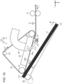
- the medium processing apparatus 11 includes a printing device 13 that performs recording on the medium 12, a post-processing apparatus 14 that performs post-processing on the recorded medium 12, and an intermediate device 15 located between the printing device 13 and the post-processing apparatus 14.
- the post-processing is a process performed accompanying a recording process, and the post-processing apparatus 14 of the present embodiment performs a stapler process of stapling a plurality of recorded media 12.
- a transport path 17 continuing from the printing device 13 via the intermediate device 15 to the post-processing apparatus 14 and indicated by a two-dot chain line in Fig. 1 is provided in the medium processing apparatus 11.
- the medium processing apparatus 11 includes at least one transport roller pair 19 that transports the medium 12 along the transport path 17 by driving the transport motor 18.
- the transport roller pair 19 may include a transport motor 18 in each of the intermediate device 15 and the post-processing apparatus 14.
- the printing device 13, the intermediate device 15, and the post-processing apparatus 14 may include a plurality of transport motors 18. Accordingly, operations of the plurality of transport roller pairs 19 in the printing device 13, the intermediate device 15, and the post-processing apparatus 14 can be controlled efficiently.
- the medium processing apparatus 11 is placed on a horizontal surface.
- the direction of gravity is indicated as a Z axis
- directions along a surface intersecting the Z axis are indicated as an X axis and a Y axis.
- the X axis, the Y axis, and the Z axis be perpendicular to each other, and the X axis and the Y axis are along the horizontal plane.
- an X axis direction is referred to as a width direction X
- a Z axis direction is referred to as a vertical direction Z
- a direction perpendicular to the width direction X and along the transport path 17 is referred to as a first transport direction Y1.
- the first transport direction Y1 is a direction in which the transport roller pair 19 transports the medium 12, and is a direction from the printing device 13 on an upstream side toward a post-processing apparatus 14 on a downstream side.
- Cassettes 21 that can accommodate the medium 12 in a stacked state are detachably provided in the printing device 13.
- the plurality of cassettes 21 may be detachably provided in the printing device 13.
- the printing device 13 includes a pickup roller 22 that sends the uppermost medium 12 among the medium 12 accommodated in the cassette 21 and a separation roller 23 that separates the medium 12 sent out by the pickup roller 22 one by one.
- the printing device 13 includes a support portion 25 that is provided at a position along the transport path 17 and supports the medium 12, and a recording head 27 that performs recording by ejecting a liquid from a nozzle 26 onto the medium 12 supported by the support portion 25.
- the recording head 27 is provided at a position facing the support portion 25 across the transport path 17.
- the recording head 27 may be a so-called line head capable of simultaneously ejecting a liquid along the width direction X or may be a so-called serial head that ejects a liquid while moving in the width direction X.
- the printing device 13 includes a discharge path 101 as a part of the transport path 17, through which the medium 12 is discharged, a switchback path 102 through which the medium 12 is switch-back-transported, and a reversing path 103 through which a posture of the medium 12 is reversed.
- the discharge path 101 is a path through which the medium 12 recorded by the recording head 27 is discharged toward a discharge portion 104.
- the discharge portion 104 is located at an upper portion of the printing device 13. The medium 12 transported along the discharge path 101 is placed on the discharge portion 104.
- the switchback path 102 and the reversing path 103 are paths through which the duplex printed medium 12 is transported.
- the switchback path 102 extends alongside the discharge path 101.
- the reversing path 103 extends from the switchback path 102.
- the reversing path 103 extends from a downstream side of the recording head 27 to an upstream side of the recording head 27 so as to pass above the recording head 27.
- the medium 12 When duplex printing is executed, the medium 12, one surface of which is printed, is first transported to the switchback path 102. Next, the medium 12 is switch-back-transported in the switchback path 102. That is, the medium 12 is transported in an opposite direction in the switchback path 102. Next, the medium 12 is transported from the switchback path 102 to the reversing path 103.
- the medium 12 in the switchback path 102 or the reversing path 103 As the medium in the switchback path 102 or the reversing path 103 is transported, the medium 12 is reversed from a posture in which the printed one surface faces the upper side to a posture in which the printed one surface faces the lower side.
- the medium 12 transported along the reversing path 103 is recorded again by the recording head 27.
- a surface of the medium 12, which is opposite to the already printed surface is printed.
- the printing device 13 executes duplex printing on the medium 12.
- the printing device 13 transports the printed medium 12 toward the discharge portion 104 or the intermediate device 15.
- the intermediate device 15 includes, as a part of the transport path 17, an introduction path 201, a first switchback path 202, a second switchback path 203, a first junction path 204, a second junction path 205, and a deviation path 206.
- the introduction path 201 is a path through which the medium 12 is introduced from the printing device 13.
- the first switchback path 202 and the second switchback path 203 are paths which extend from the introduction path 201 and through which the medium 12 is switch-back-transported.
- the first switchback path 202 and the second switchback path 203 extend to branch from the introduction path 201.
- the first junction path 204 is a path extending from the first switchback path 202.
- the second junction path 205 is a path extending from the second switchback path 203.
- the deviation path 206 is a path which extends from the first junction path 204 and the second junction path 205 and from which the medium 12 is derived toward the post-processing apparatus 14.
- the first junction path 204 and the second junction path 205 are joined to each other at the deviation path 206.
- the medium 12 transported from the printing device 13 to the intermediate device 15 is transported along the introduction path 201.
- the medium 12 transported along the introduction path 201 is transported toward the first switchback path 202 or the second switchback path 203.
- the medium 12 transported along the introduction path 201 is distributed to the first switchback path 202 or the second switchback path 203 by a flap or the like provided at a location branching from the introduction path 201 to the first switchback path 202 and the second switchback path 203.
- the medium 12 transported to the first switchback path 202 is switch-back-transported in the first switchback path 202.
- the medium 12 is transported to the first junction path 204.
- the medium 12 transported along the first junction path 204 is transported to the deviation path 206.
- the medium 12 transported from the introduction path 201 to the second switchback path 203 is switch-back-transported in the second switchback path 203.
- the medium 12 When being switch-back-transported in the second switchback path 203, the medium 12 is transported to the second junction path 205.
- the medium 12 transported along the second junction path 205 is transported to the deviation path 206.
- the medium 12 transported through the intermediate device 15 is switch-back-transported in the first switchback path 202 or the second switchback path 203. Therefore, the medium 12 transported through the intermediate device 15 is reversed from a posture in which a surface printed immediately before faces the upper side to a posture in which the surface printed immediately before faces the lower side, in the printing device 13. Accordingly, the medium 12 deviated by the post-processing apparatus 14 is in a posture in which the surface printed immediately before faces the lower side in the printing device 13.
- a drying time of the medium 12 to which a liquid is ejected is ensured. As the drying time of the medium 12 is ensured, transfer of the liquid discharged to the medium 12, curling of the medium 12 due to moisture of the discharged liquid, and the like can be suppressed.
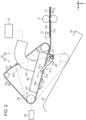
- the post-processing apparatus 14 includes a transport mechanism 30 that transports the medium 12 while the medium 12 is adsorbed onto a transport belt 29 and a detection unit 31 that detects the medium 12 located on an upstream side of the transport mechanism 30 in the first transport direction Y1 (see Fig.2 ).
- the post-processing apparatus 14 includes an intermediate stacker 32 as an example of a stacker for stacking the medium 12 transported by the transport belt 29.
- the post-processing apparatus 14 includes a post-processing mechanism 33 for post-processing the medium 12 stacked on the intermediate stacker 32 and a discharge stacker 34 on which the medium 12 sent out from the intermediate stacker 32 is stacked.
- the intermediate stacker 32 includes an alignment unit 36 that aligns the end of the stacked medium 12.
- the intermediate stacker 32 is obliquely provided such that an end thereof on the alignment unit 36 side is located on a lower side of an opposite end in a vertical direction Z.
- the transport mechanism 30 is provided such that the intermediate stacker 32 and the transport belt 29 face each other on an upper side of the intermediate stacker 32 in the vertical direction Z.
- the transport mechanism 30 includes a rotation mechanism 37 that rotates the transport belt 29 and an adsorption mechanism 38 that adsorbs the medium 12 recorded by the recording head 27 to the annular (looped or endless) transport belt 29.
- the rotation mechanism 37 includes a belt motor 40 that rotates the transport belt 29, a driving pulley 41 that rotates by driving of the belt motor 40, and a driven pulley 42 that is rotatable about an axial line that is parallel to an axial line of the driving pulley 41.
- the rotation mechanism 37 according to the present embodiment includes two driven pulleys 42.
- the transport belt 29 is hung and transported on a triangular ring including the driving pulley 41 and the driven pulleys 42.
- the transport belt 29 circulates outside the driving pulley 41 and the driven pulleys 42 by driving the belt motor 40.
- the rotation mechanism 37 rotates the transport belt 29 in a first rotation direction A1.
- the rotation mechanism 37 rotates the transport belt 29 in a second rotation direction A2 that is opposite to the first rotation direction A1.
- the transport mechanism 30 is provided rotatably about the driving pulley 41. That is, the transport belt 29 is provided to be displaceable between a contact position indicated by a two-dot chain line of Fig. 2 where the transport belt 29 comes into contact with the medium 12 stacked on the intermediate stacker 32 and a retraction position indicated by a solid line of Fig. 2 where the transport belt 29 is separated further from the intermediate stacker 32 than the contact position.
- the adsorption mechanism 38 includes the transport belt 29, an annular suction portion 45 having a suction chamber 44, and a fan 47 that sucks an inside of the suction chamber 44 via a duct 46.
- An outer surface of the transport belt 29 is an adsorption surface 29a that adsorbs the medium 12.
- the suction portion 45 is provided in a state of being in contact with or adjacent an inner surface 29b that is an inner surface of the transport belt 29 such that a part of the suction chamber 44 is covered by the transport belt 29.
- a plurality of transport belts 29 may be hung on the driving pulley 41 and the driven pulley 42 side by side in the width direction X.
- a large number of holes 49 passing through the transport belt 29 to open the adsorption surface 29a and the inner surface 29b are formed in the transport belt 29.
- a separate suction chamber 44 (or adsorption mechanism 38) may be provided for each transport belt 29, or one may be provided for two or more transport belts 29.
- the adsorption mechanism 38 causes an inside of the suction chamber 44 to have a negative pressure as the fan 47 is driven, and adsorbs the medium 12 to the adsorption surface 29a of the transport belt 29 through a hole 49 communicating with the suction chamber 44. That is, the adsorption mechanism 38 adsorbs the medium 12 to the transport belt 29 in a suction method of sucking air from the holes 49 formed in the transport belt 29.
- the transport mechanism 30 adsorbs the medium 12 to the transport belt 29, rotates the transport belt 29 in this state, and transports the medium 12 in a region between the transport belt 29 and the intermediate stacker 32.
- the rotation mechanism 37 rotates the transport belt 29, to which the medium 12 is adsorbed, in the first rotation direction A1, to transport the medium 12 in the first transport direction Y1.
- the rotation mechanism 37 rotates the transport belt 29, to which the medium 12 is adsorbed, in the second rotation direction A2, to transport the medium 12 in the second transport direction Y2 that is opposite to the first transport direction Y1.
- the rotation mechanism 37 transports the medium 12 in the second transport direction Y2 and stacks the medium 12 on the intermediate stacker 32.
- the post-processing apparatus 14 includes at least one separation flap 51 that detaches the medium 12 transported in the second transport direction Y2 from the transport belt 29, and an urging member 52, such as a torsion spring, that urges the separation flap 51.
- the post-processing apparatus 14 of the present embodiment includes eight separation flaps 51 arranged side by side at intervals in the width direction X.
- Each of the separation flaps 51 has a flap-upper surface 51a which is an example of a first flap surface and a flap-lower surface 51b which is an example of a second flap surface.
- the separation flap 51 interposed between the pair of transport belts 29 acts to separate the medium 12 from the transport belts 29 in common for all the medium 12 to be transported.
- the separation flap 51 not interposed between the pair of transport belts 29 acts to cause at least a pair of separation flaps 51 to come into contact with a side end portion of the medium 12 so as to separate the medium 12 from the transport belts 29. Accordingly, even when the media 12 having different sizes are transported, the media 12 can be properly separated from the transport belts 29. Therefore, it is preferable that a position of the separation flap 51 not interposed between the pair of transport belts 29 be determined according to a plurality of standard sizes of the medium 12 considered to be transported.
- the separation flap 51 swings about a flap shaft 53, and is provided such that a posture thereof can be changed.
- the separation flap 51 can be located at a first flap position indicated by a solid line of Fig. 2 and a second flap position indicated by a two-dot chain line of Fig. 2 .
- the urging member 52 urges the separation flap 51 toward the first flap position.
- the flap-upper surface 51a and the flap-lower surface 51b intersect the adsorption surface 29a of the transport belt 29 when viewed in the width direction X.
- an angle formed by the flap-upper surface 51a and the adsorption surface 29a is an acute angle
- an angle formed by the flap-lower surface 51b and the adsorption surface 29a is an obtuse angle.
- the medium processing apparatus 11 includes a controller 55 that comprehensively controls driving of mechanisms of the medium processing apparatus 11.
- the controller 55 includes a timekeeping unit 56 that measures a time.
- the controller 55 is connected to the detection unit 31 so as to receive a signal.
- the controller 55 transmits a signal to the transport motor 18, the recording head 27, the post-processing mechanism 33, the belt motor 40, and the fan 47, and controls operations of the mechanisms.
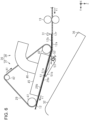
- the controller 55 drives the fan 47 in a state in which the transport belt 29 is positioned at the retraction position as indicated by the solid line of Fig. 2 , and drives the belt motor 40 in forward rotation to rotate the transport belt 29 in the first rotation direction A1.
- the adsorption mechanism 38 adsorbs an upper surface 12b as an example of a second surface of the medium 12.
- the upper surface 12b of the medium 12 is a surface that is opposite to a lower surface 12a as an example of a first surface of the medium 12 on the intermediate stacker 32 side. While being adsorbed to the transport belt 29, the medium 12 is transported in the first transport direction Y1 by the transport belt 29 that rotates in the first rotation direction A1.
- the front end 12f of the medium 12 which is an end on a downstream side in the first transport direction Y1 comes into contact with the flap-upper surface 51a to push the separation flap 51. Accordingly, the separation flap 51 rotates against an urging force of the urging member 52, and moves to the second flap position indicated by a two-dot chain line of Fig. 5 .
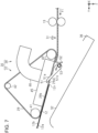
- the controller 55 drives the belt motor 40 in a reverse rotation after a predetermined time has elapsed. That is, when the rear end 12r is detected in a state which the belt motor 40 is driven in forward rotation, the controller 55 continues the forward rotation driving of the belt motor 40 for a predetermined time to rotate the transport belt 29 in the first rotation direction A1.
- the controller 55 temporarily stops driving of the belt motor 40 and continuously drives the belt motor 40 in the reverse direction to rotate the transport belt 29 in the second rotation direction A2.
- the predetermined time is a time required for the rear end 12r of the medium 12 to pass through the separation flap 51.
- the predetermined time is substantially equal to a quotient obtained by dividing a distance from the detection unit 31 to a tip end of the separation flap 51 along the transport path 17 by a speed at which the medium 12 is transported.
- the medium 12 is temporarily stopped in a state in which the rear end 12r is positioned on a downstream side of the separation flap 51 in the first transport direction Y1.
- the separation flap 51 returns to the first flap position by an urging force of the urging member 52. That is, when the rotation direction of the transport belt 29 is switched from the first rotation direction A1 to the second rotation direction A2, the separation flap 51 is located at the first flap position.
- the separation flap 51 is located at the first flap position, and at least a part of the flap-lower surface 51b comes into contact with the upper surface 12b of the medium 12 transported in the second transport direction Y2, and detaches the medium 12 from the adsorption surface 29a.
- the rear end 12r of the medium 12 detached from the adsorption surface 29a by the separation flap 51 comes into contact with the alignment unit 36 to be positioned, and the medium 12 is stacked on the intermediate stacker 32 positioned on a downstream side of the transport belt 29.
- the following medium 12 can be properly stacked on the intermediate stacker 32.
- the medium 12 is stacked such that the rear end 12r is aligned with the alignment unit 36 regardless of the size of the medium 12 in the first transport direction Y1.
- the post-processing mechanism 33 performs post-processing on the medium 12, and the controller 55 positions the transport belt 29 at the contact position.
- the controller 55 may perform the post-processing on the medium 12 in a state in which the transport belt 29 is in contact with the medium 12 stacked on the intermediate stacker 32 or may bring the transport belt 29 to the post-processed medium 12.
- the controller 55 drives the belt motor 40 in the forward rotation in a state in which the transport belt 29 is in contact with the post-processed medium 12. That is, after the post-processing mechanism 33 performs post-processing, the rotation mechanism 37 rotates the transport belt 29 located at the contact position in the first rotation direction A1.
- the medium 12 stacked on the intermediate stacker 32 is sent out from the intermediate stacker 32 in the first transport direction Y1, and is stacked on the discharge stacker 34.
- a configuration in which a medium is sent out from an intermediate stacker according to the second embodiment is different from that according to the first embodiment.
- the same configuration is designated by the same reference numeral, and duplicated description thereof will be omitted.
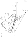
- the post-processing apparatus 14 may include a sending-out roller 58 that sends out the medium 12 stacked on the intermediate stacker 32.
- the sending-out roller 58 is provided to be displaceable between a contact position indicated by a solid line of Fig. 10 where the medium 12 stacked on the intermediate stacker 32 comes into contact with the transport belt 29 and a retraction position indicated by a two-dot chain line of Fig. 10 where the sending-out roller 58 is separated further from the transport belt 29 than the contact position.
- the controller 55 drives a not-illustrated movement mechanism to move the sending-out roller 58.
- the rotation mechanism 37 rotates the transport belt 29 in the first rotation direction A1 or the second rotation direction A2 to stack the medium 12 on the intermediate stacker 32, which is similar to the first embodiment.
- the controller 55 positions the sending-out roller 58 at the contact position to drive the belt motor 40 in the forward rotation. That is, the rotation mechanism 37 rotates the transport belt 29 in the first rotation direction A1 in a state in which the sending-out roller 58 is located at the contact position.
- the medium 12 stacked on the intermediate stacker 32 is sent out from the intermediate stacker 32 in the first transport direction Y1, and is stacked on the discharge stacker 34.
- the sending-out roller 58 is located at a contact position where the medium 12 stacked on the intermediate stacker 32 is in contact with the transport belt 29 and a retraction position where the medium 12 is separated further from the transport belt 29 than the contact position.
- the sending-out roller 58 located at the contact position sandwiches the medium between the sending out roller 58 and the transport belt 29. Therefore, when the transport belt 29 is rotated in the first rotation direction A1 in a state in which the sending-out roller 58 is located at the contact position, the medium 12 is sent out from the intermediate stacker 32 by the transport belt 29 and the sending-out roller 58.
- the downstream end of the transport belt 29 contacts the medium 12. However, the upstream end may contact it, as in the first embodiment, or both ends may contact it. Likewise, in the first embodiment the upstream end of the transport belt 29 may contact the medium 12, or both ends may contact it.
- the post-processing apparatus 14 may be configured so as to have a different urging member S2.
- the separation flap 51 may have a weight at a position that is opposite to a side of the flap shaft 53, which is in contact with the medium 12, and the separation flap 51 positioned at the second flap position may return to the first flap position by a weight thereof.
- the post-processing apparatus 14 may have, for example, a solenoid that moves the separation flap 51 and a driving source that moves the separation flap 51, such as a motor that rotates the flap shaft 53.
- the post-processing apparatus 14 may include a roller that interposes the medium 12 between the post-processing apparatus 14 and the transport belt 29 and is driven to rotate as the medium 12 is transported.
- the roller is a toothed roller having unevennesses formed on a peripheral surface thereof, a concern that the liquid adhering to the lower surface 12a of the duplex printed medium 12 is moved to the roller can be reduced.
- the post-processing apparatus 14 may include a presser that presses the medium 12 stacked on the intermediate stacker 32.
- the presser is configured with a plate-like elastic member rotatably provided or a weight displaceably provided. The presser presses the medium 12 stacked on the intermediate stacker 32 when the transport belt 29 rotates in the first rotation direction A1, and moves to a position separated from the medium 12 when the transport belt 29 rotates in the second rotation direction A2.
- the post-processing mechanism 33 may perform, as post-processing, a predetermined process such as a punch process of opening a hole in the medium 12, a shift process of moving and discharging the medium 12 in sheet units, a cutting process of cutting the medium 12, a signature process of folding the medium 12, a bookbinding process of bookbinding the medium 12, and a collating process.
- a predetermined process such as a punch process of opening a hole in the medium 12, a shift process of moving and discharging the medium 12 in sheet units, a cutting process of cutting the medium 12, a signature process of folding the medium 12, a bookbinding process of bookbinding the medium 12, and a collating process.
- the adsorption mechanism 38 may adsorb the medium 12 to the transport belt 29 by an electrostatic adsorption method in which the medium 12 and the transport belt 29 are charged.
- an angle between the flap-upper surface 51a and the adsorption surface 29a may be a right angle or an obtuse angle.
- an angle between the flap-lower surface 51b and the adsorption surface 29a may be a right angle or an obtuse angle.
- the separation flap 51 is located at the second flap position.
- the medium processing apparatus 11 may be an apparatus integrally having a function of the intermediate device 15, a function of the post-processing apparatus 14, and a function of the printing device 13.
- the medium processing apparatus 11 may be an apparatus including a device integrally having a function of the intermediate device 15 and a function of the post-processing apparatus 14 and the printing device 13.
- the medium processing apparatus 11 may be configured not to include the intermediate device 15 and the post-processing apparatus 14, and the transport mechanism 30 and a stacker on which the medium 12 transported by the transport mechanism 30 is stacked may be provided in the printing device 13.
- the medium processing apparatus 11 may be configured not to include the post-processing mechanism 33.
- the medium processing apparatus 11 may be stacked on the stacker of the printing device 13 such that the medium 12 recorded by the recording head 27 is transported in the first transport direction Y1 and the second transport direction Y2 by the transport mechanism 30 and the rear end 12r of the medium 12 is aligned.
- the liquid which is attached to the medium 12, can be selected in a predetermined manner as long as the liquid can be printed on the medium 12.
- the material is in a liquid phase state, and includes a fluid-state body such as liquid having high viscosity or low viscosity, sol, gel water, other inorganic solvents, an organic solvent, a solution, liquid resin, and liquid metal (metal melt).
- the state of the material includes a solution obtained by dissolving, dispersing, and mixing, in a solvent, particles of a functional material made of a solid such as a pigment or metal particles, in addition to the liquid.
- Representative examples of liquids include an ink.
- the ink includes various kinds of liquid compositions such as general water-based ink and oil-based ink, gel ink, hot melt ink and the like.
- the medium processing apparatus 11 is an apparatus that attaches a liquid such as an ink to the medium 12, and prints an image such as a letter, a picture, and a photograph, and may be a serial printer, a lateral printer, a page printer, and the like. Further, the printing device may be an offset printing device, a textile printing device, or the like.
Landscapes
- Engineering & Computer Science (AREA)
- Mechanical Engineering (AREA)
- Pile Receivers (AREA)
- Delivering By Means Of Belts And Rollers (AREA)
- Separation, Sorting, Adjustment, Or Bending Of Sheets To Be Conveyed (AREA)
- Sheets, Magazines, And Separation Thereof (AREA)
Claims (7)
- Medientransportvorrichtung (11), umfassend:einen Adsorptionsmechanismus (30), der eingerichtet ist, ein Medium (12) auf ein ringförmiges Transportband (29) zu adsorbieren;einen Rotationsmechanismus (40) zum Drehen des Transportbands (29)in einer ersten Drehrichtung (A1) oder einer zweiten Drehrichtung (A2), die der ersten Drehrichtung (A1) entgegengesetzt ist;einen ersten Stapler (32), auf dem das Medium (12), das von dem Transportband (29) transportiert wird, gestapelt werden kann;wobei der Adsorptionsmechanismus (30) eingerichtet ist, eine zweite Oberfläche (12b), die einer ersten Oberfläche (12a) des Mediums (12) gegenüberliegt, an der Seite des Staplers (32) zu adsorbieren;wobei nach Drehen des Transportbands (29), an das das Medium (12) adsorbiert ist, in der ersten Drehrichtung (A1) zum Transportieren des Mediums (12) in einer ersten Transportrichtung (Y1) der Rotationsmechanismus (37) eingerichtet ist, das Transportband (29) in der zweiten Drehrichtung (A2) zu drehen, um das Medium (12) in einer zweiten Transportrichtung (Y2) zu transportieren, um so das Medium (12) auf dem Stapler (32) zu stapeln;wobei die Medientransportvorrichtung (11) dadurch gekennzeichnet ist, dass sie weiter umfasst:eine Klappe (51), die einen Schwenkauflagepunkt (53) an einer stromaufwärts liegenden Seite in der ersten Transportrichtung (Y1) aufweist; und zwischen einer ersten Position, die eine Adsorptionsfläche (29a), an der das Medium (12) in dem Transportband (29) adsorbiert ist, nicht schneidet, wenn aus einer Breitenrichtung (X) betrachtet, die senkrecht zu der ersten Transportrichtung (Y1) ist, und einer zweiten Position, die die Adsorptionsfläche (29a) schneidet, schwenkbar ist; undein Presselement (52), das die Klappe (51) zu der zweiten Position presst,wobei die Klappe (51) enthälteine erste Klappenfläche (51a), die mit der ersten Oberfläche (12a) des Mediums (12) in Kontakt ist, das in der ersten Transportrichtung (Y1) transportiert wird, wenn sich die Klappe (51) in der ersten Position befindet, undeine zweite Klappenfläche (51b), die mit der zweiten Oberfläche (12b) des Mediums (12) in Kontakt ist, das in der zweiten Transportrichtung (Y2) transportiert wird, wenn sich die Klappe (51) in der zweiten Position befindet, undwobei, wenn eine Drehrichtung des Transportbands (29) von der ersten Drehrichtung (A1) zu der zweiten Drehrichtung (A2) umgeschaltet wird, die zweite Klappenfläche (51b) an der zweiten Position angeordnet ist und das Medium (12), das in der zweiten Transportrichtung (Y2) transportiert wird, von dem Transportband (29) gelöst wird.
- Medientransportvorrichtung nach Anspruch 1,
wobei ein Winkel zwischen der zweiten Klappenfläche (51b) und der Adsorptionsfläche (29a), wenn das Transportband (29) in der zweiten Drehrichtung (A2) dreht, ein stumpfer Winkel ist. - Medientransportvorrichtung nach einem der vorstehenden Ansprüche,
wobei der Adsorptionsmechanismus (30) eingerichtet ist, das Medium (12) an dem Transportband (29) durch ein Saugverfahren zum Ansaugen von Luft durch ein Loch (49), das in dem Transportband (29) gebildet ist, oder ein elektrostatisches Adsorptionsverfahren zum Laden des Mediums (12) und des Transportbands (29) zu adsorbieren. - Medientransportvorrichtung nach einem der vorstehenden Ansprüche,wobei der erste Stapler (32) eine Ausrichtungseinheit (36) zum Ausrichten eines Endes des Mediums (12) enthält undwobei ein Ende des ersten Staplers (32) an der Seite der Ausrichtungseinheit (36) an einer tieferen Seite in einer vertikalen Richtung liegt als ein entgegengesetztes Ende.
- Nachbearbeitungsvorrichtung, umfassend:die Medientransportvorrichtung nach einem der vorstehenden Ansprüche, wobei der erste Stapler (32) ein Zwischenstapler ist;einen Nachbearbeitungsmechanismus (33) zum Durchführen einer Nachbearbeitung an dem Medium (12) in dem Zwischenstapler (32); undeinen Entladestapler (34), auf dem das Medium (12), das von dem Zwischenstapler (32) ausgegeben wird, gestapelt werden kann.
- Nachbearbeitungsvorrichtung nach Anspruch 5,wobei das Transportband (29) zwischen einer Kontaktposition, an der das Transportband (29) mit dem Medium (12) in Kontakt ist, das auf dem Zwischenstapler (32) gestapelt ist, und einer Rückzugsposition, wo das Transportband (29) weiter weg von dem Zwischenstapler (32) getrennt ist als die Kontaktposition, verschiebbar ist, undwobei, nachdem der Nachbearbeitungsmechanismus (33) die Nachbearbeitung durchgeführt hat, der Rotationsmechanismus (37) eingerichtet ist, das Transportband (29), das sich an der Kontaktposition befindet, in der ersten Drehrichtung (A1) zu drehen.
- Nachbearbeitungsvorrichtung nach Anspruch 5 oder Anspruch 6, weiter umfassend:eine Ausgabewalze (58), die zwischen einer Kontaktposition, an der das Medium (12), das auf dem Zwischenstapler (32) gestapelt ist, mit dem Transportband (29) in Kontakt ist, und einer Rückzugsposition, wo das Medium (12) weiter weg von dem Transportband (29) getrennt ist als die Kontaktposition, verschiebbar ist,wobei der Rotationsmechanismus (37) eingerichtet ist, das Transportband (29) in der ersten Drehrichtung (A1) oder der zweiten Drehrichtung (A2) in einem Zustand zu drehen, in dem die Ausgabewalze (58) sich in der Rückzugsposition befindet, um das Medium (12) auf dem Zwischenstapler (32) zu stapeln, und nachdem der Nachbearbeitungsmechanismus (33) die Nachbearbeitung durchgeführt hat, das Transportband (29) in der ersten Drehrichtung (Y1) in einem Zustand dreht, in dem sich die Ausgabewalze (58) an der Kontaktposition befindet.
Applications Claiming Priority (1)
| Application Number | Priority Date | Filing Date | Title |
|---|---|---|---|
| JP2018069990A JP7069978B2 (ja) | 2018-03-30 | 2018-03-30 | 媒体処理装置 |
Publications (2)
| Publication Number | Publication Date |
|---|---|
| EP3546405A1 EP3546405A1 (de) | 2019-10-02 |
| EP3546405B1 true EP3546405B1 (de) | 2023-08-02 |
Family
ID=66041342
Family Applications (1)
| Application Number | Title | Priority Date | Filing Date |
|---|---|---|---|
| EP19166390.5A Active EP3546405B1 (de) | 2018-03-30 | 2019-03-29 | Medientransportvorrichtung und dazugehörige nachverarbeitungsvorrichtung |
Country Status (5)
| Country | Link |
|---|---|
| US (1) | US10807824B2 (de) |
| EP (1) | EP3546405B1 (de) |
| JP (1) | JP7069978B2 (de) |
| CN (1) | CN110316598B (de) |
| TW (1) | TWI686345B (de) |
Families Citing this family (4)
| Publication number | Priority date | Publication date | Assignee | Title |
|---|---|---|---|---|
| US11897279B2 (en) * | 2021-05-11 | 2024-02-13 | Ricoh Company, Ltd. | Envelope processing apparatus and image forming system |
| JP7647322B2 (ja) * | 2021-05-26 | 2025-03-18 | 株式会社リコー | 封入封緘装置及び画像形成システム |
| JP7767916B2 (ja) * | 2021-12-27 | 2025-11-12 | セイコーエプソン株式会社 | 記録システム |
| JP2023125775A (ja) * | 2022-02-28 | 2023-09-07 | 株式会社リコー | 封筒処理装置及び画像形成システム |
Family Cites Families (19)
| Publication number | Priority date | Publication date | Assignee | Title |
|---|---|---|---|---|
| FR1542578A (fr) * | 1966-07-16 | Carl Mueller K G Fa | Procédé et installation pour la manutention et le dépôt de matière en feuilles, notamment de feuilles de contreplaqué ou analogues | |
| JP2507333B2 (ja) | 1986-07-01 | 1996-06-12 | 株式会社アイジー技術研究所 | 縦目地構造 |
| DE69219868T2 (de) * | 1991-11-25 | 1998-01-02 | Sharp Kk | Vorrichtung zur Weiterverarbeitung nach der Kopierung |
| JP3507701B2 (ja) | 1998-05-22 | 2004-03-15 | 京セラミタ株式会社 | 給紙搬送装置 |
| JP3680062B2 (ja) | 2003-03-06 | 2005-08-10 | 株式会社東芝 | 紙葉類集積装置 |
| US7401772B2 (en) * | 2003-07-11 | 2008-07-22 | Nisca Corporation | Document feeder and image reading apparatus with the same |
| JP2005219829A (ja) * | 2004-02-03 | 2005-08-18 | Canon Inc | シート積載機構、シート後処理装置、及びそれらを備えた画像形成装置 |
| JP2006168890A (ja) * | 2004-12-14 | 2006-06-29 | Canon Inc | シート搬送装置および該装置を備えた画像形成装置 |
| JP4311756B2 (ja) * | 2006-09-06 | 2009-08-12 | キヤノン株式会社 | シート積載装置と画像形成装置 |
| CN101139053B (zh) * | 2006-09-06 | 2010-12-08 | 佳能株式会社 | 纸张堆叠装置和成像装置 |
| JP2008266020A (ja) | 2007-03-23 | 2008-11-06 | Fujifilm Corp | シート材集積装置及びシート材集積方法 |
| JP6315817B2 (ja) * | 2014-09-30 | 2018-04-25 | ホリゾン・インターナショナル株式会社 | 抜き加工された用紙の排出および集積装置 |
| WO2016199590A1 (ja) * | 2015-06-11 | 2016-12-15 | グラドコジャパン株式会社 | 用紙後処理装置 |
| JP6353419B2 (ja) | 2015-09-09 | 2018-07-04 | キヤノンファインテックニスカ株式会社 | シート搬送装置及びこれを備えた画像形成システム |
| JP6531709B2 (ja) * | 2016-04-27 | 2019-06-19 | 京セラドキュメントソリューションズ株式会社 | 画像形成装置 |
| JP6430439B2 (ja) * | 2016-06-07 | 2018-11-28 | 株式会社岩崎製作所 | フィルム剥離巻取り装置 |
| US10272698B2 (en) | 2016-07-13 | 2019-04-30 | Seiko Epson Corporation | Post processing device and printing system |
| US10399364B2 (en) | 2016-07-13 | 2019-09-03 | Seiko Epson Corporation | Intermediate unit, post processing device, and printing apparatus |
| JP2018008783A (ja) * | 2016-07-13 | 2018-01-18 | セイコーエプソン株式会社 | 記録後処理装置および記録装置 |
-
2018
- 2018-03-30 JP JP2018069990A patent/JP7069978B2/ja active Active
-
2019
- 2019-03-27 TW TW108110629A patent/TWI686345B/zh active
- 2019-03-27 US US16/366,017 patent/US10807824B2/en active Active
- 2019-03-28 CN CN201910245679.3A patent/CN110316598B/zh active Active
- 2019-03-29 EP EP19166390.5A patent/EP3546405B1/de active Active
Also Published As
| Publication number | Publication date |
|---|---|
| US10807824B2 (en) | 2020-10-20 |
| JP7069978B2 (ja) | 2022-05-18 |
| CN110316598B (zh) | 2021-07-23 |
| EP3546405A1 (de) | 2019-10-02 |
| CN110316598A (zh) | 2019-10-11 |
| TW201942041A (zh) | 2019-11-01 |
| TWI686345B (zh) | 2020-03-01 |
| JP2019178000A (ja) | 2019-10-17 |
| US20190299667A1 (en) | 2019-10-03 |
Similar Documents
| Publication | Publication Date | Title |
|---|---|---|
| JP7127716B2 (ja) | 印刷システム、印刷システムの制御方法 | |
| EP3546405B1 (de) | Medientransportvorrichtung und dazugehörige nachverarbeitungsvorrichtung | |
| JP6773196B2 (ja) | 媒体搬送ユニット、記録装置 | |
| US11180336B2 (en) | Medium transporting apparatus and post-processing apparatus | |
| JP2006213480A (ja) | 記録装置 | |
| US11325802B2 (en) | Sheet stacker and image forming system incorporating the sheet stacker | |
| CN111252612B (zh) | 介质输送装置及介质处理装置 | |
| US10155377B2 (en) | Medium transporting mechanism | |
| US11738965B2 (en) | Stacker and medium processing device | |
| JP4687031B2 (ja) | 記録装置 | |
| JP7310494B2 (ja) | 媒体搬送装置、処理装置、記録システム | |
| CN112520482A (zh) | 介质处理装置及记录装置 | |
| US10954091B2 (en) | Medium processing apparatus, post-processing apparatus, and medium transporting apparatus | |
| JP7147402B2 (ja) | 媒体処理装置、後処理装置、媒体搬送装置 | |
| US10526153B2 (en) | Printing apparatus | |
| JP7081275B2 (ja) | 媒体処理装置、後処理装置 | |
| JP2023105142A (ja) | 媒体積載装置 | |
| JP2020063123A (ja) | 媒体搬送装置、媒体処理装置及び後処理装置 | |
| KR20070030503A (ko) | 용지의 분리 적재 능력이 향상된 화상 형성기의 오프셋프린팅 장치 및 방법 |
Legal Events
| Date | Code | Title | Description |
|---|---|---|---|
| PUAI | Public reference made under article 153(3) epc to a published international application that has entered the european phase |
Free format text: ORIGINAL CODE: 0009012 |
|
| STAA | Information on the status of an ep patent application or granted ep patent |
Free format text: STATUS: THE APPLICATION HAS BEEN PUBLISHED |
|
| AK | Designated contracting states |
Kind code of ref document: A1 Designated state(s): AL AT BE BG CH CY CZ DE DK EE ES FI FR GB GR HR HU IE IS IT LI LT LU LV MC MK MT NL NO PL PT RO RS SE SI SK SM TR |
|
| AX | Request for extension of the european patent |
Extension state: BA ME |
|
| STAA | Information on the status of an ep patent application or granted ep patent |
Free format text: STATUS: REQUEST FOR EXAMINATION WAS MADE |
|
| 17P | Request for examination filed |
Effective date: 20200117 |
|
| RBV | Designated contracting states (corrected) |
Designated state(s): AL AT BE BG CH CY CZ DE DK EE ES FI FR GB GR HR HU IE IS IT LI LT LU LV MC MK MT NL NO PL PT RO RS SE SI SK SM TR |
|
| STAA | Information on the status of an ep patent application or granted ep patent |
Free format text: STATUS: EXAMINATION IS IN PROGRESS |
|
| 17Q | First examination report despatched |
Effective date: 20220429 |
|
| GRAP | Despatch of communication of intention to grant a patent |
Free format text: ORIGINAL CODE: EPIDOSNIGR1 |
|
| STAA | Information on the status of an ep patent application or granted ep patent |
Free format text: STATUS: GRANT OF PATENT IS INTENDED |
|
| INTG | Intention to grant announced |
Effective date: 20230321 |
|
| GRAS | Grant fee paid |
Free format text: ORIGINAL CODE: EPIDOSNIGR3 |
|
| GRAA | (expected) grant |
Free format text: ORIGINAL CODE: 0009210 |
|
| STAA | Information on the status of an ep patent application or granted ep patent |
Free format text: STATUS: THE PATENT HAS BEEN GRANTED |
|
| AK | Designated contracting states |
Kind code of ref document: B1 Designated state(s): AL AT BE BG CH CY CZ DE DK EE ES FI FR GB GR HR HU IE IS IT LI LT LU LV MC MK MT NL NO PL PT RO RS SE SI SK SM TR |
|
| REG | Reference to a national code |
Ref country code: GB Ref legal event code: FG4D |
|
| REG | Reference to a national code |
Ref country code: CH Ref legal event code: EP |
|
| REG | Reference to a national code |
Ref country code: DE Ref legal event code: R096 Ref document number: 602019033860 Country of ref document: DE |
|
| REG | Reference to a national code |
Ref country code: IE Ref legal event code: FG4D |
|
| REG | Reference to a national code |
Ref country code: LT Ref legal event code: MG9D |
|
| REG | Reference to a national code |
Ref country code: NL Ref legal event code: MP Effective date: 20230802 |
|
| REG | Reference to a national code |
Ref country code: AT Ref legal event code: MK05 Ref document number: 1594535 Country of ref document: AT Kind code of ref document: T Effective date: 20230802 |
|
| PG25 | Lapsed in a contracting state [announced via postgrant information from national office to epo] |
Ref country code: GR Free format text: LAPSE BECAUSE OF FAILURE TO SUBMIT A TRANSLATION OF THE DESCRIPTION OR TO PAY THE FEE WITHIN THE PRESCRIBED TIME-LIMIT Effective date: 20231103 |
|
| PG25 | Lapsed in a contracting state [announced via postgrant information from national office to epo] |
Ref country code: IS Free format text: LAPSE BECAUSE OF FAILURE TO SUBMIT A TRANSLATION OF THE DESCRIPTION OR TO PAY THE FEE WITHIN THE PRESCRIBED TIME-LIMIT Effective date: 20231202 |
|
| PG25 | Lapsed in a contracting state [announced via postgrant information from national office to epo] |
Ref country code: SE Free format text: LAPSE BECAUSE OF FAILURE TO SUBMIT A TRANSLATION OF THE DESCRIPTION OR TO PAY THE FEE WITHIN THE PRESCRIBED TIME-LIMIT Effective date: 20230802 Ref country code: RS Free format text: LAPSE BECAUSE OF FAILURE TO SUBMIT A TRANSLATION OF THE DESCRIPTION OR TO PAY THE FEE WITHIN THE PRESCRIBED TIME-LIMIT Effective date: 20230802 Ref country code: PT Free format text: LAPSE BECAUSE OF FAILURE TO SUBMIT A TRANSLATION OF THE DESCRIPTION OR TO PAY THE FEE WITHIN THE PRESCRIBED TIME-LIMIT Effective date: 20231204 Ref country code: NO Free format text: LAPSE BECAUSE OF FAILURE TO SUBMIT A TRANSLATION OF THE DESCRIPTION OR TO PAY THE FEE WITHIN THE PRESCRIBED TIME-LIMIT Effective date: 20231102 Ref country code: NL Free format text: LAPSE BECAUSE OF FAILURE TO SUBMIT A TRANSLATION OF THE DESCRIPTION OR TO PAY THE FEE WITHIN THE PRESCRIBED TIME-LIMIT Effective date: 20230802 Ref country code: LV Free format text: LAPSE BECAUSE OF FAILURE TO SUBMIT A TRANSLATION OF THE DESCRIPTION OR TO PAY THE FEE WITHIN THE PRESCRIBED TIME-LIMIT Effective date: 20230802 Ref country code: LT Free format text: LAPSE BECAUSE OF FAILURE TO SUBMIT A TRANSLATION OF THE DESCRIPTION OR TO PAY THE FEE WITHIN THE PRESCRIBED TIME-LIMIT Effective date: 20230802 Ref country code: IS Free format text: LAPSE BECAUSE OF FAILURE TO SUBMIT A TRANSLATION OF THE DESCRIPTION OR TO PAY THE FEE WITHIN THE PRESCRIBED TIME-LIMIT Effective date: 20231202 Ref country code: HR Free format text: LAPSE BECAUSE OF FAILURE TO SUBMIT A TRANSLATION OF THE DESCRIPTION OR TO PAY THE FEE WITHIN THE PRESCRIBED TIME-LIMIT Effective date: 20230802 Ref country code: GR Free format text: LAPSE BECAUSE OF FAILURE TO SUBMIT A TRANSLATION OF THE DESCRIPTION OR TO PAY THE FEE WITHIN THE PRESCRIBED TIME-LIMIT Effective date: 20231103 Ref country code: FI Free format text: LAPSE BECAUSE OF FAILURE TO SUBMIT A TRANSLATION OF THE DESCRIPTION OR TO PAY THE FEE WITHIN THE PRESCRIBED TIME-LIMIT Effective date: 20230802 Ref country code: AT Free format text: LAPSE BECAUSE OF FAILURE TO SUBMIT A TRANSLATION OF THE DESCRIPTION OR TO PAY THE FEE WITHIN THE PRESCRIBED TIME-LIMIT Effective date: 20230802 |
|
| PG25 | Lapsed in a contracting state [announced via postgrant information from national office to epo] |
Ref country code: PL Free format text: LAPSE BECAUSE OF FAILURE TO SUBMIT A TRANSLATION OF THE DESCRIPTION OR TO PAY THE FEE WITHIN THE PRESCRIBED TIME-LIMIT Effective date: 20230802 |
|
| PG25 | Lapsed in a contracting state [announced via postgrant information from national office to epo] |
Ref country code: ES Free format text: LAPSE BECAUSE OF FAILURE TO SUBMIT A TRANSLATION OF THE DESCRIPTION OR TO PAY THE FEE WITHIN THE PRESCRIBED TIME-LIMIT Effective date: 20230802 |
|
| PG25 | Lapsed in a contracting state [announced via postgrant information from national office to epo] |
Ref country code: SM Free format text: LAPSE BECAUSE OF FAILURE TO SUBMIT A TRANSLATION OF THE DESCRIPTION OR TO PAY THE FEE WITHIN THE PRESCRIBED TIME-LIMIT Effective date: 20230802 Ref country code: RO Free format text: LAPSE BECAUSE OF FAILURE TO SUBMIT A TRANSLATION OF THE DESCRIPTION OR TO PAY THE FEE WITHIN THE PRESCRIBED TIME-LIMIT Effective date: 20230802 Ref country code: ES Free format text: LAPSE BECAUSE OF FAILURE TO SUBMIT A TRANSLATION OF THE DESCRIPTION OR TO PAY THE FEE WITHIN THE PRESCRIBED TIME-LIMIT Effective date: 20230802 Ref country code: EE Free format text: LAPSE BECAUSE OF FAILURE TO SUBMIT A TRANSLATION OF THE DESCRIPTION OR TO PAY THE FEE WITHIN THE PRESCRIBED TIME-LIMIT Effective date: 20230802 Ref country code: DK Free format text: LAPSE BECAUSE OF FAILURE TO SUBMIT A TRANSLATION OF THE DESCRIPTION OR TO PAY THE FEE WITHIN THE PRESCRIBED TIME-LIMIT Effective date: 20230802 Ref country code: CZ Free format text: LAPSE BECAUSE OF FAILURE TO SUBMIT A TRANSLATION OF THE DESCRIPTION OR TO PAY THE FEE WITHIN THE PRESCRIBED TIME-LIMIT Effective date: 20230802 Ref country code: SK Free format text: LAPSE BECAUSE OF FAILURE TO SUBMIT A TRANSLATION OF THE DESCRIPTION OR TO PAY THE FEE WITHIN THE PRESCRIBED TIME-LIMIT Effective date: 20230802 |
|
| REG | Reference to a national code |
Ref country code: DE Ref legal event code: R097 Ref document number: 602019033860 Country of ref document: DE |
|
| PG25 | Lapsed in a contracting state [announced via postgrant information from national office to epo] |
Ref country code: IT Free format text: LAPSE BECAUSE OF FAILURE TO SUBMIT A TRANSLATION OF THE DESCRIPTION OR TO PAY THE FEE WITHIN THE PRESCRIBED TIME-LIMIT Effective date: 20230802 |
|
| PLBE | No opposition filed within time limit |
Free format text: ORIGINAL CODE: 0009261 |
|
| STAA | Information on the status of an ep patent application or granted ep patent |
Free format text: STATUS: NO OPPOSITION FILED WITHIN TIME LIMIT |
|
| 26N | No opposition filed |
Effective date: 20240503 |
|
| PG25 | Lapsed in a contracting state [announced via postgrant information from national office to epo] |
Ref country code: SI Free format text: LAPSE BECAUSE OF FAILURE TO SUBMIT A TRANSLATION OF THE DESCRIPTION OR TO PAY THE FEE WITHIN THE PRESCRIBED TIME-LIMIT Effective date: 20230802 |
|
| REG | Reference to a national code |
Ref country code: CH Ref legal event code: PL |
|
| PG25 | Lapsed in a contracting state [announced via postgrant information from national office to epo] |
Ref country code: BG Free format text: LAPSE BECAUSE OF FAILURE TO SUBMIT A TRANSLATION OF THE DESCRIPTION OR TO PAY THE FEE WITHIN THE PRESCRIBED TIME-LIMIT Effective date: 20230802 |
|
| PG25 | Lapsed in a contracting state [announced via postgrant information from national office to epo] |
Ref country code: LU Free format text: LAPSE BECAUSE OF NON-PAYMENT OF DUE FEES Effective date: 20240329 |
|
| PG25 | Lapsed in a contracting state [announced via postgrant information from national office to epo] |
Ref country code: MC Free format text: LAPSE BECAUSE OF FAILURE TO SUBMIT A TRANSLATION OF THE DESCRIPTION OR TO PAY THE FEE WITHIN THE PRESCRIBED TIME-LIMIT Effective date: 20230802 |
|
| PG25 | Lapsed in a contracting state [announced via postgrant information from national office to epo] |
Ref country code: MC Free format text: LAPSE BECAUSE OF FAILURE TO SUBMIT A TRANSLATION OF THE DESCRIPTION OR TO PAY THE FEE WITHIN THE PRESCRIBED TIME-LIMIT Effective date: 20230802 Ref country code: LU Free format text: LAPSE BECAUSE OF NON-PAYMENT OF DUE FEES Effective date: 20240329 Ref country code: BG Free format text: LAPSE BECAUSE OF FAILURE TO SUBMIT A TRANSLATION OF THE DESCRIPTION OR TO PAY THE FEE WITHIN THE PRESCRIBED TIME-LIMIT Effective date: 20230802 |
|
| REG | Reference to a national code |
Ref country code: BE Ref legal event code: MM Effective date: 20240331 |
|
| PG25 | Lapsed in a contracting state [announced via postgrant information from national office to epo] |
Ref country code: BE Free format text: LAPSE BECAUSE OF NON-PAYMENT OF DUE FEES Effective date: 20240331 |
|
| PG25 | Lapsed in a contracting state [announced via postgrant information from national office to epo] |
Ref country code: IE Free format text: LAPSE BECAUSE OF NON-PAYMENT OF DUE FEES Effective date: 20240329 |
|
| PG25 | Lapsed in a contracting state [announced via postgrant information from national office to epo] |
Ref country code: IE Free format text: LAPSE BECAUSE OF NON-PAYMENT OF DUE FEES Effective date: 20240329 Ref country code: BE Free format text: LAPSE BECAUSE OF NON-PAYMENT OF DUE FEES Effective date: 20240331 Ref country code: CH Free format text: LAPSE BECAUSE OF NON-PAYMENT OF DUE FEES Effective date: 20240331 |
|
| PGFP | Annual fee paid to national office [announced via postgrant information from national office to epo] |
Ref country code: DE Payment date: 20250319 Year of fee payment: 7 |
|
| PGFP | Annual fee paid to national office [announced via postgrant information from national office to epo] |
Ref country code: FR Payment date: 20250326 Year of fee payment: 7 |
|
| PGFP | Annual fee paid to national office [announced via postgrant information from national office to epo] |
Ref country code: GB Payment date: 20250324 Year of fee payment: 7 |
|
| PG25 | Lapsed in a contracting state [announced via postgrant information from national office to epo] |
Ref country code: CY Free format text: LAPSE BECAUSE OF FAILURE TO SUBMIT A TRANSLATION OF THE DESCRIPTION OR TO PAY THE FEE WITHIN THE PRESCRIBED TIME-LIMIT; INVALID AB INITIO Effective date: 20190329 |
|
| PG25 | Lapsed in a contracting state [announced via postgrant information from national office to epo] |
Ref country code: HU Free format text: LAPSE BECAUSE OF FAILURE TO SUBMIT A TRANSLATION OF THE DESCRIPTION OR TO PAY THE FEE WITHIN THE PRESCRIBED TIME-LIMIT; INVALID AB INITIO Effective date: 20190329 |
|
| PG25 | Lapsed in a contracting state [announced via postgrant information from national office to epo] |
Ref country code: TR Free format text: LAPSE BECAUSE OF FAILURE TO SUBMIT A TRANSLATION OF THE DESCRIPTION OR TO PAY THE FEE WITHIN THE PRESCRIBED TIME-LIMIT Effective date: 20230802 |