EP3544467B1 - Schubkasten - Google Patents
Schubkasten Download PDFInfo
- Publication number
- EP3544467B1 EP3544467B1 EP17800543.5A EP17800543A EP3544467B1 EP 3544467 B1 EP3544467 B1 EP 3544467B1 EP 17800543 A EP17800543 A EP 17800543A EP 3544467 B1 EP3544467 B1 EP 3544467B1
- Authority
- EP
- European Patent Office
- Prior art keywords
- drawer according
- drawer
- side frame
- shaped
- molded part
- Prior art date
- Legal status (The legal status is an assumption and is not a legal conclusion. Google has not performed a legal analysis and makes no representation as to the accuracy of the status listed.)
- Active
Links
Images












Classifications
-
- A—HUMAN NECESSITIES
- A47—FURNITURE; DOMESTIC ARTICLES OR APPLIANCES; COFFEE MILLS; SPICE MILLS; SUCTION CLEANERS IN GENERAL
- A47B—TABLES; DESKS; OFFICE FURNITURE; CABINETS; DRAWERS; GENERAL DETAILS OF FURNITURE
- A47B88/00—Drawers for tables, cabinets or like furniture; Guides for drawers
- A47B88/90—Constructional details of drawers
- A47B88/941—Drawers being constructed from two or more parts
-
- A—HUMAN NECESSITIES
- A47—FURNITURE; DOMESTIC ARTICLES OR APPLIANCES; COFFEE MILLS; SPICE MILLS; SUCTION CLEANERS IN GENERAL
- A47B—TABLES; DESKS; OFFICE FURNITURE; CABINETS; DRAWERS; GENERAL DETAILS OF FURNITURE
- A47B88/00—Drawers for tables, cabinets or like furniture; Guides for drawers
- A47B88/90—Constructional details of drawers
-
- A—HUMAN NECESSITIES
- A47—FURNITURE; DOMESTIC ARTICLES OR APPLIANCES; COFFEE MILLS; SPICE MILLS; SUCTION CLEANERS IN GENERAL
- A47B—TABLES; DESKS; OFFICE FURNITURE; CABINETS; DRAWERS; GENERAL DETAILS OF FURNITURE
- A47B88/00—Drawers for tables, cabinets or like furniture; Guides for drawers
- A47B88/90—Constructional details of drawers
- A47B88/919—Accessories or additional elements for drawers, e.g. drawer lighting
-
- F—MECHANICAL ENGINEERING; LIGHTING; HEATING; WEAPONS; BLASTING
- F16—ENGINEERING ELEMENTS AND UNITS; GENERAL MEASURES FOR PRODUCING AND MAINTAINING EFFECTIVE FUNCTIONING OF MACHINES OR INSTALLATIONS; THERMAL INSULATION IN GENERAL
- F16B—DEVICES FOR FASTENING OR SECURING CONSTRUCTIONAL ELEMENTS OR MACHINE PARTS TOGETHER, e.g. NAILS, BOLTS, CIRCLIPS, CLAMPS, CLIPS OR WEDGES; JOINTS OR JOINTING
- F16B12/00—Jointing of furniture or the like, e.g. hidden from exterior
- F16B12/10—Jointing of furniture or the like, e.g. hidden from exterior using pegs, bolts, tenons, clamps, clips, or the like
- F16B12/12—Jointing of furniture or the like, e.g. hidden from exterior using pegs, bolts, tenons, clamps, clips, or the like for non-metal furniture parts, e.g. made of wood, of plastics
-
- F—MECHANICAL ENGINEERING; LIGHTING; HEATING; WEAPONS; BLASTING
- F16—ENGINEERING ELEMENTS AND UNITS; GENERAL MEASURES FOR PRODUCING AND MAINTAINING EFFECTIVE FUNCTIONING OF MACHINES OR INSTALLATIONS; THERMAL INSULATION IN GENERAL
- F16B—DEVICES FOR FASTENING OR SECURING CONSTRUCTIONAL ELEMENTS OR MACHINE PARTS TOGETHER, e.g. NAILS, BOLTS, CIRCLIPS, CLAMPS, CLIPS OR WEDGES; JOINTS OR JOINTING
- F16B12/00—Jointing of furniture or the like, e.g. hidden from exterior
- F16B12/10—Jointing of furniture or the like, e.g. hidden from exterior using pegs, bolts, tenons, clamps, clips, or the like
- F16B12/28—Jointing of furniture or the like, e.g. hidden from exterior using pegs, bolts, tenons, clamps, clips, or the like for metal furniture parts
-
- A—HUMAN NECESSITIES
- A47—FURNITURE; DOMESTIC ARTICLES OR APPLIANCES; COFFEE MILLS; SPICE MILLS; SUCTION CLEANERS IN GENERAL
- A47B—TABLES; DESKS; OFFICE FURNITURE; CABINETS; DRAWERS; GENERAL DETAILS OF FURNITURE
- A47B2210/00—General construction of drawers, guides and guide devices
- A47B2210/02—Drawers with hollow lateral walls in two parts
-
- A—HUMAN NECESSITIES
- A47—FURNITURE; DOMESTIC ARTICLES OR APPLIANCES; COFFEE MILLS; SPICE MILLS; SUCTION CLEANERS IN GENERAL
- A47B—TABLES; DESKS; OFFICE FURNITURE; CABINETS; DRAWERS; GENERAL DETAILS OF FURNITURE
- A47B2220/00—General furniture construction, e.g. fittings
- A47B2220/0075—Lighting
- A47B2220/0077—Lighting for furniture, e.g. cupboards and racks
Definitions
- the present invention relates to a drawer according to the preamble of claim 1.
- the DE 10 2014 000 822 A1 discloses a method for producing a frame of a drawer, in which a plastic material is extruded into a profile strand and cut off and then covered with a film.
- the extrusion can strengthen the outer film, but the side frame produced in this way cannot be fixed to a front panel or a rear wall of a drawer.
- extrusion profiles can only be produced with the same cross-section, which limits the functionality of the shaping.
- the EP 865 745 discloses a drawer with a double-walled drawer frame, in which profile parts made of plastic are received, which stiffen the drawer frame.
- WO 2008/028811 discloses a drawer in which the side frames are held via adapters which are arranged in the side frames and connect them to a bottom of the drawer.
- At least one side frame preferably both side frames, has a thin-walled casing which is supported by an inner core, the inner core having at least two molded parts which are positively held together.
- the use of at least two molded parts enables greater flexibility with regard to the shape of the core than in the extrusion process, so that the connection of the front panel and / or rear wall is facilitated.
- the stable construction of the side frame can be ensured by the form-fitting arrangement of the at least two molded parts.
- the inner core preferably has at least three molded parts which are held together in a form-fitting manner. At least three different molded parts can be provided, which are not designed to be identical.
- the molded parts preferably extend over the entire length of the envelope, so that the envelope is well supported.
- a first molded part is provided with fastening means for fixing the front panel.
- the front panel can, for example, have openings into each of which a pin is inserted.
- Other fastening means for the front panel for example screw connections, can also be provided.
- a second molded part preferably has fastening means for the rear wall.
- the second molded part can, for example, be angular and form a contact surface for the rear wall with a web.
- One or more third molded parts which connect the first molded part to the second molded part, can then be provided between the first molded part and the second molded part.
- the number of molded parts can largely be chosen freely, depending on the length of the drawer.
- the molded parts can be produced cost-effectively as injection molded parts that can be plugged into one another, for example, via tongue and groove connections.
- the envelope For a stable fixation of the envelope, it can be glued to the molded parts.
- the molded parts can be essentially plate-shaped and have a laterally protruding web as a support for the floor.
- the cover does not have to be designed to be closed, but can have an opening for the passage of the base, which engages in the cover at the edge.
- the casing is preferably formed from one or more metal sheets.
- the thickness of the metal sheets can be less than 0.8 mm, in particular less than 0.5 mm.
- the molded parts are preferably made of plastic, wherein a dimensionally stable material, in particular made of metal or plastic, can be provided for reinforcement, which is fixed on or in the molded parts.
- a dimensionally stable material in particular made of metal or plastic
- the entire side frame can have a thickness of less than 10 mm, in particular less than 8 mm.
- the casing can also have individual elements made of other materials, for example wood, in order to be designed in a visually appealing manner.
- the casing can preferably be assembled without welding, in particular only by gluing the bent metal sheets.
- the side frame forms a smaller sound body than a hollow profile, so that noises when moving the drawer are also muffled.
- the functionality of the side frame can be improved if the inner core is formed with molded parts from different heights in a vertical orientation to the longitudinal direction of the side frame.
- the free spaces resulting from the different heights of the molded parts in the inner core can be filled, for example, by at least one wall element made of glass or another optically appealing material, for example colored, transparent or translucent glass, wood or natural stone.
- a light guide or light source preferably LED, on or in the molded parts of the side frame.
- a groove for receiving a bottom of the drawer is formed on at least one molded part.
- a receptacle with a claw made of metallic material can be provided in the groove for fixing the floor.
- the floor can then be fixed in a force-locking manner by being pushed into the groove, the claw preferably digging into the floor on an underside of the floor.
- a molded part arranged at the end, which is arranged adjacent to the front panel or the rear wall, comprises a receptacle into which a fastening element for fixing the front panel or the rear wall is inserted.
- the fastening element can be mounted displaceably or pivotably relative to the molded part via an adjusting mechanism, so that the front panel or the rear wall can be aligned by adjusting the fastening element.
- the adjustment mechanism can be used for depth adjustment or tilt adjustment as well as for height or side adjustment. The insertion of the fastening element can depend on the installation situation, so that a different functionality is obtained with one and the same molded part depending on the use of a fastening element.
- a drawer 1 in particular for a piece of furniture or a household appliance, comprises a base 2, from which a rear wall 3 protrudes at the rear and is connected to two side frames 10 on opposite sides.
- the side frames 10 connect the rear wall 3 to a plate-shaped front panel, not shown, which covers a front side of the drawer 1.
- the front panel is fixed to pins 23 that protrude from the side frames 10, which can be inserted into corresponding openings on the front panel and optionally glued.
- Each side frame 10 comprises a casing made from two metal sheets 11 and 12, which surround an inner cavity which is filled by a core 20.
- the core 20 is formed from a plurality of molded parts 21, 24 and 30 which are held together in a form-fitting manner.
- a first molded part 21 is used to fix the front panel and comprises two protruding pins 23 on one end face.
- the molded part 21 is essentially plate-shaped and has an inwardly protruding web 22 for supporting the base 2.
- the molded part 24 also has an inwardly directed web 25 for supporting the base 2.
- a further molded part 30 is provided on the rear, which is angular and has a web 31 which is aligned parallel to the plane of the rear wall 3.
- the web 31 engages around the rear wall 3 and can be connected to it, for example by means of screws.
- the molded part 30 has a further section which is aligned with the adjacent molded parts 24.
- a plurality of middle molded parts 24 with the same shape are arranged, for example between two and eight molded parts, depending on the length of the side frame 10.
- the casing comprises a first thin-walled metal sheet 11 and a second thin-walled metal sheet 12, which can have a thickness of less than 0.8 mm, in particular less than 0.5 mm, for example between 0.3 mm and 0.5 mm.
- the metal sheet 12 has an upper edge 13 which is connected to a web 17 which is angled downwards so that a U-shaped upper edge is bent. In the lower area, the otherwise plate-shaped sheet metal 12 is provided with an angled portion 14.
- the sheet metal 11 is essentially plate-shaped and comprises a step 16 in the upper region, which is adjoined by a web 15 which extends parallel to the sheet metal 11.
- the side frame 10 can be assembled in such a way that the core 20 is first assembled and then the sheet metal 12 is glued to the core 20. Furthermore, the metal sheet 11 is inserted into the space between the web 17 and a wall of the core 20, and the metal sheet 11 is also glued to the core 20. The unit thus formed can then with the rear wall 3, the front panel and the bottom 2 are assembled to form a drawer. To assemble the rear wall, openings 32 are cut out in the web 31, into which screws can be screwed.
- a groove-shaped receptacle 28 is formed on the molded parts 21, 24 and 30 next to the webs 22, into which a side edge of the base 2 can be inserted so that it is also secured against lifting.
- the sheathing with the metal sheets 11 and 12 does not completely surround the core 20, but rather a partial area for the base 2 and an area below the webs 22 is not enveloped, since this is usually not visible.
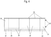
- FIG 4 an assembled core from the molded parts 21, 24 and 30 is shown.
- the molded parts 21, 24 and 30 form a recess 19 on an upper edge into which the upper web 15 with the step 16 of the metal sheet 11 can be inserted, so that the metal sheet 11 is also fixed to the core 20 in a form-fitting manner.
- FIG. 5 a further embodiment of a side frame is shown, which is similar to FIG Figure 2 is formed, but the molded parts 21, 24 and 30 have one or more openings for reinforcing elements 40 and 41.
- a first band or strip-shaped reinforcing element 40 for example made of sheet steel or a hard plastic, extends through the central molded parts 24 and has a projection 42 or a recess with a pin or bolt inserted therein, which extends into an opening 43 of the front molded part 21 and an opening 33 of the rear molding 30 is insertable.
- the band-shaped reinforcing element 40 can increase the lateral stability and the resilience of the core in tension.
- a rod-shaped reinforcing element 41 is passed through openings 29 in the molded parts 21, 24 and 30, which, for example, is glued in the openings 29. Other mechanical fixings for the reinforcement part 41 can also be provided.
- FIGS Figures 7A through 7F different variants for a sheathing of a core 20 are shown, which is only shown schematically and can be designed as shown in FIGS Figures 2 or 5 is shown.
- FIG 7A a plate-shaped metal sheet 11 'according to the invention is shown, which is glued to the core 20, and a second metal sheet 12' is bent in a U-shape in the upper region and is also glued to the core 20.
- the step 16 on the sheet metal and the bend 14 on the sheet metal have been omitted.
- the in Figure 7B The embodiment shown, not according to the invention, is formed from three parts, namely two plate-shaped metal sheets 50 and 51, which are covered in the upper area by a U-shaped profile 52, which overlaps the outer walls of the metal sheets 50 and 51 with the two legs.
- FIG. 7C a variant is shown in which the core 20 is covered by a one-piece sheath 55 which is bent in accordance with the core, a recess for the passage of the base 2 being omitted.
- the casing is formed by two metal sheets 60 and 61, which are plate-shaped on the inside and outside and are bent in a U-shape in the upper area, the leg engaging in a groove-shaped receptacle in the core 20 in the connecting area.
- the stability of the unit made up of sheath and core 20 can be increased, especially if the legs engaging in core 20 are also glued to core 20.
- Sheath 70 is again formed in one piece, similar to FIG Figure 7C , however, a bend 71 is provided above the drawer 1, which rests on the base 2 so that no gap is visible between the top of the base 2 and the envelope.
- the Figure 7F shows an embodiment of a casing with an inner wall 80 and an outer wall 81 made of angled metal sheets which surround a core 20.
- an insert part 82 is provided which can be inserted into a receptacle on the core 20 with a latching element 83, in particular a pin with a latching head.
- a latching element 83 in particular a pin with a latching head.
- the inner wall and the outer wall 81 can be fixed in the manner of a welt.
- the inner wall 80 and the outer wall 81 at least partially engage with one end portion in the receptacle on the core 20 and are fixed by the plug-in part 82 in a form-fitting or force-fitting manner.
- the core 20 can have only one reinforcement element 40 or 41 or more than the reinforcement elements 40 and 41 shown.
- the reinforcement does not have to extend through the molded parts, but can also be fixed to a surface of the molded parts, for example by gluing.
- the molded parts 21, 24 and 30 are held together in a form-fitting manner via tongue and groove connections. It is of course also possible to provide other form-fitting connections, for example dovetail connections, hook connections or other plug-in or pivot connections.
- the molded parts 21, 24 and 30 are made of plastic by injection molding. Depending on the length of the side frame, more or less central molded parts 24 can be inserted between the molded part 21 and the rear molded part 30.
- FIG. 8A to 8C Another embodiment of a side frame 10 ′ is shown, which has a front molded part 90, a central molded part 91 and a rear molded part 92.
- the middle molded part 91 has a smaller height in the vertical longitudinal direction of the side frame than the molded parts 90 and 92.
- a wall element made of glass or another visually appealing material is placed on the middle molded part and remains visible from the outside.
- an inner casing is provided on the inside of the side frame, which has a front web 93 and a rear web 95, between which a recess 94 is formed, in which the wall element made of glass remains visible.
- the front molded part 90 and the rear molded part 92 are connected to one another via the central molded part 91, on which a groove is provided for receiving a base for the drawer.
- the web 93 covers the front molded part 90 and protrudes over it in the longitudinal direction of the frame, so that the wall element made of glass is partially covered by the web 93 and the rear web 95 and thereby the wall element 112 is held in the vertical direction to the longitudinal direction of the side frame.
- an outer casing 100 with two webs 103 and 104 is provided on the outside of the frame, which optionally also with webs 93 and 95 are connected, wherein a U-shaped edge 101 is formed on the front web 103, which overlaps an upper side of the molded part 90.
- an end section of the wall element 112 is overlapped so that the wall element 91 is held by the sheaths.
- the front molded part 90 and the rear molded part 92 are arranged in one plane with the wall element made of glass and form almost flat contact surfaces in the direction of the inner and outer casing.
- a groove 96 is formed on the upper side of the molded parts 90 and 92 and can be used for the assembly of further components, for example cover strips or attachment frames. In the embodiment of Figures 8 and 9 however, the groove 96 is not occupied.
- the molded part 90 is provided for assembly, before the inner casing with the web 93 and the outer casing 100 with the U-shaped edge 101 are fitted.
- a step-shaped edge 98 is formed, which engages in a corresponding receptacle 97 on the molded part 90, so that the inner casing with the web 93 is held in a form-fitting manner on the molded part 90.
- the stepped edge 98 is then covered by the U-shaped edge 101 of the outer casing 100, it being possible for the casings to optionally also be glued to one another.
- FIG. 10A and 10B a modified embodiment of a side frame is shown in which an inner casing 93 'has no recess 94, and a plurality of molded parts 90 are provided inside, as has already been explained above.
- an outer casing 100 is provided which, with a U-shaped edge 101, surrounds the molded parts 90 on an upper side.
- a groove 96 is recessed in the molded parts 90, into which a light guide 105 is inserted.
- Light is radiated into the light guide 105, for example via an LED which is arranged in the side frame, the rear wall or the front panel.
- Several openings 102 are recessed in the U-shaped edge 101 so that light can be emitted via the light guide 105 through the openings 102, which results in a visually appealing effect.
- FIG 11A and 11B is an opposite Figure 10 A modified exemplary embodiment is shown in which an insertion part 110 is inserted into the groove 96 on the molded parts 90, on the top of which a light guide 105 is arranged.
- the rod-shaped light guide 105 remains visible from the outside after assembly can serve to distribute light which is radiated into an end face of the light guide 105.
- the inner sheath 93 ′ extends to just below the light guide 105, and the outer sheath does not cover the light guide 105 either.
- the inner cover 93 ' may have a curved edge 98' at the top and the outer cover may have a curved edge 101 which are inserted between a top of the molding and a thickened head portion of the male part 110.
- the sheaths 93 'and 100' can thus be held in position via the plug-in part 110.
- the insertion part 110 has a thickened foot section 111 which is inserted into a corresponding widening of the groove 96.
- the light guide 105 is fixed, in particular glued or clamped, to the top of the plug-in part 110.
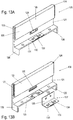
- FIG. 13A and 13B a modified molded part made of plastic for a side frame is shown, wherein the metallic casing has been omitted.
- the side frame comprises at least one molded part 120 with a groove 121 for receiving a bottom of the drawer.
- the molded parts 120 preferably extend over the entire length of the side frame.
- a wall element 122 is provided above the Nur, which has a groove 123 in the longitudinal direction of the side frame on one end face, into which a protruding tongue 124 of an adjacent molded part 120 can be inserted.
- several molded parts 120 can be inserted into one another in a form-fitting manner over the entire length of a side frame.
- An opening 125 which is used to fix a metal bracket 127, is provided in a bottom of the groove 121.
- the metal bracket 127 comprises a vertical leg 128 with mounting openings 129 which are arranged within the opening 125 in the installed position.
- a receptacle is formed, into which a second leg 130 of the metal bracket 127 is inserted.
- a claw 133 with upwardly projecting teeth is formed on the second leg 130 and is surrounded by two webs with assembly openings 134.
- the bottom of the drawer can be pushed into the groove at the edge and fixed in a force-locking manner, the claw 133 digging into the bottom on an underside of the bottom.
- the clamping forces on the claw 133 are then distributed over the horizontal leg 131, which can be supported at opposite ends by webs 126 protruding downwards.
- the top of the second leg 130 and the top of the horizontal leg 131 can be aligned essentially flush to support the floor.
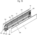
- the side frame 10 ' comprises a casing which is made of two bent metal sheets 11' and 12 'and surrounds an inner core which comprises one or more central molded parts 201, an end molded part 202 facing the front panel and an end molded part 220 facing the rear wall .
- the central molded parts 201 can be produced from plastic in an injection molding process and comprise a lattice structure, so that, based on the volume of the molded part 201, only a little material is required.
- a groove 209 for inserting an edge of a bottom of the drawer is formed on the molded parts 201, 202 and 220 under the metal sheet 12 '.
- molded parts 201, 202 and 220 On the upper side of the molded parts 201, 202 and 220 are a plurality of upwardly projecting webs 219, on which the two metal sheets 11 'and 12' of the casing can be fixed, whereby the type of fastening can also be configured according to one of the preceding exemplary embodiments .
- the molded part 202 facing the front panel is provided with a recess or receptacle into which a fastening element 203 is inserted.
- the fastening element 203 is surrounded by the molded part 202 on at least three sides, preferably on at least four sides.
- the fastening element 203 comprises an adjustment element 204 which is adjustable relative to the fastening element 203.
- Fastening means 205 for fixing the front panel are provided on the adjustment element 204, the fastening means 205 in the illustrated embodiment being designed as pins which are inserted into corresponding bores or openings on the front panel.
- a height adjustment is provided on the molded part 202, whereby a mounting part 207 can be fixed in the lower region of the molded part 202, on which a curved guide is formed which interacts with a lever 206 which, when rotated, adjusts the position of the front panel relative to the floor can.
- the molded part 202 arranged adjacent to the front panel can be constructed identically to a molded part arranged on the opposite side frame that faces the rear wall.
- the one facing the flashback Molded part 220 on the same side frame is designed with mirror symmetry to a central plane perpendicular to the longitudinal direction of the side frame.
- a modified fastening element 221 is inserted into the receptacle, which is held essentially positively on the molded part 220 and serves to fix the side frame to the rear wall.
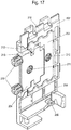
- FIG 17 the molding 202 adjacent to the front panel is shown with the fastening element 203 in detail.
- a rotatable eccentric 210 is located on the fastening element 203, which is inserted in an opening 214 on a wall section of the molded part 202 ( Figure 18 ) is rotatably mounted.
- the adjusting element 204 can be adjusted in height relative to the fastening element 203 via the eccentric 210.
- the adjusting element 204 is accommodated with vertical play within the fastening element 203, with one or more webs 212 being formed on the fastening element 203 for guidance which engage in corresponding recesses 213 or guide receptacles.
- a lateral adjustment 211 which is arranged on the adjusting element 204, is also provided on the fastening element 203.
- the position of the adjusting element 204 can be changed in a direction horizontally and perpendicular to the longitudinal direction of the side frame via the side adjustment 211.
- molded part 202 On the molded part 202 there is also a groove 209 for receiving an edge of the bottom of the drawer, wherein the position of the bottom can be changed by adjusting the height.
- the height adjustment with the lever 206 is rotatably mounted on an eyelet 208.
- FIG 18 the molded part 202 is shown without the fastening element 203, and it can be seen that the fastening element 203 is enclosed in a U-shape and at least partially rests on a fourth side on a wall section.
- the fastening element 203 is shown, and the eccentric 210 can be seen, by means of which the adjusting element 204 can be adjusted in height relative to the fastening element 203. Furthermore, the side adjustment 211 can be seen, which enables the adjustment element 204 to be positioned in a direction perpendicular to the plane of the side frame. Two pins are formed on the adjusting element 204 as fastening means 205 for fixing the front panel.
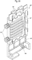
- the rear molded part 220 is shown, which has webs 219 on the upper edge and has a receptacle or recess which is formed as in the front molded part 202 and is only open to the rear.
- a fastening element 221 is inserted into the receptacle as a molded part, which is held in a form-fitting and immovable manner on the molded part 220.
- Two pins 222 are molded onto the fastening element 221 and serve to fix a rear wall.
- the molded part 220 further comprises a groove for receiving the edge of the base and an eyelet 208 for mounting a height adjustment.
- a modified molded part 230 is shown, which is formed higher than the previously described molded parts 202 and 220, wherein two receptacles or recesses are formed in the molded part 230, into each of which a fastening element 203 is inserted.
- the two fastening elements 203 are arranged one above the other, so that the molded part 230 can be used for high side frames.
- the design of the fastening element 203 with the adjusting elements 204 adjustably held therein is designed as in the previous exemplary embodiments.
- a height adjustment with the mounting part 207 and the lever 206 is also shown, which can adjust the base relative to the molded part 230.
- FIG 23 the molded part 230 is shown with two modified fastening elements 221 ', in which, instead of a pin 205 or an angled web 224, a latching element 222' is provided in order to fix a rear wall.
- the latching elements 222 ' can, for example, be inserted into an opening on a rear wall for locking the rear wall.
- one and the same molded part 230 can be used for mounting different rear walls by using different fastening elements 203, 221 or 221 '.
- the same variations can of course also be made on the front to fix the front panel.
Landscapes
- Engineering & Computer Science (AREA)
- General Engineering & Computer Science (AREA)
- Mechanical Engineering (AREA)
- Drawers Of Furniture (AREA)
- Furniture Connections (AREA)
- Connection Of Plates (AREA)
Description
- Die vorliegende Erfindung betrifft einen Schubkasten nach dem Oberbegriff des Anspruches 1.
- Die
DE 10 2014 000 822 A1 offenbart ein Verfahren zur Herstellung einer Zarge einer Schublade, bei dem ein Kunststoffmaterial zu einem Profilstrang extrudiert und abgeschnitten wird und anschließend mit einer Folie überzogen wird. Durch das Extrudieren kann die äußere Folie verstärkt werden, allerdings lässt sich die so hergestellte Seitenzarge schlecht an einer Frontblende oder einer Rückwand eines Schubkastens fixieren. Zudem lassen sich Extrusionsprofile nur mit gleichem Querschnitt herstellen, was die Funktionalität der Formgebung begrenzt. - Die
EP 865 745 -
WO 2008/028811 offenbart einen Schubkasten, bei dem die Seitenzargen über Adapter gehalten sind, die in den Seitenzargen angeordent sind und diese mit einem Boden des Schubkastens verbinden. - Es ist daher Aufgabe der vorliegenden Erfindung, einen Schubkasten zu schaffen, der einfach herstellbar ist und einen flexiblen Aufbau einer Seitenzarge ermöglicht.
- Diese Aufgabe wird mit einem Schubkasten mit den Merkmalen des Anspruches 1 gelöst.
- Bei dem erfindungsgemäßen Schubkasten weist mindestens eine Seitenzarge, vorzugsweise beide Seitenzargen, eine dünnwandige Umhüllung auf, die durch einen inneren Kern abgestützt ist, wobei der innere Kern mindestens zwei Formteile aufweist, die formschlüssig aneinander gehalten sind. Der Einsatz von mindestens zwei Formteilen ermöglicht eine höhere Flexibilität hinsichtlich der Formgebung für den Kern als beim Extrusionsverfahren, so dass die Anbindung von Frontblende und/oder Rückwand erleichtert wird. Zudem kann der stabile Aufbau der Seitenzarge durch die formschlüssige Anordnung der mindestens zwei Formteile gewährleistet werden.
- Vorzugsweise weist der innere Kern mindestens drei Formteile auf, die formschlüssig aneinander gehalten sind. Dabei können mindestens drei unterschiedliche Formteile vorgesehen sein, die nicht baugleich ausgeführt sind.
- Die Formteile erstrecken sich vorzugsweise über die gesamte Länge der Umhüllung, so dass eine gute Abstützung der Umhüllung erfolgt.
- In einer bevorzugten Ausgestaltung ist ein erstes Formteil mit Befestigungsmitteln zur Fixierung der Frontblende versehen. Die Frontblende kann beispielsweise Öffnungen aufweisen, in die jeweils ein Zapfen eingefügt ist. Auch andere Befestigungsmittel für die Frontblende, beispielsweise Schraubverbindungen, können vorgesehen werden.
- Ein zweites Formteil weist vorzugsweise Befestigungsmittel für die Rückwand auf. Das zweite Formteil kann beispielsweise winkelförmig ausgebildet sein und mit einem Steg eine Anlagefläche für die Rückwand ausbilden. Zwischen dem ersten Formteil und dem zweiten Formteil können dann ein oder mehrere dritte Formteile vorgesehen sein, die das erste Formteil mit dem zweiten Formteil verbinden. Die Anzahl der Formteile kann dabei weitgehend frei gewählt werden, je nach Länge des Schubkastens. Die Formteile lassen sich dabei kostengünstig als Spritzgussteile herstellen, die beispielsweise über Nut-Feder-Verbindungen ineinander steckbar sind.
- Für eine stabile Fixierung der Umhüllung kann diese mit den Formteilen verklebt sein. Die Formteile können dabei im Wesentlichen plattenförmig ausgebildet sein und einen seitlich hervorstehenden Steg als Auflage für den Boden aufweisen. Die Umhüllung muss dabei nicht geschlossen ausgebildet sein, sondern kann eine Öffnung zur Durchführung des Bodens aufweisen, der in die Umhüllung randseitig eingreift.
- Die Umhüllung ist vorzugsweise aus einem oder mehreren Metallblechen gebildet. Durch die Abstützung durch den Kern kann die Dicke der Metallbleche kleiner als 0,8 mm, insbesondere kleiner als 0,5 mm, sein.
- Die Formteile bestehen vorzugsweise aus Kunststoff, wobei zur Verstärkung ein formstabiles Material, insbesondere aus Metall oder Kunststoff, vorgesehen sein kann, das an oder in den Formteilen fixiert ist. Für einen filigranen Aufbau kann die gesamte Seitenzarge eine Dicke von weniger als 10 mm, insbesondere weniger als 8 mm, aufweisen. Optional kann die Umhüllung auch einzelne Elemente aus anderen Materialien aufweisen, beispielsweise aus Holz, um optisch ansprechend ausgestaltet zu sein.
- Die Umhüllung kann vorzugsweise ohne Schweißen montiert werden, insbesondere nur durch Verkleben der gebogenen Metallbleche. Durch die Ausfüllung der Umhüllung mit einem Kern bildet die Seitenzarge einen geringeren Klangkörper als ein Hohlprofil aus, so dass auch Geräusche beim Bewegen des Schubkastens gedämpft werden.
- Die Funktionalität der Seitenzarge kann gemäß einer bevorzugten Ausführungsform verbessert werden, wenn der innere Kern mit Formteilen aus unterschiedlichen Höhen in vertikaler Ausrichtung zur Seitenzargenlängsrichtung ausgebildet ist. Die sich durch die unterschiedlichen Höhen der Formteile im inneren Kern ergebenden Freiräume können beispielsweise durch mindestens ein Wandelement aus Glas oder einem anderen optisch ansprechenden Material ausgefüllt sein, beispielsweise gefärbtem, transparenten oder transluzenten Glas, Holz oder Naturstein. Optional ist es zudem möglich, an oder in den Formteilen der Seitenzarge einen Lichtleiter oder Leuchtmittel, vorzugsweise LED, vorzusehen.
- Erfindungsgemäß ist an mindestens einem Formteil eine Nut zur Aufnahme eines Bodens des Schubkastens ausgebildet. Für eine stabile Fixierung des Bodens kann in der Nut eine Aufnahme mit einer Kralle aus metallischem Material zur Fixierung des Bodens vorgesehen sein. Der Boden kann dann durch Einschieben in die Nut kraftschlüssig fixiert werden, wobei die Kralle sich vorzugsweise an einer Unterseite des Bodens in den Boden eingräbt.
- In einer weiteren Ausgestaltung umfasst ein endseitig angeordnetes Formteil, das benachbart zu der Frontblende oder der Rückwand angeordnet ist, eine Aufnahme, in die ein Befestigungselement zur Fixierung der Frontblende oder der Rückwand eingefügt ist. Das Befestigungselement kann dabei relativ zu dem Formteil über einen Verstellmechanismus verschiebbar oder verschwenkbar gelagert sein, so dass über ein Verstellen des Befestigungselementes die Frontblende oder die Rückwand ausgerichtet werden kann. Dabei kann der Verstellmechanismus sowohl zur Tiefenverstellung oder Neigungsverstellung, als auch zur Höhen- oder Seitenverstellung eingesetzt werden. Die Einfügung des Befestigungselementes kann dabei abhängig von der Einbausituation sein, so dass mit ein und demselben Formteil je nach Einsatz eines Befestigungselementes eine unterschiedliche Funktionalität erhalten wird.
- Die Erfindung wird nachfolgend anhand mehrerer Ausführungsbeispiele mit Bezug auf die beigefügten Zeichnungen näher erläutert. Es zeigen:
-
Figur 1 eine perspektivische Ansicht eines erfindungsgemäßen Schubkastens; -
Figur 2 eine Explosionsdarstellung einer Seitenzarge des Schubkastens derFigur 1 ; -
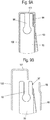
Figuren 3A und 3B zwei Vorderansichten der Seitenzarge derFigur 2 ; -
Figur 4 eine Ansicht des Kerns der Seitenzarge derFigur 2 ; -
Figur 5 eine perspektivische Explosionsdarstellung eines zweiten Ausführungsbeispiels einer erfindungsgemäßen Seitenzarge; -
Figur 6 eine Ansicht des Kerns der Seitenzarge derFigur 5 ; -
Figuren 7A und 7B mehrere schematische Ansichten von nicht erfindungsgemäßen Seitenzargen mit einer unterschiedlichen Umhüllung; -
Figuren 7C bis 7E mehrere schematische Ansichten von erfindungsgemäßen Seitenzargen mit einer unterschiedlichen Umhüllung; -
Figuren 8A bis 8C mehrere Ansichten eines weiteren Ausführungsbeispiels einer Seitenzarge; -
Figuren 9A und 9B zwei Ansichten der Seitenzarge derFigur 8 bei der Montage; -
Figuren 10A und 10B zwei Ansichten eines weiteren Ausführungsbeispiels einer modifizierten Seitenzarge; -
Figuren 11A und11B zwei Ansichten einer modifizierten Seitenzarge; -
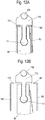
Figuren 12A und 12B zwei Detailansichten der Seitenzarge derFigur 11B ; -
Figuren 13A und 13 B zwei Ansichten eines modifizierten Formteils für eine Seitenzarge; -
Figur 14 eine perspektivische Ansicht einer modifizierten Seitenzarge eines erfindungsgemäßen Schubkastens; -
Figur 15 eine Explosionsdarstellung der Seitenzarge derFigur 14 ; -
Figur 16 eine perspektivische Explosionsdarstellung der Seitenzarge derFigur 15 ohne Umhüllung; -
Figur 17 eine Detailansicht des zur Frontblende benachbarten Formteiles mit einem Befestigungselement; -
Figur 18 eine perspektivische Ansicht des Formteils derFigur 17 ohne Befestigungselement; -
Figur 19 eine perspektivische Ansicht des Befestigungselementes; -
Figur 20 eine perspektivische Ansicht des Formteils mit einem modifizierten Befestigungselement; -
Figur 21 eine perspektivische Ansicht eines modifizierten Formteils mit zwei Befestigungselementen, -
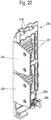
Figur 22 eine Ansicht des Formteils derFigur 21 mit modifizierten Befestigungselementen, und -
Figur 23 eine perspektivische Ansicht des Formteils derFigur 21 mit modifizierten Befestigungselementen. - Ein Schubkasten 1, insbesondere für ein Möbel oder ein Haushaltsgerät, umfasst einen Boden 2, von dem rückseitig eine Rückwand 3 hervorsteht, die auf gegenüberliegenden Seiten mit zwei Seitenzargen 10 verbunden ist. Die Seitenzargen 10 verbinden die Rückwand 3 mit einer nicht dargestellten plattenförmigen Frontblende, die eine Vorderseite des Schubkastens 1 abdeckt. Die Frontblende wird dabei an Zapfen 23 fixiert, die von den Seitenzargen 10 hervorstehen, die in entsprechende Öffnungen an der Frontblende eingefügt und optional verklebt werden können.
- Die Ausgestaltung einer Seitenzarge 10 ist in
Figur 2 im Detail gezeigt, wobei die gegenüberliegende Seitenzarge 10 spiegelbildlich ausgebildet ist und den gleichen Aufbau besitzt. Jede Seitenzarge 10 umfasst eine Umhüllung, die aus zwei Metallblechen 11 und 12 hergestellt ist, die einen inneren Hohlraum umgeben, der durch einen Kern 20 ausgefüllt ist. Der Kern 20 ist aus mehreren Formteilen 21, 24 und 30 gebildet, die formschlüssig aneinander gehalten sind. - Ein erstes Formteil 21 dient zur Fixierung der Frontblende und umfasst zwei hervorstehenden Zapfen 23 an einer Stirnseite. Das Formteil 21 ist im Wesentlichen plattenförmig ausgebildet und weist einen nach innen hervorstehenden Steg 22 zum Abstützen des Bodens 2 auf. Auf der zu den Zapfen 23 gegenüberliegenden Seite ist eine Nut 27 ausgebildet, in die eine stegförmige Feder 26 eines benachbarten Formteils 24 eingreift. Das Formteil 24 weist ebenfalls einen nach innen gerichteten Steg 25 zum Abstützen des Bodens 2 auf.
- Ein weiteres Formteil 30 ist rückseitig vorgesehen, das winkelförmig ausgebildet ist und einen Steg 31 aufweist, der parallel zur Ebene der Rückwand 3 ausgerichtet ist. Der Steg 31 umgreift die Rückwand 3 und kann mit dieser verbunden sein, beispielsweise über Schrauben. Das Formteil 30 weist einen weiteren Abschnitt auf, der zu den benachbarten Formteilen 24 fluchtet. Zwischen dem vorderen Formteil 21 und dem rückwärtigen Formteil 30 sind dabei mehrere mittlere Formteile 24 mit gleicher Formgebung angeordnet, beispielsweise zwischen zwei und acht Formteilen, je nach Länge der Seitenzarge 10.
- In den
Figuren 3A und 3B ist die Seitenzarge derFigur 2 in einer Vorderansicht gezeigt. Die Umhüllung umfasst ein erstes dünnwandiges Metallblech 11 und ein zweites dünnwandiges Metallblech 12, die eine Dicke von kleiner 0,8 mm, insbesondere kleiner 0,5 mm, aufweisen können, beispielsweise zwischen 0,3 mm und 0,5 mm. Das Metallblech 12 weist eine obere Kante 13 auf, die mit einem nach unten abgewinkelten Steg 17 verbunden ist, so dass eine U-förmige obere Kante gebogen ist. Im unteren Bereich ist das ansonsten plattenförmige Metallblech 12 mit einer Abwinklung 14 versehen. Das Metallblech 11 ist im Wesentlichen plattenförmig ausgebildet und umfasst im oberen Bereich eine Stufe 16, an die sich ein Steg 15 anschließt, der sich parallel zu dem Metallblech 11 erstreckt. - Die Montage der Seitenzarge 10 kann so erfolgen, dass zunächst der Kern 20 zusammengesetzt wird und anschließend das Metallblech 12 mit dem Kern 20 verklebt wird. Ferner wird das Metallblech 11 in den Zwischenraum zwischen dem Steg 17 und einer Wand des Kerns 20 eingefügt, und das Metallblech 11 wird ebenfalls mit dem Kern 20 verklebt. Die so gebildete Einheit kann dann mit der Rückwand 3, der Frontblende und dem Boden 2 zu einem Schubkasten zusammengesetzt werden. Zur Montage der Rückwand sind Öffnungen 32 in dem Steg 31 ausgespart, in die Schrauben eingedreht werden können.
- Für den Boden 2 ist an den Formteilen 21, 24 und 30 neben den Stegen 22 eine nutförmige Aufnahme 28 ausgebildet, in die eine Seitenkante des Bodens 2 einfügbar ist, so dass diese auch gegen Anheben gesichert ist. Wie insbesondere in
Figur 3B erkennbar ist, umgibt die Umhüllung mit den Metallblechen 11 und 12 den Kern 20 nicht vollständig, sondern ein Teilbereich für den Boden 2 und ein Bereich unterhalb der Stege 22 ist nicht umhüllt, da dieser in der Regel nicht sichtbar ist. - In
Figur 4 ist ein zusammengesetzter Kern aus den Formteilen 21, 24 und 30 gezeigt. Die Formteile 21, 24 und 30 bilden an einer Oberkante eine Aussparung 19 aus, in die der obere Steg 15 mit der Stufe 16 des Metallbleches 11 eingefügt werden kann, so dass auch das Metallblech 11 formschlüssig an dem Kern 20 festgelegt ist. - In
Figur 5 ist ein weiteres Ausführungsbeispiel einer Seitenzarge gezeigt, die ähnlich wie inFigur 2 ausgebildet ist, allerdings weisen die Formteile 21, 24 und 30 eine Durchführung oder mehrere Durchführungen für Verstärkungselemente 40 und 41 auf. Ein erstes Band oder streifenförmiges Verstärkungselement 40, beispielsweise aus einem Stahlblech oder aus einem harten Kunststoff, durchgreift die mittleren Formteile 24 und weist endseitig jeweils einen Vorsprung 42 oder eine Ausnehmung mit darin eingestecktem Stift oder Bolzen auf, der in eine Öffnung 43 des vorderen Formteils 21 und eine Öffnung 33 des rückseitigen Formteils 30 einfügbar ist. Durch das bandförmige Verstärkungselement 40 kann die Seitenstabilität und die Belastbarkeit des Kerns auf Zug erhöht werden. Zudem ist im unteren Bereich ein stabförmiges Verstärkungselement 41 durch Öffnungen 29 in den Formteilen 21, 24 und 30 durchgeführt, das beispielsweise in den Öffnungen 29 verklebt ist. Auch andere mechanische Fixierungen für das Verstärkungsteil 41 können vorgesehen werden. - In
Figur 6 ist der zusammengesetzte Kern 20 mit den Verstärkungselementen 40 und 41 gezeigt, die zur Stabilisierung der miteinander verbundenen Formteile 21, 24 und 30 beitragen. Im Übrigen ist dieses Ausführungsbeispiel so ausgebildet wie das erste Ausführungsbeispiel. - In den
Figuren 7A bis 7F sind verschiedene Varianten für eine Umhüllung eines Kerns 20 gezeigt, der nur noch schematisch dargestellt ist und so ausgebildet sein kann, wie dies in denFiguren 2 oder5 gezeigt ist. - In
Figur 7A ist ein nicht erfindungsgemäßes plattenförmiges Metallblech 11' gezeigt, das mit dem Kern 20 verklebt ist, und ein zweites Metallblech 12' ist im oberen Bereich U-förmig verbogen und ebenfalls mit den Kern 20 verklebt. Es wurde auf die Stufe 16 bei dem Metallblech und die Abwinklung 14 bei dem Metallblech verzichtet. - Bei dem in
Figur 7B gezeigten, nicht erfindungsgemäßen, Ausführungsbeispiel ist die Umhüllung aus drei Teilen gebildet, nämlich zwei plattenförmigen Metallblechen 50 und 51, die in oberen Bereich durch ein U-förmiges Profil 52 überdeckt sind, das mit den beiden Schenkeln die Außenwände der Metallbleche 50 und 51 übergreift. - In
Figur 7C ist eine Variante gezeigt, bei der der Kern 20 durch eine einteilige Umhüllung 55 überdeckt ist, die entsprechend dem Kern gebogen ist, wobei eine Aussparung zur Durchführung des Bodens 2 weggelassen wurde. - In
Figur 7D ist die Umhüllung durch zwei Metallbleche 60 und 61 gebildet, die an der Innenseite und Außenseite plattenförmig ausgebildet sind und im oberen Bereich U-förmig gebogen sind, wobei in dem Verbindungsbereich der Schenkel in eine nutförmige Aufnahme in dem Kern 20 eingreift. Dadurch kann die Stabilität der Einheit aus Umhüllung und Kern 20 erhöht werden, insbesondere wenn auch die in den Kern 20 eingreifenden Schenkel mit dem Kern 20 verklebt sind. - In einem in
Figur 7E gezeigten Ausführungsbeispiel ist die Umhüllung 70 wieder einteilig ausgebildet, ähnlich wie inFigur 7C , allerdings ist oberhalb des Schubkastens1 eine Abwinklung 71 vorgesehen, die auf dem Boden 2 aufliegt, so dass kein Spalt zwischen der Oberseite des Bodens 2 und der Umhüllung sichtbar ist. - Die
Figur 7F zeigt ein Ausführungsbeispiel einer Umhüllung mit einer Innenwand 80 und einer Außenwand 81 aus abgewinkelten Metallblechen, die einen kern 20 umgeben. Zur Fixierung der Innenwand 80 und der Außenwand 81 an dem Kern 20 ist ein Einsteckteil 82 vorgesehen, das mit einem Rastelement 83, insbesondere einem Stift mit einem Rastkopf, in eine Aufnahme an dem Kern 20 einsteckbar ist. Durch das Einsteckteil 82 können die Innenwand und die Außenwand 81 nach Art eines Keders fixiert werden. Hierfür kann die Innenwand 80 und die Außenwand 81 zumindest teilweise mit einem Endabschnitt in die Aufnahme an dem Kern 20 eingreifen und durch das Einsteckteil 82 formschlüssig oder kraftschlüssig fixiert werden. - Die dargestellten Ausführungsbeispiele können beliebig kombiniert werden. Beispielsweise kann der Kern 20 nur ein Verstärkungselement 40 oder 41 aufweisen oder mehr als die dargestellten Verstärkungselemente 40 und 41. Die Verstärkung muss sich nicht durch die Formteile erstrecken, sondern kann auch an einer Oberfläche der Formteile fixiert sein, beispielsweise durch Verkleben.
- Die Formteile 21, 24 und 30 sind über Nut-Feder-Verbindungen formschlüssig aneinander gehalten. Es ist natürlich auch möglich, andere Formschlussverbindungen, beispielsweise Schwalbenschwanzverbindungen, Hakenverbindungen oder andere Steck- oder Schwenkverbindungen, vorzusehen.
- Die Formteile 21, 24 und 30 sind aus Kunststoff im Spritzgussverfahren hergestellt. Je nach Länge der Seitenzarge können mehr oder weniger mittlere Formteile 24 zwischen dem Formteil 21 und dem rückseitigen Formteil 30 eingesetzt werden.
- In den
Figuren 8A bis 8C ist ein weiteres Ausführungsbeispiel einer Seitenzarge 10' gezeigt, die ein vorderes Formteil 90, ein mittleres Formteil 91 und ein hinteres Formteil 92 aufweist. Das mittlere Formteil 91 weist eine geringere Höhe in vertikaler Seitenzargenlängsrichtung als die Formteile 90 und 92 auf. Auf das mittlere Formteil wird ein Wandelement aus Glas oder einem anderen optisch ansprechenden Material aufgesetzt und bleibt von außen sichtbar. Hierfür ist eine innere Umhüllung an der Innenseite der Seitenarge vorgesehen, die einen vorderen Steg 93 und einen hinteren Steg 95 aufweist, zwischen denen eine Aussparung 94 ausgebildet ist, in der das Wandelement aus Glas sichtbar bleibt. Das vordere Formteil 90 und das hintere Formteil 92 sind über das mittlere Formteil 91 miteinander verbunden, an dem eine Nut zur Aufnahme eines Bodens für den Schubkasten vorgesehen ist. Der Steg 93 überdeckt dabei das vordere Formteil 90 und steht über dieses in Zargenlängsrichtung hervor, so dass das Wandelement aus Glas teilweise durch den Steg 93 und den hinteren Steg 95 überdeckt ist und dadurch das Wandelement 112 in vertikaler Richtung zur Seitenzargenlängsrichtung gehalten wird. Auf ähnliche Weise wird an der Außenseite der Zarge eine äußere Umhüllung 100 mit zwei Stegen 103 und 104 vorgesehen, die optional auch mit den Stegen 93 und 95 verbunden sind, wobei an dem vorderen Steg 103 eine U-förmige Kante 101 angeformt ist, die eine Oberseite des Formteils 90 übergreift. Zudem wird ein Endabschnitt des Wandelements 112 übergriffen, so dass das Wandelement 91 durch die Umhüllungen gehalten ist. Das vordere Formteil 90 und das hintere Formteil 92 sind mit dem Wandelement aus Glas in einer Ebene angeordnet und bilden in Richtung der inneren und äußeren Umhüllung nahezu plane Anlageflächen aus. - An den Formteilen 90 und 92 ist an einer Oberseite eine Nut 96 ausgebildet, die zur Montage weiterer Bauteile, beispielsweise Abdeckleisten oder Aufsatzzargen, eingesetzt werden kann. In dem Ausführungsbeispiel der
Figuren 8 und9 ist die Nut 96 allerdings nicht belegt. - Wie die
Figuren 9A und 9B zeigen, wird zur Montage das Formteil 90 vorgesehen, bevor die innere Umhüllung mit dem Steg 93 und die äußere Umhüllung 100 mit der U-förmigen Kante 101 montiert werden. An dem Steg 93 ist eine stufenförmige Kante 98 ausgebildet, die in eine entsprechende Aufnahme 97 an dem Formteil 90 eingreift, so dass die innere Umhüllung mit dem Steg 93 formschlüssig an dem Formteil 90 gehalten ist. Die gestufte Kante 98 wird dann durch die U-förmige Kante 101 der äußeren Umhüllung 100 überdeckt, wobei die Umhüllungen optional auch miteinander verklebt werden können. - In den
Figuren 10A und 10B ist ein modifiziertes Ausführungsbeispiel einer Seitenzarge gezeigt, bei der eine innere Umhüllung 93' keine Aussparung 94 aufweist, und im Inneren mehrere Formteile 90 vorgesehen sind, wie dies vorstehend schon erläutert wurde. An der Außenseite ist eine äußere Umhüllung 100 vorgesehen, die mit einer U-förmigen Kante 101 die Formteile 90 an einer Oberseite umgreift. In den Formteilen 90 ist eine Nut 96 ausgespart, in die ein Lichtleiter 105 eingelegt ist. In den Lichtleiter 105 wird Licht eingestrahlt, beispielsweise über eine LED, die in der Seitenzarge, der Rückwand oder der Frontblende angeordnet ist. In der U-förmigen Kante 101 sind mehrere Öffnungen 102 ausgespart, so dass Licht über den Lichtleiter 105 durch die Öffnungen 102 abgestrahlt werden kann, was einen optisch ansprechenden Effekt ergibt. - In
Figur 11A und11B ist ein gegenüberFigur 10 modifiziertes Ausführungsbeispiel gezeigt, bei dem in die Nut 96 an den Formteilen 90 ein Einsteckteil 110 eingefügt wird, an dessen Oberseite ein Lichtleiter 105 angeordnet ist. Der stabförmige Lichtleiter 105 bleibt nach der Montage von außen sichtbar und kann zur Verteilung von Licht dienen, das in eine Stirnseite des Lichtleiters 105 eingestrahlt wird. Die innere Umhüllung 93' erstreckt sich bis kurz unterhalb des Lichtleiters 105, und auch die äußere Umhüllung überdeckt den Lichtleiter 105 nicht. - Wie in den
Figuren 12A und 12B gezeigt, kann die innere Umhüllung 93' an der Oberseite eine gebogene Kante 98' und die äußere Umhüllung eine gebogene Kante 101 aufweisen, die zwischen einer Oberseite des Formteils und einem verdickten Kopfabschnitt des Einsteckteils 110 eingefügt werden. Somit können über das Einsteckteil 110 die Umhüllungen 93' und 100' in Position gehalten werden. Das Einsteckteil 110 weist einen verdickten Fußabschnitt 111 auf, der in eine entsprechende Verbreiterung der Nut 96 eingefügt ist. An der Oberseite des Einsteckteils 110 ist der Lichtleiter 105 fixiert, insbesondere verklebt oder klemmend festgelegt. - In den
Figuren 13A und 13B ist ein modifiziertes Formteil aus Kunststoff für eine Seitenzarge gezeigt, wobei die metallische Umhüllung weggelassen wurde. Die Seitenzarge umfasst mindestens einem Formteil 120 mit einer Nut 121 zur Aufnahme eines Bodens des Schubkastens. Vorzugsweise erstrecken sich die Formteile 120 über die gesamte Länge der Seitenzarge. Oberhalb der Nur ist ein Wandelement 122 vorgesehen, das in Längsrichtung der Seitenzarge auf einer Stirnseite eine Nut 123 aufweist, in die eine hervorstehende Feder 124 eines benachbarten Formteils 120 eingesteckt werden kann. Dadurch können mehrere Formteile 120 formschlüssig über die gesamte Länge einer Seitenzarge ineinander gesteckt werden. - In einem Boden der Nut 121 ist eine Öffnung 125 vorgesehen, die zur Fixierung eines Metallwinkels 127 dient. Der Metallwinkel 127 umfasst einen vertikalen Schenkel 128 mit Montageöffnungen 129, die in der montierten Position innerhalb der Öffnung 125 angeordnet sind. An einem unteren horizontalen Schenkel 131 der Nut 121 ist eine Aufnahme ausgebildet, in die ein zweiter Schenkel 130 des Metallwinkels 127 eingefügt ist. An dem zweiten Schenkel 130 ist eine Kralle 133 mit nach oben ragenden Zähnen ausgebildet die von zwei Stegen mit Montageöffnungen 134 umgeben ist. Um einen Boden des Schubkastens zu fixieren, kann dieser randseitig in die Nut eingeschoben und kraftschlüssig fixiert werden, wobei die Kralle 133 sich an einer Unterseite des Bodens in diesen eingräbt. Die Klemmkräfte auf die Krall 133 verteilen sich dann auf den horizontalen Schenkel 131, der an gegenüberliegenden Enden durch nach unten ragende Stege 126 abstützbar ist. Die Oberseite des zweiten Schenkels 130 und die Oberseite des horizontalen Schenkel 131 können zu Stützung des Bodens im Wesentlichen flächenbündig ausgerichtet sein.
- In den
Figuren 14 und15 ist eine modifizierte Seitenzarge 10' für einen Schubkasten 1 dargestellt. Die Seitenzarge 10' umfasst eine Umhüllung, die aus zwei gebogenen Metallblechen 11' und 12' hergestellt ist und einen inneren Kern umgibt, der ein oder mehrere mittlere Formteile 201, ein zur Frontblende gewandtes endseitiges Formteil 202 und ein zur Rückwand gewandtes endseitiges Formteil 220 umfasst. Die mittleren Formteile 201 können dabei aus Kunststoff im Spritzgussverfahren hergestellt sein und umfassen eine Gitterstruktur, so dass, bezogen auf das Volumen des Formteils 201, nur wenig Material benötigt wird. Unter dem Metallblech 12' ist an den Formteilen 201, 202 und 220 eine Nut 209 zum Einfügen eines Randes eines Bodens des Schubkastens ausgebildet. An den Formteilen 201, 202 und 220 befinden sich an einer Oberseite eine Vielzahl nach oben ragender Stege 219, an denen die beiden Metallbleche 11' und 12' der Umhüllung festlegbar sind, wobei die Art der Befestigung auch entsprechend einem der vorangegangenen Ausführungsbeispiele ausgestaltet sein kann. - Das zur Frontblende gewandte Formteil 202 ist mit einer Aussparung oder Aufnahme versehen, in die ein Befestigungselement 203 eingefügt ist. Das Befestigungselement 203 ist dabei an mindestens drei Seiten, vorzugsweise an mindestens vier Seiten, von dem Formteil 202 umgeben. Das Befestigungselement 203 umfasst ein Verstellelement 204, das relativ zu dem Befestigungselement 203 verstellbar ist. An dem Verstellelement 204 sind Befestigungsmittel 205 zur Fixierung der Frontblende vorgesehen, wobei die Befestigungsmittel 205 in dem dargestellten Ausführungsbeispiel als Zapfen ausgebildet sind, die in entsprechende Bohrungen oder Öffnungen an der Frontblende eingesteckt werden.
- Zudem ist an dem Formteil 202 eine Höhenverstellung vorgesehen, wobei ein Montageteil 207 im unteren Bereich des Formteils 202 festlegbar ist, an dem eine Kurvenführung ausgebildet ist, die mit einem Hebel 206 zusammenwirkt, der bei einer Drehbewegung die Position der Frontblende relativ zu dem Boden verstellen kann.
- Das benachbart zur Frontblende angeordnete Formteil 202 kann baugleich ausgebildet sein wie ein an der gegenüberliegenden Seitenzarge angeordnetes Formteil, das der Rückwand zugewandt ist. Das zur Rückblende zugewandte Formteil 220 an derselben Seitenzarge ist spiegelsymmetrisch ausgebildet zu einer mittleren Ebene senkrecht zur Längsrichtung der Seitenzarge. An dem Formteil 220 ist ein modifiziertes Befestigungselement 221 in die Aufnahme eingefügt, das im Wesentlichen formschlüssig an dem Formteil 220 gehalten ist und zur Fixierung der Seitenzarge an der Rückwand dient.
- In
Figur 17 ist das zur Frontblende benachbarte Formteil 202 mit dem Befestigungselement 203 im Detail dargestellt. An dem Befestigungselement 203 befindet sich ein drehbarer Exzenter 210, der in einer Öffnung 214 an einem Wandabschnitt des Formteils 202 (Figur 18 ) drehbar gelagert ist. Über den Exzenter 210 kann das Verstellelement 204 relativ zu dem Befestigungselement 203 in der Höhe verstellt werden. Hierfür ist das Verstellelement 204 mit vertikalem Spiel innerhalb des Befestigungselementes 203 aufgenommen, wobei zur Führung ein oder mehrere Stege 212 an dem Befestigungselement 203 ausgebildet sind, die in entsprechende Aussparungen 213 oder Führungsaufnahmen eingreifen. - An dem Befestigungselement 203 ist ferner eine Seitenverstellung 211 vorgesehen die an dem Verstellelement 204 angeordnet ist. Über die Seitenverstellung 211 kann die Position des Verstellelementes 204 in eine Richtung horizontal und senkrecht zur Längsrichtung der Seitenzarge verändert werden.
- An dem Formteil 202 befindet sich ferner eine Nut 209 zur Aufnahme eines Randes des Bodens des Schubkastens, wobei die Position des Bodens über eine Höhenverstellung verändert werden kann. Die Höhenverstellung mit dem Hebel 206 ist dabei an einer Öse 208 drehbar gelagert.
- In
Figur 18 ist das Formteil 202 ohne das Befestigungselement 203 dargestellt, und es ist erkennbar, dass das Befestigungselement 203 U-förmig umschlossen ist und an einer vierten Seite an einem Wandabschnitt zumindest teilweise anliegt. - In
Figur 19 ist das Befestigungselement 203 gezeigt, und es ist der Exzenter 210 erkennbar, mittels dem das Verstellelement 204 in der Höhe relativ zu dem Befestigungselement 203 verstellbar ist. Ferner ist die Seitenverstellung 211 zu sehen, die eine Positionierung des Verstellelementes 204 in eine Richtung senkrecht zur Ebene der Seitenzarge ermöglicht. An dem Verstellelement 204 sind zwei Zapfen als Befestigungsmittel 205 zur Festlegung der Frontblende ausgebildet. - In
Figur 20 ist das rückwärtige Formteil 220 gezeigt, das am oberen Rand Stege 219 aufweist und eine Aufnahme oder Aussparung besitzt, die wie bei dem vorderen Formteil 202 ausgebildet ist und nur nach hinten offen ist. In die Aufnahme ist ein Befestigungselement 221 als Formteil eingefügt, das formschlüssig und unverschieblich an dem Formteil 220 gehalten ist. An dem Befestigungselement 221 sind zwei Zapfen 222 angeformt, die zur Fixierung einer Rückwand dienen. Das Formteil 220 umfasst ferner eine Nut zur Aufnahme des Randes des Bodens und eine Öse 208 zur Montage einer Höhenverstellung. - In
Figur 21 ist ein modifiziertes Formteil 230 dargestellt, das höher ausgebildet ist als die zuvor beschriebenen Formteile 202 und 220, wobei in dem Formteil 230 zwei Aufnahmen oder Aussparungen ausgebildet sind, in die jeweils ein Befestigungselement 203 eingefügt ist. Die beiden Befestigungselemente 203 sind dabei übereinander angeordnet, so dass das Formteil 230 für hohe Seitenzargen einsetzbar ist. Im Übrigen ist die Gestaltung des Befestigungselementes 203 mit den darin verstellbar gehaltenen Verstellelementen 204 wie bei den vorangegangenen Ausführungsbeispielen ausgebildet. Im unteren Bereich des Formteils 230 ist ferner eine Höhenverstellung mit dem Montageteil 207 und dem Hebel 206 dargestellt, der den Boden relativ zu dem Formteil 230 verstellen kann. - In
Figur 22 ist das Formteil 230 nicht mit den Befestigungselementen 203, sondern mit modifizierten Befestigungselementen 221 gefüllt, die formschlüssig an dem Formteil 230 fixiert sind. Dabei sind zwei Befestigungselemente 221 übereinander vorgesehen, an denen abgewinkelte Stege 224 gehalten sind, die zur Montage einer Rückwand dienen. - In
Figur 23 ist das Formteil 230 mit zwei modifizierten Befestigungselementen 221' dargestellt, bei denen statt einem Zapfen 205 oder einem abgewinkelten Steg 224 ein Rastelement 222' vorgesehen ist, um eine Rückwand zu fixieren. Die Rastelemente 222' können beispielsweise in eine Öffnung an einer Rückwand zum Verrasten der Rückwand eingefügt werden. - Wie die
Figuren 21 bis 23 zeigen, kann ein und dasselbe Formteil 230 durch Einsatz unterschiedlicher Befestigungselemente 203, 221 oder 221' zur Montage unterschiedlicher Rückwände eingesetzt werden. Dieselben Variationen können natürlich auch an der Vorderseite zur Fixierung der Frontblende vorgenommen werden. -
- 1
- Schubkasten
- 2
- Boden
- 3
- Rückwand
- 10, 10'
- Seitenzarge
- 11, 11'
- Metallblech
- 12, 12'
- Metallblech
- 13
- Kante
- 14
- Abwinklung
- 15
- Steg
- 16
- Stufe
- 17
- Steg
- 19
- Aussparung
- 20
- Kern
- 21
- Formteil
- 22
- Steg
- 23
- Zapfen
- 24
- Formteil
- 25
- Steg
- 26
- Feder
- 27
- Nut
- 28
- Aufnahme
- 29
- Öffnung
- 30
- Formteil
- 31
- Steg
- 32
- Öffnung
- 33
- Öffnung
- 40
- Verstärkungselement
- 41
- Verstärkungselement
- 42
- Vorsprung
- 43
- Öffnung
- 50
- Metallblech
- 51
- Metallblech
- 52
- Profil
- 55
- Umhüllung
- 60
- Metallblech
- 61
- Metallblech
- 70
- Umhüllung
- 71
- Abwinklung
- 80
- Innenwand
- 81
- Außenwand
- 82
- Einsteckteil
- 83
- Rastelement
- 90
- Formteil
- 91
- Formteil
- 92
- Formteil
- 93
- Steg
- 93'
- Umhüllung
- 94
- Aussparung
- 95
- Steg
- 96
- Nut
- 97
- Aufnahme
- 98, 98'
- Kante
- 99
- Steg
- 100
- Umhüllung
- 100'
- Umhüllung
- 101
- Kante
- 102
- Öffnung
- 103
- Steg
- 104
- Steg
- 105
- Lichtleiter
- 110
- Einsteckteil
- 111
- Fußabschnitt
- 112
- Wandelement
- 120
- Formteil
- 121
- Nut
- 122
- Wandelement
- 123
- Nut
- 124
- Feder
- 125
- Öffnung
- 126
- Steg
- 127
- Metallwinkel
- 128
- vertikaler Schenkel
- 129
- Montageöffnung
- 130
- Steg
- 131
- horizontaler Schenkel
- 133
- Kralle
- 201
- Formteil
- 202
- Formteil
- 203
- Befestigungselement
- 204
- Verstellelement
- 205
- Befestigungsmittel
- 206
- Hebel
- 207
- Montageteil
- 208
- öse
- 209
- Nut
- 210
- Exzenter
- 211
- Seitenverstellung
- 212
- Steg
- 213
- Aussparung
- 214
- Öffnung
- 219
- Steg
- 220
- Formteil
- 221, 221'
- Befestigungselement
- 222
- Zapfen
- 222'
- Rastelement
- 224
- Steg
- 230
- Formteil
Claims (17)
- Schubkasten (1) mit zwei Seitenzargen (10), einem Boden (2), einer Rückwand (3) und einer Frontblende, wobei mindestens eine Seitenzarge (10) eine dünnwandige Umhüllung (11, 12) aufweist, die durch einen inneren Kern (20) abgestützt ist, wobei der innere Kern (20) mindestens zwei Formteile (21, 24, 30, 90, 91, 92, 120, 202, 220, 230) aufweist, die formschlüssig aneinander gehalten sind, dadurch gekennzeichnet, dass an mindestens einem Formteil (120) eine Nut (121) zur Aufnahme eines Bodens des Schubkastens ausgebildet ist.
- Schubkasten nach Anspruch 1, dadurch gekennzeichnet, dass der innere Kern (20) mindestens drei Formteile (21, 24, 30) aufweist, die formschlüssig aneinander gehalten sind.
- Schubkasten nach Anspruch 1 oder 2, dadurch gekennzeichnet, dass die Formteile (21, 24, 30, 202, 220, 230) sich im Wesentlichen über die gesamte Länge der Umhüllung (11, 12) erstrecken.
- Schubkasten nach einem der vorhergehenden Ansprüche, dadurch gekennzeichnet, dass ein erstes Formteil (21) mit Befestigungsmitteln (23), insbesondere hervorstehenden Zapfen, zur Fixierung der Frontblende versehen ist.
- Schubkasten nach einem der vorhergehenden Ansprüche, dadurch gekennzeichnet, dass ein zweites Formteil (30) Befestigungsmittel (31) für die Rückwand (3) aufweist.
- Schubkasten nach einem der vorhergehenden Ansprüche, dadurch gekennzeichnet, dass die Formteile (21, 24, 30) als Spritzgussteile hergestellt sind.
- Schubkasten nach einem der vorhergehenden Ansprüche, dadurch gekennzeichnet, dass die Formteile (21, 24, 30) über Nut-Feder-Verbindungen (26, 27) ineinander steckbar sind.
- Schubkasten nach einem der vorhergehenden Ansprüche, dadurch gekennzeichnet, dass die Umhüllung (11, 12) mit den Formteilen (21, 24, 30) verklebt ist.
- Schubkasten nach einem der vorhergehenden Ansprüche, dadurch gekennzeichnet, dass die Formteile (21, 24, 30) im Wesentlichen plattenförmig ausgebildet sind und einen seitlich hervorstehenden Steg (22, 25) als Auflager für den Boden (2) aufweisen.
- Schubkasten nach einem der vorhergehenden Ansprüche, dadurch gekennzeichnet, dass die Umhüllung (11, 12) aus einem oder mehreren Metallblechen, insbesondere Stahlblechen, gebildet ist, wobei die Metallbleche bevorzugt eine Dicke kleiner 0,8 mm, insbesondere kleiner 0,5 mm, aufweisen.
- Schubkasten nach einem der vorhergehenden Ansprüche, dadurch gekennzeichnet, dass in oder an den Formteilen (21, 24, 30) eine Verstärkung (40, 41) aus einem formstabilen Material, insbesondere Metall oder Kunststoff, vorgesehen ist.
- Schubkasten nach einem der vorhergehenden Ansprüche, dadurch gekennzeichnet, dass die Seitenzargen (10) eine Dicke kleiner 10 mm, insbesondere kleiner 8 mm, aufweisen.
- Schubkasten nach einem der vorhergehenden Ansprüche, dadurch gekennzeichnet, dass die Umhüllung (11, 12) zumindest teilweise Dekorelemente aus Holz aufweist.
- Schubkasten nach einem der vorhergehenden Ansprüche, dadurch gekennzeichnet, dass der innere Kern mindestens zwei Formteile (90, 91) mit unterschiedlichen Höhen in vertikaler Richtung zur Seitenzargenlängsrichtung aufweist.
- Schubkasten nach einem der vorhergehenden Ansprüche, dadurch gekennzeichnet, dass an oder in den Formteilen der Seitenzarge ein Lichtleiter oder Leuchtmittel (105) vorgesehen ist.
- Schubkasten nach einem der vorhergehenden Ansprüche, dadurch gekennzeichnet, dass in der Nut eine Aufnahme mit einer Kralle (133) aus metallischem Material zur Fixierung des Bodens vorgesehen ist.
- Schubkasten nach einem der vorhergehenden Ansprüche, dadurch gekennzeichnet, dass ein endseitig benachbart zu der Frontblende oder der Rückwand (3) angeordnetes Formteil (202, 220, 230) eine Aufnahme aufweist, in die ein Befestigungselement (203, 221, 221') zur Fixierung der Frontblende oder der Rückwand (3) an dem endseitigen Formteil (202, 220, 230) eingefügt ist, wobei das Befestigungselement (203, 221, 221') bevorzugt relativ zu dem Formteil (202, 220, 230) über einen Verstellmechanismus (206, 210, 221) verschiebbar oder verschwenkbar gelagert ist.
Applications Claiming Priority (3)
| Application Number | Priority Date | Filing Date | Title |
|---|---|---|---|
| DE102016122824 | 2016-11-25 | ||
| DE102017121597.2A DE102017121597A1 (de) | 2016-11-25 | 2017-09-18 | Schubkasten |
| PCT/EP2017/079642 WO2018095820A1 (de) | 2016-11-25 | 2017-11-17 | Schubkasten |
Publications (2)
| Publication Number | Publication Date |
|---|---|
| EP3544467A1 EP3544467A1 (de) | 2019-10-02 |
| EP3544467B1 true EP3544467B1 (de) | 2020-09-16 |
Family
ID=62117381
Family Applications (1)
| Application Number | Title | Priority Date | Filing Date |
|---|---|---|---|
| EP17800543.5A Active EP3544467B1 (de) | 2016-11-25 | 2017-11-17 | Schubkasten |
Country Status (8)
| Country | Link |
|---|---|
| US (1) | US10729242B2 (de) |
| EP (1) | EP3544467B1 (de) |
| JP (1) | JP7044779B2 (de) |
| KR (1) | KR102433108B1 (de) |
| CN (1) | CN109922695B (de) |
| DE (1) | DE102017121597A1 (de) |
| ES (1) | ES2832712T3 (de) |
| WO (1) | WO2018095820A1 (de) |
Cited By (1)
| Publication number | Priority date | Publication date | Assignee | Title |
|---|---|---|---|---|
| DE102021115892A1 (de) | 2021-06-18 | 2022-12-22 | Paul Hettich Gmbh & Co. Kg | Verstellvorrichtung für einen Schubkasten |
Families Citing this family (16)
| Publication number | Priority date | Publication date | Assignee | Title |
|---|---|---|---|---|
| DE102018123054A1 (de) * | 2018-09-19 | 2020-03-19 | Paul Hettich Gmbh & Co. Kg | Schubkasten und Einheit aus einer Auszugsführung und einem Schubkasten |
| DE102019106308A1 (de) * | 2019-03-12 | 2020-09-17 | Paul Hettich Gmbh & Co. Kg | Schubkasten |
| DE102019111861A1 (de) * | 2019-05-07 | 2020-11-12 | Paul Hettich Gmbh & Co. Kg | Schubkastenwandelement |
| USD938212S1 (en) * | 2019-05-16 | 2021-12-14 | Julius Blum Gmbh | Furniture drawer |
| DE102019113101A1 (de) * | 2019-05-17 | 2020-11-19 | Paul Hettich Gmbh & Co. Kg | Seitenzarge für einen Schubkasten |
| DE102019113102A1 (de) * | 2019-05-17 | 2020-11-19 | Paul Hettich Gmbh & Co. Kg | Schubkastenwand |
| AT522842B1 (de) * | 2019-07-18 | 2023-11-15 | Blum Gmbh Julius | Schubladenrückwand |
| DE102019122854A1 (de) * | 2019-08-26 | 2021-03-04 | Paul Hettich Gmbh & Co. Kg | Seitenzarge |
| DE102020119901A1 (de) * | 2020-07-28 | 2022-02-03 | Paul Hettich Gmbh & Co. Kg | Adaptereinheit zur Verbindung eines Schubkastenbodens mit einer Seitenzarge eines Schubkastens, Seitenzarge und Schubkasten |
| DE102020126359A1 (de) | 2020-10-08 | 2022-04-14 | Grass Gmbh | Schubladenwandelement für eine Schublade |
| AT524493B1 (de) * | 2020-12-02 | 2024-10-15 | Blum Gmbh Julius | Verfahren zur manuellen und/oder maschinellen Herstellung einer doppelwandigen Schubladenzarge |
| DE102021102667B4 (de) * | 2021-02-04 | 2023-12-07 | Paul Hettich Gmbh & Co. Kg | Schubelement mit einer Beleuchtungseinrichtung und Möbel mit einem solchen Schubelement |
| CN113017315B (zh) * | 2021-03-25 | 2022-10-14 | 东莞市大境华家具发展有限公司 | 木饰面板阴角连接结构、其成型工艺及具有该结构的木柜 |
| AT525777B1 (de) * | 2021-12-21 | 2025-06-15 | Blum Gmbh Julius | Doppelwandige Schubladenzarge |
| CN117432693A (zh) * | 2022-07-12 | 2024-01-23 | 川湖科技股份有限公司 | 家具及其家具组件 |
| DE102023130069A1 (de) * | 2023-10-31 | 2025-04-30 | Paul Hettich Gmbh & Co. Kg | Seitenzarge und Schubkasten |
Family Cites Families (27)
| Publication number | Priority date | Publication date | Assignee | Title |
|---|---|---|---|---|
| GB1189907A (en) * | 1967-10-16 | 1970-04-29 | Leslie William Llewelly Alston | Improvements in or relating to Drawers for Furniture |
| JPS4916483Y1 (de) * | 1968-10-03 | 1974-04-25 | ||
| US3791002A (en) * | 1972-07-31 | 1974-02-12 | Armstrong Cork Co | Method of making a thermoplastic drawer |
| US4440460A (en) * | 1981-08-06 | 1984-04-03 | Brighoff John C | Furniture and drawer therefor |
| CN2164727Y (zh) * | 1993-02-23 | 1994-05-18 | 陈安男 | 组装式桌柜 |
| CN2225803Y (zh) * | 1995-07-10 | 1996-05-01 | 郑永胜 | 可伸展组装的抽屉 |
| US5597221A (en) * | 1995-11-01 | 1997-01-28 | Sauder Woodworking Co. | Drawer assembly having interlocking members |
| US5678509A (en) * | 1995-11-08 | 1997-10-21 | Dillon; Charles E. | All-in-one litter box, sleeping area, and food and water bowl system useable as a pet carrier |
| JP2919784B2 (ja) * | 1996-07-18 | 1999-07-19 | ナショナル住宅産業株式会社 | 壁状収納装置 |
| AT407332B (de) * | 1997-03-21 | 2001-02-26 | Blum Gmbh Julius | Schublade |
| AT409069B (de) * | 1997-07-03 | 2002-05-27 | Blum Gmbh Julius | Schubladenzarge |
| DE202005008286U1 (de) * | 2005-05-27 | 2006-10-05 | Paul Hettich Gmbh & Co. Kg | Schubkasten |
| DE202007001780U1 (de) | 2006-09-08 | 2008-01-10 | Paul Hettich Gmbh & Co. Kg | Schubkasten |
| GB2437060A (en) * | 2006-12-19 | 2007-10-17 | Crystal Clear Internat Ltd | Cosmetic lotion dispenser with massager |
| CN100450397C (zh) * | 2007-01-15 | 2009-01-14 | 谷丽华 | 金属橱柜面板及其制作方法 |
| DE202007002791U1 (de) * | 2007-02-22 | 2008-06-26 | Rudolf Henrichsmeyer Formaplan Gmbh & Co. Kg | Möbelbauteil |
| DE202009005203U1 (de) * | 2008-10-23 | 2010-03-04 | Paul Hettich Gmbh & Co. Kg | Schubkasten und Werkzeug zum Festklemmen eines Schubkastenbodens |
| CN101824953A (zh) * | 2010-05-13 | 2010-09-08 | 佛山市顺德区安博基业电子器械有限公司 | 一种玻璃门体 |
| US20130181590A1 (en) * | 2012-01-18 | 2013-07-18 | Shun-Teng Chen | Combination Drawer |
| CN202723064U (zh) * | 2012-05-14 | 2013-02-13 | 伍兴 | 组合储物柜 |
| DE202013011425U1 (de) * | 2013-12-20 | 2015-03-23 | Grass Gmbh | Schubladenwandelement und Füllelement für eine Schubladenwand sowie Möbel |
| DE102014000822A1 (de) | 2014-01-22 | 2015-07-23 | Grass Gmbh | Verfahren zur Herstellung eines Möbelteils |
| CN204091381U (zh) * | 2014-06-27 | 2015-01-14 | 周波 | 衣柜及其板体集成件 |
| DE102015109459A1 (de) * | 2015-05-05 | 2016-11-10 | Form Orange Produktentwicklung | Schublade mit einer Bodenplatte, zwei Seitenwänden, einer Rückwand und einer Bodenplatte |
| FR3036269B1 (fr) * | 2015-05-21 | 2017-07-07 | Paperflow | Meuble de rangement comportant une cassette renfermant un rideau deformable de fermeture |
| DE202015102912U1 (de) * | 2015-06-05 | 2016-09-06 | Grass Gmbh | Wandelement für eine Schublade, Schublade und Möbel mit einer Schublade |
| CN205493083U (zh) * | 2016-03-24 | 2016-08-24 | 陈进 | 一种组装式简易柜子 |
-
2017
- 2017-09-18 DE DE102017121597.2A patent/DE102017121597A1/de not_active Withdrawn
- 2017-11-17 KR KR1020197011304A patent/KR102433108B1/ko active Active
- 2017-11-17 US US16/463,453 patent/US10729242B2/en active Active
- 2017-11-17 EP EP17800543.5A patent/EP3544467B1/de active Active
- 2017-11-17 ES ES17800543T patent/ES2832712T3/es active Active
- 2017-11-17 CN CN201780068993.8A patent/CN109922695B/zh active Active
- 2017-11-17 WO PCT/EP2017/079642 patent/WO2018095820A1/de not_active Ceased
- 2017-11-17 JP JP2019528116A patent/JP7044779B2/ja active Active
Non-Patent Citations (1)
| Title |
|---|
| None * |
Cited By (2)
| Publication number | Priority date | Publication date | Assignee | Title |
|---|---|---|---|---|
| DE102021115892A1 (de) | 2021-06-18 | 2022-12-22 | Paul Hettich Gmbh & Co. Kg | Verstellvorrichtung für einen Schubkasten |
| WO2022263444A1 (de) | 2021-06-18 | 2022-12-22 | Paul Hettich Gmbh & Co. Kg | Verstellvorrichtung für einen schubkasten |
Also Published As
| Publication number | Publication date |
|---|---|
| KR102433108B1 (ko) | 2022-08-16 |
| JP7044779B2 (ja) | 2022-03-30 |
| KR20190088968A (ko) | 2019-07-29 |
| CN109922695A (zh) | 2019-06-21 |
| DE102017121597A1 (de) | 2018-05-30 |
| CN109922695B (zh) | 2021-03-30 |
| US20190357678A1 (en) | 2019-11-28 |
| WO2018095820A1 (de) | 2018-05-31 |
| ES2832712T3 (es) | 2021-06-11 |
| US10729242B2 (en) | 2020-08-04 |
| EP3544467A1 (de) | 2019-10-02 |
| JP2020513261A (ja) | 2020-05-14 |
Similar Documents
| Publication | Publication Date | Title |
|---|---|---|
| WO2018095820A1 (de) | Schubkasten | |
| EP2238871B1 (de) | System für die Herstellung einer an einer Wand, insbesondere Raumwand, montierbaren Multifunktionswand und Verfahren zur Herstellung und Montage einer Multifunktionswand | |
| EP3496570B1 (de) | Zarge für einen schubkasten | |
| EP0551575A1 (de) | Schubladen-Seitenwand | |
| EP3009045A1 (de) | Zarge für eine schublade mit einem zargenkörper sowie schublade und möbel mit einer schublade | |
| DE102008005067A1 (de) | Wandelement, Modul und modulares Regalsystem | |
| DE2610998B2 (de) | Halterung zur Befestigung von Bekleidungsplatten vor einer Bauwerkswand | |
| AT509484B1 (de) | Haltevorrichtung zum verbinden von profilen zu einem flächigen wandelement | |
| DE2625202B2 (de) | Haushaltgerät z.B. Geschirrspülmaschine mit einem frontseitigen Sockelrücksprung | |
| EP1426520A1 (de) | Befestigungsanordnung für Platten und Verfahren zur Befestigung einer Platte | |
| EP3009044A1 (de) | Wandelement für eine zarge sowie zarge, schublade und möbel | |
| EP3968819B1 (de) | Seitenzarge für einen schubkasten | |
| DE10242519B4 (de) | Schublade oder dergleichen | |
| DE9205273U1 (de) | Befestigungselement zur verdeckten Halterung | |
| AT394617B (de) | Fenstersprossensystem aus hohlprofilen und deren verbindungen | |
| DE202007001060U1 (de) | Modulares Wandregal | |
| DE29516689U1 (de) | Bauelemente für Gestelle, Wandkonstruktionen o.dgl. | |
| DE2852618C2 (de) | "Leuchte zum Einbau in vorgefertigte Zwischendecken | |
| DE102025125478A1 (de) | Element für eine modulare Treppenwange | |
| EP1344880A2 (de) | Profilbauteil zur Verwendung als Zaunelement | |
| DE29821761U1 (de) | Verkleidungssystem für eine Wanne, vorzugsweise Badewanne | |
| DE29515467U1 (de) | Regal | |
| DE29916580U1 (de) | Bausatz für Metallbox | |
| DE4405312A1 (de) | Badewannensitz | |
| DE3242217A1 (de) | Vorgefertigte tuerrahmenanordnung |
Legal Events
| Date | Code | Title | Description |
|---|---|---|---|
| STAA | Information on the status of an ep patent application or granted ep patent |
Free format text: STATUS: UNKNOWN |
|
| STAA | Information on the status of an ep patent application or granted ep patent |
Free format text: STATUS: THE INTERNATIONAL PUBLICATION HAS BEEN MADE |
|
| PUAI | Public reference made under article 153(3) epc to a published international application that has entered the european phase |
Free format text: ORIGINAL CODE: 0009012 |
|
| STAA | Information on the status of an ep patent application or granted ep patent |
Free format text: STATUS: REQUEST FOR EXAMINATION WAS MADE |
|
| 17P | Request for examination filed |
Effective date: 20190531 |
|
| AK | Designated contracting states |
Kind code of ref document: A1 Designated state(s): AL AT BE BG CH CY CZ DE DK EE ES FI FR GB GR HR HU IE IS IT LI LT LU LV MC MK MT NL NO PL PT RO RS SE SI SK SM TR |
|
| AX | Request for extension of the european patent |
Extension state: BA ME |
|
| DAV | Request for validation of the european patent (deleted) | ||
| DAX | Request for extension of the european patent (deleted) | ||
| GRAP | Despatch of communication of intention to grant a patent |
Free format text: ORIGINAL CODE: EPIDOSNIGR1 |
|
| STAA | Information on the status of an ep patent application or granted ep patent |
Free format text: STATUS: GRANT OF PATENT IS INTENDED |
|
| INTG | Intention to grant announced |
Effective date: 20200608 |
|
| RIN1 | Information on inventor provided before grant (corrected) |
Inventor name: STAUFENBERG, GERRIT Inventor name: BEUMLER, SOEREN Inventor name: MERTINS, STEFAN Inventor name: SZLAPKA, TIMO |
|
| GRAS | Grant fee paid |
Free format text: ORIGINAL CODE: EPIDOSNIGR3 |
|
| GRAA | (expected) grant |
Free format text: ORIGINAL CODE: 0009210 |
|
| STAA | Information on the status of an ep patent application or granted ep patent |
Free format text: STATUS: THE PATENT HAS BEEN GRANTED |
|
| AK | Designated contracting states |
Kind code of ref document: B1 Designated state(s): AL AT BE BG CH CY CZ DE DK EE ES FI FR GB GR HR HU IE IS IT LI LT LU LV MC MK MT NL NO PL PT RO RS SE SI SK SM TR |
|
| REG | Reference to a national code |
Ref country code: GB Ref legal event code: FG4D Free format text: NOT ENGLISH |
|
| REG | Reference to a national code |
Ref country code: CH Ref legal event code: EP |
|
| REG | Reference to a national code |
Ref country code: DE Ref legal event code: R096 Ref document number: 502017007337 Country of ref document: DE |
|
| REG | Reference to a national code |
Ref country code: IE Ref legal event code: FG4D Free format text: LANGUAGE OF EP DOCUMENT: GERMAN |
|
| REG | Reference to a national code |
Ref country code: AT Ref legal event code: REF Ref document number: 1313332 Country of ref document: AT Kind code of ref document: T Effective date: 20201015 |
|
| PG25 | Lapsed in a contracting state [announced via postgrant information from national office to epo] |
Ref country code: FI Free format text: LAPSE BECAUSE OF FAILURE TO SUBMIT A TRANSLATION OF THE DESCRIPTION OR TO PAY THE FEE WITHIN THE PRESCRIBED TIME-LIMIT Effective date: 20200916 Ref country code: HR Free format text: LAPSE BECAUSE OF FAILURE TO SUBMIT A TRANSLATION OF THE DESCRIPTION OR TO PAY THE FEE WITHIN THE PRESCRIBED TIME-LIMIT Effective date: 20200916 Ref country code: SE Free format text: LAPSE BECAUSE OF FAILURE TO SUBMIT A TRANSLATION OF THE DESCRIPTION OR TO PAY THE FEE WITHIN THE PRESCRIBED TIME-LIMIT Effective date: 20200916 Ref country code: BG Free format text: LAPSE BECAUSE OF FAILURE TO SUBMIT A TRANSLATION OF THE DESCRIPTION OR TO PAY THE FEE WITHIN THE PRESCRIBED TIME-LIMIT Effective date: 20201216 Ref country code: GR Free format text: LAPSE BECAUSE OF FAILURE TO SUBMIT A TRANSLATION OF THE DESCRIPTION OR TO PAY THE FEE WITHIN THE PRESCRIBED TIME-LIMIT Effective date: 20201217 Ref country code: NO Free format text: LAPSE BECAUSE OF FAILURE TO SUBMIT A TRANSLATION OF THE DESCRIPTION OR TO PAY THE FEE WITHIN THE PRESCRIBED TIME-LIMIT Effective date: 20201216 |
|
| REG | Reference to a national code |
Ref country code: NL Ref legal event code: MP Effective date: 20200916 |
|
| PG25 | Lapsed in a contracting state [announced via postgrant information from national office to epo] |
Ref country code: RS Free format text: LAPSE BECAUSE OF FAILURE TO SUBMIT A TRANSLATION OF THE DESCRIPTION OR TO PAY THE FEE WITHIN THE PRESCRIBED TIME-LIMIT Effective date: 20200916 Ref country code: LV Free format text: LAPSE BECAUSE OF FAILURE TO SUBMIT A TRANSLATION OF THE DESCRIPTION OR TO PAY THE FEE WITHIN THE PRESCRIBED TIME-LIMIT Effective date: 20200916 |
|
| REG | Reference to a national code |
Ref country code: LT Ref legal event code: MG4D |
|
| PG25 | Lapsed in a contracting state [announced via postgrant information from national office to epo] |
Ref country code: LT Free format text: LAPSE BECAUSE OF FAILURE TO SUBMIT A TRANSLATION OF THE DESCRIPTION OR TO PAY THE FEE WITHIN THE PRESCRIBED TIME-LIMIT Effective date: 20200916 Ref country code: SM Free format text: LAPSE BECAUSE OF FAILURE TO SUBMIT A TRANSLATION OF THE DESCRIPTION OR TO PAY THE FEE WITHIN THE PRESCRIBED TIME-LIMIT Effective date: 20200916 Ref country code: EE Free format text: LAPSE BECAUSE OF FAILURE TO SUBMIT A TRANSLATION OF THE DESCRIPTION OR TO PAY THE FEE WITHIN THE PRESCRIBED TIME-LIMIT Effective date: 20200916 Ref country code: RO Free format text: LAPSE BECAUSE OF FAILURE TO SUBMIT A TRANSLATION OF THE DESCRIPTION OR TO PAY THE FEE WITHIN THE PRESCRIBED TIME-LIMIT Effective date: 20200916 Ref country code: PT Free format text: LAPSE BECAUSE OF FAILURE TO SUBMIT A TRANSLATION OF THE DESCRIPTION OR TO PAY THE FEE WITHIN THE PRESCRIBED TIME-LIMIT Effective date: 20210118 Ref country code: CZ Free format text: LAPSE BECAUSE OF FAILURE TO SUBMIT A TRANSLATION OF THE DESCRIPTION OR TO PAY THE FEE WITHIN THE PRESCRIBED TIME-LIMIT Effective date: 20200916 |
|
| PG25 | Lapsed in a contracting state [announced via postgrant information from national office to epo] |
Ref country code: PL Free format text: LAPSE BECAUSE OF FAILURE TO SUBMIT A TRANSLATION OF THE DESCRIPTION OR TO PAY THE FEE WITHIN THE PRESCRIBED TIME-LIMIT Effective date: 20200916 Ref country code: IS Free format text: LAPSE BECAUSE OF FAILURE TO SUBMIT A TRANSLATION OF THE DESCRIPTION OR TO PAY THE FEE WITHIN THE PRESCRIBED TIME-LIMIT Effective date: 20210116 Ref country code: AL Free format text: LAPSE BECAUSE OF FAILURE TO SUBMIT A TRANSLATION OF THE DESCRIPTION OR TO PAY THE FEE WITHIN THE PRESCRIBED TIME-LIMIT Effective date: 20200916 |
|
| REG | Reference to a national code |
Ref country code: ES Ref legal event code: FG2A Ref document number: 2832712 Country of ref document: ES Kind code of ref document: T3 Effective date: 20210611 |
|
| REG | Reference to a national code |
Ref country code: DE Ref legal event code: R097 Ref document number: 502017007337 Country of ref document: DE |
|
| PG25 | Lapsed in a contracting state [announced via postgrant information from national office to epo] |
Ref country code: MC Free format text: LAPSE BECAUSE OF FAILURE TO SUBMIT A TRANSLATION OF THE DESCRIPTION OR TO PAY THE FEE WITHIN THE PRESCRIBED TIME-LIMIT Effective date: 20200916 Ref country code: SK Free format text: LAPSE BECAUSE OF FAILURE TO SUBMIT A TRANSLATION OF THE DESCRIPTION OR TO PAY THE FEE WITHIN THE PRESCRIBED TIME-LIMIT Effective date: 20200916 |
|
| REG | Reference to a national code |
Ref country code: CH Ref legal event code: PL |
|
| PLBE | No opposition filed within time limit |
Free format text: ORIGINAL CODE: 0009261 |
|
| STAA | Information on the status of an ep patent application or granted ep patent |
Free format text: STATUS: NO OPPOSITION FILED WITHIN TIME LIMIT |
|
| PG25 | Lapsed in a contracting state [announced via postgrant information from national office to epo] |
Ref country code: LU Free format text: LAPSE BECAUSE OF NON-PAYMENT OF DUE FEES Effective date: 20201117 |
|
| REG | Reference to a national code |
Ref country code: BE Ref legal event code: MM Effective date: 20201130 |
|
| 26N | No opposition filed |
Effective date: 20210617 |
|
| PG25 | Lapsed in a contracting state [announced via postgrant information from national office to epo] |
Ref country code: CH Free format text: LAPSE BECAUSE OF NON-PAYMENT OF DUE FEES Effective date: 20201130 Ref country code: SI Free format text: LAPSE BECAUSE OF FAILURE TO SUBMIT A TRANSLATION OF THE DESCRIPTION OR TO PAY THE FEE WITHIN THE PRESCRIBED TIME-LIMIT Effective date: 20200916 Ref country code: DK Free format text: LAPSE BECAUSE OF FAILURE TO SUBMIT A TRANSLATION OF THE DESCRIPTION OR TO PAY THE FEE WITHIN THE PRESCRIBED TIME-LIMIT Effective date: 20200916 Ref country code: LI Free format text: LAPSE BECAUSE OF NON-PAYMENT OF DUE FEES Effective date: 20201130 |
|
| PG25 | Lapsed in a contracting state [announced via postgrant information from national office to epo] |
Ref country code: IE Free format text: LAPSE BECAUSE OF NON-PAYMENT OF DUE FEES Effective date: 20201117 |
|
| PGFP | Annual fee paid to national office [announced via postgrant information from national office to epo] |
Ref country code: FR Payment date: 20211119 Year of fee payment: 5 |
|
| PG25 | Lapsed in a contracting state [announced via postgrant information from national office to epo] |
Ref country code: MT Free format text: LAPSE BECAUSE OF FAILURE TO SUBMIT A TRANSLATION OF THE DESCRIPTION OR TO PAY THE FEE WITHIN THE PRESCRIBED TIME-LIMIT Effective date: 20200916 Ref country code: CY Free format text: LAPSE BECAUSE OF FAILURE TO SUBMIT A TRANSLATION OF THE DESCRIPTION OR TO PAY THE FEE WITHIN THE PRESCRIBED TIME-LIMIT Effective date: 20200916 |
|
| PG25 | Lapsed in a contracting state [announced via postgrant information from national office to epo] |
Ref country code: MK Free format text: LAPSE BECAUSE OF FAILURE TO SUBMIT A TRANSLATION OF THE DESCRIPTION OR TO PAY THE FEE WITHIN THE PRESCRIBED TIME-LIMIT Effective date: 20200916 |
|
| GBPC | Gb: european patent ceased through non-payment of renewal fee |
Effective date: 20211117 |
|
| PG25 | Lapsed in a contracting state [announced via postgrant information from national office to epo] |
Ref country code: BE Free format text: LAPSE BECAUSE OF NON-PAYMENT OF DUE FEES Effective date: 20201130 |
|
| PG25 | Lapsed in a contracting state [announced via postgrant information from national office to epo] |
Ref country code: GB Free format text: LAPSE BECAUSE OF NON-PAYMENT OF DUE FEES Effective date: 20211117 |
|
| P01 | Opt-out of the competence of the unified patent court (upc) registered |
Effective date: 20230501 |
|
| PG25 | Lapsed in a contracting state [announced via postgrant information from national office to epo] |
Ref country code: NL Free format text: LAPSE BECAUSE OF NON-PAYMENT OF DUE FEES Effective date: 20200923 |
|
| PG25 | Lapsed in a contracting state [announced via postgrant information from national office to epo] |
Ref country code: FR Free format text: LAPSE BECAUSE OF NON-PAYMENT OF DUE FEES Effective date: 20221130 |
|
| PGFP | Annual fee paid to national office [announced via postgrant information from national office to epo] |
Ref country code: DE Payment date: 20251118 Year of fee payment: 9 |
|
| PGFP | Annual fee paid to national office [announced via postgrant information from national office to epo] |
Ref country code: AT Payment date: 20251117 Year of fee payment: 9 |
|
| PGFP | Annual fee paid to national office [announced via postgrant information from national office to epo] |
Ref country code: IT Payment date: 20251128 Year of fee payment: 9 |
|
| PGFP | Annual fee paid to national office [announced via postgrant information from national office to epo] |
Ref country code: TR Payment date: 20251113 Year of fee payment: 9 |
|
| PGFP | Annual fee paid to national office [announced via postgrant information from national office to epo] |
Ref country code: ES Payment date: 20251216 Year of fee payment: 9 |