EP3544467B1 - Tiroir - Google Patents
Tiroir Download PDFInfo
- Publication number
- EP3544467B1 EP3544467B1 EP17800543.5A EP17800543A EP3544467B1 EP 3544467 B1 EP3544467 B1 EP 3544467B1 EP 17800543 A EP17800543 A EP 17800543A EP 3544467 B1 EP3544467 B1 EP 3544467B1
- Authority
- EP
- European Patent Office
- Prior art keywords
- drawer according
- drawer
- side frame
- shaped
- molded part
- Prior art date
- Legal status (The legal status is an assumption and is not a legal conclusion. Google has not performed a legal analysis and makes no representation as to the accuracy of the status listed.)
- Active
Links
Images












Classifications
-
- A—HUMAN NECESSITIES
- A47—FURNITURE; DOMESTIC ARTICLES OR APPLIANCES; COFFEE MILLS; SPICE MILLS; SUCTION CLEANERS IN GENERAL
- A47B—TABLES; DESKS; OFFICE FURNITURE; CABINETS; DRAWERS; GENERAL DETAILS OF FURNITURE
- A47B88/00—Drawers for tables, cabinets or like furniture; Guides for drawers
- A47B88/90—Constructional details of drawers
- A47B88/941—Drawers being constructed from two or more parts
-
- A—HUMAN NECESSITIES
- A47—FURNITURE; DOMESTIC ARTICLES OR APPLIANCES; COFFEE MILLS; SPICE MILLS; SUCTION CLEANERS IN GENERAL
- A47B—TABLES; DESKS; OFFICE FURNITURE; CABINETS; DRAWERS; GENERAL DETAILS OF FURNITURE
- A47B88/00—Drawers for tables, cabinets or like furniture; Guides for drawers
- A47B88/90—Constructional details of drawers
-
- A—HUMAN NECESSITIES
- A47—FURNITURE; DOMESTIC ARTICLES OR APPLIANCES; COFFEE MILLS; SPICE MILLS; SUCTION CLEANERS IN GENERAL
- A47B—TABLES; DESKS; OFFICE FURNITURE; CABINETS; DRAWERS; GENERAL DETAILS OF FURNITURE
- A47B88/00—Drawers for tables, cabinets or like furniture; Guides for drawers
- A47B88/90—Constructional details of drawers
- A47B88/919—Accessories or additional elements for drawers, e.g. drawer lighting
-
- F—MECHANICAL ENGINEERING; LIGHTING; HEATING; WEAPONS; BLASTING
- F16—ENGINEERING ELEMENTS AND UNITS; GENERAL MEASURES FOR PRODUCING AND MAINTAINING EFFECTIVE FUNCTIONING OF MACHINES OR INSTALLATIONS; THERMAL INSULATION IN GENERAL
- F16B—DEVICES FOR FASTENING OR SECURING CONSTRUCTIONAL ELEMENTS OR MACHINE PARTS TOGETHER, e.g. NAILS, BOLTS, CIRCLIPS, CLAMPS, CLIPS OR WEDGES; JOINTS OR JOINTING
- F16B12/00—Jointing of furniture or the like, e.g. hidden from exterior
- F16B12/10—Jointing of furniture or the like, e.g. hidden from exterior using pegs, bolts, tenons, clamps, clips, or the like
- F16B12/12—Jointing of furniture or the like, e.g. hidden from exterior using pegs, bolts, tenons, clamps, clips, or the like for non-metal furniture parts, e.g. made of wood, of plastics
-
- F—MECHANICAL ENGINEERING; LIGHTING; HEATING; WEAPONS; BLASTING
- F16—ENGINEERING ELEMENTS AND UNITS; GENERAL MEASURES FOR PRODUCING AND MAINTAINING EFFECTIVE FUNCTIONING OF MACHINES OR INSTALLATIONS; THERMAL INSULATION IN GENERAL
- F16B—DEVICES FOR FASTENING OR SECURING CONSTRUCTIONAL ELEMENTS OR MACHINE PARTS TOGETHER, e.g. NAILS, BOLTS, CIRCLIPS, CLAMPS, CLIPS OR WEDGES; JOINTS OR JOINTING
- F16B12/00—Jointing of furniture or the like, e.g. hidden from exterior
- F16B12/10—Jointing of furniture or the like, e.g. hidden from exterior using pegs, bolts, tenons, clamps, clips, or the like
- F16B12/28—Jointing of furniture or the like, e.g. hidden from exterior using pegs, bolts, tenons, clamps, clips, or the like for metal furniture parts
-
- A—HUMAN NECESSITIES
- A47—FURNITURE; DOMESTIC ARTICLES OR APPLIANCES; COFFEE MILLS; SPICE MILLS; SUCTION CLEANERS IN GENERAL
- A47B—TABLES; DESKS; OFFICE FURNITURE; CABINETS; DRAWERS; GENERAL DETAILS OF FURNITURE
- A47B2210/00—General construction of drawers, guides and guide devices
- A47B2210/02—Drawers with hollow lateral walls in two parts
-
- A—HUMAN NECESSITIES
- A47—FURNITURE; DOMESTIC ARTICLES OR APPLIANCES; COFFEE MILLS; SPICE MILLS; SUCTION CLEANERS IN GENERAL
- A47B—TABLES; DESKS; OFFICE FURNITURE; CABINETS; DRAWERS; GENERAL DETAILS OF FURNITURE
- A47B2220/00—General furniture construction, e.g. fittings
- A47B2220/0075—Lighting
- A47B2220/0077—Lighting for furniture, e.g. cupboards and racks
Definitions
- the present invention relates to a drawer according to the preamble of claim 1.
- the DE 10 2014 000 822 A1 discloses a method for producing a frame of a drawer, in which a plastic material is extruded into a profile strand and cut off and then covered with a film.
- the extrusion can strengthen the outer film, but the side frame produced in this way cannot be fixed to a front panel or a rear wall of a drawer.
- extrusion profiles can only be produced with the same cross-section, which limits the functionality of the shaping.
- the EP 865 745 discloses a drawer with a double-walled drawer frame, in which profile parts made of plastic are received, which stiffen the drawer frame.
- WO 2008/028811 discloses a drawer in which the side frames are held via adapters which are arranged in the side frames and connect them to a bottom of the drawer.
- At least one side frame preferably both side frames, has a thin-walled casing which is supported by an inner core, the inner core having at least two molded parts which are positively held together.
- the use of at least two molded parts enables greater flexibility with regard to the shape of the core than in the extrusion process, so that the connection of the front panel and / or rear wall is facilitated.
- the stable construction of the side frame can be ensured by the form-fitting arrangement of the at least two molded parts.
- the inner core preferably has at least three molded parts which are held together in a form-fitting manner. At least three different molded parts can be provided, which are not designed to be identical.
- the molded parts preferably extend over the entire length of the envelope, so that the envelope is well supported.
- a first molded part is provided with fastening means for fixing the front panel.
- the front panel can, for example, have openings into each of which a pin is inserted.
- Other fastening means for the front panel for example screw connections, can also be provided.
- a second molded part preferably has fastening means for the rear wall.
- the second molded part can, for example, be angular and form a contact surface for the rear wall with a web.
- One or more third molded parts which connect the first molded part to the second molded part, can then be provided between the first molded part and the second molded part.
- the number of molded parts can largely be chosen freely, depending on the length of the drawer.
- the molded parts can be produced cost-effectively as injection molded parts that can be plugged into one another, for example, via tongue and groove connections.
- the envelope For a stable fixation of the envelope, it can be glued to the molded parts.
- the molded parts can be essentially plate-shaped and have a laterally protruding web as a support for the floor.
- the cover does not have to be designed to be closed, but can have an opening for the passage of the base, which engages in the cover at the edge.
- the casing is preferably formed from one or more metal sheets.
- the thickness of the metal sheets can be less than 0.8 mm, in particular less than 0.5 mm.
- the molded parts are preferably made of plastic, wherein a dimensionally stable material, in particular made of metal or plastic, can be provided for reinforcement, which is fixed on or in the molded parts.
- a dimensionally stable material in particular made of metal or plastic
- the entire side frame can have a thickness of less than 10 mm, in particular less than 8 mm.
- the casing can also have individual elements made of other materials, for example wood, in order to be designed in a visually appealing manner.
- the casing can preferably be assembled without welding, in particular only by gluing the bent metal sheets.
- the side frame forms a smaller sound body than a hollow profile, so that noises when moving the drawer are also muffled.
- the functionality of the side frame can be improved if the inner core is formed with molded parts from different heights in a vertical orientation to the longitudinal direction of the side frame.
- the free spaces resulting from the different heights of the molded parts in the inner core can be filled, for example, by at least one wall element made of glass or another optically appealing material, for example colored, transparent or translucent glass, wood or natural stone.
- a light guide or light source preferably LED, on or in the molded parts of the side frame.
- a groove for receiving a bottom of the drawer is formed on at least one molded part.
- a receptacle with a claw made of metallic material can be provided in the groove for fixing the floor.
- the floor can then be fixed in a force-locking manner by being pushed into the groove, the claw preferably digging into the floor on an underside of the floor.
- a molded part arranged at the end, which is arranged adjacent to the front panel or the rear wall, comprises a receptacle into which a fastening element for fixing the front panel or the rear wall is inserted.
- the fastening element can be mounted displaceably or pivotably relative to the molded part via an adjusting mechanism, so that the front panel or the rear wall can be aligned by adjusting the fastening element.
- the adjustment mechanism can be used for depth adjustment or tilt adjustment as well as for height or side adjustment. The insertion of the fastening element can depend on the installation situation, so that a different functionality is obtained with one and the same molded part depending on the use of a fastening element.
- a drawer 1 in particular for a piece of furniture or a household appliance, comprises a base 2, from which a rear wall 3 protrudes at the rear and is connected to two side frames 10 on opposite sides.
- the side frames 10 connect the rear wall 3 to a plate-shaped front panel, not shown, which covers a front side of the drawer 1.
- the front panel is fixed to pins 23 that protrude from the side frames 10, which can be inserted into corresponding openings on the front panel and optionally glued.
- Each side frame 10 comprises a casing made from two metal sheets 11 and 12, which surround an inner cavity which is filled by a core 20.
- the core 20 is formed from a plurality of molded parts 21, 24 and 30 which are held together in a form-fitting manner.
- a first molded part 21 is used to fix the front panel and comprises two protruding pins 23 on one end face.
- the molded part 21 is essentially plate-shaped and has an inwardly protruding web 22 for supporting the base 2.
- the molded part 24 also has an inwardly directed web 25 for supporting the base 2.
- a further molded part 30 is provided on the rear, which is angular and has a web 31 which is aligned parallel to the plane of the rear wall 3.
- the web 31 engages around the rear wall 3 and can be connected to it, for example by means of screws.
- the molded part 30 has a further section which is aligned with the adjacent molded parts 24.
- a plurality of middle molded parts 24 with the same shape are arranged, for example between two and eight molded parts, depending on the length of the side frame 10.
- the casing comprises a first thin-walled metal sheet 11 and a second thin-walled metal sheet 12, which can have a thickness of less than 0.8 mm, in particular less than 0.5 mm, for example between 0.3 mm and 0.5 mm.
- the metal sheet 12 has an upper edge 13 which is connected to a web 17 which is angled downwards so that a U-shaped upper edge is bent. In the lower area, the otherwise plate-shaped sheet metal 12 is provided with an angled portion 14.
- the sheet metal 11 is essentially plate-shaped and comprises a step 16 in the upper region, which is adjoined by a web 15 which extends parallel to the sheet metal 11.
- the side frame 10 can be assembled in such a way that the core 20 is first assembled and then the sheet metal 12 is glued to the core 20. Furthermore, the metal sheet 11 is inserted into the space between the web 17 and a wall of the core 20, and the metal sheet 11 is also glued to the core 20. The unit thus formed can then with the rear wall 3, the front panel and the bottom 2 are assembled to form a drawer. To assemble the rear wall, openings 32 are cut out in the web 31, into which screws can be screwed.
- a groove-shaped receptacle 28 is formed on the molded parts 21, 24 and 30 next to the webs 22, into which a side edge of the base 2 can be inserted so that it is also secured against lifting.
- the sheathing with the metal sheets 11 and 12 does not completely surround the core 20, but rather a partial area for the base 2 and an area below the webs 22 is not enveloped, since this is usually not visible.
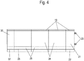
- FIG 4 an assembled core from the molded parts 21, 24 and 30 is shown.
- the molded parts 21, 24 and 30 form a recess 19 on an upper edge into which the upper web 15 with the step 16 of the metal sheet 11 can be inserted, so that the metal sheet 11 is also fixed to the core 20 in a form-fitting manner.
- FIG. 5 a further embodiment of a side frame is shown, which is similar to FIG Figure 2 is formed, but the molded parts 21, 24 and 30 have one or more openings for reinforcing elements 40 and 41.
- a first band or strip-shaped reinforcing element 40 for example made of sheet steel or a hard plastic, extends through the central molded parts 24 and has a projection 42 or a recess with a pin or bolt inserted therein, which extends into an opening 43 of the front molded part 21 and an opening 33 of the rear molding 30 is insertable.
- the band-shaped reinforcing element 40 can increase the lateral stability and the resilience of the core in tension.
- a rod-shaped reinforcing element 41 is passed through openings 29 in the molded parts 21, 24 and 30, which, for example, is glued in the openings 29. Other mechanical fixings for the reinforcement part 41 can also be provided.
- FIGS Figures 7A through 7F different variants for a sheathing of a core 20 are shown, which is only shown schematically and can be designed as shown in FIGS Figures 2 or 5 is shown.
- FIG 7A a plate-shaped metal sheet 11 'according to the invention is shown, which is glued to the core 20, and a second metal sheet 12' is bent in a U-shape in the upper region and is also glued to the core 20.
- the step 16 on the sheet metal and the bend 14 on the sheet metal have been omitted.
- the in Figure 7B The embodiment shown, not according to the invention, is formed from three parts, namely two plate-shaped metal sheets 50 and 51, which are covered in the upper area by a U-shaped profile 52, which overlaps the outer walls of the metal sheets 50 and 51 with the two legs.
- FIG. 7C a variant is shown in which the core 20 is covered by a one-piece sheath 55 which is bent in accordance with the core, a recess for the passage of the base 2 being omitted.
- the casing is formed by two metal sheets 60 and 61, which are plate-shaped on the inside and outside and are bent in a U-shape in the upper area, the leg engaging in a groove-shaped receptacle in the core 20 in the connecting area.
- the stability of the unit made up of sheath and core 20 can be increased, especially if the legs engaging in core 20 are also glued to core 20.
- Sheath 70 is again formed in one piece, similar to FIG Figure 7C , however, a bend 71 is provided above the drawer 1, which rests on the base 2 so that no gap is visible between the top of the base 2 and the envelope.
- the Figure 7F shows an embodiment of a casing with an inner wall 80 and an outer wall 81 made of angled metal sheets which surround a core 20.
- an insert part 82 is provided which can be inserted into a receptacle on the core 20 with a latching element 83, in particular a pin with a latching head.
- a latching element 83 in particular a pin with a latching head.
- the inner wall and the outer wall 81 can be fixed in the manner of a welt.
- the inner wall 80 and the outer wall 81 at least partially engage with one end portion in the receptacle on the core 20 and are fixed by the plug-in part 82 in a form-fitting or force-fitting manner.
- the core 20 can have only one reinforcement element 40 or 41 or more than the reinforcement elements 40 and 41 shown.
- the reinforcement does not have to extend through the molded parts, but can also be fixed to a surface of the molded parts, for example by gluing.
- the molded parts 21, 24 and 30 are held together in a form-fitting manner via tongue and groove connections. It is of course also possible to provide other form-fitting connections, for example dovetail connections, hook connections or other plug-in or pivot connections.
- the molded parts 21, 24 and 30 are made of plastic by injection molding. Depending on the length of the side frame, more or less central molded parts 24 can be inserted between the molded part 21 and the rear molded part 30.
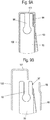
- FIG. 8A to 8C Another embodiment of a side frame 10 ′ is shown, which has a front molded part 90, a central molded part 91 and a rear molded part 92.
- the middle molded part 91 has a smaller height in the vertical longitudinal direction of the side frame than the molded parts 90 and 92.
- a wall element made of glass or another visually appealing material is placed on the middle molded part and remains visible from the outside.
- an inner casing is provided on the inside of the side frame, which has a front web 93 and a rear web 95, between which a recess 94 is formed, in which the wall element made of glass remains visible.
- the front molded part 90 and the rear molded part 92 are connected to one another via the central molded part 91, on which a groove is provided for receiving a base for the drawer.
- the web 93 covers the front molded part 90 and protrudes over it in the longitudinal direction of the frame, so that the wall element made of glass is partially covered by the web 93 and the rear web 95 and thereby the wall element 112 is held in the vertical direction to the longitudinal direction of the side frame.
- an outer casing 100 with two webs 103 and 104 is provided on the outside of the frame, which optionally also with webs 93 and 95 are connected, wherein a U-shaped edge 101 is formed on the front web 103, which overlaps an upper side of the molded part 90.
- an end section of the wall element 112 is overlapped so that the wall element 91 is held by the sheaths.
- the front molded part 90 and the rear molded part 92 are arranged in one plane with the wall element made of glass and form almost flat contact surfaces in the direction of the inner and outer casing.
- a groove 96 is formed on the upper side of the molded parts 90 and 92 and can be used for the assembly of further components, for example cover strips or attachment frames. In the embodiment of Figures 8 and 9 however, the groove 96 is not occupied.
- the molded part 90 is provided for assembly, before the inner casing with the web 93 and the outer casing 100 with the U-shaped edge 101 are fitted.
- a step-shaped edge 98 is formed, which engages in a corresponding receptacle 97 on the molded part 90, so that the inner casing with the web 93 is held in a form-fitting manner on the molded part 90.
- the stepped edge 98 is then covered by the U-shaped edge 101 of the outer casing 100, it being possible for the casings to optionally also be glued to one another.
- FIG. 10A and 10B a modified embodiment of a side frame is shown in which an inner casing 93 'has no recess 94, and a plurality of molded parts 90 are provided inside, as has already been explained above.
- an outer casing 100 is provided which, with a U-shaped edge 101, surrounds the molded parts 90 on an upper side.
- a groove 96 is recessed in the molded parts 90, into which a light guide 105 is inserted.
- Light is radiated into the light guide 105, for example via an LED which is arranged in the side frame, the rear wall or the front panel.
- Several openings 102 are recessed in the U-shaped edge 101 so that light can be emitted via the light guide 105 through the openings 102, which results in a visually appealing effect.
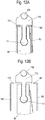
- FIG 11A and 11B is an opposite Figure 10 A modified exemplary embodiment is shown in which an insertion part 110 is inserted into the groove 96 on the molded parts 90, on the top of which a light guide 105 is arranged.
- the rod-shaped light guide 105 remains visible from the outside after assembly can serve to distribute light which is radiated into an end face of the light guide 105.
- the inner sheath 93 ′ extends to just below the light guide 105, and the outer sheath does not cover the light guide 105 either.
- the inner cover 93 ' may have a curved edge 98' at the top and the outer cover may have a curved edge 101 which are inserted between a top of the molding and a thickened head portion of the male part 110.
- the sheaths 93 'and 100' can thus be held in position via the plug-in part 110.
- the insertion part 110 has a thickened foot section 111 which is inserted into a corresponding widening of the groove 96.
- the light guide 105 is fixed, in particular glued or clamped, to the top of the plug-in part 110.
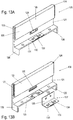
- FIG. 13A and 13B a modified molded part made of plastic for a side frame is shown, wherein the metallic casing has been omitted.
- the side frame comprises at least one molded part 120 with a groove 121 for receiving a bottom of the drawer.
- the molded parts 120 preferably extend over the entire length of the side frame.
- a wall element 122 is provided above the Nur, which has a groove 123 in the longitudinal direction of the side frame on one end face, into which a protruding tongue 124 of an adjacent molded part 120 can be inserted.
- several molded parts 120 can be inserted into one another in a form-fitting manner over the entire length of a side frame.
- An opening 125 which is used to fix a metal bracket 127, is provided in a bottom of the groove 121.
- the metal bracket 127 comprises a vertical leg 128 with mounting openings 129 which are arranged within the opening 125 in the installed position.
- a receptacle is formed, into which a second leg 130 of the metal bracket 127 is inserted.
- a claw 133 with upwardly projecting teeth is formed on the second leg 130 and is surrounded by two webs with assembly openings 134.
- the bottom of the drawer can be pushed into the groove at the edge and fixed in a force-locking manner, the claw 133 digging into the bottom on an underside of the bottom.
- the clamping forces on the claw 133 are then distributed over the horizontal leg 131, which can be supported at opposite ends by webs 126 protruding downwards.
- the top of the second leg 130 and the top of the horizontal leg 131 can be aligned essentially flush to support the floor.
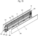
- the side frame 10 ' comprises a casing which is made of two bent metal sheets 11' and 12 'and surrounds an inner core which comprises one or more central molded parts 201, an end molded part 202 facing the front panel and an end molded part 220 facing the rear wall .
- the central molded parts 201 can be produced from plastic in an injection molding process and comprise a lattice structure, so that, based on the volume of the molded part 201, only a little material is required.
- a groove 209 for inserting an edge of a bottom of the drawer is formed on the molded parts 201, 202 and 220 under the metal sheet 12 '.
- molded parts 201, 202 and 220 On the upper side of the molded parts 201, 202 and 220 are a plurality of upwardly projecting webs 219, on which the two metal sheets 11 'and 12' of the casing can be fixed, whereby the type of fastening can also be configured according to one of the preceding exemplary embodiments .
- the molded part 202 facing the front panel is provided with a recess or receptacle into which a fastening element 203 is inserted.
- the fastening element 203 is surrounded by the molded part 202 on at least three sides, preferably on at least four sides.
- the fastening element 203 comprises an adjustment element 204 which is adjustable relative to the fastening element 203.
- Fastening means 205 for fixing the front panel are provided on the adjustment element 204, the fastening means 205 in the illustrated embodiment being designed as pins which are inserted into corresponding bores or openings on the front panel.
- a height adjustment is provided on the molded part 202, whereby a mounting part 207 can be fixed in the lower region of the molded part 202, on which a curved guide is formed which interacts with a lever 206 which, when rotated, adjusts the position of the front panel relative to the floor can.
- the molded part 202 arranged adjacent to the front panel can be constructed identically to a molded part arranged on the opposite side frame that faces the rear wall.
- the one facing the flashback Molded part 220 on the same side frame is designed with mirror symmetry to a central plane perpendicular to the longitudinal direction of the side frame.
- a modified fastening element 221 is inserted into the receptacle, which is held essentially positively on the molded part 220 and serves to fix the side frame to the rear wall.
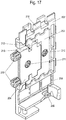
- FIG 17 the molding 202 adjacent to the front panel is shown with the fastening element 203 in detail.
- a rotatable eccentric 210 is located on the fastening element 203, which is inserted in an opening 214 on a wall section of the molded part 202 ( Figure 18 ) is rotatably mounted.
- the adjusting element 204 can be adjusted in height relative to the fastening element 203 via the eccentric 210.
- the adjusting element 204 is accommodated with vertical play within the fastening element 203, with one or more webs 212 being formed on the fastening element 203 for guidance which engage in corresponding recesses 213 or guide receptacles.
- a lateral adjustment 211 which is arranged on the adjusting element 204, is also provided on the fastening element 203.
- the position of the adjusting element 204 can be changed in a direction horizontally and perpendicular to the longitudinal direction of the side frame via the side adjustment 211.
- molded part 202 On the molded part 202 there is also a groove 209 for receiving an edge of the bottom of the drawer, wherein the position of the bottom can be changed by adjusting the height.
- the height adjustment with the lever 206 is rotatably mounted on an eyelet 208.
- FIG 18 the molded part 202 is shown without the fastening element 203, and it can be seen that the fastening element 203 is enclosed in a U-shape and at least partially rests on a fourth side on a wall section.
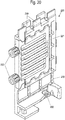
- the fastening element 203 is shown, and the eccentric 210 can be seen, by means of which the adjusting element 204 can be adjusted in height relative to the fastening element 203. Furthermore, the side adjustment 211 can be seen, which enables the adjustment element 204 to be positioned in a direction perpendicular to the plane of the side frame. Two pins are formed on the adjusting element 204 as fastening means 205 for fixing the front panel.
- the rear molded part 220 is shown, which has webs 219 on the upper edge and has a receptacle or recess which is formed as in the front molded part 202 and is only open to the rear.
- a fastening element 221 is inserted into the receptacle as a molded part, which is held in a form-fitting and immovable manner on the molded part 220.
- Two pins 222 are molded onto the fastening element 221 and serve to fix a rear wall.
- the molded part 220 further comprises a groove for receiving the edge of the base and an eyelet 208 for mounting a height adjustment.
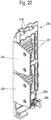
- a modified molded part 230 is shown, which is formed higher than the previously described molded parts 202 and 220, wherein two receptacles or recesses are formed in the molded part 230, into each of which a fastening element 203 is inserted.
- the two fastening elements 203 are arranged one above the other, so that the molded part 230 can be used for high side frames.
- the design of the fastening element 203 with the adjusting elements 204 adjustably held therein is designed as in the previous exemplary embodiments.
- a height adjustment with the mounting part 207 and the lever 206 is also shown, which can adjust the base relative to the molded part 230.
- FIG 23 the molded part 230 is shown with two modified fastening elements 221 ', in which, instead of a pin 205 or an angled web 224, a latching element 222' is provided in order to fix a rear wall.
- the latching elements 222 ' can, for example, be inserted into an opening on a rear wall for locking the rear wall.
- one and the same molded part 230 can be used for mounting different rear walls by using different fastening elements 203, 221 or 221 '.
- the same variations can of course also be made on the front to fix the front panel.
Landscapes
- Engineering & Computer Science (AREA)
- General Engineering & Computer Science (AREA)
- Mechanical Engineering (AREA)
- Drawers Of Furniture (AREA)
- Furniture Connections (AREA)
- Connection Of Plates (AREA)
Claims (17)
- Tiroir (1) comportant deux châssis latéraux (10), un fond (2), un dos (3) et une façade,- au moins un châssis latéral (10) comprenant une enveloppe à parois minces (11, 12) soutenue par un noyau intérieur (20),- le noyau intérieur (20) comprenant au moins deux pièces de forme (21, 24, 30, 90, 91, 92, 120, 202, 220, 230), tenues les unes aux autres par une liaison par la forme,tiroir caractérisé en ce que
au moins une pièce de forme (120) comporte une rainure (121) pour recevoir le fond du tiroir. - Tiroir selon la revendication 1,
caractérisé en ce que
le noyau intérieur (20) comporte au moins trois pièces de forme (21, 24, 30) qui sont tenues les unes aux autres par une liaison par la forme. - Tiroir selon la revendication 1 ou 2,
caractérisé en ce que
les pièces de forme (21, 24, 30, 202, 220, 230) s'étendent pratiquement sur toute la longueur de l'enveloppe (11, 12). - Tiroir selon l'une des revendications précédentes,
caractérisé en ce qu'
une première pièce de forme (21) est munie de moyens de fixation (23), notamment des broches venant en saillie pour fixer la façade. - Tiroir selon l'une des revendications précédentes,
caractérisé en ce qu'
une seconde pièce de forme (30) comporte des moyens de fixation (31) pour le dos (3). - Tiroir selon l'une des revendications précédentes,
caractérisé en ce que
les pièces de forme (21, 24, 30) sont des pièces injectées. - Tiroir selon l'une des revendications précédentes,
caractérisé en ce que
les pièces de forme (21, 24, 30) sont assemblées les unes aux autres par des liaisons à languette et rainure (26, 27). - Tiroir selon l'une des revendications précédentes,
caractérisé en ce que
l'enveloppe (11, 12) est collée aux pièces de forme (21, 24, 30). - Tiroir selon l'une des revendications précédentes,
caractérisé en ce que
les pièces de forme (21, 24, 30) sont pratiquement des plaques et ont une entretoise latéralement en saillie (22, 25) comme appui pour le fond (2). - Tiroir selon l'une des revendications précédentes,
caractérisé en ce que
l'enveloppe (11, 12) est formée d'une ou plusieurs pièces en métal, notamment en tôle d'acier, et
les tôles métalliques ont, de préférence, une épaisseur inférieure à 0,8 mm, notamment inférieure à 0,5 mm. - Tiroir selon l'une des revendications précédentes,
caractérisé en ce que
un renfort (40, 41) en une matière de forme stable, notamment en métal ou en matière plastique est prévu dans ou sur les pièces de forme (21, 24, 30). - Tiroir selon l'une des revendications précédentes,
caractérisé en ce que
les châssis latéraux (10) ont une épaisseur inférieure à 10 mm, notamment inférieure à 8 mm. - Tiroir selon l'une des revendications précédentes,
caractérisé en ce que
l'enveloppe (11, 12) comporte au moins en partie des éléments de décor en bois. - Tiroir selon l'une quelconque des revendications précédentes, caractérisé en ce que
le noyau intérieur comprend au moins deux pièces de forme (90, 91) ayant des hauteurs différentes dans la direction verticale par rapport à la direction longitudinale des châssis latéraux. - Tiroir selon l'une des revendications précédentes,
caractérisé en ce qu'
un guide de lumière ou un moyen d'éclairage (105) est prévu sur ou dans les pièces de forme du châssis latéral. - Tiroir selon l'une quelconque des revendications précédentes, caractérisé en ce qu'
un logement avec une griffe (133) en métal est prévu dans un logement pour la fixation du fond. - Tiroir selon l'une quelconque des revendications précédentes, caractérisé en ce qu'
une pièce de forme (202, 220, 230) prévue en extrémité au voisinage de la façade ou du dos (3) comporte un logement dans lequel s'engage un élément de fixation (203, 221, 221') pour fixer la façade ou le dos (3) à la pièce de forme d'extrémité (202, 220, 230),
* l'élément de fixation (203, 221, 221') étant monté coulissant ou pivotant de préférence par rapport à la pièce de forme (202, 220, 230) par l'intermédiaire d'un mécanisme de réglage (206, 210, 221).
Applications Claiming Priority (3)
| Application Number | Priority Date | Filing Date | Title |
|---|---|---|---|
| DE102016122824 | 2016-11-25 | ||
| DE102017121597.2A DE102017121597A1 (de) | 2016-11-25 | 2017-09-18 | Schubkasten |
| PCT/EP2017/079642 WO2018095820A1 (fr) | 2016-11-25 | 2017-11-17 | Tiroir |
Publications (2)
| Publication Number | Publication Date |
|---|---|
| EP3544467A1 EP3544467A1 (fr) | 2019-10-02 |
| EP3544467B1 true EP3544467B1 (fr) | 2020-09-16 |
Family
ID=62117381
Family Applications (1)
| Application Number | Title | Priority Date | Filing Date |
|---|---|---|---|
| EP17800543.5A Active EP3544467B1 (fr) | 2016-11-25 | 2017-11-17 | Tiroir |
Country Status (8)
| Country | Link |
|---|---|
| US (1) | US10729242B2 (fr) |
| EP (1) | EP3544467B1 (fr) |
| JP (1) | JP7044779B2 (fr) |
| KR (1) | KR102433108B1 (fr) |
| CN (1) | CN109922695B (fr) |
| DE (1) | DE102017121597A1 (fr) |
| ES (1) | ES2832712T3 (fr) |
| WO (1) | WO2018095820A1 (fr) |
Cited By (1)
| Publication number | Priority date | Publication date | Assignee | Title |
|---|---|---|---|---|
| DE102021115892A1 (de) | 2021-06-18 | 2022-12-22 | Paul Hettich Gmbh & Co. Kg | Verstellvorrichtung für einen Schubkasten |
Families Citing this family (16)
| Publication number | Priority date | Publication date | Assignee | Title |
|---|---|---|---|---|
| DE102018123054A1 (de) * | 2018-09-19 | 2020-03-19 | Paul Hettich Gmbh & Co. Kg | Schubkasten und Einheit aus einer Auszugsführung und einem Schubkasten |
| DE102019106308A1 (de) * | 2019-03-12 | 2020-09-17 | Paul Hettich Gmbh & Co. Kg | Schubkasten |
| DE102019111861A1 (de) * | 2019-05-07 | 2020-11-12 | Paul Hettich Gmbh & Co. Kg | Schubkastenwandelement |
| USD938212S1 (en) * | 2019-05-16 | 2021-12-14 | Julius Blum Gmbh | Furniture drawer |
| DE102019113101A1 (de) * | 2019-05-17 | 2020-11-19 | Paul Hettich Gmbh & Co. Kg | Seitenzarge für einen Schubkasten |
| DE102019113102A1 (de) * | 2019-05-17 | 2020-11-19 | Paul Hettich Gmbh & Co. Kg | Schubkastenwand |
| AT522842B1 (de) * | 2019-07-18 | 2023-11-15 | Blum Gmbh Julius | Schubladenrückwand |
| DE102019122854A1 (de) * | 2019-08-26 | 2021-03-04 | Paul Hettich Gmbh & Co. Kg | Seitenzarge |
| DE102020119901A1 (de) * | 2020-07-28 | 2022-02-03 | Paul Hettich Gmbh & Co. Kg | Adaptereinheit zur Verbindung eines Schubkastenbodens mit einer Seitenzarge eines Schubkastens, Seitenzarge und Schubkasten |
| DE102020126359A1 (de) | 2020-10-08 | 2022-04-14 | Grass Gmbh | Schubladenwandelement für eine Schublade |
| AT524493B1 (de) * | 2020-12-02 | 2024-10-15 | Blum Gmbh Julius | Verfahren zur manuellen und/oder maschinellen Herstellung einer doppelwandigen Schubladenzarge |
| DE102021102667B4 (de) * | 2021-02-04 | 2023-12-07 | Paul Hettich Gmbh & Co. Kg | Schubelement mit einer Beleuchtungseinrichtung und Möbel mit einem solchen Schubelement |
| CN113017315B (zh) * | 2021-03-25 | 2022-10-14 | 东莞市大境华家具发展有限公司 | 木饰面板阴角连接结构、其成型工艺及具有该结构的木柜 |
| AT525777B1 (de) * | 2021-12-21 | 2025-06-15 | Blum Gmbh Julius | Doppelwandige Schubladenzarge |
| CN117432693A (zh) * | 2022-07-12 | 2024-01-23 | 川湖科技股份有限公司 | 家具及其家具组件 |
| DE102023130069A1 (de) * | 2023-10-31 | 2025-04-30 | Paul Hettich Gmbh & Co. Kg | Seitenzarge und Schubkasten |
Family Cites Families (27)
| Publication number | Priority date | Publication date | Assignee | Title |
|---|---|---|---|---|
| GB1189907A (en) * | 1967-10-16 | 1970-04-29 | Leslie William Llewelly Alston | Improvements in or relating to Drawers for Furniture |
| JPS4916483Y1 (fr) * | 1968-10-03 | 1974-04-25 | ||
| US3791002A (en) * | 1972-07-31 | 1974-02-12 | Armstrong Cork Co | Method of making a thermoplastic drawer |
| US4440460A (en) * | 1981-08-06 | 1984-04-03 | Brighoff John C | Furniture and drawer therefor |
| CN2164727Y (zh) * | 1993-02-23 | 1994-05-18 | 陈安男 | 组装式桌柜 |
| CN2225803Y (zh) * | 1995-07-10 | 1996-05-01 | 郑永胜 | 可伸展组装的抽屉 |
| US5597221A (en) * | 1995-11-01 | 1997-01-28 | Sauder Woodworking Co. | Drawer assembly having interlocking members |
| US5678509A (en) * | 1995-11-08 | 1997-10-21 | Dillon; Charles E. | All-in-one litter box, sleeping area, and food and water bowl system useable as a pet carrier |
| JP2919784B2 (ja) * | 1996-07-18 | 1999-07-19 | ナショナル住宅産業株式会社 | 壁状収納装置 |
| AT407332B (de) * | 1997-03-21 | 2001-02-26 | Blum Gmbh Julius | Schublade |
| AT409069B (de) * | 1997-07-03 | 2002-05-27 | Blum Gmbh Julius | Schubladenzarge |
| DE202005008286U1 (de) * | 2005-05-27 | 2006-10-05 | Paul Hettich Gmbh & Co. Kg | Schubkasten |
| DE202007001780U1 (de) | 2006-09-08 | 2008-01-10 | Paul Hettich Gmbh & Co. Kg | Schubkasten |
| GB2437060A (en) * | 2006-12-19 | 2007-10-17 | Crystal Clear Internat Ltd | Cosmetic lotion dispenser with massager |
| CN100450397C (zh) * | 2007-01-15 | 2009-01-14 | 谷丽华 | 金属橱柜面板及其制作方法 |
| DE202007002791U1 (de) * | 2007-02-22 | 2008-06-26 | Rudolf Henrichsmeyer Formaplan Gmbh & Co. Kg | Möbelbauteil |
| DE202009005203U1 (de) * | 2008-10-23 | 2010-03-04 | Paul Hettich Gmbh & Co. Kg | Schubkasten und Werkzeug zum Festklemmen eines Schubkastenbodens |
| CN101824953A (zh) * | 2010-05-13 | 2010-09-08 | 佛山市顺德区安博基业电子器械有限公司 | 一种玻璃门体 |
| US20130181590A1 (en) * | 2012-01-18 | 2013-07-18 | Shun-Teng Chen | Combination Drawer |
| CN202723064U (zh) * | 2012-05-14 | 2013-02-13 | 伍兴 | 组合储物柜 |
| DE202013011425U1 (de) * | 2013-12-20 | 2015-03-23 | Grass Gmbh | Schubladenwandelement und Füllelement für eine Schubladenwand sowie Möbel |
| DE102014000822A1 (de) | 2014-01-22 | 2015-07-23 | Grass Gmbh | Verfahren zur Herstellung eines Möbelteils |
| CN204091381U (zh) * | 2014-06-27 | 2015-01-14 | 周波 | 衣柜及其板体集成件 |
| DE102015109459A1 (de) * | 2015-05-05 | 2016-11-10 | Form Orange Produktentwicklung | Schublade mit einer Bodenplatte, zwei Seitenwänden, einer Rückwand und einer Bodenplatte |
| FR3036269B1 (fr) * | 2015-05-21 | 2017-07-07 | Paperflow | Meuble de rangement comportant une cassette renfermant un rideau deformable de fermeture |
| DE202015102912U1 (de) * | 2015-06-05 | 2016-09-06 | Grass Gmbh | Wandelement für eine Schublade, Schublade und Möbel mit einer Schublade |
| CN205493083U (zh) * | 2016-03-24 | 2016-08-24 | 陈进 | 一种组装式简易柜子 |
-
2017
- 2017-09-18 DE DE102017121597.2A patent/DE102017121597A1/de not_active Withdrawn
- 2017-11-17 KR KR1020197011304A patent/KR102433108B1/ko active Active
- 2017-11-17 US US16/463,453 patent/US10729242B2/en active Active
- 2017-11-17 EP EP17800543.5A patent/EP3544467B1/fr active Active
- 2017-11-17 ES ES17800543T patent/ES2832712T3/es active Active
- 2017-11-17 CN CN201780068993.8A patent/CN109922695B/zh active Active
- 2017-11-17 WO PCT/EP2017/079642 patent/WO2018095820A1/fr not_active Ceased
- 2017-11-17 JP JP2019528116A patent/JP7044779B2/ja active Active
Non-Patent Citations (1)
| Title |
|---|
| None * |
Cited By (2)
| Publication number | Priority date | Publication date | Assignee | Title |
|---|---|---|---|---|
| DE102021115892A1 (de) | 2021-06-18 | 2022-12-22 | Paul Hettich Gmbh & Co. Kg | Verstellvorrichtung für einen Schubkasten |
| WO2022263444A1 (fr) | 2021-06-18 | 2022-12-22 | Paul Hettich Gmbh & Co. Kg | Dispositif de réglage pour tiroir |
Also Published As
| Publication number | Publication date |
|---|---|
| KR102433108B1 (ko) | 2022-08-16 |
| JP7044779B2 (ja) | 2022-03-30 |
| KR20190088968A (ko) | 2019-07-29 |
| CN109922695A (zh) | 2019-06-21 |
| DE102017121597A1 (de) | 2018-05-30 |
| CN109922695B (zh) | 2021-03-30 |
| US20190357678A1 (en) | 2019-11-28 |
| WO2018095820A1 (fr) | 2018-05-31 |
| ES2832712T3 (es) | 2021-06-11 |
| US10729242B2 (en) | 2020-08-04 |
| EP3544467A1 (fr) | 2019-10-02 |
| JP2020513261A (ja) | 2020-05-14 |
Similar Documents
| Publication | Publication Date | Title |
|---|---|---|
| WO2018095820A1 (fr) | Tiroir | |
| EP2238871B1 (fr) | Système de fabrication d'une paroi multifonction pouvant être montée sur un mur, notamment le mur d'une pièce et procédé de fabrication et de montage d'une paroi multifonction | |
| EP3496570B1 (fr) | Châssis destiné à un tiroir | |
| EP0551575A1 (fr) | Face latérale d'un tiroir | |
| EP3009045A1 (fr) | Chassis pour tiroir dote d'un corps de chassis et tiroir et meuble equipe d'un tiroir | |
| DE102008005067A1 (de) | Wandelement, Modul und modulares Regalsystem | |
| DE2610998B2 (de) | Halterung zur Befestigung von Bekleidungsplatten vor einer Bauwerkswand | |
| AT509484B1 (de) | Haltevorrichtung zum verbinden von profilen zu einem flächigen wandelement | |
| DE2625202B2 (de) | Haushaltgerät z.B. Geschirrspülmaschine mit einem frontseitigen Sockelrücksprung | |
| EP1426520A1 (fr) | Dispositif de fixation pour panneaux et procédé pour la fixation d'un panneau | |
| EP3009044A1 (fr) | Element mural pour chassis et chassis, tiroir et meuble | |
| EP3968819B1 (fr) | Glissière latérale pour un tiroir | |
| DE10242519B4 (de) | Schublade oder dergleichen | |
| DE9205273U1 (de) | Befestigungselement zur verdeckten Halterung | |
| AT394617B (de) | Fenstersprossensystem aus hohlprofilen und deren verbindungen | |
| DE202007001060U1 (de) | Modulares Wandregal | |
| DE29516689U1 (de) | Bauelemente für Gestelle, Wandkonstruktionen o.dgl. | |
| DE2852618C2 (de) | "Leuchte zum Einbau in vorgefertigte Zwischendecken | |
| DE102025125478A1 (de) | Element für eine modulare Treppenwange | |
| EP1344880A2 (fr) | Elément de construction profilé à usage en tant qu'élément de clôture | |
| DE29821761U1 (de) | Verkleidungssystem für eine Wanne, vorzugsweise Badewanne | |
| DE29515467U1 (de) | Regal | |
| DE29916580U1 (de) | Bausatz für Metallbox | |
| DE4405312A1 (de) | Badewannensitz | |
| DE3242217A1 (de) | Vorgefertigte tuerrahmenanordnung |
Legal Events
| Date | Code | Title | Description |
|---|---|---|---|
| STAA | Information on the status of an ep patent application or granted ep patent |
Free format text: STATUS: UNKNOWN |
|
| STAA | Information on the status of an ep patent application or granted ep patent |
Free format text: STATUS: THE INTERNATIONAL PUBLICATION HAS BEEN MADE |
|
| PUAI | Public reference made under article 153(3) epc to a published international application that has entered the european phase |
Free format text: ORIGINAL CODE: 0009012 |
|
| STAA | Information on the status of an ep patent application or granted ep patent |
Free format text: STATUS: REQUEST FOR EXAMINATION WAS MADE |
|
| 17P | Request for examination filed |
Effective date: 20190531 |
|
| AK | Designated contracting states |
Kind code of ref document: A1 Designated state(s): AL AT BE BG CH CY CZ DE DK EE ES FI FR GB GR HR HU IE IS IT LI LT LU LV MC MK MT NL NO PL PT RO RS SE SI SK SM TR |
|
| AX | Request for extension of the european patent |
Extension state: BA ME |
|
| DAV | Request for validation of the european patent (deleted) | ||
| DAX | Request for extension of the european patent (deleted) | ||
| GRAP | Despatch of communication of intention to grant a patent |
Free format text: ORIGINAL CODE: EPIDOSNIGR1 |
|
| STAA | Information on the status of an ep patent application or granted ep patent |
Free format text: STATUS: GRANT OF PATENT IS INTENDED |
|
| INTG | Intention to grant announced |
Effective date: 20200608 |
|
| RIN1 | Information on inventor provided before grant (corrected) |
Inventor name: STAUFENBERG, GERRIT Inventor name: BEUMLER, SOEREN Inventor name: MERTINS, STEFAN Inventor name: SZLAPKA, TIMO |
|
| GRAS | Grant fee paid |
Free format text: ORIGINAL CODE: EPIDOSNIGR3 |
|
| GRAA | (expected) grant |
Free format text: ORIGINAL CODE: 0009210 |
|
| STAA | Information on the status of an ep patent application or granted ep patent |
Free format text: STATUS: THE PATENT HAS BEEN GRANTED |
|
| AK | Designated contracting states |
Kind code of ref document: B1 Designated state(s): AL AT BE BG CH CY CZ DE DK EE ES FI FR GB GR HR HU IE IS IT LI LT LU LV MC MK MT NL NO PL PT RO RS SE SI SK SM TR |
|
| REG | Reference to a national code |
Ref country code: GB Ref legal event code: FG4D Free format text: NOT ENGLISH |
|
| REG | Reference to a national code |
Ref country code: CH Ref legal event code: EP |
|
| REG | Reference to a national code |
Ref country code: DE Ref legal event code: R096 Ref document number: 502017007337 Country of ref document: DE |
|
| REG | Reference to a national code |
Ref country code: IE Ref legal event code: FG4D Free format text: LANGUAGE OF EP DOCUMENT: GERMAN |
|
| REG | Reference to a national code |
Ref country code: AT Ref legal event code: REF Ref document number: 1313332 Country of ref document: AT Kind code of ref document: T Effective date: 20201015 |
|
| PG25 | Lapsed in a contracting state [announced via postgrant information from national office to epo] |
Ref country code: FI Free format text: LAPSE BECAUSE OF FAILURE TO SUBMIT A TRANSLATION OF THE DESCRIPTION OR TO PAY THE FEE WITHIN THE PRESCRIBED TIME-LIMIT Effective date: 20200916 Ref country code: HR Free format text: LAPSE BECAUSE OF FAILURE TO SUBMIT A TRANSLATION OF THE DESCRIPTION OR TO PAY THE FEE WITHIN THE PRESCRIBED TIME-LIMIT Effective date: 20200916 Ref country code: SE Free format text: LAPSE BECAUSE OF FAILURE TO SUBMIT A TRANSLATION OF THE DESCRIPTION OR TO PAY THE FEE WITHIN THE PRESCRIBED TIME-LIMIT Effective date: 20200916 Ref country code: BG Free format text: LAPSE BECAUSE OF FAILURE TO SUBMIT A TRANSLATION OF THE DESCRIPTION OR TO PAY THE FEE WITHIN THE PRESCRIBED TIME-LIMIT Effective date: 20201216 Ref country code: GR Free format text: LAPSE BECAUSE OF FAILURE TO SUBMIT A TRANSLATION OF THE DESCRIPTION OR TO PAY THE FEE WITHIN THE PRESCRIBED TIME-LIMIT Effective date: 20201217 Ref country code: NO Free format text: LAPSE BECAUSE OF FAILURE TO SUBMIT A TRANSLATION OF THE DESCRIPTION OR TO PAY THE FEE WITHIN THE PRESCRIBED TIME-LIMIT Effective date: 20201216 |
|
| REG | Reference to a national code |
Ref country code: NL Ref legal event code: MP Effective date: 20200916 |
|
| PG25 | Lapsed in a contracting state [announced via postgrant information from national office to epo] |
Ref country code: RS Free format text: LAPSE BECAUSE OF FAILURE TO SUBMIT A TRANSLATION OF THE DESCRIPTION OR TO PAY THE FEE WITHIN THE PRESCRIBED TIME-LIMIT Effective date: 20200916 Ref country code: LV Free format text: LAPSE BECAUSE OF FAILURE TO SUBMIT A TRANSLATION OF THE DESCRIPTION OR TO PAY THE FEE WITHIN THE PRESCRIBED TIME-LIMIT Effective date: 20200916 |
|
| REG | Reference to a national code |
Ref country code: LT Ref legal event code: MG4D |
|
| PG25 | Lapsed in a contracting state [announced via postgrant information from national office to epo] |
Ref country code: LT Free format text: LAPSE BECAUSE OF FAILURE TO SUBMIT A TRANSLATION OF THE DESCRIPTION OR TO PAY THE FEE WITHIN THE PRESCRIBED TIME-LIMIT Effective date: 20200916 Ref country code: SM Free format text: LAPSE BECAUSE OF FAILURE TO SUBMIT A TRANSLATION OF THE DESCRIPTION OR TO PAY THE FEE WITHIN THE PRESCRIBED TIME-LIMIT Effective date: 20200916 Ref country code: EE Free format text: LAPSE BECAUSE OF FAILURE TO SUBMIT A TRANSLATION OF THE DESCRIPTION OR TO PAY THE FEE WITHIN THE PRESCRIBED TIME-LIMIT Effective date: 20200916 Ref country code: RO Free format text: LAPSE BECAUSE OF FAILURE TO SUBMIT A TRANSLATION OF THE DESCRIPTION OR TO PAY THE FEE WITHIN THE PRESCRIBED TIME-LIMIT Effective date: 20200916 Ref country code: PT Free format text: LAPSE BECAUSE OF FAILURE TO SUBMIT A TRANSLATION OF THE DESCRIPTION OR TO PAY THE FEE WITHIN THE PRESCRIBED TIME-LIMIT Effective date: 20210118 Ref country code: CZ Free format text: LAPSE BECAUSE OF FAILURE TO SUBMIT A TRANSLATION OF THE DESCRIPTION OR TO PAY THE FEE WITHIN THE PRESCRIBED TIME-LIMIT Effective date: 20200916 |
|
| PG25 | Lapsed in a contracting state [announced via postgrant information from national office to epo] |
Ref country code: PL Free format text: LAPSE BECAUSE OF FAILURE TO SUBMIT A TRANSLATION OF THE DESCRIPTION OR TO PAY THE FEE WITHIN THE PRESCRIBED TIME-LIMIT Effective date: 20200916 Ref country code: IS Free format text: LAPSE BECAUSE OF FAILURE TO SUBMIT A TRANSLATION OF THE DESCRIPTION OR TO PAY THE FEE WITHIN THE PRESCRIBED TIME-LIMIT Effective date: 20210116 Ref country code: AL Free format text: LAPSE BECAUSE OF FAILURE TO SUBMIT A TRANSLATION OF THE DESCRIPTION OR TO PAY THE FEE WITHIN THE PRESCRIBED TIME-LIMIT Effective date: 20200916 |
|
| REG | Reference to a national code |
Ref country code: ES Ref legal event code: FG2A Ref document number: 2832712 Country of ref document: ES Kind code of ref document: T3 Effective date: 20210611 |
|
| REG | Reference to a national code |
Ref country code: DE Ref legal event code: R097 Ref document number: 502017007337 Country of ref document: DE |
|
| PG25 | Lapsed in a contracting state [announced via postgrant information from national office to epo] |
Ref country code: MC Free format text: LAPSE BECAUSE OF FAILURE TO SUBMIT A TRANSLATION OF THE DESCRIPTION OR TO PAY THE FEE WITHIN THE PRESCRIBED TIME-LIMIT Effective date: 20200916 Ref country code: SK Free format text: LAPSE BECAUSE OF FAILURE TO SUBMIT A TRANSLATION OF THE DESCRIPTION OR TO PAY THE FEE WITHIN THE PRESCRIBED TIME-LIMIT Effective date: 20200916 |
|
| REG | Reference to a national code |
Ref country code: CH Ref legal event code: PL |
|
| PLBE | No opposition filed within time limit |
Free format text: ORIGINAL CODE: 0009261 |
|
| STAA | Information on the status of an ep patent application or granted ep patent |
Free format text: STATUS: NO OPPOSITION FILED WITHIN TIME LIMIT |
|
| PG25 | Lapsed in a contracting state [announced via postgrant information from national office to epo] |
Ref country code: LU Free format text: LAPSE BECAUSE OF NON-PAYMENT OF DUE FEES Effective date: 20201117 |
|
| REG | Reference to a national code |
Ref country code: BE Ref legal event code: MM Effective date: 20201130 |
|
| 26N | No opposition filed |
Effective date: 20210617 |
|
| PG25 | Lapsed in a contracting state [announced via postgrant information from national office to epo] |
Ref country code: CH Free format text: LAPSE BECAUSE OF NON-PAYMENT OF DUE FEES Effective date: 20201130 Ref country code: SI Free format text: LAPSE BECAUSE OF FAILURE TO SUBMIT A TRANSLATION OF THE DESCRIPTION OR TO PAY THE FEE WITHIN THE PRESCRIBED TIME-LIMIT Effective date: 20200916 Ref country code: DK Free format text: LAPSE BECAUSE OF FAILURE TO SUBMIT A TRANSLATION OF THE DESCRIPTION OR TO PAY THE FEE WITHIN THE PRESCRIBED TIME-LIMIT Effective date: 20200916 Ref country code: LI Free format text: LAPSE BECAUSE OF NON-PAYMENT OF DUE FEES Effective date: 20201130 |
|
| PG25 | Lapsed in a contracting state [announced via postgrant information from national office to epo] |
Ref country code: IE Free format text: LAPSE BECAUSE OF NON-PAYMENT OF DUE FEES Effective date: 20201117 |
|
| PGFP | Annual fee paid to national office [announced via postgrant information from national office to epo] |
Ref country code: FR Payment date: 20211119 Year of fee payment: 5 |
|
| PG25 | Lapsed in a contracting state [announced via postgrant information from national office to epo] |
Ref country code: MT Free format text: LAPSE BECAUSE OF FAILURE TO SUBMIT A TRANSLATION OF THE DESCRIPTION OR TO PAY THE FEE WITHIN THE PRESCRIBED TIME-LIMIT Effective date: 20200916 Ref country code: CY Free format text: LAPSE BECAUSE OF FAILURE TO SUBMIT A TRANSLATION OF THE DESCRIPTION OR TO PAY THE FEE WITHIN THE PRESCRIBED TIME-LIMIT Effective date: 20200916 |
|
| PG25 | Lapsed in a contracting state [announced via postgrant information from national office to epo] |
Ref country code: MK Free format text: LAPSE BECAUSE OF FAILURE TO SUBMIT A TRANSLATION OF THE DESCRIPTION OR TO PAY THE FEE WITHIN THE PRESCRIBED TIME-LIMIT Effective date: 20200916 |
|
| GBPC | Gb: european patent ceased through non-payment of renewal fee |
Effective date: 20211117 |
|
| PG25 | Lapsed in a contracting state [announced via postgrant information from national office to epo] |
Ref country code: BE Free format text: LAPSE BECAUSE OF NON-PAYMENT OF DUE FEES Effective date: 20201130 |
|
| PG25 | Lapsed in a contracting state [announced via postgrant information from national office to epo] |
Ref country code: GB Free format text: LAPSE BECAUSE OF NON-PAYMENT OF DUE FEES Effective date: 20211117 |
|
| P01 | Opt-out of the competence of the unified patent court (upc) registered |
Effective date: 20230501 |
|
| PG25 | Lapsed in a contracting state [announced via postgrant information from national office to epo] |
Ref country code: NL Free format text: LAPSE BECAUSE OF NON-PAYMENT OF DUE FEES Effective date: 20200923 |
|
| PG25 | Lapsed in a contracting state [announced via postgrant information from national office to epo] |
Ref country code: FR Free format text: LAPSE BECAUSE OF NON-PAYMENT OF DUE FEES Effective date: 20221130 |
|
| PGFP | Annual fee paid to national office [announced via postgrant information from national office to epo] |
Ref country code: DE Payment date: 20251118 Year of fee payment: 9 |
|
| PGFP | Annual fee paid to national office [announced via postgrant information from national office to epo] |
Ref country code: AT Payment date: 20251117 Year of fee payment: 9 |
|
| PGFP | Annual fee paid to national office [announced via postgrant information from national office to epo] |
Ref country code: IT Payment date: 20251128 Year of fee payment: 9 |
|
| PGFP | Annual fee paid to national office [announced via postgrant information from national office to epo] |
Ref country code: TR Payment date: 20251113 Year of fee payment: 9 |
|
| PGFP | Annual fee paid to national office [announced via postgrant information from national office to epo] |
Ref country code: ES Payment date: 20251216 Year of fee payment: 9 |