EP3539697A1 - Element zur formung einer aufgebauten kante und verfahren zur formung einer aufgebauten kante - Google Patents
Element zur formung einer aufgebauten kante und verfahren zur formung einer aufgebauten kante Download PDFInfo
- Publication number
- EP3539697A1 EP3539697A1 EP17869893.2A EP17869893A EP3539697A1 EP 3539697 A1 EP3539697 A1 EP 3539697A1 EP 17869893 A EP17869893 A EP 17869893A EP 3539697 A1 EP3539697 A1 EP 3539697A1
- Authority
- EP
- European Patent Office
- Prior art keywords
- built
- molecular weight
- edge formation
- edge
- cutting
- Prior art date
- Legal status (The legal status is an assumption and is not a legal conclusion. Google has not performed a legal analysis and makes no representation as to the accuracy of the status listed.)
- Granted
Links
Images


Classifications
-
- B—PERFORMING OPERATIONS; TRANSPORTING
- B23—MACHINE TOOLS; METAL-WORKING NOT OTHERWISE PROVIDED FOR
- B23B—TURNING; BORING
- B23B35/00—Methods for boring or drilling, or for working essentially requiring the use of boring or drilling machines; Use of auxiliary equipment in connection with such methods
-
- B—PERFORMING OPERATIONS; TRANSPORTING
- B23—MACHINE TOOLS; METAL-WORKING NOT OTHERWISE PROVIDED FOR
- B23B—TURNING; BORING
- B23B51/00—Tools for drilling machines
- B23B51/06—Drills with lubricating or cooling equipment
-
- B—PERFORMING OPERATIONS; TRANSPORTING
- B23—MACHINE TOOLS; METAL-WORKING NOT OTHERWISE PROVIDED FOR
- B23C—MILLING
- B23C3/00—Milling particular work; Special milling operations; Machines therefor
-
- B—PERFORMING OPERATIONS; TRANSPORTING
- B23—MACHINE TOOLS; METAL-WORKING NOT OTHERWISE PROVIDED FOR
- B23P—METAL-WORKING NOT OTHERWISE PROVIDED FOR; COMBINED OPERATIONS; UNIVERSAL MACHINE TOOLS
- B23P15/00—Making specific metal objects by operations not covered by a single other subclass or a group in this subclass
- B23P15/28—Making specific metal objects by operations not covered by a single other subclass or a group in this subclass cutting tools
-
- B—PERFORMING OPERATIONS; TRANSPORTING
- B26—HAND CUTTING TOOLS; CUTTING; SEVERING
- B26F—PERFORATING; PUNCHING; CUTTING-OUT; STAMPING-OUT; SEVERING BY MEANS OTHER THAN CUTTING
- B26F1/00—Perforating; Punching; Cutting-out; Stamping-out; Apparatus therefor
- B26F1/16—Perforating by tool or tools of the drill type
-
- B—PERFORMING OPERATIONS; TRANSPORTING
- B23—MACHINE TOOLS; METAL-WORKING NOT OTHERWISE PROVIDED FOR
- B23B—TURNING; BORING
- B23B2226/00—Materials of tools or workpieces not comprising a metal
- B23B2226/27—Composites
- B23B2226/275—Carbon fibre reinforced carbon composites
-
- B—PERFORMING OPERATIONS; TRANSPORTING
- B23—MACHINE TOOLS; METAL-WORKING NOT OTHERWISE PROVIDED FOR
- B23B—TURNING; BORING
- B23B2226/00—Materials of tools or workpieces not comprising a metal
- B23B2226/61—Plastics not otherwise provided for, e.g. nylon
-
- B—PERFORMING OPERATIONS; TRANSPORTING
- B23—MACHINE TOOLS; METAL-WORKING NOT OTHERWISE PROVIDED FOR
- B23B—TURNING; BORING
- B23B2228/00—Properties of materials of tools or workpieces, materials of tools or workpieces applied in a specific manner
- B23B2228/52—Solid lubricants
-
- B—PERFORMING OPERATIONS; TRANSPORTING
- B23—MACHINE TOOLS; METAL-WORKING NOT OTHERWISE PROVIDED FOR
- B23C—MILLING
- B23C2226/00—Materials of tools or workpieces not comprising a metal
- B23C2226/27—Composites, e.g. fibre reinforced composites
-
- B—PERFORMING OPERATIONS; TRANSPORTING
- B23—MACHINE TOOLS; METAL-WORKING NOT OTHERWISE PROVIDED FOR
- B23C—MILLING
- B23C2226/00—Materials of tools or workpieces not comprising a metal
- B23C2226/61—Plastics not otherwise provided for, e.g. nylon
-
- B—PERFORMING OPERATIONS; TRANSPORTING
- B23—MACHINE TOOLS; METAL-WORKING NOT OTHERWISE PROVIDED FOR
- B23C—MILLING
- B23C5/00—Milling-cutters
- B23C5/28—Features relating to lubricating or cooling
Definitions
- the present invention relates to a material for built up edge formation and a built up edge formation method.
- Fiber reinforced composite materials typified by fiber reinforced plastics (FRP), in particular, carbon fiber reinforced plastics (CFRP), have large tensile strength and tensile elastic force and small density, as compared with glass fiber reinforced plastics (GFRP), aramid fiber reinforced plastics (AFRP), or stainless steel (SUS), and have therefore tended to be frequently used as outer panels or the like of aircrafts or vehicles in recent years.
- CFRP refers to plastics prepared by hot molding or hot press molding one or two or more layers of prepregs containing carbon fiber impregnated with a matrix resin. A material formed from this CFRP is fixed to a structure using a fastening factor such as a bolt or a rivet. Therefore, cutting work, in particular, cutting work to make many holes for passing a fastening factor in CFRP, is necessary for fixing CFRP to a structure such as an aircraft part.
- Some techniques have already been proposed in order to obtain high quality holes by the cutting work of CFRP. Examples of such a technique include a method which involves gradually changing the shape of a tool, for example, the curvature of a cutting face or the point angle of a drill (see, for example, Patent Literature 1).
- Materials for the bodywork structures (structural materials) of aircrafts are composed mainly of metal materials, most of which are occupied by aluminum alloy.
- Heat resistant alloy such as titanium alloy or stainless steel is used in a site capable of becoming a higher temperature, for example, a jet exhaust site or the neighborhood of an afterburner, in a bodywork structure. If the speed up of aircrafts will progress in the future, the strength of conventional aluminum alloy will be reduced due to aerodynamic heating. Therefore, it is expected that harder titanium alloy or stainless steel will be used as main structural materials for bodywork structures.
- These structural materials constituting the bodyworks of aircrafts need to undergo drilling work with a drill for bolting metal materials or a metal material with another structural material such as CFRP.
- a titanium alloy material is a difficult-to-cut material and therefore shortens a drill lifespan very much.
- a processing method which involves spraying a cutting oil and a method which involves changing the shape of a drill to thereby reduce load to the drill and circumvent reduction in the lifespan of the drill are listed (see, for example, Patent Literature 2).
- Cutting work of fiber reinforced composite materials is typically performed using a drill.
- the drill In the general drilling with a drill, the drill has an exceedingly short lifespan, and the drill bit suffers abrasion with increase in the number of processed holes, resulting in reduction in the quality of processed holes.
- the processed holes are more likely to have a small inside diameter, and the splintering of carbon fiber (which is a phenomenon in which a part of fiber constituting a fiber reinforced composite material remains as burrs around processed holes without being cut off) occurs easily at the exit portion of drill penetration.
- peeling between layers of prepregs constituting a fiber reinforced composite material hereinafter, referred to as "delamination" also occurs easily.
- each processed hole has a nonuniform inside diameter due to the abrasion of a drill bit, and delamination may occur from the irregularity of the processed hole. Such a phenomenon is accepted as a serious defect.
- the abrasion of a drill bit is likely to cause problems associated with the quality of processed holes.
- the production of structures using CFRP for aircrafts particularly requires high quality cutting work.
- it is very important to solve the problems described above, such as splintering and delamination.
- the cutting work of metals is typically performed using a drill. Even if a drill dedicated to metals is used, the drill has a short lifespan. In the case of using a general drill, the drill has an exceedingly short lifespan. Furthermore, the drill bit suffers abrasion with increase in the number of processed holes, resulting in reduction in the quality of processed holes. Specifically, the processed holes are more likely to have a small inside diameter, and burrs also occur easily at the exit portion of drill penetration. In addition, the abrasion of the drill may create the space between a metal material and another structural material (e.g., CFRP) to be bolted. Thus, uplift may arise between these structural materials, or scraps may enter the created space. Such a phenomenon is accepted as a serious defect.
- CFRP CFRP
- the present invention has been made in light of the problems described above, and an object of the present invention is to provide a material for built up edge formation which can reduce the abrasion of the cutting edge of a cutting tool in the cutting work of a workpiece material (particularly, a difficult-to-cut material), and a built up edge formation method using the material for built up edge formation.
- the "difficult-to-cut material” refers to a fiber reinforced composite material, a difficult-to-cut metal material, or a composite material of the fiber reinforced composite material and the difficult-to-cut metal material.
- the present inventors have conducted diligent studies to attain the object. As a result, the present inventors have completed the present invention by finding that the object can be attained by a material for built up edge formation comprising a resin block containing a high molecular weight compound (A), a medium molecular weight compound (B), and a carbon (C) having a predetermined average particle size.
- a material for built up edge formation comprising a resin block containing a high molecular weight compound (A), a medium molecular weight compound (B), and a carbon (C) having a predetermined average particle size.
- the present invention is as follows:
- the present invention can provide a material for built up edge formation which can reduce the abrasion of the cutting edge of a cutting tool in the cutting work of a workpiece material (particularly, a difficult-to-cut material), and a built up edge formation method using the material for built up edge formation.
- the material for built up edge formation of the present embodiment comprises a resin block containing a high molecular weight compound (A) having a weight average molecular weight of 5 ⁇ 10 4 or higher and 1 ⁇ 10 6 or lower, a medium molecular weight compound (B) having a weight average molecular weight of 1 ⁇ 10 3 or higher and lower than 5 ⁇ 10 4 , and a carbon (C).
- A high molecular weight compound
- B medium molecular weight compound having a weight average molecular weight of 1 ⁇ 10 3 or higher and lower than 5 ⁇ 10 4
- C a carbon
- the material for built up edge formation of the present embodiment can be used in a built up edge formation method having a built up edge formation step of forming a built up edge at the cutting edge of a cutting tool by cutting the material for built up edge formation with the cutting tool.
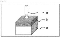
- Figure 1 shows a schematic diagram illustrating an embodiment of use of the material for built up edge formation of the present embodiment.
- the material for built up edge formation of the present embodiment comprises a resin block b and further comprises, if necessary, a difficult-to-cut block c having a Vickers hardness of 300° or more below the resin block b.
- the material for built up edge formation is subjected to cutting work using a cutting tool a from the resin block b side so that a built up edge is formed at the cutting edge of the cutting tool a exposed to a high temperature and a high pressure during the cutting work.
- the "built up edge” is some scrapings fixed to the cutting edge of a cutting tool due to a high pressure and temperature during cutting work and refers to a thin film-like or layer-like edge having a shape similar to that of the cutting edge.
- the cutting edge is rounded by the formation of the built up edge, there arise problems of decreased cutting ability, peeling off of a cutting surface, formation of narrow cracks, and a lack of gloss.
- a significant feature of the built up edge formed using the material for built up edge formation of the present embodiment is that the built up edge can reduce the abrasion of the cutting edge of a cutting tool in the cutting work of a workpiece material (particularly, a difficult-to-cut material) and can prolong the lifespan of the cutting tool. As a result, cost required for cutting tools, the number of runs of a cutting tool change step, or the like can be reduced. Thus, cutting work excellent in productivity is also achieved.
- the "cutting work” is not particularly limited as long as the cutting work is a process to cut a workpiece material. Examples thereof include drilling work, grooving work, turning work, and parting work. Among them, the material for built up edge formation of the present embodiment is suitable for drilling work using a drill.
- the resin block contains a high molecular weight compound (A) having a weight average molecular weight of 5 ⁇ 10 4 or higher and 1 ⁇ 10 6 or lower, a medium molecular weight compound (B) having a weight average molecular weight of 1 ⁇ 10 3 or higher and lower than 5 ⁇ 10 4 , and a carbon (C).
- A high molecular weight compound having a weight average molecular weight of 5 ⁇ 10 4 or higher and 1 ⁇ 10 6 or lower
- B medium molecular weight compound having a weight average molecular weight of 1 ⁇ 10 3 or higher and lower than 5 ⁇ 10 4
- C a carbon
- the high molecular weight compound (A) can function as a lubricant agent and is capable of improving the lubricity of the material for built up edge formation and forming a built up edge without the abrasion of the cutting edge.
- the high molecular weight compound (A) can further function as a molding agent and improves the moldability of the material for built up edge formation.
- the high molecular weight compound (A) is not particularly limited as long as its weight average molecular weight is 5 ⁇ 10 4 or higher and 1 ⁇ 10 6 or lower.
- Examples thereof include water soluble thermoplastic resins, non-water soluble thermoplastic resins, water soluble thermosetting resins, and non-water soluble thermosetting resins. Among them, a water soluble thermoplastic resin and/or a non-water soluble thermoplastic resin is preferred, and a water soluble thermoplastic resin is more preferred.
- the water soluble thermoplastic resin and the non-water soluble thermoplastic resin include, but are not particularly limited to, water soluble resins and non-water soluble resins described below.
- the "water soluble resin” refers to a high molecular compound that is dissolved in an amount of 1 g or larger with respect to 100 g of water at 25°C at 1 atm.
- One high molecular weight compound (A) may be used alone, or two or more thereof may be used in combination.
- Use of the water soluble resin tends to more effectively form a built up edge by the lubricity of the water soluble resin. Also, use of the water soluble resin moderately softens the surface hardness of the material for built up edge formation and therefore tends to be able to further reduce load to the cutting tool during built up edge formation.
- water soluble thermoplastic resin examples include, but are not particularly limited to: polyalkylene oxide compounds such as polyethylene oxide, polypropylene oxide, and polyethylene oxide-propylene oxide copolymers; polyalkylene glycol compounds such as polyethylene glycol and polypropylene glycol; ester compounds of polyalkylene glycol; ether compounds of polyalkylene glycol; monostearate compounds of polyalkylene glycol, such as polyethylene glycol monostearate, polypropylene glycol monostearate, and polyglycerin monostearate; water soluble urethanes; water soluble polyether resins; water soluble polyesters; sodium poly(meth)acrylate; polyacrylamide; polyvinylpyrrolidone; polyvinyl alcohol; saccharides such as cellulose and derivatives thereof; and modified polyamide.
- polyethylene oxide, polyethylene glycol, and a water soluble polyether resin are preferred from the viewpoint described above.
- non-water soluble resin tends to increase the surface hardness of the material for built up edge formation, as compared with use of the water soluble resin. This tends to improve the biting performance of the cutting edge of the cutting tool, for example, at the time of a built up edge formation step, further improve the rigidity of the material for built up edge formation, and improve handleability.
- non-water soluble thermoplastic resin examples include, but are not particularly limited to: urethane polymers; acrylic polymers; vinyl acetate polymers; vinyl chloride polymers; polyester polymers; polystyrene resins exemplified by polyethylene wax, styrene homopolymers (GPPS), styrene-butadiene copolymers (HIPS), and styrene-(meth)acrylic acid copolymers (e.g., MS resin); and copolymers thereof.
- urethane polymers acrylic polymers; vinyl acetate polymers; vinyl chloride polymers; polyester polymers; polystyrene resins exemplified by polyethylene wax, styrene homopolymers (GPPS), styrene-butadiene copolymers (HIPS), and styrene-(meth)acrylic acid copolymers (e.g., MS resin); and copolymers thereof.
- GPPS s
- the weight average molecular weight of the high molecular weight compound (A) is 5 ⁇ 10 4 or higher, preferably 6 ⁇ 10 4 or higher, more preferably 1 ⁇ 10 5 or higher, further preferably 1.25 ⁇ 10 5 or higher. Also, the weight average molecular weight of the high molecular weight compound (A) is 1 ⁇ 10 6 or lower, preferably 8 ⁇ 10 5 or lower, more preferably 7 ⁇ 10 5 or lower, further preferably 6 ⁇ 10 5 or lower. When the weight average molecular weight of the high molecular weight compound (A) is 5 ⁇ 10 4 or higher, the moldability tends to be improved.
- the weight average molecular weight of the high molecular weight compound (A) is 1 ⁇ 10 6 or lower, the lubricity is further improved.
- the respective weight average molecular weights of these compounds should satisfy the weight average molecular weight described above.
- the weight average molecular weight can be measured by a method described in Examples (the same holds true for the description below).
- the high molecular weight compound (A) may comprise a high molecular weight compound (A-1) having a weight average molecular weight of 3 ⁇ 10 5 or higher and 1 ⁇ 10 6 or lower and/or a high molecular weight compound (A-2) having a weight average molecular weight of 5 ⁇ 10 4 or higher and lower than 3 ⁇ 10 5 , and preferably comprises both of the high molecular weight compound (A-1) and the high molecular weight compound (A-2).
- Combined use of the high molecular weight compound (A-1) and the high molecular weight compound (A-2) tends to further improve the moldability and the lubricity and be able to more effectively form a built up edge without the abrasion of the cutting edge.
- the weight average molecular weight of the high molecular weight compound (A-1) is 3 ⁇ 10 5 or higher, preferably 4 ⁇ 10 5 or higher, more preferably 4.5 ⁇ 10 5 or higher, further preferably 5 ⁇ 10 5 or higher. Also, the weight average molecular weight of the high molecular weight compound (A-1) is 1 ⁇ 10 6 or lower, preferably 8 ⁇ 10 5 or lower, more preferably 7 ⁇ 10 5 or lower, further preferably 6 ⁇ 10 5 or lower.
- the content of the high molecular weight compound (A-1) in the material for built up edge formation is preferably 5 parts by mass or larger, more preferably 10 parts by mass or larger, further preferably 15 parts by mass or larger, with respect to 100 parts by mass in total of the high molecular weight compound (A), the medium molecular weight compound (B), and the carbon (C).
- the content of the high molecular weight compound (A-1) in the resin block is preferably 35 parts by mass or smaller, more preferably 30 parts by mass or smaller, further preferably 25 parts by mass or smaller, with respect to 100 parts by mass in total of the high molecular weight compound (A), the medium molecular weight compound (B), and the carbon (C).
- the content of the high molecular weight compound (A-1) is 5 parts by mass or larger, the moldability tends to be further improved.
- the content of the high molecular weight compound (A-1) is 35 parts by mass or smaller, there is a tendency to further improve the lubricity and be able to more effectively form a built up edge without the abrasion of the cutting edge.
- the weight average molecular weight of the high molecular weight compound (A-2) is 5 ⁇ 10 4 or higher, preferably 6 ⁇ 10 4 or higher, more preferably 1 ⁇ 10 5 or higher, further preferably 1.25 ⁇ 10 5 or higher. Also, the weight average molecular weight of the high molecular weight compound (A-2) is lower than 3 ⁇ 10 5 , preferably 2.5 ⁇ 10 5 or lower, more preferably 2 ⁇ 10 5 or lower.
- the content of the high molecular weight compound (A-2) in the resin block is preferably 5 parts by mass or larger, more preferably 10 parts by mass or larger, further preferably 15 parts by mass or larger, with respect to 100 parts by mass in total of the high molecular weight compound (A), the medium molecular weight compound (B), and the carbon (C). Also, the content of the high molecular weight compound (A-2) in the resin block is preferably 35 parts by mass or smaller, more preferably 30 parts by mass or smaller, further preferably 25 parts by mass or smaller, with respect to 100 parts by mass in total of the high molecular weight compound (A), the medium molecular weight compound (B), and the carbon (C).
- the content of the high molecular weight compound (A-2) is 5 parts by mass or larger, there is a tendency to further improve the lubricity and be able to more effectively form a built up edge without the abrasion of the cutting edge.
- the content of the high molecular weight compound (A-2) is 35 parts by mass or smaller, the moldability tends to be further improved.
- the content of the high molecular weight compound (A) in the resin block is preferably 10 parts by mass or larger, more preferably 20 parts by mass or larger, further preferably 25 parts by mass or larger, still further preferably 30 parts by mass or larger, with respect to 100 parts by mass in total of the high molecular weight compound (A), the medium molecular weight compound (B), and the carbon (C). Also, the content of the high molecular weight compound (A) in the resin block is preferably 60 parts by mass or smaller, more preferably 55 parts by mass or smaller, further preferably 50 parts by mass or smaller, with respect to 100 parts by mass in total of the high molecular weight compound (A), the medium molecular weight compound (B), and the carbon (C).
- the content of the high molecular weight compound (A) is 10 parts by mass or larger, there is a tendency to further improve the lubricity and be able to more effectively form a built up edge without the abrasion of the cutting edge.
- the content of the high molecular weight compound (A) is 10 parts by mass or larger, there is a tendency to improve the following properties and the tenacity and improve the cutting workability of a curved surface.
- the content of the high molecular weight compound (A) is 65 parts by mass or smaller, the moldability tends to be further improved.
- the medium molecular weight compound (B) can function as a lubricant agent and is capable of improving the lubricity of the material for built up edge formation and forming a built up edge without the abrasion of the cutting edge.
- the medium molecular weight compound (B) is not particularly limited as long as its weight average molecular weight is 1 ⁇ 10 3 or higher and lower than 5 ⁇ 10 4 .
- Examples thereof include water soluble thermoplastic resins, non-water soluble thermoplastic resins, water soluble thermosetting resins, and non-water soluble thermosetting resins. Among them, a water soluble thermoplastic resin or a non-water soluble thermoplastic resin is preferred, and a water soluble thermoplastic resin is more preferred.
- resins that are resins of the same types as in the water soluble resin and the non-water soluble resin described above and have a weight average molecular weight of 1 ⁇ 10 3 or higher and lower than 5 ⁇ 10 4 can be used as the water soluble thermoplastic resin and the non-water soluble thermoplastic resin.
- One medium molecular weight compound (B) may be used alone, or two or more thereof may be used in combination.
- Examples of the medium molecular weight compound (B) include, but are not particularly limited to: polyalkylene glycol compounds such as polyethylene glycol, polypropylene glycol, and polytetramethylene glycol; monoether compounds of polyalkylene oxide, such as polyethylene oxide oleyl ether, polyethylene oxide cetyl ether, polyethylene oxide stearyl ether, polyethylene oxide lauryl ether, polyethylene oxide nonyl phenyl ether, and polyethylene oxide octyl phenyl ether; monostearate compounds of polyalkylene oxide, such as polyethylene oxide monostearate, polyethylene oxide sorbitan monostearate, and polyglycerin monostearate; and polyalkylene oxide compounds such as polyethylene oxide, polypropylene oxide, and polyethylene oxide-propylene oxide copolymers. Among them, polyethylene oxide monostearate is preferred. Use of such a medium molecular weight compound (B) tends to further improve the lubricity and be able to more
- the weight average molecular weight of the medium molecular weight compound (B) is 1 ⁇ 10 3 or higher, preferably 1.25 ⁇ 10 3 or higher, more preferably 1.5 ⁇ 10 3 or higher, further preferably 2 ⁇ 10 3 or higher, still further preferably 2.5 ⁇ 10 3 or higher, particularly preferably 3 ⁇ 10 3 or higher. Also, the weight average molecular weight of the medium molecular weight compound (B) is lower than 5 ⁇ 10 4 , preferably 2.5 ⁇ 10 4 or lower, more preferably 2 ⁇ 10 4 or lower, further preferably 1 ⁇ 10 4 or lower, still further preferably 7.5 ⁇ 10 3 or lower, particularly preferably 5 ⁇ 10 3 or lower.
- the moldability is further improved.
- the weight average molecular weight of the medium molecular weight compound (B) is lower than 5 ⁇ 10 4 , there is a tendency to further improve the lubricity and be able to more effectively form a built up edge without the abrasion of the cutting edge.
- the content of the medium molecular weight compound (B) in the resin block is preferably 10 parts by mass or larger, more preferably 20 parts by mass or larger, further preferably 30 parts by mass or larger, with respect to 100 parts by mass in total of the high molecular weight compound (A), the medium molecular weight compound (B), and the carbon (C). Also, the content of the medium molecular weight compound (B) in the resin block is preferably 75 parts by mass or smaller, more preferably 60 parts by mass or smaller, further preferably 45 parts by mass or smaller, still further preferably 40 parts by mass or smaller, with respect to 100 parts by mass in total of the high molecular weight compound (A), the medium molecular weight compound (B), and the carbon (C).
- the content of the medium molecular weight compound (B) is 10 parts by mass or larger, there is a tendency to further improve the lubricity and be able to more effectively form a built up edge without the abrasion of the cutting edge.
- the content of the medium molecular weight compound (B) is 75 parts by mass or smaller, the moldability tends to be further improved.
- a high molecular weight compound (A) and a medium molecular weight compound (B) although use of the high molecular weight compound (A) alone, for example, reduces the moldability or lubricity of the material for built up edge formation due to too high a viscosity or too high a melting point of the material for built up edge formation, this can be suppressed.
- medium molecular weight compound (B) alone reduces the moldability or lubricity of the material for built up edge formation due to too low a viscosity or too low a melting point of the material for built up edge formation, this can be suppressed.
- the high molecular weight compound (A) which is a thermoplastic resin having a weight average molecular weight of 5 ⁇ 10 4 or higher and 1 ⁇ 10 6 or lower
- the medium molecular weight compound (B) which is a thermoplastic resin having a weight average molecular weight of 1 ⁇ 10 3 or higher and 2 ⁇ 10 4 or lower is preferred.
- the carbon (C) can function as a solid lubricant agent and is a component that improves the lubricity of the material for built up edge formation and forms a built up edge.
- the carbon (C) is not particularly limited. Examples thereof include natural graphite, artificial graphite, active carbon, acetylene black, carbon black, colloidal graphite, pyrolytic graphite, expanded graphite, and flake graphite. Among others, a carbon (C) whose shape is a flake shape is preferred. The carbon (C) whose shape is a flake shape tends to further improve the abrasion reducing performance.
- One carbon (C) may be used alone, or two or more thereof may be used in combination.
- the average particle size of the carbon (C) is preferably 100 ⁇ m or larger, more preferably 125 ⁇ m or larger, further preferably 150 ⁇ m or larger, still further preferably 175 ⁇ m or larger, still further preferably 200 ⁇ m or larger, particularly preferably 225 ⁇ m or larger. Also, the average particle size of the carbon (C) is preferably 1000 ⁇ m or smaller, more preferably 750 ⁇ m or smaller, further preferably 500 ⁇ m or smaller, particularly preferably 300 ⁇ m or smaller. When the average particle size of the carbon (C) is 100 ⁇ m or larger, the lubricity and the moldability are further improved.
- the average particle size of the carbon (C) is 1000 ⁇ m or smaller, there is a tendency to further reduce the abrasion of the cutting tool.
- the respective average particle sizes of the carbons (C) should satisfy the range described above.
- the average particle size of the carbon (C) refers to a median size.
- the median size means a particle diameter that is obtained from the cumulative distribution curve (number based) of particle sizes and becomes 50% height in the curve (D50 value), and can be measured by a method described in Examples.
- the content of the carbon (C) in the resin block is preferably 5 parts by mass or larger, more preferably 15 parts by mass or larger, further preferably 20 parts by mass or larger, still further preferably 25 parts by mass or larger, particularly preferably 30 parts by mass or larger, with respect to 100 parts by mass in total of the high molecular weight compound (A), the medium molecular weight compound (B), and the carbon (C).
- the content of the carbon (C) in the resin block is preferably 70 parts by mass or smaller, more preferably 65 parts by mass or smaller, further preferably 60 parts by mass or smaller, with respect to 100 parts by mass in total of the high molecular weight compound (A), the medium molecular weight compound (B), and the carbon (C).
- the content of the carbon (C) is 5 parts by mass or larger, the lubricity tends to be further improved.
- the content of the carbon (C) is 70 parts by mass or smaller, the moldability tends to be further improved.
- the material for built up edge formation of the present embodiment may optionally contain an additional component.
- additional component include lubricity improving components, plasticizers, softening agents, surface conditioners, leveling agents, antistatic agents, emulsifiers, antifoaming agents, wax additives, coupling agents, rheology controlling agents, antiseptics, antifungal agents, antioxidants, light stabilizers, nucleating agents, organic fillers, inorganic fillers, solid lubricant agents, heat stabilizers, and colorants.
- lubricity improving components include, but are not particularly limited to: amide compounds exemplified by ethylenebisstearamide, oleic acid amide, stearic acid amide, and methylenebisstearamide; fatty acid compounds exemplified by lauric acid, stearic acid, palmitic acid, and oleic acid; fatty acid ester compounds typified by butyl stearate, butyl oleate, and glycol laurate; aliphatic hydrocarbon compounds typified by liquid paraffin; and higher aliphatic alcohols typified by oleyl alcohol. At least one of these lubricity improving components can be selected.
- solid lubricant agents other than the carbon (C) include, but are not particularly limited to, molybdenum disulfide, tungsten disulfide, molybdenum compounds, polytetrafluoroethylene, and polyimide.
- the thickness of the resin block is preferably 0.05 cm or larger, more preferably 0.1 cm or larger, further preferably 0.2 cm or larger.
- the upper limit of the thickness of the resin block is not particularly limited and is preferably, for example, 5 cm or smaller.
- the difficult-to-cut block is not particularly limited as long as the block has a Vickers hardness of 300° or more. Examples thereof include a fiber reinforced composite material and/or a difficult-to-cut metal material.
- the difficult-to-cut block is positioned below the resin block and functions as a site that receives the cutting edge of the cutting tool that has penetrated the resin block. The cutting edge of the cutting tool that has come into the difficult-to-cut block is exposed to a higher temperature and a higher pressure. Thus, the built up edge can be formed, without the abrasion of the cutting edge, from the components supplied from the resin block.
- the "Vickers hardness" can be measured using a Vickers hardness meter.
- the fiber reinforced composite material is not particularly limited as long as the composite material is made of a matrix resin and a reinforcing fiber.
- the matrix resin include, but are not particularly limited to: thermosetting resins such as epoxy resins, phenol resins, cyanate resins, vinyl ester resins, and unsaturated polyester resins; and thermoplastic resins such as ABS (acrylonitrile-butadiene-styrene) resins, PA (polyamide) resins, PP (polypropylene) resins, PC (polycarbonate) resins, methyl methacrylate resins, polyethylene, and acryl, and polyester resins.
- the reinforcing fiber include, but are not particularly limited to, glass fiber, carbon fiber, and aramid fiber.
- Examples of the form of the reinforcing fiber include, but are not particularly limited to, filaments, tows, cloths, blades, chops, milled fibers, felt mats, papers, and prepregs.
- Specific examples of such a fiber reinforced composite material include, but are not particularly limited to, fiber reinforced plastics (FRP) such as carbon fiber reinforced plastics (CFRP), glass fiber reinforced plastics (GFRP), and aramid fiber reinforced plastics (AFRP).
- FRP fiber reinforced plastics
- CFRP carbon fiber reinforced plastic
- GFRP glass fiber reinforced plastics
- AFRP aramid fiber reinforced plastics
- CFRP carbon fiber reinforced plastic
- the fiber reinforced composite material may optionally contain an additional component such as an inorganic filler or an organic filler.
- the fiber reinforced plastics conceptually comprise a reinforcing fiber and a thermosetting resin and/or a thermoplastic resin.
- fiber reinforced composite materials comprising a reinforcing fiber and a thermoplastic resin are also referred to as FRTP (fiber reinforced thermoplastics).
- FRTP fiber reinforced thermoplastics
- CFRTP carbon fiber reinforced thermoplastics
- the difficult-to-cut metal material is not particularly limited as long as the difficult-to-cut metal material is a metal generally used as a structural material. Examples thereof include titanium alloy, aluminum alloy, magnesium alloy, low alloy steel, stainless steel, and heat resistant alloy. Among them, titanium alloy is preferred.
- the titanium alloy is particularly preferably Ti-6Al-4V which is composed of titanium, aluminum, and vanadium and has higher hardness.
- One difficult-to-cut metal material may be used alone, or two or more thereof may be used as a multilayer body.
- the thickness of the difficult-to-cut block is preferably 0.3 cm or larger, more preferably 0.5 cm or larger, further preferably 1 cm or larger.
- the upper limit of the thickness of the difficult-to-cut block is not particularly limited and is preferably, for example, 3 cm or smaller.
- the material for built up edge formation of the present embodiment may have an adhesive layer below the difficult-to-cut block in order to fix the material for built up edge formation so as to be immovable during a built up edge formation step.
- the component constituting the adhesive layer is not particularly limited and is, for example, a thermoplastic resin and/or a thermosetting resin.
- the thermoplastic resin include, but are not particularly limited to, urethane polymers, acrylic polymers, vinyl acetate polymers, vinyl chloride polymers, polyester polymers, and copolymers thereof.
- the thermosetting resin include, but are not particularly limited to, resins such as phenol resins, epoxy resins, melamine resins, urea resins, unsaturated polyester resins, alkyd resins, polyurethane, thermosetting polyimide, and cyanate resins.
- an acrylic polymer is preferred because of being capable of easily adhering at ordinary temperature.
- a solvent type acrylic pressure sensitive adhesive and an acrylic emulsion type pressure sensitive adhesive (aqueous) are more preferred.
- the adhesive layer may optionally contain a degradation preventing agent such as an antioxidant, and an inorganic filler such as calcium carbonate, talc, or silica, as components of the adhesive layer.
- a degradation preventing agent such as an antioxidant
- an inorganic filler such as calcium carbonate, talc, or silica
- the thickness of the adhesive layer is not particularly limited and is preferably 0.01 mm or larger, more preferably 0.05 mm or larger. Also, the thickness of the adhesive layer is preferably 5 mm or smaller, more preferably 2.5 mm or smaller.
- the method for producing the material for built up edge formation of the present embodiment is not particularly limited, and a conventional method known in the art for molding a resin composition comprising a resin such as a polymer material, and a filler (e.g., an inorganic filler) into the form of a block can be widely used.
- a resin composition comprising a resin such as a polymer material, and a filler (e.g., an inorganic filler) into the form of a block can be widely used.
- Examples of such a production method include: a method which involves mixing the high molecular weight compound (A), the medium molecular weight compound (B), and the carbon (C) in the presence or absence of a solvent, applying the mixture to a support, solidifying the mixture by cooling to form a block, and then peeling off the support therefrom to obtain the material for built up edge formation; and a method which involves mixing the high molecular weight compound (A), the medium molecular weight compound (B), and the carbon (C) in the presence or absence of a solvent, extrusion molding the mixture into a block shape, and cutting the block, if necessary, to obtain the material for built up edge formation.
- examples of the method for producing the multilayer body include, but are not particularly limited to, a method which involves pressure bonding the resin block to the difficult-to-cut block.
- the method for forming an adhesive layer on the surface of the difficult-to-cut block in the material for built up edge formation is not particularly limited as long as the method is known in the art and industrially used. Specific examples thereof include: a method which involves forming the adhesive layer by a roll method, a curtain coating method, a spraying method, or the like; and a method which involves forming in advance the adhesive layer having the desired thickness using a roll, a T-die extruder, or the like.
- the thickness of the adhesive layer is not particularly limited, and the optimum thickness can be appropriately selected according to the curvature of the workpiece material and the configuration of the material for built up edge formation.
- the built up edge formation method of the present embodiment has a built up edge formation step of forming a built up edge at the cutting edge of a cutting tool by cutting a material for built up edge formation with the cutting tool.
- the material for built up edge formation has a difficult-to-cut block, it is preferred that the cutting edge of the cutting tool should come into the member from the resin block side.
- the number of rotations of the tool to come into the material for built up edge formation, the cutting rate, the material of the tool, the type of coating on the tool surface, and the shape of the tool are not particularly limited.
- one example of built up edge formation conditions will be described.
- the number of rotations of the cutting tool to come into the material for built up edge formation is not particularly limited and is preferably 100 rpm or more and 10,000 rpm or less, more preferably 200 rpm or more and 8,000 rpm or less. Also, the number of rotations of the cutting tool is preferably 200 rpm or more and 5,000 rpm or less. When the number of rotations of the cutting tool is 100 rpm or more, the built up edge formation tends to be promoted because the cutting edge of the cutting tool is exposed to an environment of a temperature and a pressure that facilitate forming the built up edge.
- the cutting rate at which the cutting tool comes into the material for built up edge formation is not particularly limited and is preferably 1 mm/min or more and 100 mm/min or less, more preferably 1 mm/min or more and 50 mm/min or less. Also, the cutting rate of the cutting tool is preferably 1 mm/min or more and 10 mm/min or less.
- the material of the cutting tool is not particularly limited. Specific examples thereof include steel, aluminum, stainless, high speed stainless comprising tungsten, and cemented carbides comprising tungsten carbide and cobalt.
- the presence or absence or type of coating for the surface treatment of the cutting tool is not particularly limited.
- Specific examples of the type of the coating include diamond coating, diamond like coating, titanium carbide, titanium nitride, and aluminum oxide.
- the type or shape of the cutting tool is not particularly limited. Specific examples thereof include drills, routers, end mills, face milling cutters, turning tools, boring bars, electrodeposition tools, and rim saws.
- the "cutting work” is not particularly limited as long as the cutting work is a process to cut a workpiece material. Examples thereof include drilling work, grooving work, turning work, and parting work. Among them, drilling work using a drill (hereinafter, also simply referred to as “drilling work”) is preferred.
- the retention time is preferably 1 second or longer, more preferably 15 seconds or longer, further preferably 30 seconds or longer.
- the upper limit of the retention time is not particularly limited and is preferably 10 minutes or shorter.
- the retention time refers to the time for which the cutting tool remains in the resin block.
- the retention time is the time for which the cutting tool remains in the resin block and the difficult-to-cut block.
- the cutting tool of the present embodiment has a built up edge obtained from the material for built up edge formation described above.
- a cutting tool can be obtained by forming the built up edge by the built up edge formation method described above and can be a cutting tool having the built up edge obtained by the built up edge formation method.
- the cutting work method of the present embodiment has a cutting step of cutting a workpiece material using the cutting tool described above.
- a general cutting work technique can be used. Examples thereof include cutting work that is performed while a site under cutting work and/or the cutting tool is cooled using a gas or a liquid.
- Examples of the method for cooling a site under cutting work and/or the cutting tool using a gas include: a method which involves supplying a compressed gas to the site under cutting work and/or the cutting tool; and a method which involves supplying an ambient gas to the cutting work site and/or the cutting tool by aspirating the gas in the neighborhood of the site under cutting work and/or the cutting tool.
- a tool and a method for cutting work are not particularly limited. Specific examples thereof include drilling work to form through-holes or non-through holes using a drill as well as a router, a milling cutter, an end mill, a side cutter, or the like, and processing to cut off a workpiece material with a router, a pipe cutter, an end mill, a metal saw, or the like. Also, a coating film of titanium, diamond, diamond like carbon, or the like may be formed on the cutting edge of the cutting tool in order to enhance its hardness and thereby suppress the abrasion.
- Examples of the workpiece material that is subject include, but are not particularly limited to, a fiber reinforced composite material, a difficult-to-cut metal material, and a composite material of the fiber reinforced composite material and the difficult-to-cut metal material.
- the fiber reinforced composite material is not particularly limited as long as the composite material is made of a matrix resin and a reinforcing fiber.
- the matrix resin include, but are not particularly limited to: thermosetting resins such as epoxy resins, phenol resins, cyanate resins, vinyl ester resins, and unsaturated polyester resins; and thermoplastic resins such as ABS (acrylonitrile-butadiene-styrene) resins, PA (polyamide) resins, PP (polypropylene) resins, PC (polycarbonate) resins, methyl methacrylate resins, polyethylene, and acryl, and polyester resins.
- the reinforcing fiber include, but are not particularly limited to, glass fiber, carbon fiber, and aramid fiber.
- Examples of the form of the reinforcing fiber include, but are not particularly limited to, filaments, tows, cloths, blades, chops, milled fibers, felt mats, papers, and prepregs.
- Specific examples of such a fiber reinforced composite material include, but are not particularly limited to, fiber reinforced plastics (FRP) such as carbon fiber reinforced plastics (CFRP), glass fiber reinforced plastics (GFRP), and aramid fiber reinforced plastics (AFRP).
- FRP fiber reinforced plastics
- CFRP carbon fiber reinforced plastic
- GFRP glass fiber reinforced plastics
- AFRP aramid fiber reinforced plastics
- CFRP carbon fiber reinforced plastic
- the fiber reinforced composite material may optionally contain an additional component such as an inorganic filler or an organic filler.
- the fiber reinforced plastics conceptually comprise a reinforcing fiber and a thermosetting resin and/or a thermoplastic resin.
- fiber reinforced composite materials comprising a reinforcing fiber and a thermoplastic resin are also referred to as FRTP (fiber reinforced thermoplastics).
- FRTP fiber reinforced thermoplastics
- CFRTP carbon fiber reinforced thermoplastics
- the difficult-to-cut metal material is not particularly limited as long as the difficult-to-cut metal material is a metal generally used as a structural material.
- examples thereof include titanium alloy, aluminum alloy, magnesium alloy, low alloy steel, stainless steel, and heat resistant alloy.
- titanium alloy is preferred.
- the titanium alloy is particularly preferably Ti-6Al-4V which is composed of titanium, aluminum, and vanadium and has higher hardness.
- the titanium alloy is a material that has tensile strength two times stronger than that of aluminum alloy and is also excellent in corrosion resistance and heat resistance. This difficult-to-cut material having high hardness requires special cutting work conditions or a cutting tool having a special shape for conventional techniques.
- use of the cutting tool of the present embodiment eliminates the need of special cutting work conditions or a cutting tool having a special shape and can further prolong the lifespan of the cutting tool.
- a metal material for use in, for example, materials for the bodywork structures of aircrafts is preferred.
- the effect of prolonging the lifespan of the cutting tool by use of the cutting tool of the present embodiment becomes more apparent for a metal having higher strength.
- One difficult-to-cut metal material may be used alone, or two or more thereof may be used as a multilayer body.
- the composite material of the fiber reinforced composite material and the difficult-to-cut metal material examples include, but are not particularly limited to, a material prepared as a composite from the fiber reinforced composite material and the difficult-to-cut metal material described above by lamination or the like.
- the fiber reinforced composite material and the difficult-to-cut metal material differ largely in optimum cutting conditions.
- Low speed feed at high speed rotation is suitable for the fiber reinforced composite material
- high speed feed at low speed rotation is suitable for the difficult-to-cut metal material. This is because, for example, for the drilling work of the difficult-to-cut metal material, a rise in the temperature of the drill is suppressed and the abrasion of the drill bit is suppressed.
- a heat labile diamond coated drill requires such drilling conditions.
- drilling conditions are changed between CFRP and titanium alloy, or drilling work is practiced under the same reasonable conditions, in actual processing sites.
- a cutting oil is injected during the drilling work of titanium alloy intended for aircrafts, or an approach of collecting dust with a dust collector while spraying cold air is performed, in order to prevent a rise in the temperature of the drill.
- use of the cutting tool of the present embodiment is secondarily effective for greatly relaxing restrictions on drilling conditions for the difficult-to-cut metal material which easily generates heat due to the heat of friction.
- Table 1 shows the specifications of each component used in the production of a material for built up edge formation, an adhesive layer, a base material, a router bit used in cutting work, and a cutting work instrument.
- Table 1 Category Notation in table Name Trade name/model Manufacturer Remarks Base material GFRP Glass fiber reinforced plastic plate G-10 Risho Kogyo Co., Ltd. Thickness: 20 mm CFRP Carbon fiber reinforced plastic plate - Ibaraki Kogyo K.K. Thickness: 20 mm Aluminum plate Material for aircraft, aluminum plate - - Thickness: 20 mm High molecular weight compound (A) A-1 Polyethylene oxide Alkox E-45 Meisei Chemical Works, Ltd.
- the carbon was dispersed in a solution consisting of a hexametaphosphoric acid solution and a few drops of triton, and the respective maximum lengths of projected carbon particles were measured using a laser diffraction particle size distribution analyzer. Then, the cumulative distribution curve (number based) of particle sizes was calculated. A particle diameter that became 50% height in the cumulative distribution curve (number based) was used as the average particle size.
- the weight average molecular weights of the high molecular weight compound (A) and the medium molecular weight compound (B) were calculated as relative average molecular weights by dissolving or dispersing each of the high molecular weight compound (A) and the medium molecular weight compound (B) in a 0.05% salt solution, followed by measurement by liquid chromatography involving GPC (gel permeation chromatography) columns with polyethylene glycol as standards.
- Multilayer bodies a to e were produced as members for built up edge formation according to the resin composition of a resin block, the type of a base material used as a difficult-to-cut block, and the configuration as shown in Table 2. Hereinafter, the method for producing each multilayer body will be described.
- Ten sheets thus obtained were layered and pressed at 80°C for 30 seconds to obtain a block having a thickness of 10 mm.
- the strongly adhesive face of a double faced tape having a thickness of 0.12 mm (No. 5612, manufactured by Nitto Denko Corp.) was affixed to one side of the block.
- the resultant was further affixed via the adhesive face of the block to one side of GFRP having a thickness of 20 mm (G-10, manufactured by Risho Kogyo Co., Ltd.) to obtain multilayer body a in which the block containing the resin composition was laminated with the base material GFRP.
- the strongly adhesive face of a double faced tape having a thickness of 0.12 mm (No. 5612, manufactured by Nitto Denko Corp.) was affixed to one side of the sheet.
- the resultant was further affixed via the adhesive face of the sheet to one side of CFRP having a thickness of 20 mm (manufactured by Ibaraki Kogyo K.K.) to obtain multilayer body b in which the block containing the resin composition was laminated with the base material CFRP.
- the strongly adhesive face of a double faced tape having a thickness of 0.12 mm (No. 5612, manufactured by Nitto Denko Corp.) was affixed to one side of the sheet.
- the resultant was further affixed via the adhesive face of the sheet to one side of CFRP having a thickness of 20 mm (manufactured by Ibaraki Kogyo K.K.) to obtain multilayer body c in which the block containing the resin composition was laminated with the base material CFRP.
- Ten sheets thus obtained were layered and pressed at 80°C for 30 seconds to obtain a block having a thickness of 10 mm.
- the strongly adhesive face of a double faced tape having a thickness of 0.12 mm (No. 5612, manufactured by Nitto Denko Corp.) was affixed to one side of the block.
- the resultant was further affixed via the adhesive face of the sheet to one side of an aluminum plate having a thickness of 20 mm (material for aircrafts, aluminum plate) to obtain multilayer body e in which the block containing the resin composition was laminated with the base material aluminum plate.
- Examples 1 to 10 a built up edge was formed at the cutting edge of a tool under conditions shown in Table 3 using the produced multilayer bodies a to e.
- Examples 1 to 4 adopted, as shown in Figure 1 the processing method in which the tool entered the multilayer body from the point of the tool.
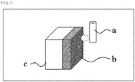
- Examples 5 to 10 adopted, as shown in Figure 2 the processing method in which the tool entered the multilayer body from the side of the tool. In either of the processing methods, the resin block of the multilayer body came in first contact with the tool. The cutting edge of the tool thus processed was observed to evaluate built up edge formation and chippings. The results are shown in Table 3.
- Comparative Examples 1 to 3 processing was performed in the same way as in Example 1 except that only a base material free from a resin block was used instead of the multilayer body. The cutting edge of the tool thus processed was observed to evaluate built up edge formation and chippings. The results are shown in Table 3.
- the cutting edge of the tool was observed under a microscope (V-LASER microscope VK-9700) to evaluate the state of occurrence of chippings.
- Figure 4 shows a photograph of the cutting edge of the cutting tool observed at a magnification of ⁇ 1500 under V-LASER microscope in Example 8.
- Example 8 a through groove formation process was performed using the tool with the formed built up edge produced in Example 8.
- a workpiece material was fixed to a machining center using a jig.
- the cutting work using the tool was performed under conditions involving use of CFRP having a thickness of 4 mm as the workpiece material and a processing distance of 5000 mm per tool to form a through groove having a width of 8 mm and a length of 5000 mm.
- Splintering of carbon fiber hereinafter, also referred to as "CF"
- CF carbon fiber
- a through groove formation process was performed in the same way as in Example 1 except that the tool used in Comparative Example 2 or a fresh tool was used.
- a workpiece material was fixed to a machining center using a jig.
- the cutting work using the tool was performed under conditions involving use of CFRP having a thickness of 4 mm as the workpiece material and a processing distance of 5000 mm per tool to form a through groove having a width of 8 mm and a length of 5000 mm.
- Splintering of carbon fiber hereinafter, also referred to as "CF"
- CF carbon fiber
- the material for built up edge formation of the present invention has industrial applicability as a sheet that improves the processing quality thereof and reduces processing cost.
Landscapes
- Engineering & Computer Science (AREA)
- Mechanical Engineering (AREA)
- Life Sciences & Earth Sciences (AREA)
- Forests & Forestry (AREA)
- Compositions Of Macromolecular Compounds (AREA)
- Cutting Tools, Boring Holders, And Turrets (AREA)
- Drilling Tools (AREA)
- Chemical & Material Sciences (AREA)
- Health & Medical Sciences (AREA)
- Chemical Kinetics & Catalysis (AREA)
- Medicinal Chemistry (AREA)
- Polymers & Plastics (AREA)
- Organic Chemistry (AREA)
Applications Claiming Priority (2)
| Application Number | Priority Date | Filing Date | Title |
|---|---|---|---|
| JP2016221942 | 2016-11-14 | ||
| PCT/JP2017/039226 WO2018088267A1 (ja) | 2016-11-14 | 2017-10-31 | 構成刃先形成用部材及び構成刃先形成方法 |
Publications (3)
| Publication Number | Publication Date |
|---|---|
| EP3539697A1 true EP3539697A1 (de) | 2019-09-18 |
| EP3539697A4 EP3539697A4 (de) | 2019-11-27 |
| EP3539697B1 EP3539697B1 (de) | 2024-12-18 |
Family
ID=62109550
Family Applications (1)
| Application Number | Title | Priority Date | Filing Date |
|---|---|---|---|
| EP17869893.2A Active EP3539697B1 (de) | 2016-11-14 | 2017-10-31 | Werkstoff zur formung einer aufgebauten kante und verfahren zur formung einer aufgebauten kante |
Country Status (5)
| Country | Link |
|---|---|
| US (1) | US11819930B2 (de) |
| EP (1) | EP3539697B1 (de) |
| JP (1) | JP7029113B2 (de) |
| TW (1) | TW201819072A (de) |
| WO (1) | WO2018088267A1 (de) |
Families Citing this family (1)
| Publication number | Priority date | Publication date | Assignee | Title |
|---|---|---|---|---|
| JP7227089B2 (ja) * | 2019-06-28 | 2023-02-21 | 株式会社ダイヤメット | 切削工具およびその表面保護皮膜の形成に使用する素材 |
Family Cites Families (94)
| Publication number | Priority date | Publication date | Assignee | Title |
|---|---|---|---|---|
| US2392481A (en) * | 1941-12-26 | 1946-01-08 | Detroit Broach Company | Machine tool cutter |
| US3220893A (en) | 1963-11-29 | 1965-11-30 | Union Carbide Corp | Metal quenching medium |
| JPS5819716B2 (ja) | 1972-03-02 | 1983-04-19 | キヤノン株式会社 | カコウホウホウ |
| JPS5053768A (de) | 1973-09-13 | 1975-05-13 | ||
| GB1438215A (en) | 1974-05-08 | 1976-06-03 | Lonz Ltd | High temperature lubricant |
| JPS5695991A (en) | 1979-12-29 | 1981-08-03 | Mitsubishi Metal Corp | Grinding with polyethylene glycol |
| JPS5927287B2 (ja) | 1980-12-24 | 1984-07-04 | 富士重工業株式会社 | ル−タ−ビツト |
| DE3170064D1 (en) | 1980-12-24 | 1985-05-23 | Fuji Heavy Ind Ltd | Router bit |
| GB2139538A (en) | 1983-05-07 | 1984-11-14 | Bl Tech Ltd | Structures fabricated from aluminium components |
| US4519732A (en) | 1983-12-09 | 1985-05-28 | United Technologies Corporation | Method for the machining of composite materials |
| DE3531786A1 (de) | 1985-09-06 | 1987-03-19 | Klenk R Hartmetallwerkzeug | Fraeser fuer das umfangs- oder nutenfraesen von hochleistungsverbundwerkstoffen |
| DE3833204A1 (de) | 1988-09-30 | 1990-04-05 | Hawera Praezisionswerkzeuge | Konturenfraeser |
| JP2855824B2 (ja) | 1990-08-08 | 1999-02-10 | 三菱瓦斯化学株式会社 | プリント配線板の孔明け加工法 |
| GB9102672D0 (en) * | 1991-02-07 | 1991-03-27 | Holders Technology Plc | Drilling printed circuit boards and dummy boards therefor |
| JP3169026B2 (ja) | 1991-12-18 | 2001-05-21 | 三菱瓦斯化学株式会社 | 小孔あけ用滑剤シート |
| EP0554822B1 (de) | 1992-02-06 | 1999-12-29 | Timcal Ag | Dornschmiermittel für die Herstellung nahtloser Rohre |
| SE507954C2 (sv) | 1992-09-15 | 1998-08-03 | Sandvik Ab | Metod att bearbeta kompositer |
| EP0571352B1 (de) | 1992-05-14 | 1997-10-01 | Sandvik Aktiebolag | Verfahren zum Bearbeiten von Verbundwerkstoffen |
| JP2590026Y2 (ja) * | 1993-07-26 | 1999-02-10 | 東芝タンガロイ株式会社 | 穴加工用工具のガイドパット |
| US5507603A (en) | 1993-08-05 | 1996-04-16 | Dai-Ichi Kogyo Seiyaku Co., Ltd. | Method for drilling thru-holes on a lamination substrate and a sheet used therein |
| JPH07112311A (ja) * | 1993-10-14 | 1995-05-02 | O S G Kk | 高硬度鋼用ドリル |
| JP2905142B2 (ja) * | 1996-05-08 | 1999-06-14 | 富士精工株式会社 | ドリル |
| JP3981168B2 (ja) | 1996-10-04 | 2007-09-26 | 共栄社化学株式会社 | 研削剤 |
| JPH1158882A (ja) * | 1997-08-20 | 1999-03-02 | Toppan Printing Co Ltd | 画像形成装置及び画像形成方法 |
| JP2000015624A (ja) | 1998-07-06 | 2000-01-18 | Murata Mfg Co Ltd | スライシング加工用粘着シート |
| JP4543243B2 (ja) | 1999-06-01 | 2010-09-15 | 昭和電工パッケージング株式会社 | 小径孔あけ加工用あて板および小径孔あけ加工方法 |
| JP2001098291A (ja) | 1999-09-27 | 2001-04-10 | Sanyo Special Steel Co Ltd | 金属の各種切削加工、特に乾式切削加工に優れた潤滑剤及び切削加工方法 |
| US6164876A (en) | 1999-10-30 | 2000-12-26 | Tungsten Industries, Inc | Cutting tool |
| JP4342119B2 (ja) | 2000-04-06 | 2009-10-14 | 株式会社神戸製鋼所 | 孔開け加工時の保護用あて板及びそれを使用したプリント配線基板の孔開け加工方法 |
| SG115399A1 (en) | 2000-09-04 | 2005-10-28 | Mitsubishi Gas Chemical Co | Lubricant sheet for making hole and method of making hole with drill |
| CN1275747C (zh) | 2000-09-14 | 2006-09-20 | 大智化学产业株式会社 | 用于钻小孔的导引板 |
| JP2002301632A (ja) | 2001-04-04 | 2002-10-15 | Fuji Seiki Kk | ワークパレット |
| US6773211B2 (en) | 2001-05-18 | 2004-08-10 | Novator Ab | Orbital drilling cutting tool |
| US6866450B2 (en) | 2001-10-31 | 2005-03-15 | Mitsubishi Gas Chemical Company, Inc. | Entry sheet for drilling and method for drilling hole |
| JP4010142B2 (ja) | 2001-12-13 | 2007-11-21 | 三菱瓦斯化学株式会社 | ドリル孔明け用エントリーシート |
| JP4106518B2 (ja) | 2001-10-31 | 2008-06-25 | 三菱瓦斯化学株式会社 | 孔明け用エントリーシート及びドリル孔明け加工法 |
| JP2003225814A (ja) | 2002-02-01 | 2003-08-12 | Nippon Shokubai Co Ltd | 基板孔あけ用潤滑剤および基板孔あけ用潤滑シート |
| JP2003301187A (ja) | 2002-02-05 | 2003-10-21 | Nippon Shokubai Co Ltd | 基板孔あけ用潤滑剤および基板孔あけ用潤滑シート |
| US6902360B2 (en) | 2002-02-08 | 2005-06-07 | General Electric Company | Method of cutting a hole in a composite material workpiece |
| US20050003169A1 (en) | 2003-01-28 | 2005-01-06 | Nobuyuki Ikeguchi | Lubricant sheet for drilling and method of drilling |
| JP4644414B2 (ja) | 2003-01-28 | 2011-03-02 | 三菱瓦斯化学株式会社 | 着色された孔あけ用滑剤シート |
| DE10308089A1 (de) | 2003-02-24 | 2004-09-02 | Airbus Deutschland Gmbh | Bohrvorrichtung |
| CN100365166C (zh) * | 2003-03-18 | 2008-01-30 | 浙江工业大学 | 一种刀具及其加工方法 |
| JP2005019657A (ja) | 2003-06-26 | 2005-01-20 | Nippon Synthetic Chem Ind Co Ltd:The | プリント配線基板穿孔用シート及びかかるシートを用いたプリント配線基板の穿孔方法 |
| US7090442B2 (en) | 2003-12-09 | 2006-08-15 | The Boeing Company | Shaper router and method |
| JP4639329B2 (ja) | 2004-12-01 | 2011-02-23 | 長崎県 | チタン合金の水中におけるエンドミル切削加工法 |
| JP4541133B2 (ja) | 2004-12-27 | 2010-09-08 | 昭和電工パッケージング株式会社 | 小口径孔あけ加工用エントリーボードと小口径孔あけ加工方法 |
| ITBO20050752A1 (it) | 2005-12-07 | 2007-06-08 | Jobs Spa | Portautensili per fresatrici, macchina fresatrice e procedimento di fresatura |
| KR100635108B1 (ko) | 2006-07-20 | 2006-10-18 | 주식회사 신진에스엠 | 원형톱날을 가진 금속 판재 절삭장치 |
| JP5863157B2 (ja) | 2006-12-18 | 2016-02-16 | 日東電工株式会社 | 粘着シート |
| US20080170917A1 (en) | 2007-01-17 | 2008-07-17 | David Hilker | Dual cutter router bit |
| JP2008229839A (ja) * | 2007-02-23 | 2008-10-02 | Kyocera Corp | 被覆層付き切削工具および切削装置 |
| JP5012100B2 (ja) | 2007-03-09 | 2012-08-29 | 三菱瓦斯化学株式会社 | ドリル孔明け用エントリーシート |
| DE102007017306A1 (de) | 2007-04-11 | 2008-10-16 | H.C. Starck Gmbh | Längliches Hartmetallwerkzeug mit Eisenbasis-Binder |
| US8398342B2 (en) | 2009-01-05 | 2013-03-19 | The Boeing Company | Workpiece vibration reduction |
| JP5385976B2 (ja) | 2009-04-27 | 2014-01-08 | 京セラ株式会社 | ドリル及びこのドリルを用いる被削材の切削方法 |
| US8827600B2 (en) | 2009-05-25 | 2014-09-09 | Hitachi Tool Engineering, Ltd. | Carbide end mill and cutting method using the end mill |
| JP5366003B2 (ja) | 2009-07-13 | 2013-12-11 | 日立ツール株式会社 | ルーターエンドミル |
| IL200742A (en) | 2009-09-03 | 2016-11-30 | Kennametal Inc | Swivel cutting tool with blade edge manufactured from venous pcd |
| DE102010004570B4 (de) | 2010-01-12 | 2011-09-22 | Tutech Innovation Gmbh | Verfahren zum Fräsen von langfaserverstärkten Verbundkunststoffen |
| CN102892538A (zh) | 2010-01-29 | 2013-01-23 | 柳下福藏 | 钻孔加工装置 |
| US20120315547A1 (en) | 2010-02-10 | 2012-12-13 | Mie University | Solid electrolyte composition, solid electrolyte, lithium ion secondary battery, and method for producing lithium ion secondary battery |
| JP5526924B2 (ja) | 2010-03-29 | 2014-06-18 | 三菱マテリアル株式会社 | エンドミル |
| GB201010061D0 (en) | 2010-06-16 | 2010-07-21 | Element Six Ltd | Rotary machine tools |
| US8602698B2 (en) | 2010-08-25 | 2013-12-10 | Kennametal Inc. | Combination end milling/drilling/reaming cutting tool |
| EP2633933B1 (de) | 2010-10-27 | 2018-10-03 | Subaru Corporation | Schneidevorrichtung mit abdeckung für das schneidewerkzeug |
| RU2526652C1 (ru) | 2010-12-28 | 2014-08-27 | Мицубиси Гэс Кемикал Компани, Инк. | Трафарет для высверливания отверстий |
| CN103097062B (zh) | 2011-01-31 | 2014-11-05 | 京瓷株式会社 | 钻头及使用该钻头的切削加工物的制造方法 |
| JP5960992B2 (ja) | 2011-02-04 | 2016-08-02 | 株式会社神戸製鋼所 | 樹脂被覆金属板 |
| US8858129B2 (en) | 2011-02-24 | 2014-10-14 | Kennametal Inc. | Segmented orbital drill |
| JP5851802B2 (ja) * | 2011-03-30 | 2016-02-03 | 富士重工業株式会社 | 炭素繊維強化樹脂複合材用ドリル |
| JP5729554B2 (ja) | 2011-03-31 | 2015-06-03 | 国立研究開発法人産業技術総合研究所 | 繊維強化型複合材料の加工方法及びその工具 |
| JP5445524B2 (ja) | 2011-06-27 | 2014-03-19 | 三菱瓦斯化学株式会社 | ドリル穴明け用エントリーシート |
| CN102504909B (zh) | 2011-11-04 | 2014-12-24 | 中科恒达石墨股份有限公司 | 一种用于石墨润滑剂的石墨材料 |
| JP5843102B2 (ja) * | 2012-01-19 | 2016-01-13 | 株式会社デンソー | 切削工具 |
| BR112014021235A2 (pt) | 2012-03-09 | 2021-02-17 | Mitsubishi Gas Chemical Company, Inc | folha de entrada para uso em perfuração |
| US9826643B2 (en) | 2012-03-21 | 2017-11-21 | Mitsubishi Gas Chemical Company, Inc. | Entry sheet for drilling and drilling method |
| RU2603401C2 (ru) | 2012-03-27 | 2016-11-27 | Мицубиси Гэс Кемикал Компани, Инк. | Прокладочный лист для сверления |
| TW201402804A (zh) | 2012-07-12 | 2014-01-16 | Scope Engineering & Trading Co Ltd | 鑽孔用潤滑蓋板及其製造方法 |
| DE102012221275A1 (de) | 2012-11-21 | 2014-05-22 | Hilti Aktiengesellschaft | Werkzeuggerät mit einer Sprühvorrichtung zur Staubbindung |
| CN104797389B (zh) * | 2012-12-28 | 2017-06-27 | 兼房株式会社 | 刃具 |
| US20140260884A1 (en) | 2013-03-14 | 2014-09-18 | Lien Ding Systems Co., Ltd. | Substrate processing method |
| MY180144A (en) | 2013-03-27 | 2020-11-23 | Mitsubishi Gas Chemical Co | Entry sheet for cutting fiber reinforced composite material or metal, and cutting method for cutting fiber reinforced material or metal |
| JP6293459B2 (ja) | 2013-11-15 | 2018-03-14 | 花王株式会社 | 毛髪化粧料 |
| JP6254458B2 (ja) | 2014-02-27 | 2017-12-27 | 株式会社北川鉄工所 | 繊維強化複合材の端面加工装置 |
| KR102365234B1 (ko) | 2014-03-31 | 2022-02-18 | 미츠비시 가스 가가쿠 가부시키가이샤 | 드릴 구멍 내기용 엔트리 시트 |
| EP3135716B1 (de) | 2014-04-24 | 2022-05-04 | Teijin Limited | Bearbeitetes kohlenstofffaserverstärktes harzprodukt mit endfläche und herstellungsverfahren dafür |
| JP6589506B2 (ja) | 2014-09-26 | 2019-10-16 | 三菱マテリアル株式会社 | ドリル及びドリルヘッド |
| US10364401B2 (en) | 2015-07-07 | 2019-07-30 | Nanotech Industrial Solutions, Inc. | Industrial lubricant including metal chalcogenide particles and phosphorus-based additive |
| JP6256865B2 (ja) | 2015-08-06 | 2018-01-10 | 三菱瓦斯化学株式会社 | 切削加工補助潤滑材及び切削加工方法 |
| CN108290229B (zh) | 2015-11-26 | 2022-06-28 | 三菱瓦斯化学株式会社 | 纤维增强复合材料的切削加工方法 |
| CN106001611B (zh) | 2016-06-21 | 2018-02-27 | 北京航空航天大学 | 一种精密高速断续超声振动切削方法 |
| CN106077724B (zh) * | 2016-07-01 | 2018-08-21 | 江苏大学 | 一种固体润滑的金属切削刀具及其加工方法 |
| JP7094495B2 (ja) | 2017-04-25 | 2022-07-04 | 三菱瓦斯化学株式会社 | 切削加工補助潤滑材、切削加工補助潤滑シート、及びそれらを用いた切削加工方法 |
-
2017
- 2017-10-31 EP EP17869893.2A patent/EP3539697B1/de active Active
- 2017-10-31 US US16/349,466 patent/US11819930B2/en active Active
- 2017-10-31 JP JP2018550150A patent/JP7029113B2/ja active Active
- 2017-10-31 WO PCT/JP2017/039226 patent/WO2018088267A1/ja not_active Ceased
- 2017-11-01 TW TW106137691A patent/TW201819072A/zh unknown
Also Published As
| Publication number | Publication date |
|---|---|
| US20200189009A1 (en) | 2020-06-18 |
| EP3539697B1 (de) | 2024-12-18 |
| US11819930B2 (en) | 2023-11-21 |
| TW201819072A (zh) | 2018-06-01 |
| EP3539697A4 (de) | 2019-11-27 |
| JP7029113B2 (ja) | 2022-03-03 |
| WO2018088267A1 (ja) | 2018-05-17 |
| JPWO2018088267A1 (ja) | 2019-09-26 |
Similar Documents
| Publication | Publication Date | Title |
|---|---|---|
| EP3333245B1 (de) | Schneidhilfsschmierstoff und schneidverfahren | |
| TWI607824B (zh) | 纖維強化複合材或金屬之切削加工用進入引導片及該切削加工方法、貫通孔、纖維強化複合材之製造方法及金屬之製造方法 | |
| EP3342517B1 (de) | Verfahren zum schneiden von faserverstärktem verbundstoffelement | |
| EP3633014B1 (de) | Schneidarbeitsunterstützendes schmiermaterial, schneidarbeitsunterstützende schmierblatt und schneidverfahren | |
| EP3539697B1 (de) | Werkstoff zur formung einer aufgebauten kante und verfahren zur formung einer aufgebauten kante | |
| EP3417968B1 (de) | Schneidverfahren und herstellungsverfahren für geschnittenes objekt | |
| EP3470154B1 (de) | Lochformungsverfahren | |
| US11097357B2 (en) | Drill bit and hole formation method |
Legal Events
| Date | Code | Title | Description |
|---|---|---|---|
| STAA | Information on the status of an ep patent application or granted ep patent |
Free format text: STATUS: THE INTERNATIONAL PUBLICATION HAS BEEN MADE |
|
| PUAI | Public reference made under article 153(3) epc to a published international application that has entered the european phase |
Free format text: ORIGINAL CODE: 0009012 |
|
| STAA | Information on the status of an ep patent application or granted ep patent |
Free format text: STATUS: REQUEST FOR EXAMINATION WAS MADE |
|
| 17P | Request for examination filed |
Effective date: 20190416 |
|
| AK | Designated contracting states |
Kind code of ref document: A1 Designated state(s): AL AT BE BG CH CY CZ DE DK EE ES FI FR GB GR HR HU IE IS IT LI LT LU LV MC MK MT NL NO PL PT RO RS SE SI SK SM TR |
|
| AX | Request for extension of the european patent |
Extension state: BA ME |
|
| A4 | Supplementary search report drawn up and despatched |
Effective date: 20191025 |
|
| RIC1 | Information provided on ipc code assigned before grant |
Ipc: B23B 51/00 20060101ALI20191021BHEP Ipc: B26F 1/16 20060101ALI20191021BHEP Ipc: B23B 27/14 20060101AFI20191021BHEP Ipc: B23B 27/00 20060101ALI20191021BHEP Ipc: B23B 35/00 20060101ALI20191021BHEP Ipc: B23C 3/00 20060101ALI20191021BHEP Ipc: B23P 15/28 20060101ALI20191021BHEP Ipc: B23C 5/16 20060101ALI20191021BHEP |
|
| DAV | Request for validation of the european patent (deleted) | ||
| DAX | Request for extension of the european patent (deleted) | ||
| STAA | Information on the status of an ep patent application or granted ep patent |
Free format text: STATUS: EXAMINATION IS IN PROGRESS |
|
| 17Q | First examination report despatched |
Effective date: 20220314 |
|
| REG | Reference to a national code |
Ref country code: DE Ref legal event code: R079 Ipc: B23B0035000000 Ref country code: DE Ref legal event code: R079 Ref document number: 602017086876 Country of ref document: DE Free format text: PREVIOUS MAIN CLASS: B23B0027140000 Ipc: B23B0035000000 |
|
| GRAP | Despatch of communication of intention to grant a patent |
Free format text: ORIGINAL CODE: EPIDOSNIGR1 |
|
| STAA | Information on the status of an ep patent application or granted ep patent |
Free format text: STATUS: GRANT OF PATENT IS INTENDED |
|
| RIC1 | Information provided on ipc code assigned before grant |
Ipc: B23P 15/28 20060101ALI20240422BHEP Ipc: B26F 1/16 20060101ALI20240422BHEP Ipc: B23C 3/00 20060101ALI20240422BHEP Ipc: B23B 35/00 20060101AFI20240422BHEP |
|
| INTG | Intention to grant announced |
Effective date: 20240510 |
|
| GRAJ | Information related to disapproval of communication of intention to grant by the applicant or resumption of examination proceedings by the epo deleted |
Free format text: ORIGINAL CODE: EPIDOSDIGR1 |
|
| STAA | Information on the status of an ep patent application or granted ep patent |
Free format text: STATUS: EXAMINATION IS IN PROGRESS |
|
| INTC | Intention to grant announced (deleted) | ||
| GRAP | Despatch of communication of intention to grant a patent |
Free format text: ORIGINAL CODE: EPIDOSNIGR1 |
|
| STAA | Information on the status of an ep patent application or granted ep patent |
Free format text: STATUS: GRANT OF PATENT IS INTENDED |
|
| INTG | Intention to grant announced |
Effective date: 20240829 |
|
| GRAS | Grant fee paid |
Free format text: ORIGINAL CODE: EPIDOSNIGR3 |
|
| GRAA | (expected) grant |
Free format text: ORIGINAL CODE: 0009210 |
|
| STAA | Information on the status of an ep patent application or granted ep patent |
Free format text: STATUS: THE PATENT HAS BEEN GRANTED |
|
| AK | Designated contracting states |
Kind code of ref document: B1 Designated state(s): AL AT BE BG CH CY CZ DE DK EE ES FI FR GB GR HR HU IE IS IT LI LT LU LV MC MK MT NL NO PL PT RO RS SE SI SK SM TR |
|
| REG | Reference to a national code |
Ref country code: GB Ref legal event code: FG4D |
|
| REG | Reference to a national code |
Ref country code: CH Ref legal event code: EP |
|
| REG | Reference to a national code |
Ref country code: DE Ref legal event code: R096 Ref document number: 602017086876 Country of ref document: DE |
|
| REG | Reference to a national code |
Ref country code: IE Ref legal event code: FG4D |
|
| REG | Reference to a national code |
Ref country code: LT Ref legal event code: MG9D |
|
| PG25 | Lapsed in a contracting state [announced via postgrant information from national office to epo] |
Ref country code: HR Free format text: LAPSE BECAUSE OF FAILURE TO SUBMIT A TRANSLATION OF THE DESCRIPTION OR TO PAY THE FEE WITHIN THE PRESCRIBED TIME-LIMIT Effective date: 20241218 |
|
| PG25 | Lapsed in a contracting state [announced via postgrant information from national office to epo] |
Ref country code: FI Free format text: LAPSE BECAUSE OF FAILURE TO SUBMIT A TRANSLATION OF THE DESCRIPTION OR TO PAY THE FEE WITHIN THE PRESCRIBED TIME-LIMIT Effective date: 20241218 |
|
| PG25 | Lapsed in a contracting state [announced via postgrant information from national office to epo] |
Ref country code: BG Free format text: LAPSE BECAUSE OF FAILURE TO SUBMIT A TRANSLATION OF THE DESCRIPTION OR TO PAY THE FEE WITHIN THE PRESCRIBED TIME-LIMIT Effective date: 20241218 |
|
| PG25 | Lapsed in a contracting state [announced via postgrant information from national office to epo] |
Ref country code: NO Free format text: LAPSE BECAUSE OF FAILURE TO SUBMIT A TRANSLATION OF THE DESCRIPTION OR TO PAY THE FEE WITHIN THE PRESCRIBED TIME-LIMIT Effective date: 20250318 |
|
| REG | Reference to a national code |
Ref country code: NL Ref legal event code: MP Effective date: 20241218 |
|
| PG25 | Lapsed in a contracting state [announced via postgrant information from national office to epo] |
Ref country code: LV Free format text: LAPSE BECAUSE OF FAILURE TO SUBMIT A TRANSLATION OF THE DESCRIPTION OR TO PAY THE FEE WITHIN THE PRESCRIBED TIME-LIMIT Effective date: 20241218 Ref country code: GR Free format text: LAPSE BECAUSE OF FAILURE TO SUBMIT A TRANSLATION OF THE DESCRIPTION OR TO PAY THE FEE WITHIN THE PRESCRIBED TIME-LIMIT Effective date: 20250319 |
|
| PG25 | Lapsed in a contracting state [announced via postgrant information from national office to epo] |
Ref country code: RS Free format text: LAPSE BECAUSE OF FAILURE TO SUBMIT A TRANSLATION OF THE DESCRIPTION OR TO PAY THE FEE WITHIN THE PRESCRIBED TIME-LIMIT Effective date: 20250318 |
|
| PG25 | Lapsed in a contracting state [announced via postgrant information from national office to epo] |
Ref country code: NL Free format text: LAPSE BECAUSE OF FAILURE TO SUBMIT A TRANSLATION OF THE DESCRIPTION OR TO PAY THE FEE WITHIN THE PRESCRIBED TIME-LIMIT Effective date: 20241218 |
|
| REG | Reference to a national code |
Ref country code: AT Ref legal event code: MK05 Ref document number: 1751866 Country of ref document: AT Kind code of ref document: T Effective date: 20241218 |
|
| PG25 | Lapsed in a contracting state [announced via postgrant information from national office to epo] |
Ref country code: SM Free format text: LAPSE BECAUSE OF FAILURE TO SUBMIT A TRANSLATION OF THE DESCRIPTION OR TO PAY THE FEE WITHIN THE PRESCRIBED TIME-LIMIT Effective date: 20241218 |
|
| PG25 | Lapsed in a contracting state [announced via postgrant information from national office to epo] |
Ref country code: PL Free format text: LAPSE BECAUSE OF FAILURE TO SUBMIT A TRANSLATION OF THE DESCRIPTION OR TO PAY THE FEE WITHIN THE PRESCRIBED TIME-LIMIT Effective date: 20241218 |
|
| PG25 | Lapsed in a contracting state [announced via postgrant information from national office to epo] |
Ref country code: ES Free format text: LAPSE BECAUSE OF FAILURE TO SUBMIT A TRANSLATION OF THE DESCRIPTION OR TO PAY THE FEE WITHIN THE PRESCRIBED TIME-LIMIT Effective date: 20241218 |
|
| PG25 | Lapsed in a contracting state [announced via postgrant information from national office to epo] |
Ref country code: IS Free format text: LAPSE BECAUSE OF FAILURE TO SUBMIT A TRANSLATION OF THE DESCRIPTION OR TO PAY THE FEE WITHIN THE PRESCRIBED TIME-LIMIT Effective date: 20250418 |
|
| PG25 | Lapsed in a contracting state [announced via postgrant information from national office to epo] |
Ref country code: PT Free format text: LAPSE BECAUSE OF FAILURE TO SUBMIT A TRANSLATION OF THE DESCRIPTION OR TO PAY THE FEE WITHIN THE PRESCRIBED TIME-LIMIT Effective date: 20250421 |
|
| PG25 | Lapsed in a contracting state [announced via postgrant information from national office to epo] |
Ref country code: EE Free format text: LAPSE BECAUSE OF FAILURE TO SUBMIT A TRANSLATION OF THE DESCRIPTION OR TO PAY THE FEE WITHIN THE PRESCRIBED TIME-LIMIT Effective date: 20241218 |
|
| PG25 | Lapsed in a contracting state [announced via postgrant information from national office to epo] |
Ref country code: RO Free format text: LAPSE BECAUSE OF FAILURE TO SUBMIT A TRANSLATION OF THE DESCRIPTION OR TO PAY THE FEE WITHIN THE PRESCRIBED TIME-LIMIT Effective date: 20241218 Ref country code: AT Free format text: LAPSE BECAUSE OF FAILURE TO SUBMIT A TRANSLATION OF THE DESCRIPTION OR TO PAY THE FEE WITHIN THE PRESCRIBED TIME-LIMIT Effective date: 20241218 |
|
| PG25 | Lapsed in a contracting state [announced via postgrant information from national office to epo] |
Ref country code: SK Free format text: LAPSE BECAUSE OF FAILURE TO SUBMIT A TRANSLATION OF THE DESCRIPTION OR TO PAY THE FEE WITHIN THE PRESCRIBED TIME-LIMIT Effective date: 20241218 |
|
| PG25 | Lapsed in a contracting state [announced via postgrant information from national office to epo] |
Ref country code: CZ Free format text: LAPSE BECAUSE OF FAILURE TO SUBMIT A TRANSLATION OF THE DESCRIPTION OR TO PAY THE FEE WITHIN THE PRESCRIBED TIME-LIMIT Effective date: 20241218 |
|
| PG25 | Lapsed in a contracting state [announced via postgrant information from national office to epo] |
Ref country code: IT Free format text: LAPSE BECAUSE OF FAILURE TO SUBMIT A TRANSLATION OF THE DESCRIPTION OR TO PAY THE FEE WITHIN THE PRESCRIBED TIME-LIMIT Effective date: 20241218 |
|
| PG25 | Lapsed in a contracting state [announced via postgrant information from national office to epo] |
Ref country code: SE Free format text: LAPSE BECAUSE OF FAILURE TO SUBMIT A TRANSLATION OF THE DESCRIPTION OR TO PAY THE FEE WITHIN THE PRESCRIBED TIME-LIMIT Effective date: 20241218 |
|
| REG | Reference to a national code |
Ref country code: DE Ref legal event code: R097 Ref document number: 602017086876 Country of ref document: DE |
|
| PG25 | Lapsed in a contracting state [announced via postgrant information from national office to epo] |
Ref country code: DK Free format text: LAPSE BECAUSE OF FAILURE TO SUBMIT A TRANSLATION OF THE DESCRIPTION OR TO PAY THE FEE WITHIN THE PRESCRIBED TIME-LIMIT Effective date: 20241218 |
|
| PGFP | Annual fee paid to national office [announced via postgrant information from national office to epo] |
Ref country code: GB Payment date: 20250911 Year of fee payment: 9 |
|
| PGFP | Annual fee paid to national office [announced via postgrant information from national office to epo] |
Ref country code: FR Payment date: 20250908 Year of fee payment: 9 |
|
| PLBE | No opposition filed within time limit |
Free format text: ORIGINAL CODE: 0009261 |
|
| STAA | Information on the status of an ep patent application or granted ep patent |
Free format text: STATUS: NO OPPOSITION FILED WITHIN TIME LIMIT |
|
| 26N | No opposition filed |
Effective date: 20250919 |
|
| PGFP | Annual fee paid to national office [announced via postgrant information from national office to epo] |
Ref country code: DE Payment date: 20250902 Year of fee payment: 9 |