EP3528966B1 - Station zum auftragen von flüssigen stoffen auf steinmaterialien - Google Patents
Station zum auftragen von flüssigen stoffen auf steinmaterialien Download PDFInfo
- Publication number
- EP3528966B1 EP3528966B1 EP17803989.7A EP17803989A EP3528966B1 EP 3528966 B1 EP3528966 B1 EP 3528966B1 EP 17803989 A EP17803989 A EP 17803989A EP 3528966 B1 EP3528966 B1 EP 3528966B1
- Authority
- EP
- European Patent Office
- Prior art keywords
- slab
- roller
- applicator
- station according
- actuator
- Prior art date
- Legal status (The legal status is an assumption and is not a legal conclusion. Google has not performed a legal analysis and makes no representation as to the accuracy of the status listed.)
- Active
Links
Images


Classifications
-
- B—PERFORMING OPERATIONS; TRANSPORTING
- B05—SPRAYING OR ATOMISING IN GENERAL; APPLYING FLUENT MATERIALS TO SURFACES, IN GENERAL
- B05C—APPARATUS FOR APPLYING FLUENT MATERIALS TO SURFACES, IN GENERAL
- B05C11/00—Component parts, details or accessories not specifically provided for in groups B05C1/00 - B05C9/00
- B05C11/02—Apparatus for spreading or distributing liquids or other fluent materials already applied to a surface ; Controlling means therefor; Control of the thickness of a coating by spreading or distributing liquids or other fluent materials already applied to the coated surface
- B05C11/023—Apparatus for spreading or distributing liquids or other fluent materials already applied to a surface
- B05C11/025—Apparatus for spreading or distributing liquids or other fluent materials already applied to a surface with an essentially cylindrical body, e.g. roll or rod
-
- B—PERFORMING OPERATIONS; TRANSPORTING
- B05—SPRAYING OR ATOMISING IN GENERAL; APPLYING FLUENT MATERIALS TO SURFACES, IN GENERAL
- B05C—APPARATUS FOR APPLYING FLUENT MATERIALS TO SURFACES, IN GENERAL
- B05C11/00—Component parts, details or accessories not specifically provided for in groups B05C1/00 - B05C9/00
- B05C11/02—Apparatus for spreading or distributing liquids or other fluent materials already applied to a surface ; Controlling means therefor; Control of the thickness of a coating by spreading or distributing liquids or other fluent materials already applied to the coated surface
- B05C11/04—Apparatus for spreading or distributing liquids or other fluent materials already applied to a surface ; Controlling means therefor; Control of the thickness of a coating by spreading or distributing liquids or other fluent materials already applied to the coated surface with blades
- B05C11/041—Apparatus for spreading or distributing liquids or other fluent materials already applied to a surface ; Controlling means therefor; Control of the thickness of a coating by spreading or distributing liquids or other fluent materials already applied to the coated surface with blades characterised by means for positioning, loading, or deforming the blades
-
- B—PERFORMING OPERATIONS; TRANSPORTING
- B05—SPRAYING OR ATOMISING IN GENERAL; APPLYING FLUENT MATERIALS TO SURFACES, IN GENERAL
- B05C—APPARATUS FOR APPLYING FLUENT MATERIALS TO SURFACES, IN GENERAL
- B05C11/00—Component parts, details or accessories not specifically provided for in groups B05C1/00 - B05C9/00
- B05C11/02—Apparatus for spreading or distributing liquids or other fluent materials already applied to a surface ; Controlling means therefor; Control of the thickness of a coating by spreading or distributing liquids or other fluent materials already applied to the coated surface
- B05C11/04—Apparatus for spreading or distributing liquids or other fluent materials already applied to a surface ; Controlling means therefor; Control of the thickness of a coating by spreading or distributing liquids or other fluent materials already applied to the coated surface with blades
- B05C11/044—Apparatus for spreading or distributing liquids or other fluent materials already applied to a surface ; Controlling means therefor; Control of the thickness of a coating by spreading or distributing liquids or other fluent materials already applied to the coated surface with blades characterised by means for holding the blades
-
- B—PERFORMING OPERATIONS; TRANSPORTING
- B05—SPRAYING OR ATOMISING IN GENERAL; APPLYING FLUENT MATERIALS TO SURFACES, IN GENERAL
- B05C—APPARATUS FOR APPLYING FLUENT MATERIALS TO SURFACES, IN GENERAL
- B05C5/00—Apparatus in which liquid or other fluent material is projected, poured or allowed to flow on to the surface of the work
- B05C5/02—Apparatus in which liquid or other fluent material is projected, poured or allowed to flow on to the surface of the work the liquid or other fluent material being discharged through an outlet orifice by pressure, e.g. from an outlet device in contact or almost in contact, with the work
- B05C5/0208—Apparatus in which liquid or other fluent material is projected, poured or allowed to flow on to the surface of the work the liquid or other fluent material being discharged through an outlet orifice by pressure, e.g. from an outlet device in contact or almost in contact, with the work for applying liquid or other fluent material to separate articles
- B05C5/0212—Apparatus in which liquid or other fluent material is projected, poured or allowed to flow on to the surface of the work the liquid or other fluent material being discharged through an outlet orifice by pressure, e.g. from an outlet device in contact or almost in contact, with the work for applying liquid or other fluent material to separate articles only at particular parts of the articles
- B05C5/0216—Apparatus in which liquid or other fluent material is projected, poured or allowed to flow on to the surface of the work the liquid or other fluent material being discharged through an outlet orifice by pressure, e.g. from an outlet device in contact or almost in contact, with the work for applying liquid or other fluent material to separate articles only at particular parts of the articles by relative movement of article and outlet according to a predetermined path
Definitions
- the present invention relates to the field of working blocks and slabs of stone materials such as marble, granite and the like; in particular, the object of the invention is a station for applying fluid substances, such as, although without limitation, resins, to slabs of stone material.
- the natural stone materials used in the construction field such as marbles, granites and the like, shall be mostly treated with epoxy resins, that can be single-component resins or two-component resins, so as to improve the chemical and mechanical features thereof or simply the appearance thereof.
- the resins enter the cracks in the slabs, thus reinforcing the slabs and giving them a homogeneous surface.
- reinforcing webs or sheets made of artificial fibers like glass are fixed to the slabs of stone material by means of resins, to improve the mechanical performances thereof.
- the resin finishing is performed through process lines that, in addition to the loading and unloading operations, provide for:
- a 2-axis automatic machine that, after having read the slab contour, sprays the resin on the slab surface by means of a pump-nozzle system.
- the reinforcing webs or sheets can be also applied automatically to the slab surface, and are then covered with the resin applied manually or through the same 2-axis machine.
- the invention aims at solving the problems typical of the known machines and processes for applying fluid substances to stone materials.
- an important object of the invention is to provide a station for applying fluid substances to stone materials that is suitable to reduce the need for operators when applying these substances, especially when applying reinforcing resins.
- a further object of the invention is to provide a station for applying fluid substances to stone materials that allows to increase the work accuracy.
- a further object of the invention is to provide a station for applying fluid substances to stone materials that is suitable to speed up the whole process.
- a further important object of the invention is to provide a station for applying fluid substances to stone materials that allows to decrease the amount of used resin.
- a further important object of the invention is to provide a station for applying fluid substances to stone materials that allows to decrease the resin noxious emissions.
- a further object of the invention is to provide a station for applying fluid substances to stone materials that is reliable and requires reduced maintenance with respect to the prior art stations.
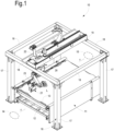
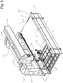
- number 10 indicates, as a whole, a station for applying fluid substances to a slab of stone material according to the invention. More in particular, the station is a resin finishing station for slabs of stone material.
- the resin finishing station 10 is inserted, for example, within a resin finishing line, not shown in the figures, comprised of various processing stations, such as a loading station, a slab drying station (comprising, for example, one or more drying ovens), a resin finishing station, a resin catalysis station, an optional second resin finishing station with a second catalysis station, and an unloading station.
- processing stations such as a loading station, a slab drying station (comprising, for example, one or more drying ovens), a resin finishing station, a resin catalysis station, an optional second resin finishing station with a second catalysis station, and an unloading station.
- a loading station such as a loading station, a slab drying station (comprising, for example, one or more drying ovens), a resin finishing station, a resin catalysis station, an optional second resin finishing station with a second catalysis station, and an unloading station.
- a resin finishing station such as a resin finishing line, not shown in the figures
- the resin finishing station 10 may be provided with means for applying a reinforcing web or sheet to the slab, that are not shown in the figures.
- the resin finishing station 10 comprises a base 11 integrating with a conveyor belt 12, the conveyor belt defining, at the top, a support surface 13 for the slab L of stone material, and a feed direction f from an entrance area 14 to an exit area 15 for interacting with respective processing stations of the resin finishing line.
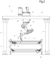
- the resin finishing station 10 also comprises a bearing structure 16, for example a gantry structure, provided with four pillars 17 arranged at the opposite ends, at opposite sides, of the conveyor belt and connected at the top by means of four crossbars 18. Between two crossbars 18, orthogonal to the slab feed direction f, the upper central crossbar 19 of the gantry structure is arranged, parallel to the direction f, preferably in correspondence of the centerline of the support surface 13. The upper central crossbar 19 is arranged spaced above the support surface 13, overlapping, i.e. intersecting, in plan, the area thereof.
- a numerically controlled automated moving device 20 is associated with the upper central crossbar 19 for moving a resin applicator 21 on the slab L.
- the moving device allows six degrees of freedom for the applicator 21, as it will be better explained below.
- the applicator 21 hangs from the upper central crossbar 19 through the moving device 20.
- the moving device 20 comprises a carriage 22 arranged slidable on the upper central crossbar 19, according to the direction g, i.e. parallel to the support surface of the slab L and parallel to the slab feed direction f.
- the crossbar 19 may be orthogonal to the crossbar of the example above, and the carriage therefore slides orthogonally to the direction f.
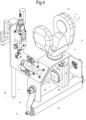
- an anthropomorphic arm 23 is provided, at the operative end 23A of which the resin applicator 21 is provided.
- the anthropomorphic arm 23 comprises a base 23B articulated to the carriage 22 according to a vertical axis z.
- a first intermediate member 23C A is articulated to the base 213B according to a horizontal axis h; to the first intermediate member 23C, a second intermediate member 23D is articulated according to a horizontal axis h'.
- the operative end 23A is hinged to the second intermediate member according to an axis k orthogonal to h or h'.
- the applicator 21 is articulated, through a support bracket 24, to the operative end 23A according to an axis orthogonal to the axis k thereof.
- the resin applicator 21 has a box-shaped central portion 25, to a part of which the support bracket 24 is fastened and with which, at opposite side with respect to the bracket 24, a resin distribution roller 26 is associated through a support to which it is hinged.
- the support of the roller comprises two support bodies 27, to the corresponding first ends of which the roller 26 is hinged, while the second ends thereof are integrally fixed to a shaft 28 passing inside the box-shaped central portion 25.
- the resin applicator 21 also comprises a pressing member allowing to press the roller 26 on the slab L.
- the pressing member is embodied by an actuator 29 suitable to generate a force on the support 27-28 so as to transmit this force to the roller 26 and to make the roller press on the slab L.
- the actuator 29 is a rotation actuator whose power output is defined by a rotating member 29A (rotating coaxially and integrally with the power axis n of the actuator), to which the shaft 28 is fixed (coaxially with the rotation axis n of the rotating member 29A), allowing to generate a torque J on the shaft 28 so that, when the roller 26 contacts the slab L and the support bodies 27 of the roller are arranged inclined (i.e.
- the direction of the torque J applied to the shaft in the direction of moving the roller towards the slab causes an increase in the pressure of the roller on the slab, while a decrease in the torque J in this direction generates a decrease of the pressure of the roller 26 on the slab L.
- An adjusting device is provided for regulating the pressure of the roller 26 on the slab L, suitable to act by regulating the force, i.e. the torque, of the actuator 29 acting on the support 27-28, i.e. on the set shaft-support bodies.
- the actuator 29 is a known rotation actuator of the pneumatic type and comprises, as well known, an adjusting device for regulating the actuation pressure for the compressed air (not shown in the figures) in the inner chambers of the actuator.
- the rotation actuator 29 has a given pressure value due to the compressed air in the inner chamber thereof, to which corresponds a torsion force, i.e. a torque, at the shaft 28 in the direction of keeping the roller into contact with the slab L.
- a torsion force i.e. a torque
- the slab transmits a strength preventing the roller from rotating around the axis of the shaft 28.
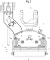
- a variant of the resin applicator 21 is shown, and in particular of the roller pressing member.
- two rotation actuators 129 are provided, fastened to the opposite flanks of the box-shaped central portion 25, and with the axes of the respective rotating members 129A matching the axes of the power output of the actuators, aligned together, i.e. they have a common rotation axis n.
- a support body 27 for the roller 26 is integrally fastened to each rotating member 129A, so that the roller is hinged to a pair of support bodies 27 rotating around a common axis n matching the power axes of the two rotation actuators 129.
- the operation is similar to that described above with reference to the single actuator with a shaft, to which the two roller support bodies are fixed.
- two adjusting devices are provided for regulating the pressure of the roller 26 on the slab L, suitable to act by regulating the force, i.e. the torque, of the actuators 29 on the supports 27.
- the resin applicator 21 also comprises a nozzle 30 from which the resin exits in order to be deposited on the slab, and which is associated with a resin supply system, not shown, comprising a pump for delivering the resin to the nozzle and one or more tanks for the resin, for example tanks for two components that are mixed before exiting from the nozzle to have a 2-component resin.
- a resin supply system not shown, comprising a pump for delivering the resin to the nozzle and one or more tanks for the resin, for example tanks for two components that are mixed before exiting from the nozzle to have a 2-component resin.
- Other types of resins are obviously possible.
- the compressed air system supplying the actuator, the resin supply system, and the electric system for powering the electric/electronic components of the actuator are not shown, as they are known to those skilled in the art.
- Walls and a ceiling (not shown) for insulating the station are provided around the gantry structure.
- Fig. 6 shows a variant of the station, indicated with number 100.
- the station comprises a base 11 integrating with a conveyor belt 12, the conveyor belt defining, at the top, a support surface 13 for the slab L of stone material, and a feed direction f from an entrance area to an exit area for interacting with respective processing stations of the resin finishing line.
- the resin finishing station 10 also comprises a cantilevered bearing structure 116, provided with two pillars 117 arranged at the opposite ends of the conveyor belt, on the same side; the two pillars have two portions 117A projecting in a cantilevered way transversally to the direction f, above the space occupied by the surface 13, the two portions being connected together by means of an upper crossbar 119 that is parallel to the direction f and arranged over the space above the surface 13, preferably in correspondence of the centerline of the support surface 13.
- a numerically controlled automated moving device 20 is associated with this upper central crossbar 119, substantially equivalent to the central crossbar 19 of the previous example, for moving a resin applicator 21 on the slab L, identical to that described above and therefore not described again.
- the resin finishing station disclosed above solves the problems of the prior art stations, and have the advantages explained below.
- a distribution roller allows to achieve an optimal resin application, avoiding any excess of resin that should be removed as well as an insufficient amount of resin, thus improving the production times and the costs.
- the station structure also allows to operate in a particularly limited environment, further limiting the spreading of resin.
- Using the station according to the invention allows to optimize the workforce required in the resin finishing line.
- the station provides for a variant of the resin applicator 21 that, instead of a roller, is equipped with a distribution blade 126.
- the applicator is substantially identical to the applicator of the examples above, with the only difference that, instead of the roller, a blade 126 is provided, that is integrally fixed to the support 27 (and that therefore does not rotate around the axis m, as the roller does), and that can oscillate, i.e. incline only around the axis n of the at least one rotation actuator 29.
- Blade means a substantially rigid member having an area 126A extending mainly linearly and suitable to go into contact with the slab.
- the blade 126 is practically a spatula, for example made of steel, for instance harmonic steel, for distributing the fluid substance.
Landscapes
- Coating Apparatus (AREA)
- Application Of Or Painting With Fluid Materials (AREA)
Claims (14)
- Station (10) zur Aufbringung von fluiden Substanzen auf Steinmaterialien mit einer Trägerfläche (13) zum Tragen einer Steinplatte (L) und einem Applikator (21) zur Aufbringung der fluiden Substanz auf die Platte, wobei der Applikator (21) eine Verteilungswalze (26) aufweist, die geeignet ist, um die Platte (L) zu pressen und sie zu bewegen, um die fluide Substanz über der Platte (L) zu verteilen, wobei eine automatisierte Bewegungseinrichtung (20) vorgesehen ist, um den Applikator (21) zu bewegen, um die automatisierte Verteilung der fluiden Substanz zu ermöglichen,wobei der Applikator (21) ein Presselement (29, 129) aufweist, um die Walze (26) gegen die Platte (L) zu pressen, und eine Druck-Einstellvorrichtung zum Regulieren des Drucks der Walze (26) auf die Platte,wobei der Applikator (21) einen Träger (27, 28) aufweist, an dem die Walze (26) angelenkt ist, um ihre Drehung auf der Platte zu ermöglichen, wobei das Presselement mindestens einen Aktuator (29, 129) aufweist, der geeignet ist, um eine Kraft auf den Träger (27, 28) zu erzeugen, um so die Kraft auf die Walze (26) zu übertragen und einen Druck auf die Walze (26) auf die Platte (L) zu erzeugen, wobei die Druck-Einstellvorrichtung zum Regulieren des Walzendrucks auf die Platte geeignet ist, durch Einstellung der Kraft auf den mindestens einen Aktuator (29, 129), der auf den Träger (27, 28) wirkt, zu wirken,wobei der Aktuator (29) ein Dreh-Aktuator (29, 129) vom pneumatischen Typ ist und eine Einstellvorrichtung zum Regulieren des Antriebsdrucks für die komprimierte Luft in inneren Kammern des Aktuators ist, wobei durch Einstellung eines Luft-Kompressionswertes in den Kammern des Aktuators und durch seine Konstanthaltung während der Harzveredelung der Druck der Walze auf die Platte im Wesentlichen konstant ist, wobei der Aktuator (29) ferner ein Drehelement aufweist, das eine Kraftausgabe des Dreh-Aktuators zur Anlegung eines Drehmoments definiert, wobei der Träger (27, 28) mindestens einen Trägerkörper (27) aufweist, an den die Walze (26) angelenkt ist, wobei der Trägerkörper (27) an dem Drehelemente fixiert ist, sodass eine Anlegung eines Drehmoments an das Drehelement mittels des Aktuators dazu tendiert, das Trägerelement (27, 28) und die Walze (26) in Drehung um die Achse des Drehelements so anzutreiben, dass mit der Walze (26), die in Kontakt mit der Platte (L) ist, und mit dem Trägerkörper (27), der geneigt ist, die Richtung des Drehmoments, die auf das Element in der Richtung der Bewegung der Walze (26) zu der Platte (L) angelegt wird, einen Anstieg des Drucks der Walze (26) auf die Platte bewirkt, während eine Abnahme des Drehmoments in der Richtung eine Abnahme des Drucks zwischen der Walze (26) und der Platte (L) bewirkt, wobei der Applikator (21) mindestens eine Düse (30) aufweist, aus der die fluide Substanz austritt, um auf der Platte (L) abgeschieden zu werden, wobei die Düse (30) einem Zufuhrsystem zur Zuführung der fluiden Substanz zugeordnet ist.
- Applikationsstation nach Anspruch 1, wobei das Drehelement geeignet ist, um koaxial und integral mit der Antriebsachse des Dreh-Aktuators (29, 129) zu drehen.
- Applikationsstation nach Anspruch 1 oder 2, wobei das Presselement zwei Dreh-Aktuatoren (129) aufweist, die einander gegenüber angeordnet sind, wobei die Achsen der jeweiligen Drehelemente mit den Achsen der Kraftausgabe der Aktuatoren zusammenpassen, die zueinander ausgerichtet sind, wobei ein jeweiliger Trägerkörper (27) integral an jedem Drehelement fixiert ist, sodass die Walze an einem Paar der Trägerkörper (27) angelenkt ist, die um die übereinstimmenden Antriebsachse der Dreh-Aktuatoren drehen können.
- Applikationsstation nach einem der Ansprüche 1 bis 3 mit einer Messvorrichtung zum Messen des Drehmoments, das an die Welle (28) angelegt wird, die den Träger (27, 28) bildet.
- Applikationsstation nach einem oder mehreren der vorstehenden Ansprüche, wobei die Bewegungsvorrichtung numerisch gesteuert ist.
- Applikationsstation nach einem oder mehreren der vorstehenden Ansprüche, wobei die Bewegungsvorrichtung für mindestens drei Freiheitsgrade für den Applikator sorgt, und insbesondere für mindestens eine Translation parallel zu der Plattenträger-Fläche, mindestens eine Drehung um eine Vertikalachse und mindestens eine Drehung um eine Horizontalachse.
- Applikationsstation nach einem oder mehreren der vorstehenden Ansprüche, wobei die Bewegungsvorrichtung einen anthropomorphen Arm aufweist, an dessen Betriebsende der Applikator angeordnet ist.
- Applikationsstation nach einem oder mehreren der vorstehenden Ansprüche, wobei die Bewegungsvorrichtung (20) einen Schlitten (22) aufweist, der oberhalb der Plattenträger-Fläche (13) angeordnet ist, der von der Fläche (13) beabstandet ist, von der der Applikator (21) hängt.
- Applikationsstation nach Anspruch 7 oder 8, wobei der anthropomorphe Arm (23) von dem Schlitten (22) hängt.
- Applikationsstation nach Anspruch 7, 8 oder 9, wobei der Applikator (21) mindestens sechs Freiheitsgrade der Bewegung hat.
- Applikationsstation nach einem der Ansprüche 8, 9 oder 10 mit einer Lagerstruktur (16), vorzugsweise einer Portalstruktur einer freitragenden Struktur, die mit einem Querstab (18) versehen ist, der beabstandet oberhalb der Trägerfläche (13) angeordnet ist, der in Aufsicht der Fläche der Trägerfläche (13) überlappt, d. h. überschneidet, und auf dem der Schlitten (22) in einer verschiebbaren Weise angeordnet ist.
- Applikationsstation nach einem oder mehreren der vorstehenden Ansprüche, wobei die Trägerfläche (13) ein Lagerteil eines Förderbandes (12) ist.
- Applikationsstation nach Anspruch 11 oder 12, wobei der Schlitten (22) sich in der Richtung der Bewegung des Förderbandes (12) bewegen kann.
- Applikationsstation nach einem oder mehreren der vorstehenden Ansprüche, wobei die fluiden Substanzen Verstärkungsharze sind, sodass die Applikationsstation eine Harz-Veredelungsstation zur Aufbringung eines Verstärkungsharzes auf eine Steinplatte ist.
Applications Claiming Priority (2)
| Application Number | Priority Date | Filing Date | Title |
|---|---|---|---|
| IT201600105666 | 2016-10-20 | ||
| PCT/IB2017/056496 WO2018073776A1 (en) | 2016-10-20 | 2017-10-19 | Station for applying fluid substances to stone materials |
Publications (3)
| Publication Number | Publication Date |
|---|---|
| EP3528966A1 EP3528966A1 (de) | 2019-08-28 |
| EP3528966C0 EP3528966C0 (de) | 2024-09-18 |
| EP3528966B1 true EP3528966B1 (de) | 2024-09-18 |
Family
ID=58010250
Family Applications (1)
| Application Number | Title | Priority Date | Filing Date |
|---|---|---|---|
| EP17803989.7A Active EP3528966B1 (de) | 2016-10-20 | 2017-10-19 | Station zum auftragen von flüssigen stoffen auf steinmaterialien |
Country Status (5)
| Country | Link |
|---|---|
| EP (1) | EP3528966B1 (de) |
| CN (1) | CN110049825B (de) |
| BR (1) | BR112019007994B1 (de) |
| ES (1) | ES2997367T3 (de) |
| WO (1) | WO2018073776A1 (de) |
Families Citing this family (7)
| Publication number | Priority date | Publication date | Assignee | Title |
|---|---|---|---|---|
| IT201800006302A1 (it) * | 2018-06-14 | 2019-12-14 | Apparato per la distribuzione di materiali leganti su manufatti lastriformi | |
| ES2955767T3 (es) * | 2019-02-20 | 2023-12-07 | Prometec S R L | Planta de resinado para losas de material pétreo y método para resinar losas de material pétreo |
| PT3990194T (pt) | 2019-06-28 | 2023-10-30 | Astro S R L | Máquina para o tratamento de superfície de produtos |
| US11246249B2 (en) | 2020-04-15 | 2022-02-08 | Illinois Tool Works Inc. | Tilt and rotate dispenser having strain wave gear system |
| CN112547405A (zh) * | 2020-12-10 | 2021-03-26 | 何鹏程 | 一种电动摩托车配件生产用喷涂装置 |
| CN114798325B (zh) * | 2022-04-29 | 2022-12-20 | 浙江海盐力源环保科技股份有限公司 | 一种燃料电池膜电极涂敷装置 |
| DE102022126297A1 (de) * | 2022-10-11 | 2024-04-11 | Maschinenfabrik Kaspar Walter Gmbh & Co Kg | Vorrichtung und Verfahren zum Beschichten eines zylindrischen Körpers mit einem Polymer |
Family Cites Families (10)
| Publication number | Priority date | Publication date | Assignee | Title |
|---|---|---|---|---|
| JP2004216365A (ja) * | 2002-12-27 | 2004-08-05 | Honda Motor Co Ltd | 保護層形成材の塗布システム、被塗布物、剥離性保護層及び被塗布物の表面保護方法 |
| US20060134333A1 (en) * | 2003-03-14 | 2006-06-22 | Bansei Nagase | Protective layer forming material coating system |
| JP3939265B2 (ja) * | 2003-03-27 | 2007-07-04 | 本田技研工業株式会社 | 保護層形成材の塗布方法 |
| US20070012246A1 (en) * | 2005-07-14 | 2007-01-18 | Hess Max W | Coating applicator apparatus for rotary sheet fed printing presses |
| DE102006032804A1 (de) * | 2006-07-14 | 2008-01-17 | Dürr Systems GmbH | Lackieranlage und zugehöriges Betriebsverfahren |
| US20100178433A1 (en) * | 2009-01-14 | 2010-07-15 | Gm Global Technology Operations, Inc. | Method and apparatus for applying bonding adhesive |
| CN201446042U (zh) * | 2009-03-18 | 2010-05-05 | 连捷科技股份有限公司 | 喷涂装置 |
| GB2493952A (en) * | 2011-08-24 | 2013-02-27 | Stephen Philip Waring | Method and apparatus for coating building materials |
| GB2491290B (en) * | 2012-08-21 | 2013-01-16 | Symyx Solutions Inc | Apparatus for forming films on substrates |
| CN204074432U (zh) * | 2014-09-22 | 2015-01-07 | 浙江西雅普康大制革有限公司 | 具有节能功效的合成革加工除气泡设备 |
-
2017
- 2017-10-19 WO PCT/IB2017/056496 patent/WO2018073776A1/en not_active Ceased
- 2017-10-19 BR BR112019007994-7A patent/BR112019007994B1/pt active IP Right Grant
- 2017-10-19 ES ES17803989T patent/ES2997367T3/es active Active
- 2017-10-19 CN CN201780075199.6A patent/CN110049825B/zh active Active
- 2017-10-19 EP EP17803989.7A patent/EP3528966B1/de active Active
Also Published As
| Publication number | Publication date |
|---|---|
| BR112019007994B1 (pt) | 2022-09-27 |
| EP3528966A1 (de) | 2019-08-28 |
| CN110049825B (zh) | 2021-11-05 |
| ES2997367T3 (en) | 2025-02-17 |
| WO2018073776A1 (en) | 2018-04-26 |
| EP3528966C0 (de) | 2024-09-18 |
| BR112019007994A2 (pt) | 2019-07-02 |
| CN110049825A (zh) | 2019-07-23 |
Similar Documents
| Publication | Publication Date | Title |
|---|---|---|
| EP3528966B1 (de) | Station zum auftragen von flüssigen stoffen auf steinmaterialien | |
| KR101839070B1 (ko) | 작업 효율을 향상시킨 도장 자동화장치 | |
| CN101279436B (zh) | 一种多排列交叉式抛光机 | |
| KR20170049835A (ko) | 접착용 유체 자동도포장치 | |
| JP5327991B2 (ja) | 塗装装置 | |
| CN113874125A (zh) | 粘附剂涂覆装置 | |
| KR101150981B1 (ko) | 샌드위치패널 제조장치 | |
| CN111017465A (zh) | 一种带开口的传输辊道 | |
| CN220907380U (zh) | 一种用于玻璃表面镀层的喷涂器 | |
| KR101350269B1 (ko) | 유리섬유 단열재의 접착제 도포장치 | |
| KR20110018773A (ko) | 티-바 제조장치 | |
| IT202300025386A1 (it) | Macchina applicativa di pasta conduttiva e relativo metodo di applicazione di pasta conduttiva | |
| CN216831503U (zh) | 一种具有多角度调节功能的青瓷均匀喷釉设备 | |
| KR20100055648A (ko) | 판재의 코팅방법 | |
| ITMO20100054A1 (it) | Macchina per il taglio di elementi lastriformi, particolarmente per il taglio di piastrelle ceramiche, pietre naturali e simili | |
| KR20040092776A (ko) | 롤 코팅장치 | |
| US6408785B1 (en) | Device for wetting flexible mat-shaped carrier materials | |
| IT201800005013A1 (it) | Apparecchiatura per l’applicazione di prodotti di decorazione su articoli ceramici | |
| KR100880261B1 (ko) | 포설기 | |
| KR101596310B1 (ko) | 하니컴 코팅장치 | |
| CN221159968U (zh) | 一种海绵烘道侧链板 | |
| ITTO20070804A1 (it) | Procedimento per la fabbricazione di componenti costituiti da pezzi assemblati mediante collegamenti a coda di rondine e dispositivo per la messa in opera di tale procedimento. | |
| CN217615722U (zh) | 一种石材拼板自动化生产线 | |
| KR102250113B1 (ko) | 거푸집용 아웃코너 자동 제조장치 | |
| ITBO20120292A1 (it) | Procedimento ed apparato per evitare l'imbrattamento del nastro trasparente per l'essiccazione rapida agli uv del materiale di rivestimento di pannelli di legno od altro materiale o d'altri manufatti ad estensione prevalentemente piana |
Legal Events
| Date | Code | Title | Description |
|---|---|---|---|
| STAA | Information on the status of an ep patent application or granted ep patent |
Free format text: STATUS: UNKNOWN |
|
| STAA | Information on the status of an ep patent application or granted ep patent |
Free format text: STATUS: THE INTERNATIONAL PUBLICATION HAS BEEN MADE |
|
| PUAI | Public reference made under article 153(3) epc to a published international application that has entered the european phase |
Free format text: ORIGINAL CODE: 0009012 |
|
| STAA | Information on the status of an ep patent application or granted ep patent |
Free format text: STATUS: REQUEST FOR EXAMINATION WAS MADE |
|
| 17P | Request for examination filed |
Effective date: 20190416 |
|
| AK | Designated contracting states |
Kind code of ref document: A1 Designated state(s): AL AT BE BG CH CY CZ DE DK EE ES FI FR GB GR HR HU IE IS IT LI LT LU LV MC MK MT NL NO PL PT RO RS SE SI SK SM TR |
|
| AX | Request for extension of the european patent |
Extension state: BA ME |
|
| DAV | Request for validation of the european patent (deleted) | ||
| DAX | Request for extension of the european patent (deleted) | ||
| STAA | Information on the status of an ep patent application or granted ep patent |
Free format text: STATUS: EXAMINATION IS IN PROGRESS |
|
| 17Q | First examination report despatched |
Effective date: 20201009 |
|
| GRAP | Despatch of communication of intention to grant a patent |
Free format text: ORIGINAL CODE: EPIDOSNIGR1 |
|
| STAA | Information on the status of an ep patent application or granted ep patent |
Free format text: STATUS: GRANT OF PATENT IS INTENDED |
|
| INTG | Intention to grant announced |
Effective date: 20231123 |
|
| GRAJ | Information related to disapproval of communication of intention to grant by the applicant or resumption of examination proceedings by the epo deleted |
Free format text: ORIGINAL CODE: EPIDOSDIGR1 |
|
| STAA | Information on the status of an ep patent application or granted ep patent |
Free format text: STATUS: EXAMINATION IS IN PROGRESS |
|
| INTC | Intention to grant announced (deleted) | ||
| GRAP | Despatch of communication of intention to grant a patent |
Free format text: ORIGINAL CODE: EPIDOSNIGR1 |
|
| STAA | Information on the status of an ep patent application or granted ep patent |
Free format text: STATUS: GRANT OF PATENT IS INTENDED |
|
| INTG | Intention to grant announced |
Effective date: 20240408 |
|
| GRAS | Grant fee paid |
Free format text: ORIGINAL CODE: EPIDOSNIGR3 |
|
| GRAA | (expected) grant |
Free format text: ORIGINAL CODE: 0009210 |
|
| STAA | Information on the status of an ep patent application or granted ep patent |
Free format text: STATUS: THE PATENT HAS BEEN GRANTED |
|
| AK | Designated contracting states |
Kind code of ref document: B1 Designated state(s): AL AT BE BG CH CY CZ DE DK EE ES FI FR GB GR HR HU IE IS IT LI LT LU LV MC MK MT NL NO PL PT RO RS SE SI SK SM TR |
|
| REG | Reference to a national code |
Ref country code: GB Ref legal event code: FG4D |
|
| REG | Reference to a national code |
Ref country code: CH Ref legal event code: EP |
|
| REG | Reference to a national code |
Ref country code: IE Ref legal event code: FG4D |
|
| REG | Reference to a national code |
Ref country code: DE Ref legal event code: R096 Ref document number: 602017084941 Country of ref document: DE |
|
| U01 | Request for unitary effect filed |
Effective date: 20240925 |
|
| U07 | Unitary effect registered |
Designated state(s): AT BE BG DE DK EE FI FR IT LT LU LV MT NL PT RO SE SI Effective date: 20241018 |
|
| U20 | Renewal fee for the european patent with unitary effect paid |
Year of fee payment: 8 Effective date: 20241028 |
|
| PG25 | Lapsed in a contracting state [announced via postgrant information from national office to epo] |
Ref country code: NO Free format text: LAPSE BECAUSE OF FAILURE TO SUBMIT A TRANSLATION OF THE DESCRIPTION OR TO PAY THE FEE WITHIN THE PRESCRIBED TIME-LIMIT Effective date: 20241218 |
|
| PG25 | Lapsed in a contracting state [announced via postgrant information from national office to epo] |
Ref country code: GR Free format text: LAPSE BECAUSE OF FAILURE TO SUBMIT A TRANSLATION OF THE DESCRIPTION OR TO PAY THE FEE WITHIN THE PRESCRIBED TIME-LIMIT Effective date: 20241219 |
|
| PG25 | Lapsed in a contracting state [announced via postgrant information from national office to epo] |
Ref country code: HR Free format text: LAPSE BECAUSE OF FAILURE TO SUBMIT A TRANSLATION OF THE DESCRIPTION OR TO PAY THE FEE WITHIN THE PRESCRIBED TIME-LIMIT Effective date: 20240918 |
|
| PG25 | Lapsed in a contracting state [announced via postgrant information from national office to epo] |
Ref country code: RS Free format text: LAPSE BECAUSE OF FAILURE TO SUBMIT A TRANSLATION OF THE DESCRIPTION OR TO PAY THE FEE WITHIN THE PRESCRIBED TIME-LIMIT Effective date: 20241218 |
|
| PG25 | Lapsed in a contracting state [announced via postgrant information from national office to epo] |
Ref country code: RS Free format text: LAPSE BECAUSE OF FAILURE TO SUBMIT A TRANSLATION OF THE DESCRIPTION OR TO PAY THE FEE WITHIN THE PRESCRIBED TIME-LIMIT Effective date: 20241218 Ref country code: NO Free format text: LAPSE BECAUSE OF FAILURE TO SUBMIT A TRANSLATION OF THE DESCRIPTION OR TO PAY THE FEE WITHIN THE PRESCRIBED TIME-LIMIT Effective date: 20241218 Ref country code: HR Free format text: LAPSE BECAUSE OF FAILURE TO SUBMIT A TRANSLATION OF THE DESCRIPTION OR TO PAY THE FEE WITHIN THE PRESCRIBED TIME-LIMIT Effective date: 20240918 Ref country code: GR Free format text: LAPSE BECAUSE OF FAILURE TO SUBMIT A TRANSLATION OF THE DESCRIPTION OR TO PAY THE FEE WITHIN THE PRESCRIBED TIME-LIMIT Effective date: 20241219 |
|
| REG | Reference to a national code |
Ref country code: ES Ref legal event code: FG2A Ref document number: 2997367 Country of ref document: ES Kind code of ref document: T3 Effective date: 20250217 |
|
| PG25 | Lapsed in a contracting state [announced via postgrant information from national office to epo] |
Ref country code: IS Free format text: LAPSE BECAUSE OF FAILURE TO SUBMIT A TRANSLATION OF THE DESCRIPTION OR TO PAY THE FEE WITHIN THE PRESCRIBED TIME-LIMIT Effective date: 20250118 |
|
| PG25 | Lapsed in a contracting state [announced via postgrant information from national office to epo] |
Ref country code: SM Free format text: LAPSE BECAUSE OF FAILURE TO SUBMIT A TRANSLATION OF THE DESCRIPTION OR TO PAY THE FEE WITHIN THE PRESCRIBED TIME-LIMIT Effective date: 20240918 |
|
| PG25 | Lapsed in a contracting state [announced via postgrant information from national office to epo] |
Ref country code: PL Free format text: LAPSE BECAUSE OF FAILURE TO SUBMIT A TRANSLATION OF THE DESCRIPTION OR TO PAY THE FEE WITHIN THE PRESCRIBED TIME-LIMIT Effective date: 20240918 Ref country code: CZ Free format text: LAPSE BECAUSE OF FAILURE TO SUBMIT A TRANSLATION OF THE DESCRIPTION OR TO PAY THE FEE WITHIN THE PRESCRIBED TIME-LIMIT Effective date: 20240918 |
|
| PG25 | Lapsed in a contracting state [announced via postgrant information from national office to epo] |
Ref country code: SK Free format text: LAPSE BECAUSE OF FAILURE TO SUBMIT A TRANSLATION OF THE DESCRIPTION OR TO PAY THE FEE WITHIN THE PRESCRIBED TIME-LIMIT Effective date: 20240918 |
|
| REG | Reference to a national code |
Ref country code: CH Ref legal event code: PL |
|
| PG25 | Lapsed in a contracting state [announced via postgrant information from national office to epo] |
Ref country code: MC Free format text: LAPSE BECAUSE OF FAILURE TO SUBMIT A TRANSLATION OF THE DESCRIPTION OR TO PAY THE FEE WITHIN THE PRESCRIBED TIME-LIMIT Effective date: 20240918 |
|
| PG25 | Lapsed in a contracting state [announced via postgrant information from national office to epo] |
Ref country code: CH Free format text: LAPSE BECAUSE OF NON-PAYMENT OF DUE FEES Effective date: 20241031 |
|
| PLBE | No opposition filed within time limit |
Free format text: ORIGINAL CODE: 0009261 |
|
| STAA | Information on the status of an ep patent application or granted ep patent |
Free format text: STATUS: NO OPPOSITION FILED WITHIN TIME LIMIT |
|
| 26N | No opposition filed |
Effective date: 20250619 |
|
| GBPC | Gb: european patent ceased through non-payment of renewal fee |
Effective date: 20241218 |
|
| PGFP | Annual fee paid to national office [announced via postgrant information from national office to epo] |
Ref country code: TR Payment date: 20250930 Year of fee payment: 9 |
|
| PG25 | Lapsed in a contracting state [announced via postgrant information from national office to epo] |
Ref country code: GB Free format text: LAPSE BECAUSE OF NON-PAYMENT OF DUE FEES Effective date: 20241218 |
|
| PG25 | Lapsed in a contracting state [announced via postgrant information from national office to epo] |
Ref country code: IE Free format text: LAPSE BECAUSE OF NON-PAYMENT OF DUE FEES Effective date: 20241019 |
|
| U20 | Renewal fee for the european patent with unitary effect paid |
Year of fee payment: 9 Effective date: 20251029 |
|
| PG25 | Lapsed in a contracting state [announced via postgrant information from national office to epo] |
Ref country code: CY Free format text: LAPSE BECAUSE OF FAILURE TO SUBMIT A TRANSLATION OF THE DESCRIPTION OR TO PAY THE FEE WITHIN THE PRESCRIBED TIME-LIMIT; INVALID AB INITIO Effective date: 20171019 |
|
| PGFP | Annual fee paid to national office [announced via postgrant information from national office to epo] |
Ref country code: ES Payment date: 20251118 Year of fee payment: 9 |
|
| PG25 | Lapsed in a contracting state [announced via postgrant information from national office to epo] |
Ref country code: HU Free format text: LAPSE BECAUSE OF FAILURE TO SUBMIT A TRANSLATION OF THE DESCRIPTION OR TO PAY THE FEE WITHIN THE PRESCRIBED TIME-LIMIT; INVALID AB INITIO Effective date: 20171019 |