EP3526415B1 - Wandbausystem mit trockenbau-stahlprofil-beton-verbundstützen für den hausbau - Google Patents
Wandbausystem mit trockenbau-stahlprofil-beton-verbundstützen für den hausbau Download PDFInfo
- Publication number
- EP3526415B1 EP3526415B1 EP17804049.9A EP17804049A EP3526415B1 EP 3526415 B1 EP3526415 B1 EP 3526415B1 EP 17804049 A EP17804049 A EP 17804049A EP 3526415 B1 EP3526415 B1 EP 3526415B1
- Authority
- EP
- European Patent Office
- Prior art keywords
- drywall
- concrete
- composite
- sheet metal
- wall
- Prior art date
- Legal status (The legal status is an assumption and is not a legal conclusion. Google has not performed a legal analysis and makes no representation as to the accuracy of the status listed.)
- Active
Links
Images


Classifications
-
- E—FIXED CONSTRUCTIONS
- E04—BUILDING
- E04B—GENERAL BUILDING CONSTRUCTIONS; WALLS, e.g. PARTITIONS; ROOFS; FLOORS; CEILINGS; INSULATION OR OTHER PROTECTION OF BUILDINGS
- E04B1/00—Constructions in general; Structures which are not restricted either to walls, e.g. partitions, or floors or ceilings or roofs
- E04B1/16—Structures made from masses, e.g. of concrete, cast or similarly formed in situ with or without making use of additional elements, such as permanent forms, substructures to be coated with load-bearing material
- E04B1/165—Structures made from masses, e.g. of concrete, cast or similarly formed in situ with or without making use of additional elements, such as permanent forms, substructures to be coated with load-bearing material with elongated load-supporting parts, cast in situ
-
- E—FIXED CONSTRUCTIONS
- E04—BUILDING
- E04B—GENERAL BUILDING CONSTRUCTIONS; WALLS, e.g. PARTITIONS; ROOFS; FLOORS; CEILINGS; INSULATION OR OTHER PROTECTION OF BUILDINGS
- E04B2/00—Walls, e.g. partitions, for buildings; Wall construction with regard to insulation; Connections specially adapted to walls
- E04B2/56—Load-bearing walls of framework or pillarwork; Walls incorporating load-bearing elongated members
- E04B2/64—Load-bearing walls of framework or pillarwork; Walls incorporating load-bearing elongated members with elongated members of concrete
-
- E—FIXED CONSTRUCTIONS
- E04—BUILDING
- E04B—GENERAL BUILDING CONSTRUCTIONS; WALLS, e.g. PARTITIONS; ROOFS; FLOORS; CEILINGS; INSULATION OR OTHER PROTECTION OF BUILDINGS
- E04B2/00—Walls, e.g. partitions, for buildings; Wall construction with regard to insulation; Connections specially adapted to walls
- E04B2/72—Non-load-bearing walls of elements of relatively thin form with respect to the thickness of the wall
-
- E—FIXED CONSTRUCTIONS
- E04—BUILDING
- E04B—GENERAL BUILDING CONSTRUCTIONS; WALLS, e.g. PARTITIONS; ROOFS; FLOORS; CEILINGS; INSULATION OR OTHER PROTECTION OF BUILDINGS
- E04B2/00—Walls, e.g. partitions, for buildings; Wall construction with regard to insulation; Connections specially adapted to walls
- E04B2/72—Non-load-bearing walls of elements of relatively thin form with respect to the thickness of the wall
- E04B2/721—Non-load-bearing walls of elements of relatively thin form with respect to the thickness of the wall connections specially adapted therefor
-
- E—FIXED CONSTRUCTIONS
- E04—BUILDING
- E04B—GENERAL BUILDING CONSTRUCTIONS; WALLS, e.g. PARTITIONS; ROOFS; FLOORS; CEILINGS; INSULATION OR OTHER PROTECTION OF BUILDINGS
- E04B2/00—Walls, e.g. partitions, for buildings; Wall construction with regard to insulation; Connections specially adapted to walls
- E04B2/72—Non-load-bearing walls of elements of relatively thin form with respect to the thickness of the wall
- E04B2/723—Non-load-bearing walls of elements of relatively thin form with respect to the thickness of the wall constituted of gypsum elements
-
- E—FIXED CONSTRUCTIONS
- E04—BUILDING
- E04B—GENERAL BUILDING CONSTRUCTIONS; WALLS, e.g. PARTITIONS; ROOFS; FLOORS; CEILINGS; INSULATION OR OTHER PROTECTION OF BUILDINGS
- E04B2/00—Walls, e.g. partitions, for buildings; Wall construction with regard to insulation; Connections specially adapted to walls
- E04B2/74—Removable non-load-bearing partitions; Partitions with a free upper edge
- E04B2/7407—Removable non-load-bearing partitions; Partitions with a free upper edge assembled using frames with infill panels or coverings only; made-up of panels and a support structure incorporating posts
- E04B2/7453—Removable non-load-bearing partitions; Partitions with a free upper edge assembled using frames with infill panels or coverings only; made-up of panels and a support structure incorporating posts with panels and support posts, extending from floor to ceiling
-
- E—FIXED CONSTRUCTIONS
- E04—BUILDING
- E04B—GENERAL BUILDING CONSTRUCTIONS; WALLS, e.g. PARTITIONS; ROOFS; FLOORS; CEILINGS; INSULATION OR OTHER PROTECTION OF BUILDINGS
- E04B2/00—Walls, e.g. partitions, for buildings; Wall construction with regard to insulation; Connections specially adapted to walls
- E04B2/74—Removable non-load-bearing partitions; Partitions with a free upper edge
- E04B2/7407—Removable non-load-bearing partitions; Partitions with a free upper edge assembled using frames with infill panels or coverings only; made-up of panels and a support structure incorporating posts
- E04B2/7453—Removable non-load-bearing partitions; Partitions with a free upper edge assembled using frames with infill panels or coverings only; made-up of panels and a support structure incorporating posts with panels and support posts, extending from floor to ceiling
- E04B2/7457—Removable non-load-bearing partitions; Partitions with a free upper edge assembled using frames with infill panels or coverings only; made-up of panels and a support structure incorporating posts with panels and support posts, extending from floor to ceiling with wallboards attached to the outer faces of the posts, parallel to the partition
-
- E—FIXED CONSTRUCTIONS
- E04—BUILDING
- E04C—STRUCTURAL ELEMENTS; BUILDING MATERIALS
- E04C3/00—Structural elongated elements designed for load-supporting
- E04C3/30—Columns; Pillars; Struts
- E04C3/34—Columns; Pillars; Struts of concrete other stone-like material, with or without permanent form elements, with or without internal or external reinforcement, e.g. metal coverings
Definitions
- the invention relates to a wall construction system with drywall composite supports and a method for wall construction from thin sheet steel profiles in concrete composite construction for building construction to erect floor-to-ceiling walls and for at least one-sided planking with building boards, especially for residential buildings.
- the static loads of solid ceilings and facade walls are absorbed by the composite supports arranged in a grid within the wall level (frame construction).
- the composite columns are connected at the column head via a concrete bar on which the ceiling slab rests. Infill wall or façade elements can be arranged between the composite columns.
- Composite columns have been used for a long time, especially as concrete-filled hollow profiles, because the high tensile strength of the steel profile as a confinement in the edge zone and the compressive strength of the concrete in the joint active compound enable slim and high-strength columns. That is why they have so far primarily been used as solitary supports in large buildings with a "large grid”; as a system component of a wall with a "small grid” they have not found widespread use.
- the dry construction technology has established itself in non-load-bearing wall construction because of a variable and simple structure and the cost-saving processing. With a designable configuration, classifiable noise and fire protection requirements are met in addition to the room closure.
- a stud frame made of aligned thin-walled lightweight steel profiles, each with flat contact surfaces, is planked with primarily plasterboard over the supports. Because of the low stability, in particular because of the thin-walled steel profile supports with a thickness of only approx. 0.6 mm, this wall system is not suitable as a statically load-bearing wall for residential buildings.
- the low material thickness of the steel profiles is due to the insertion of simple fasteners by hand.
- a composite column as a hollow steel profile with internal ribs shows the JP 2012-140824A .
- the inner ribs enclosed by the concrete improve not only the stability of the formwork, but above all the composite effect in the column.
- the patent specification FR 900.328 A from 1943 presents a wall construction system with composite columns arranged in a grid as permanent formwork for load-bearing walls, in which concrete-filled hollow steel profiles with openings on all sides anchor the infilling wall bodies in a form-fitting, static manner.
- the overall geometry of the hollow column ensures that the position of the wall body and the column are matched.
- the openings in the hollow section of the column allow the concrete to pass through into the grooves in the wall structure; a composite backup is of course given, but is not mentioned. Drywall planking is not intended.
- the PCT script WO 02/50383 A1 shows a concrete surface structure with composite beams, lightweight concrete panels and possible top layers.
- sheet metal openings are provided as clamping elements, specifically gill perforations. Drywall sheets will not attach to it.
- the disclosure document DE 4343 465 A1 shows a lightweight construction system made of thin-walled steel profiles, which engage in insulating materials and can also serve as permanent formwork. It is not possible and not intended to mount a building board on it.
- the patent specification DE 816 143 B shows a detachable interior paneling in the form of building panels on a grid-arranged ceiling construction made of lightweight steel profiles in composite concrete construction.
- the construction panels are attached to the steel profile via intermediate links, which can also be removed here.
- Interconnects are commonly used when lightweight constructions are attached to statically stable steel structures.
- Walls with composite columns arranged in a grid and simple panels are inexpensive as a lightweight construction in the form of a skeleton construction, but due to the low mass and the insufficiently absorbing layers only offer a low level of sound insulation, which has previously prevented them from being used in residential construction.
- a spatial distance between the composite support and the wall paneling is absolutely necessary in order to use the air space or insertable dampers as noise absorbers.
- Extensive functional integration is important for economical construction.
- the function of the wall which also supports the statics of the house at the same time as a stiffening pane, is currently not possible with sheet steel and gypsum plasterboard dry construction in compliance with the rules, because the thin dry construction profiles are too elastic and the wall connection is too complex.
- the invention has set itself the task of creating lightweight sheet steel profiles that can be processed by hand for a composite construction that combines concrete composite construction with dry construction technology and eliminates or solves the above-mentioned problems.
- the individual construction trades should act completely separately and the dry construction should be able to take place at any time after the shell construction and wall installations.
- the construction costs are to be reduced by the elimination of components and processing steps and the static connection of infill wall bodies is to be made possible without additional assemblies.
- the steel profile as an essential element of the drywall composite column consists of at least two functional sections. On the one hand, it is the section of the steel profile that is anchored in the concrete and reinforces it, which, possibly with additional reinforcements, essentially bears the static loads of the support or the house, and on the other hand, it is the profile section without concrete contact with aligned drywall contact surfaces at least one wall level, suitable for technologically simple paneling with building boards by hand. Both sections together fulfill the static task of the column or wall.
- a key feature of the innovation is the combination of thin-walled sheet metal reinforcement of the composite concrete column with the thin-walled drywall contact surface. At least one storey-high sheet steel profile protrudes from the composite concrete column with a flush contact surface in the interior of the room, which is suitable for level wall cladding using dry construction technology and can be clad with building boards at any time, even after the concrete composite pillar has been concreted.
- This section of the steel profile here called sheet steel profile, has a material thickness of approx. 0.6 to 0.7 mm and at least one drywall contact surface. The immediate rear of this bearing surface has a free space or a space filled with light materials for receiving connecting means.
- the entire steel composite profile is a development of a sheet metal strip of the same thickness made of thin sheet steel with the two strip sections steel sheet profile and sheet metal reinforcement, the latter preferably as a closed hollow profile. Due to the concrete confinement and the continuous form-fitting composite anchorages on the sheet metal profile, these filigree profiles can also fully incorporate their steel cross-section into the column load-bearing capacity.
- the compressive strength of the drywall composite column can be adapted to the loads without affecting the external geometric connection dimensions.
- the sheet metal reinforcements can be folded in a meandering shape or in multiple layers in order to increase the steel content of the thin sheet metal in the zones that are particularly subject to loads.
- longitudinally welded sheet metal strips are used as semi-finished products for roll profiling in profile production, which consist of different sheet steel thicknesses and possibly steel qualities, as they are theoretically known as tailor-rolled coils or tailor-welded coils, but are practically unavailable.
- the longitudinally welded sheet metal strip can have a sheet metal thickness of 0.6 mm for the section of the dry construction contact surface and 1.6 mm sheet metal thickness with a particularly high yield point for the strip section of the sheet metal reinforcement.
- the separately manufactured profile sheets are later industrially welded or connected manually on the construction site.
- the steel profile parts interlock in a form-fitting manner like rails or form-fitting through local projections or are hooked or are clipped together or plugged on in a form-fitting manner, so that a rigid connection is created.
- the connecting structure should be in the column area that comes into contact with the concrete, in order to improve the composite effect at the same time. With the same connection structure, several steel composite profile variants can be combined.
- Soundproofing and fire protection requirements are particularly important for light exterior walls in residential construction.
- the load-bearing concrete composite column is effectively protected from fire exposure by the complete planking of the wall according to the invention with fireproof building boards, its anchoring to a non-combustible substructure and the spatial distance and the associated decoupling of the component layers.
- the soundproofing is further improved by means of a decoupled, freely oscillating mass.
- This structure is most easily achieved during assembly by enclosing an infill block of insulating material between the drywall composite supports, which is additionally lined almost entirely with an inner construction panel at the factory, which, however, does not touch the adjacent constructions.
- House installations of all kinds can also be laid and fastened in this space and are also accessible or expandable if necessary.
- the direct building board connection to the load-bearing composite concrete column enables a static surface load-bearing effect of the wall planking, which contributes to the shear reinforcement of the building.
- the house wall can be statically completely completed as a shell construction in a short time in the construction process using composite supports and integrated wall elements and is thus prepared for dry construction at the same time.
- the inner wall paneling or the facade assembly can be done at any later time without interfering with other trades.
- Sheet steel anchors are either a) openings that can be easily penetrated by free-flowing concrete with passages at the sheet edges or b) local openings with a bent flag-like sheet metal section as an anchor or c) deforming local punchings in the sheet metal surface as form-fitting anchors (e.g. bridges or embossing).
- Free-standing drywall composite columns without lateral wall bodies require a concrete-tight, closed formwork.
- the sheet metal reinforcement punched for the composite effect or for dowelling can therefore only be punched offset by the sheet thickness, which is possible with round columns with good confinement.
- rectangular cross-sections are used as enveloping sheet metal reinforcements with straight flanks, this requires form-fitting intensive dowelling due to the low confinement effect in order to maintain the enveloping profile in the static concrete bond.
- the necessary dowelling is achieved with a large number of local flag-like sheet metal surfaces bent inwards or highly bent bridges.
- the formwork is wrapped tightly with foil, for example.
- infill walls determine the width of the grid or the distance between the supports and form the concrete formwork for the support.
- the wall bodies themselves have vertically arranged lateral recesses with geometric undercuts, into which the drywall composite supports engage in a positive locking manner with the steel and/or concrete part.
- the concrete composite column itself is either a concrete-filled hollow profile made of sheet steel or an open steel profile with form-fitting concrete teeth that is enclosed by the wall structure. After the concrete has been cast, a statically load-bearing, closed wall is created with the option of paneling with building boards later.
- facade covering If local constructive fastenings are required due to the type of facade covering, these are pre-assembled or positively inserted as facade anchors on the sheet steel profile as a screw base or as a rod or facade support strip and only then is the concrete poured into the support.
- Diagonal bracing to protect the wall from shearing is also possible between adjacent drywall composite supports in the wall level, which are either screwed directly to the sheet metal reinforcement or to the base profile (immediately next to the support) during the assembly process, or dry in advance as a tension rod via knockout openings the sheet metal reinforcement are inserted and then cast.
- the wall construction system according to the invention with drywall composite supports can be used both with and without infill walls, simplifies the shell construction and reduces the construction costs.
- Two fitters can create statically stable house walls in a short amount of time using the least amount of material, with the desired structural requirements and with just a few work steps.
- the shell construction, installations, window construction, dry construction and facade construction trades can act independently and uninfluenced. Due to the skeleton construction and the simple variation of the drywall composite supports and the infilling wall body, the wall construction system is variable in a modular way and an open room design is favored.
- the figure 1 shows sections of a vertical and horizontal cross-section through a house exterior wall with a story-high drywall composite column (1) and infill wall bodies (8).
- the drywall composite column (1) is set like a rail in a foot profile (16) anchored to the structure and secured axially to it with a concrete connection anchor (19).
- the infilling wall body (8) in the form of dimensionally stable, floor-to-ceiling insulation boards made of hard foam have continuous lateral recesses on both sides as lost formwork (15) for receiving the sheet metal reinforcement (5) and the grouting concrete (23).
- the sheet metal formwork (5) engages in the concrete bar (14) in order to static restraint of the composite concrete column (2) to reduce the tendency to buckle.
- the component drywall composite column (1) consists of the section concrete composite column (2) with the integrated sheet metal reinforcement (5) and the grouting concrete (23) and the section without concrete contact with sheet steel profile (3) and the integrated drywall contact surface (4) .
- the supports which are aligned in the wall plane, are planked on their respective drywall contact surfaces (4) across the supports, primarily with gypsum building boards (13) with connecting means.
- the sheet metal reinforcement (5) of the composite concrete column (2) and the steel sheet profile (3) with the dry construction contact surface (4) are made from the same galvanized tailor-welded coil as a semi-finished sheet metal strip by roll profiling, but the sheet metal sections have different thicknesses and possess qualities.
- the sheet metal reinforcement (5) is a welded rectangular hollow profile of approx. 80 ⁇ 125 mm with a wall thickness of 1.6 mm and a yield point of approx. 600 N/mm 2 .
- the cantilevered sheet steel profile (3) with the level dry construction contact surface (4) has a sheet thickness of only 0.6 mm and a yield strength of approx. 300 N/mm 2 .
- the sheet steel profile (3) has punched-out lateral openings (12) for the horizontal laying of cables and lines in the house and to improve its elasticity. This profile flank is also made at an angle of approx. 45° in order to couple the planking even more elastically in terms of sound.
- the hollow profile of the sheet metal reinforcement (5) has continuous flag-like sheet metal bends (6) over the entire length with corresponding openings in the profile, through which the free-flowing concrete can easily penetrate. These flag-like sheet metal bends (6) hold the sheet metal reinforcement (5) in the assembly process in a form-fitting manner and in the correct position in the infilling wall bodies (8) and serve to secure the steel and concrete composite.
- the inner rib (10) with toothed strip also serves this active combination.
- the static loads of the infill wall elements can be absorbed and transferred to the support.
- the light wall elements (8) can also be lined on the inside with an intermediate plate (21) over the entire surface or only at the edges, as shown here. So that the intermediate plate (21), as an elastic oscillating system, also significantly improves the soundproofing of the lightweight wall, it should be about 5 mm smaller so that direct contact with the drywall composite support (1) is ruled out.
- additional constructive brackets may be required as selective facade anchors (17) or facade support strips (18), which are anchored directly to the drywall composite column (1) and already during assembly and before the concrete is poured are constructively attached to the sheet metal reinforcement (5).
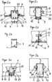
- the figure 2 shows further configurations of drywall composite supports made of a thin-walled sheet steel strip with the same thickness of the two sections.
- Figure 2a shows a wall cross-section with wall bodies (8) and intermediate plates (21) glued to it on the inside over the entire surface, for example as cement composite plates.
- the sheet metal reinforcement (5) is anchored positively to the wall bodies and intermediate plates in the undercut lateral recesses by means of a large number of flag-like sheet metal bends (6).
- the concrete penetrates through the profile openings into the wall body (8) and also acts on the narrow side flanks of the intermediate plates (21) and thus clamps them pressure-resistant between the drywall composite supports (1) arranged in the grid.
- the intermediate plates (21) are also acted upon from above by the concrete of the bar. This ensures the shear reinforcement of the wall and the profile reinforcement of the weak axis against buckling without further assembly steps and also improves the sound and fire protection of the wall.
- the sheet metal reinforcement (5) is made as a hollow profile with a protruding drywall contact surface (4) from a sheet metal strip of the same thickness by roll forming and has meander-shaped folded material concentrations for static reinforcement, which, as blocked and somewhat compressed ribs, increase the load-bearing capacity of the support and the steel-concrete Improve effective network.
- the Figure 2b shows only the cross section of a composite sheet of the drywall composite support (1) according to the invention made of thin-walled folded sheet metal reinforcement with continuous openings on all sides and sheet steel anchors (7) in the form of bent sheet metal lips (drains) on the sheet metal openings to secure the form-fitting active compound over the entire profile length.
- the material concentration of the sheet metal is adapted to the load.
- the sheet steel profile (3) and the sheet metal reinforcement (5) of the drywall composite column are made of the same sheet metal strip made of 0.7 mm thick galvanized sheet steel.
- the spatial distance between the drywall contact surface (4) and the surface of the support concrete is achieved by means of a positively inserted, volume-stable lightweight material backfill (9). Even after the concrete filling, this lightweight material (9) can Connection means are penetrated and also pierced by installations through the lateral installation openings (12).
- the active bond with the concrete is achieved by sheet steel anchors (7) in the form of a large number of openings with passages.
- the lateral recesses connect the wall bodies (4) to the composite concrete column after the concrete has been poured and prevent the enclosing sheet metal reinforcement from detaching from the column concrete.
- Figure 2d shows the cross section of infilling wall bodies (8) of a drywall composite column (1) and a simple sheet metal reinforcement (5) in connection with high-strength concrete as a splayed concrete composite column.
- the wall body is the sole formwork for the grouting concrete (23) of the composite concrete column.
- FIG 3a Sheet steel profile (3) and sheet metal reinforcement (5) are made from the same thin-walled semi-finished sheet metal strip.
- the sheet metal reinforcement (5) is in form-fitting relationship with the wall bodies (8) as formwork and with a coarse-meshed tubular lattice fabric (25) via alternately bent flanks.
- the coarse fabric consists of longitudinally reinforced carbon fibers that can be easily penetrated by the flowable concrete.
- the woven mesh hose can be easily manufactured in many dimensions and adapted to the load without tool costs, can be processed and assembled on site and is insensitive to corrosive environments.
- the lightweight material backfill (9) maintains the spatial distance between the drywall contact surface (4) and the concrete surface.
- the Figure 3b shows a rectangular hollow profile with a sheet metal thickness of 2 mm as sheet metal reinforcement (5) with a large number of local sheet steel anchors (7) in the form of openings with passages and a sheet steel profile (3) with a sheet metal thickness of 0.6 mm and an outer drywall contact surface (4) and a drywall contact surface (4) inside the wall.
- the sheet steel profile (3) is inserted in a form-fitting manner into the punched-out sections of the sheet metal reinforcement (5) and is permanently locked in place by the subsequent pouring of concrete.
- the inner wall drywall contact surface (4) is used for additional planking with building boards (13) for static reinforcement of the wall and/or to improve noise and fire protection.
- Figure 4a shows a drywall composite column (1) with a predominantly rectangular concrete cross-section and cambered enveloping surfaces made of enclosing sheet metal reinforcement on 3 sides and two sheet steel profile sections with drywall contact surfaces (4), which are made of a thin-walled semi-finished sheet metal strip with the same material thickness.
- a dimensionally stable lightweight material backfill (9) is inserted on one side of the support, which closes the support as formwork and at the same time forms the space behind the drywall contact surfaces (4) for fastening connections.
- the profile legs are held together by means of several U-bolts over the support height.
- the composite effect is primarily ensured by several rows of sheet steel anchors (7) in the form of "bridges" as a forming partial punching over the entire length and height of the support.
- the bridges are punched horizontally so that the sharp-edged sheet metal bends provide an anchor function on the concrete surface for the stresses along the steel profile. If the deflection is only slightly more than the material thickness of the steel sheet, then the function as concrete-tight formwork is still retained.
- a hardening thick coating (22) that can be brushed on from the outside is necessary to ensure a tight formwork, for example, in order to close the gaps in the sheet metal.
- a sleeve tube (24) has been inserted into the precisely pre-worked openings of the composite profile before the concrete is poured.
- several openings are pre-punched on the sheet metal profile, which can be broken out as required.
- Figure 4b shows a support with a round concrete cross-section with two drywall contact surfaces (4) and with a large number of sheet steel anchors (7) in the form of inner sharp-edged embossing over the entire height of the support to ensure the concrete bond. Due to the taut confinement of the concrete core, the sheet metal formwork cannot detach from the surface. At the central contact point of the sheet metal reinforcement (5), many individual sheet metal tabs engage in punched-out holes on the opposite side and are hooked by bending in such a way that a quasi-statically stable tube is created.
- the embodiment Figure 4c has continuous flag-like sheet metal bends (6) inwards (horizontally or vertically) in several rows with corresponding openings in the enveloping surface of the sheet metal reinforcement (5) for the active compound.
- the Bends have the shape of a trapezoidal surface and are anchored positively due to the longer inside and also force-fitting due to the adhesive bond on both sides in the concrete of the column.
- the circumference of the column is tightly wrapped in foil or fabric (22).
- At least one sheet steel profile (3) with at least one drywall contact surface (4) is hooked or connected in a form-fitting manner through the film covering in precisely fitting openings.
- the sheet metal reinforcement (5) of the composite concrete column (2) can also have local incisions for profile zones that can be bent or broken out, so that diagonal braces or struts can be inserted into the formwork from the outside.
- flag-like sheet metal bends (6) can exist inwards in order to clamp adjustment profiles in a precise position.
- Figure 4d The cross section of the composite concrete column (2) shows a perforated steel tube with a sheet thickness of 1.5 mm and a tight foil covering (22).
- the holes in the sheet metal reinforcement with a diameter of approx. 30 mm are large enough to act as sheet steel anchors (7).
- One or more thin-walled sheet steel profiles (3) with a sheet thickness of 0.6 mm and a flat contact surface (4) are subsequently inserted or hooked into the perforations on the composite concrete column (2) with a positive fit on the construction site through the foil using pointed and precisely fitting bends and permanently connected by the subsequent concrete casting.
Landscapes
- Engineering & Computer Science (AREA)
- Architecture (AREA)
- Civil Engineering (AREA)
- Structural Engineering (AREA)
- Physics & Mathematics (AREA)
- Electromagnetism (AREA)
- Building Environments (AREA)
- Load-Bearing And Curtain Walls (AREA)
- Finishing Walls (AREA)
- Manufacturing Of Tubular Articles Or Embedded Moulded Articles (AREA)
Applications Claiming Priority (2)
| Application Number | Priority Date | Filing Date | Title |
|---|---|---|---|
| DE102016012398 | 2016-10-17 | ||
| PCT/DE2017/000354 WO2018072777A1 (de) | 2016-10-17 | 2017-10-16 | Wandbausystem mit trockenbau-stahlprofil-beton-verbundstützen für den hausbau |
Publications (3)
| Publication Number | Publication Date |
|---|---|
| EP3526415A1 EP3526415A1 (de) | 2019-08-21 |
| EP3526415B1 true EP3526415B1 (de) | 2023-06-07 |
| EP3526415C0 EP3526415C0 (de) | 2023-06-07 |
Family
ID=60452321
Family Applications (1)
| Application Number | Title | Priority Date | Filing Date |
|---|---|---|---|
| EP17804049.9A Active EP3526415B1 (de) | 2016-10-17 | 2017-10-16 | Wandbausystem mit trockenbau-stahlprofil-beton-verbundstützen für den hausbau |
Country Status (8)
| Country | Link |
|---|---|
| US (1) | US10655327B2 (pl) |
| EP (1) | EP3526415B1 (pl) |
| CN (1) | CN110088412B (pl) |
| EA (1) | EA201990970A1 (pl) |
| ES (1) | ES2953518T3 (pl) |
| PL (1) | PL3526415T3 (pl) |
| UA (1) | UA125695C2 (pl) |
| WO (1) | WO2018072777A1 (pl) |
Families Citing this family (10)
| Publication number | Priority date | Publication date | Assignee | Title |
|---|---|---|---|---|
| JP7055593B2 (ja) * | 2017-01-27 | 2022-04-18 | ニチハ株式会社 | 建材、建材の積層体、及び建材の施工方法 |
| CN108999341B (zh) * | 2018-09-11 | 2023-06-23 | 深圳大学 | 咬合式钢-混凝土组合柱与柱连接节点及制作方法 |
| DE102019000116A1 (de) | 2019-01-11 | 2020-07-16 | HIB Huber Integral Bau GmbH | Konstruktive Stahlbauteile |
| CN112049283B (zh) * | 2020-09-28 | 2021-07-16 | 河北省第四建筑工程有限公司 | 保温外墙的施工方法及保温板固定装置 |
| CN112854525A (zh) * | 2021-01-13 | 2021-05-28 | 河南省予卓信息科技有限公司 | 一种建筑工程防水结构 |
| CN112900639B (zh) * | 2021-01-22 | 2022-06-28 | 中国建筑第八工程局有限公司 | 玻璃砖与加气混凝土砌块错位安装连接构件及其施工方法 |
| CN113958123B (zh) * | 2021-11-04 | 2023-04-07 | 中国十七冶集团有限公司 | 一种混凝土斜柱模板斜度控制装置的制造方法 |
| CN114658168B (zh) * | 2022-04-11 | 2023-05-09 | 四川农业大学 | 一种轻质高强预制构造柱结构 |
| EP4269007A1 (en) * | 2022-04-28 | 2023-11-01 | Stoyanov, Damian Vassilev | Slotting tool for cladding panels, method for slot milling into a cladding panel, cladding panel and method for fastening of cladding panels to a load-bearing subconstruction of building |
| CN121802971B (zh) * | 2026-03-09 | 2026-05-05 | 陕西安建投资建设有限公司 | 一种alc墙板端部预制构造柱结构及施工方法 |
Family Cites Families (21)
| Publication number | Priority date | Publication date | Assignee | Title |
|---|---|---|---|---|
| BE634614A (fr) * | 1963-07-08 | 1963-11-18 | Elément de construction | |
| FR900328A (fr) | 1943-07-31 | 1945-06-26 | Maison Metallique Grames | Procédé de construction de murs et cloisons de maisons en panneaux préfabriqués et éléments de construction pour sa mise en oeuvre |
| DE816143C (de) | 1949-10-25 | 1951-10-08 | Ver Westdeutsche Waggonfabrike | Loesbare Befestigung von plattenfoermigen Innenraumverkleidungen an gebaeudefesten Teilen |
| US2753962A (en) * | 1950-09-15 | 1956-07-10 | Robert K Mcberty | Metallic wall and roof joint |
| US3355852A (en) * | 1963-11-12 | 1967-12-05 | Fire Trol Corp | Fireproof building column assemblies |
| US4120131A (en) * | 1976-09-03 | 1978-10-17 | Carroll Research, Inc. | Building structure |
| US4484427A (en) * | 1982-03-08 | 1984-11-27 | Robert C. Crites | Method and apparatus for attaching furring to columns |
| US4541219A (en) * | 1983-07-22 | 1985-09-17 | Parker Alvin S | Clip for attaching sheets of wall material to columns and other structural members |
| US4841707A (en) * | 1987-01-05 | 1989-06-27 | Novoa Jose M | Composite double or multiple wall |
| CA1296501C (en) * | 1988-01-14 | 1992-03-03 | Herbert K. Schilger | Composite column or beam for building construction |
| DE4343465C2 (de) | 1993-12-20 | 1996-04-25 | Burkhart Schurig | Bewehrtes Leichtbaukonstruktionssystem |
| WO2000017461A1 (de) * | 1998-09-17 | 2000-03-30 | Burkhart Schurig | Schalungswand aus dämmstoff |
| DE20021603U1 (de) | 2000-12-21 | 2001-03-01 | Korte, Andrea, 58640 Iserlohn | Transportables Flächentragwerk |
| US20040068948A1 (en) | 2002-10-03 | 2004-04-15 | Wrass Lawrence J. | Fire/party wall system |
| DE102005026797A1 (de) | 2005-06-10 | 2006-12-14 | Wahls, Manfred, Dipl.-Ing. | Dämmstoff-Verbundwand |
| US7900411B2 (en) * | 2006-02-17 | 2011-03-08 | Antonic James P | Shear wall building assemblies |
| DE202010002389U1 (de) | 2010-02-16 | 2011-03-31 | Peters, Karl-Heinz | Gebäude in Skelettbauweise mit hoher Wärmedämmung |
| CN103104094B (zh) * | 2010-04-21 | 2015-04-15 | 成都绿建科技有限公司 | 一种格构轻钢房屋的施工方法 |
| CN101936074B (zh) * | 2010-08-05 | 2012-10-10 | 北京特希达科技有限公司 | 快捷房屋抗震加固方法及装置 |
| JP5839800B2 (ja) | 2011-01-05 | 2016-01-06 | 株式会社竹中工務店 | コンクリート充填鋼管柱 |
| US20150204067A1 (en) | 2012-06-29 | 2015-07-23 | Wolfgang Adolf Binder | Building system and method |
-
2017
- 2017-10-16 EA EA201990970A patent/EA201990970A1/ru unknown
- 2017-10-16 EP EP17804049.9A patent/EP3526415B1/de active Active
- 2017-10-16 CN CN201780077974.1A patent/CN110088412B/zh active Active
- 2017-10-16 WO PCT/DE2017/000354 patent/WO2018072777A1/de not_active Ceased
- 2017-10-16 US US16/342,190 patent/US10655327B2/en active Active
- 2017-10-16 ES ES17804049T patent/ES2953518T3/es active Active
- 2017-10-16 PL PL17804049.9T patent/PL3526415T3/pl unknown
- 2017-10-16 UA UAA201905039A patent/UA125695C2/uk unknown
Also Published As
| Publication number | Publication date |
|---|---|
| WO2018072777A1 (de) | 2018-04-26 |
| ES2953518T3 (es) | 2023-11-14 |
| EA201990970A1 (ru) | 2019-10-31 |
| US10655327B2 (en) | 2020-05-19 |
| US20190284802A1 (en) | 2019-09-19 |
| PL3526415T3 (pl) | 2023-10-16 |
| CN110088412B (zh) | 2021-09-21 |
| EP3526415A1 (de) | 2019-08-21 |
| UA125695C2 (uk) | 2022-05-18 |
| EP3526415C0 (de) | 2023-06-07 |
| CN110088412A (zh) | 2019-08-02 |
Similar Documents
| Publication | Publication Date | Title |
|---|---|---|
| WO2018072777A1 (de) | Wandbausystem mit trockenbau-stahlprofil-beton-verbundstützen für den hausbau | |
| DE2401794A1 (de) | Betonbewehrung | |
| DE10147831B4 (de) | Ständerwand | |
| EP3529426B1 (de) | Wandbausystem mit trockenbau-kombiprofilen und verfahren zum wandbau | |
| WO2008092664A2 (de) | Bauelement | |
| DE3128165A1 (de) | Schalldaemmendes wandbausystem fuer industriebauten, sowie kassettenprofil hierfuer | |
| DE102005026797A1 (de) | Dämmstoff-Verbundwand | |
| EP2284325A2 (de) | Gebäudewand mit einem stützgerüst | |
| EP2354344A2 (de) | Vorrichtung zum Anbringen eines von einem Gebäude vorkragenden Tragbalkens | |
| EP3754125B1 (de) | Bauelement zum einbau in trennfugen von gebäuden | |
| DE2503132A1 (de) | Verbundelemente fuer stahlbeton oder andere erhaertungsmassen | |
| DE2908995C2 (pl) | ||
| EP1972734A1 (de) | Fixierkörper für eine Dämmplatte | |
| EP1842984B1 (de) | Profiliertes Deckenrand-Abschalelement für Betondecken | |
| JP2013083063A (ja) | 鉄筋コンクリート構造物における既設の方立壁の補強方法 | |
| CH712684A2 (de) | Raumzellenelement. | |
| EP2871301B1 (de) | Verfahren und Trägerteil zur Anbringung von dämmenden Baumitteln an Gebäudewänden | |
| EP2450497A2 (de) | Armierter Betonstopfen und Verfahren zur Herstellung eines Beton-Holz-Verbundelements | |
| DE4000956A1 (de) | Element fuer den grosstafelbau aus beton | |
| DE20210919U1 (de) | Gebäudewand | |
| DE102012007700B4 (de) | Stahlbetondecke mit mindestens einer darauf befestigten Fußpfette | |
| EP1528173A2 (de) | Vorgespannte Flachdecke mit Hohldeckenplatten | |
| DE821403C (de) | Vorgefertigtes Bauelement und Verfahren zum Zusammenbau solcher Bauelemente | |
| DE2332560A1 (de) | Verfahren und vorrichtung zum bau mehrstoeckiger gebaeude mit vorgefertigten elementen | |
| DE810305C (de) | Armierter Baukoerper |
Legal Events
| Date | Code | Title | Description |
|---|---|---|---|
| STAA | Information on the status of an ep patent application or granted ep patent |
Free format text: STATUS: UNKNOWN |
|
| STAA | Information on the status of an ep patent application or granted ep patent |
Free format text: STATUS: THE INTERNATIONAL PUBLICATION HAS BEEN MADE |
|
| PUAI | Public reference made under article 153(3) epc to a published international application that has entered the european phase |
Free format text: ORIGINAL CODE: 0009012 |
|
| STAA | Information on the status of an ep patent application or granted ep patent |
Free format text: STATUS: REQUEST FOR EXAMINATION WAS MADE |
|
| 17P | Request for examination filed |
Effective date: 20190614 |
|
| AK | Designated contracting states |
Kind code of ref document: A1 Designated state(s): AL AT BE BG CH CY CZ DE DK EE ES FI FR GB GR HR HU IE IS IT LI LT LU LV MC MK MT NL NO PL PT RO RS SE SI SK SM TR |
|
| AX | Request for extension of the european patent |
Extension state: BA ME |
|
| DAV | Request for validation of the european patent (deleted) | ||
| DAX | Request for extension of the european patent (deleted) | ||
| GRAP | Despatch of communication of intention to grant a patent |
Free format text: ORIGINAL CODE: EPIDOSNIGR1 |
|
| STAA | Information on the status of an ep patent application or granted ep patent |
Free format text: STATUS: GRANT OF PATENT IS INTENDED |
|
| INTG | Intention to grant announced |
Effective date: 20220119 |
|
| GRAJ | Information related to disapproval of communication of intention to grant by the applicant or resumption of examination proceedings by the epo deleted |
Free format text: ORIGINAL CODE: EPIDOSDIGR1 |
|
| STAA | Information on the status of an ep patent application or granted ep patent |
Free format text: STATUS: REQUEST FOR EXAMINATION WAS MADE |
|
| GRAP | Despatch of communication of intention to grant a patent |
Free format text: ORIGINAL CODE: EPIDOSNIGR1 |
|
| STAA | Information on the status of an ep patent application or granted ep patent |
Free format text: STATUS: GRANT OF PATENT IS INTENDED |
|
| INTC | Intention to grant announced (deleted) | ||
| INTG | Intention to grant announced |
Effective date: 20220613 |
|
| GRAJ | Information related to disapproval of communication of intention to grant by the applicant or resumption of examination proceedings by the epo deleted |
Free format text: ORIGINAL CODE: EPIDOSDIGR1 |
|
| STAA | Information on the status of an ep patent application or granted ep patent |
Free format text: STATUS: REQUEST FOR EXAMINATION WAS MADE |
|
| INTC | Intention to grant announced (deleted) | ||
| GRAP | Despatch of communication of intention to grant a patent |
Free format text: ORIGINAL CODE: EPIDOSNIGR1 |
|
| STAA | Information on the status of an ep patent application or granted ep patent |
Free format text: STATUS: GRANT OF PATENT IS INTENDED |
|
| GRAS | Grant fee paid |
Free format text: ORIGINAL CODE: EPIDOSNIGR3 |
|
| INTG | Intention to grant announced |
Effective date: 20221205 |
|
| GRAA | (expected) grant |
Free format text: ORIGINAL CODE: 0009210 |
|
| STAA | Information on the status of an ep patent application or granted ep patent |
Free format text: STATUS: THE PATENT HAS BEEN GRANTED |
|
| AK | Designated contracting states |
Kind code of ref document: B1 Designated state(s): AL AT BE BG CH CY CZ DE DK EE ES FI FR GB GR HR HU IE IS IT LI LT LU LV MC MK MT NL NO PL PT RO RS SE SI SK SM TR |
|
| REG | Reference to a national code |
Ref country code: GB Ref legal event code: FG4D Free format text: NOT ENGLISH |
|
| REG | Reference to a national code |
Ref country code: CH Ref legal event code: EP Ref country code: AT Ref legal event code: REF Ref document number: 1575417 Country of ref document: AT Kind code of ref document: T Effective date: 20230615 Ref country code: DE Ref legal event code: R096 Ref document number: 502017014889 Country of ref document: DE |
|
| U01 | Request for unitary effect filed |
Effective date: 20230616 |
|
| U07 | Unitary effect registered |
Designated state(s): AT BE BG DE DK EE FI FR IT LT LU LV MT NL PT SE SI Effective date: 20230626 |
|
| REG | Reference to a national code |
Ref country code: LT Ref legal event code: MG9D |
|
| PG25 | Lapsed in a contracting state [announced via postgrant information from national office to epo] |
Ref country code: NO Free format text: LAPSE BECAUSE OF FAILURE TO SUBMIT A TRANSLATION OF THE DESCRIPTION OR TO PAY THE FEE WITHIN THE PRESCRIBED TIME-LIMIT Effective date: 20230907 |
|
| U20 | Renewal fee for the european patent with unitary effect paid |
Year of fee payment: 7 Effective date: 20231004 |
|
| REG | Reference to a national code |
Ref country code: ES Ref legal event code: FG2A Ref document number: 2953518 Country of ref document: ES Kind code of ref document: T3 Effective date: 20231114 |
|
| PG25 | Lapsed in a contracting state [announced via postgrant information from national office to epo] |
Ref country code: RS Free format text: LAPSE BECAUSE OF FAILURE TO SUBMIT A TRANSLATION OF THE DESCRIPTION OR TO PAY THE FEE WITHIN THE PRESCRIBED TIME-LIMIT Effective date: 20230607 Ref country code: HR Free format text: LAPSE BECAUSE OF FAILURE TO SUBMIT A TRANSLATION OF THE DESCRIPTION OR TO PAY THE FEE WITHIN THE PRESCRIBED TIME-LIMIT Effective date: 20230607 Ref country code: GR Free format text: LAPSE BECAUSE OF FAILURE TO SUBMIT A TRANSLATION OF THE DESCRIPTION OR TO PAY THE FEE WITHIN THE PRESCRIBED TIME-LIMIT Effective date: 20230908 |
|
| PG25 | Lapsed in a contracting state [announced via postgrant information from national office to epo] |
Ref country code: SK Free format text: LAPSE BECAUSE OF FAILURE TO SUBMIT A TRANSLATION OF THE DESCRIPTION OR TO PAY THE FEE WITHIN THE PRESCRIBED TIME-LIMIT Effective date: 20230607 |
|
| PG25 | Lapsed in a contracting state [announced via postgrant information from national office to epo] |
Ref country code: IS Free format text: LAPSE BECAUSE OF FAILURE TO SUBMIT A TRANSLATION OF THE DESCRIPTION OR TO PAY THE FEE WITHIN THE PRESCRIBED TIME-LIMIT Effective date: 20231007 |
|
| PG25 | Lapsed in a contracting state [announced via postgrant information from national office to epo] |
Ref country code: SM Free format text: LAPSE BECAUSE OF FAILURE TO SUBMIT A TRANSLATION OF THE DESCRIPTION OR TO PAY THE FEE WITHIN THE PRESCRIBED TIME-LIMIT Effective date: 20230607 Ref country code: SK Free format text: LAPSE BECAUSE OF FAILURE TO SUBMIT A TRANSLATION OF THE DESCRIPTION OR TO PAY THE FEE WITHIN THE PRESCRIBED TIME-LIMIT Effective date: 20230607 Ref country code: RO Free format text: LAPSE BECAUSE OF FAILURE TO SUBMIT A TRANSLATION OF THE DESCRIPTION OR TO PAY THE FEE WITHIN THE PRESCRIBED TIME-LIMIT Effective date: 20230607 Ref country code: IS Free format text: LAPSE BECAUSE OF FAILURE TO SUBMIT A TRANSLATION OF THE DESCRIPTION OR TO PAY THE FEE WITHIN THE PRESCRIBED TIME-LIMIT Effective date: 20231007 Ref country code: CZ Free format text: LAPSE BECAUSE OF FAILURE TO SUBMIT A TRANSLATION OF THE DESCRIPTION OR TO PAY THE FEE WITHIN THE PRESCRIBED TIME-LIMIT Effective date: 20230607 |
|
| REG | Reference to a national code |
Ref country code: DE Ref legal event code: R097 Ref document number: 502017014889 Country of ref document: DE |
|
| PLBE | No opposition filed within time limit |
Free format text: ORIGINAL CODE: 0009261 |
|
| STAA | Information on the status of an ep patent application or granted ep patent |
Free format text: STATUS: NO OPPOSITION FILED WITHIN TIME LIMIT |
|
| 26N | No opposition filed |
Effective date: 20240308 |
|
| PG25 | Lapsed in a contracting state [announced via postgrant information from national office to epo] |
Ref country code: MC Free format text: LAPSE BECAUSE OF FAILURE TO SUBMIT A TRANSLATION OF THE DESCRIPTION OR TO PAY THE FEE WITHIN THE PRESCRIBED TIME-LIMIT Effective date: 20230607 |
|
| PG25 | Lapsed in a contracting state [announced via postgrant information from national office to epo] |
Ref country code: IE Free format text: LAPSE BECAUSE OF NON-PAYMENT OF DUE FEES Effective date: 20231016 |
|
| PG25 | Lapsed in a contracting state [announced via postgrant information from national office to epo] |
Ref country code: IE Free format text: LAPSE BECAUSE OF NON-PAYMENT OF DUE FEES Effective date: 20231016 |
|
| U20 | Renewal fee for the european patent with unitary effect paid |
Year of fee payment: 8 Effective date: 20241007 |
|
| PG25 | Lapsed in a contracting state [announced via postgrant information from national office to epo] |
Ref country code: CY Free format text: LAPSE BECAUSE OF FAILURE TO SUBMIT A TRANSLATION OF THE DESCRIPTION OR TO PAY THE FEE WITHIN THE PRESCRIBED TIME-LIMIT; INVALID AB INITIO Effective date: 20171016 |
|
| PG25 | Lapsed in a contracting state [announced via postgrant information from national office to epo] |
Ref country code: HU Free format text: LAPSE BECAUSE OF FAILURE TO SUBMIT A TRANSLATION OF THE DESCRIPTION OR TO PAY THE FEE WITHIN THE PRESCRIBED TIME-LIMIT; INVALID AB INITIO Effective date: 20171016 |
|
| REG | Reference to a national code |
Ref country code: CH Ref legal event code: U11 Free format text: ST27 STATUS EVENT CODE: U-0-0-U10-U11 (AS PROVIDED BY THE NATIONAL OFFICE) Effective date: 20251101 |
|
| U20 | Renewal fee for the european patent with unitary effect paid |
Year of fee payment: 9 Effective date: 20250929 |
|
| PGFP | Annual fee paid to national office [announced via postgrant information from national office to epo] |
Ref country code: GB Payment date: 20251024 Year of fee payment: 9 |
|
| PGFP | Annual fee paid to national office [announced via postgrant information from national office to epo] |
Ref country code: TR Payment date: 20251014 Year of fee payment: 9 |
|
| PGFP | Annual fee paid to national office [announced via postgrant information from national office to epo] |
Ref country code: CH Payment date: 20251101 Year of fee payment: 9 |
|
| PGFP | Annual fee paid to national office [announced via postgrant information from national office to epo] |
Ref country code: PL Payment date: 20251008 Year of fee payment: 9 |
|
| PGFP | Annual fee paid to national office [announced via postgrant information from national office to epo] |
Ref country code: ES Payment date: 20251114 Year of fee payment: 9 |