EP3517345B1 - Elektrofahrzeugsteuerungsvorrichtung, steuerungsverfahren und steuerungssystem - Google Patents
Elektrofahrzeugsteuerungsvorrichtung, steuerungsverfahren und steuerungssystem Download PDFInfo
- Publication number
- EP3517345B1 EP3517345B1 EP17852807.1A EP17852807A EP3517345B1 EP 3517345 B1 EP3517345 B1 EP 3517345B1 EP 17852807 A EP17852807 A EP 17852807A EP 3517345 B1 EP3517345 B1 EP 3517345B1
- Authority
- EP
- European Patent Office
- Prior art keywords
- target wheel
- torque
- wheel
- slip
- control
- Prior art date
- Legal status (The legal status is an assumption and is not a legal conclusion. Google has not performed a legal analysis and makes no representation as to the accuracy of the status listed.)
- Active
Links
Images




Classifications
-
- B—PERFORMING OPERATIONS; TRANSPORTING
- B60—VEHICLES IN GENERAL
- B60L—PROPULSION OF ELECTRICALLY-PROPELLED VEHICLES; SUPPLYING ELECTRIC POWER FOR AUXILIARY EQUIPMENT OF ELECTRICALLY-PROPELLED VEHICLES; ELECTRODYNAMIC BRAKE SYSTEMS FOR VEHICLES IN GENERAL; MAGNETIC SUSPENSION OR LEVITATION FOR VEHICLES; MONITORING OPERATING VARIABLES OF ELECTRICALLY-PROPELLED VEHICLES; ELECTRIC SAFETY DEVICES FOR ELECTRICALLY-PROPELLED VEHICLES
- B60L15/00—Methods, circuits, or devices for controlling the traction-motor speed of electrically-propelled vehicles
- B60L15/20—Methods, circuits, or devices for controlling the traction-motor speed of electrically-propelled vehicles for control of the vehicle or its driving motor to achieve a desired performance, e.g. speed, torque, programmed variation of speed
-
- B—PERFORMING OPERATIONS; TRANSPORTING
- B60—VEHICLES IN GENERAL
- B60K—ARRANGEMENT OR MOUNTING OF PROPULSION UNITS OR OF TRANSMISSIONS IN VEHICLES; ARRANGEMENT OR MOUNTING OF PLURAL DIVERSE PRIME-MOVERS IN VEHICLES; AUXILIARY DRIVES FOR VEHICLES; INSTRUMENTATION OR DASHBOARDS FOR VEHICLES; ARRANGEMENTS IN CONNECTION WITH COOLING, AIR INTAKE, GAS EXHAUST OR FUEL SUPPLY OF PROPULSION UNITS IN VEHICLES
- B60K17/00—Arrangement or mounting of transmissions in vehicles
- B60K17/34—Arrangement or mounting of transmissions in vehicles for driving both front and rear wheels, e.g. four wheel drive vehicles
- B60K17/356—Arrangement or mounting of transmissions in vehicles for driving both front and rear wheels, e.g. four wheel drive vehicles having fluid or electric motor, for driving one or more wheels
-
- B—PERFORMING OPERATIONS; TRANSPORTING
- B60—VEHICLES IN GENERAL
- B60K—ARRANGEMENT OR MOUNTING OF PROPULSION UNITS OR OF TRANSMISSIONS IN VEHICLES; ARRANGEMENT OR MOUNTING OF PLURAL DIVERSE PRIME-MOVERS IN VEHICLES; AUXILIARY DRIVES FOR VEHICLES; INSTRUMENTATION OR DASHBOARDS FOR VEHICLES; ARRANGEMENTS IN CONNECTION WITH COOLING, AIR INTAKE, GAS EXHAUST OR FUEL SUPPLY OF PROPULSION UNITS IN VEHICLES
- B60K23/00—Arrangement or mounting of control devices for vehicle transmissions, or parts thereof, not otherwise provided for
- B60K23/08—Arrangement or mounting of control devices for vehicle transmissions, or parts thereof, not otherwise provided for for changing number of driven wheels, for switching from driving one axle to driving two or more axles
- B60K23/0808—Arrangement or mounting of control devices for vehicle transmissions, or parts thereof, not otherwise provided for for changing number of driven wheels, for switching from driving one axle to driving two or more axles for varying torque distribution between driven axles, e.g. by transfer clutch
-
- B—PERFORMING OPERATIONS; TRANSPORTING
- B60—VEHICLES IN GENERAL
- B60K—ARRANGEMENT OR MOUNTING OF PROPULSION UNITS OR OF TRANSMISSIONS IN VEHICLES; ARRANGEMENT OR MOUNTING OF PLURAL DIVERSE PRIME-MOVERS IN VEHICLES; AUXILIARY DRIVES FOR VEHICLES; INSTRUMENTATION OR DASHBOARDS FOR VEHICLES; ARRANGEMENTS IN CONNECTION WITH COOLING, AIR INTAKE, GAS EXHAUST OR FUEL SUPPLY OF PROPULSION UNITS IN VEHICLES
- B60K6/00—Arrangement or mounting of plural diverse prime-movers for mutual or common propulsion, e.g. hybrid propulsion systems comprising electric motors and internal combustion engines
- B60K6/20—Arrangement or mounting of plural diverse prime-movers for mutual or common propulsion, e.g. hybrid propulsion systems comprising electric motors and internal combustion engines the prime-movers consisting of electric motors and internal combustion engines, e.g. HEVs
- B60K6/50—Architecture of the driveline characterised by arrangement or kind of transmission units
- B60K6/52—Driving a plurality of drive axles, e.g. four-wheel drive
-
- B—PERFORMING OPERATIONS; TRANSPORTING
- B60—VEHICLES IN GENERAL
- B60L—PROPULSION OF ELECTRICALLY-PROPELLED VEHICLES; SUPPLYING ELECTRIC POWER FOR AUXILIARY EQUIPMENT OF ELECTRICALLY-PROPELLED VEHICLES; ELECTRODYNAMIC BRAKE SYSTEMS FOR VEHICLES IN GENERAL; MAGNETIC SUSPENSION OR LEVITATION FOR VEHICLES; MONITORING OPERATING VARIABLES OF ELECTRICALLY-PROPELLED VEHICLES; ELECTRIC SAFETY DEVICES FOR ELECTRICALLY-PROPELLED VEHICLES
- B60L3/00—Electric devices on electrically-propelled vehicles for safety purposes; Monitoring operating variables, e.g. speed, deceleration or energy consumption
- B60L3/10—Indicating wheel slip ; Correction of wheel slip
- B60L3/106—Indicating wheel slip ; Correction of wheel slip for maintaining or recovering the adhesion of the drive wheels
-
- B—PERFORMING OPERATIONS; TRANSPORTING
- B60—VEHICLES IN GENERAL
- B60T—VEHICLE BRAKE CONTROL SYSTEMS OR PARTS THEREOF; BRAKE CONTROL SYSTEMS OR PARTS THEREOF, IN GENERAL; ARRANGEMENT OF BRAKING ELEMENTS ON VEHICLES IN GENERAL; PORTABLE DEVICES FOR PREVENTING UNWANTED MOVEMENT OF VEHICLES; VEHICLE MODIFICATIONS TO FACILITATE COOLING OF BRAKES
- B60T8/00—Arrangements for adjusting wheel-braking force to meet varying vehicular or ground-surface conditions, e.g. limiting or varying distribution of braking force
- B60T8/17—Using electrical or electronic regulation means to control braking
- B60T8/175—Brake regulation specially adapted to prevent excessive wheel spin during vehicle acceleration, e.g. for traction control
-
- B—PERFORMING OPERATIONS; TRANSPORTING
- B60—VEHICLES IN GENERAL
- B60T—VEHICLE BRAKE CONTROL SYSTEMS OR PARTS THEREOF; BRAKE CONTROL SYSTEMS OR PARTS THEREOF, IN GENERAL; ARRANGEMENT OF BRAKING ELEMENTS ON VEHICLES IN GENERAL; PORTABLE DEVICES FOR PREVENTING UNWANTED MOVEMENT OF VEHICLES; VEHICLE MODIFICATIONS TO FACILITATE COOLING OF BRAKES
- B60T8/00—Arrangements for adjusting wheel-braking force to meet varying vehicular or ground-surface conditions, e.g. limiting or varying distribution of braking force
- B60T8/17—Using electrical or electronic regulation means to control braking
- B60T8/176—Brake regulation specially adapted to prevent excessive wheel slip during vehicle deceleration, e.g. ABS
- B60T8/1764—Regulation during travel on surface with different coefficients of friction, e.g. between left and right sides, mu-split or between front and rear
-
- B—PERFORMING OPERATIONS; TRANSPORTING
- B60—VEHICLES IN GENERAL
- B60T—VEHICLE BRAKE CONTROL SYSTEMS OR PARTS THEREOF; BRAKE CONTROL SYSTEMS OR PARTS THEREOF, IN GENERAL; ARRANGEMENT OF BRAKING ELEMENTS ON VEHICLES IN GENERAL; PORTABLE DEVICES FOR PREVENTING UNWANTED MOVEMENT OF VEHICLES; VEHICLE MODIFICATIONS TO FACILITATE COOLING OF BRAKES
- B60T8/00—Arrangements for adjusting wheel-braking force to meet varying vehicular or ground-surface conditions, e.g. limiting or varying distribution of braking force
- B60T8/17—Using electrical or electronic regulation means to control braking
- B60T8/176—Brake regulation specially adapted to prevent excessive wheel slip during vehicle deceleration, e.g. ABS
- B60T8/1766—Proportioning of brake forces according to vehicle axle loads, e.g. front to rear of vehicle
-
- B—PERFORMING OPERATIONS; TRANSPORTING
- B60—VEHICLES IN GENERAL
- B60T—VEHICLE BRAKE CONTROL SYSTEMS OR PARTS THEREOF; BRAKE CONTROL SYSTEMS OR PARTS THEREOF, IN GENERAL; ARRANGEMENT OF BRAKING ELEMENTS ON VEHICLES IN GENERAL; PORTABLE DEVICES FOR PREVENTING UNWANTED MOVEMENT OF VEHICLES; VEHICLE MODIFICATIONS TO FACILITATE COOLING OF BRAKES
- B60T8/00—Arrangements for adjusting wheel-braking force to meet varying vehicular or ground-surface conditions, e.g. limiting or varying distribution of braking force
- B60T8/17—Using electrical or electronic regulation means to control braking
- B60T8/176—Brake regulation specially adapted to prevent excessive wheel slip during vehicle deceleration, e.g. ABS
- B60T8/1769—Brake regulation specially adapted to prevent excessive wheel slip during vehicle deceleration, e.g. ABS specially adapted for vehicles having more than one driven axle, e.g. four-wheel drive vehicles
-
- B—PERFORMING OPERATIONS; TRANSPORTING
- B60—VEHICLES IN GENERAL
- B60L—PROPULSION OF ELECTRICALLY-PROPELLED VEHICLES; SUPPLYING ELECTRIC POWER FOR AUXILIARY EQUIPMENT OF ELECTRICALLY-PROPELLED VEHICLES; ELECTRODYNAMIC BRAKE SYSTEMS FOR VEHICLES IN GENERAL; MAGNETIC SUSPENSION OR LEVITATION FOR VEHICLES; MONITORING OPERATING VARIABLES OF ELECTRICALLY-PROPELLED VEHICLES; ELECTRIC SAFETY DEVICES FOR ELECTRICALLY-PROPELLED VEHICLES
- B60L2220/00—Electrical machine types; Structures or applications thereof
- B60L2220/40—Electrical machine applications
- B60L2220/42—Electrical machine applications with use of more than one motor
-
- B—PERFORMING OPERATIONS; TRANSPORTING
- B60—VEHICLES IN GENERAL
- B60L—PROPULSION OF ELECTRICALLY-PROPELLED VEHICLES; SUPPLYING ELECTRIC POWER FOR AUXILIARY EQUIPMENT OF ELECTRICALLY-PROPELLED VEHICLES; ELECTRODYNAMIC BRAKE SYSTEMS FOR VEHICLES IN GENERAL; MAGNETIC SUSPENSION OR LEVITATION FOR VEHICLES; MONITORING OPERATING VARIABLES OF ELECTRICALLY-PROPELLED VEHICLES; ELECTRIC SAFETY DEVICES FOR ELECTRICALLY-PROPELLED VEHICLES
- B60L2240/00—Control parameters of input or output; Target parameters
- B60L2240/40—Drive Train control parameters
- B60L2240/42—Drive Train control parameters related to electric machines
- B60L2240/423—Torque
-
- B—PERFORMING OPERATIONS; TRANSPORTING
- B60—VEHICLES IN GENERAL
- B60L—PROPULSION OF ELECTRICALLY-PROPELLED VEHICLES; SUPPLYING ELECTRIC POWER FOR AUXILIARY EQUIPMENT OF ELECTRICALLY-PROPELLED VEHICLES; ELECTRODYNAMIC BRAKE SYSTEMS FOR VEHICLES IN GENERAL; MAGNETIC SUSPENSION OR LEVITATION FOR VEHICLES; MONITORING OPERATING VARIABLES OF ELECTRICALLY-PROPELLED VEHICLES; ELECTRIC SAFETY DEVICES FOR ELECTRICALLY-PROPELLED VEHICLES
- B60L2240/00—Control parameters of input or output; Target parameters
- B60L2240/40—Drive Train control parameters
- B60L2240/46—Drive Train control parameters related to wheels
- B60L2240/465—Slip
-
- B—PERFORMING OPERATIONS; TRANSPORTING
- B60—VEHICLES IN GENERAL
- B60L—PROPULSION OF ELECTRICALLY-PROPELLED VEHICLES; SUPPLYING ELECTRIC POWER FOR AUXILIARY EQUIPMENT OF ELECTRICALLY-PROPELLED VEHICLES; ELECTRODYNAMIC BRAKE SYSTEMS FOR VEHICLES IN GENERAL; MAGNETIC SUSPENSION OR LEVITATION FOR VEHICLES; MONITORING OPERATING VARIABLES OF ELECTRICALLY-PROPELLED VEHICLES; ELECTRIC SAFETY DEVICES FOR ELECTRICALLY-PROPELLED VEHICLES
- B60L2240/00—Control parameters of input or output; Target parameters
- B60L2240/60—Navigation input
- B60L2240/64—Road conditions
- B60L2240/647—Surface situation of road, e.g. type of paving
-
- B—PERFORMING OPERATIONS; TRANSPORTING
- B60—VEHICLES IN GENERAL
- B60L—PROPULSION OF ELECTRICALLY-PROPELLED VEHICLES; SUPPLYING ELECTRIC POWER FOR AUXILIARY EQUIPMENT OF ELECTRICALLY-PROPELLED VEHICLES; ELECTRODYNAMIC BRAKE SYSTEMS FOR VEHICLES IN GENERAL; MAGNETIC SUSPENSION OR LEVITATION FOR VEHICLES; MONITORING OPERATING VARIABLES OF ELECTRICALLY-PROPELLED VEHICLES; ELECTRIC SAFETY DEVICES FOR ELECTRICALLY-PROPELLED VEHICLES
- B60L2260/00—Operating Modes
- B60L2260/20—Drive modes; Transition between modes
- B60L2260/28—Four wheel or all wheel drive
-
- B—PERFORMING OPERATIONS; TRANSPORTING
- B60—VEHICLES IN GENERAL
- B60T—VEHICLE BRAKE CONTROL SYSTEMS OR PARTS THEREOF; BRAKE CONTROL SYSTEMS OR PARTS THEREOF, IN GENERAL; ARRANGEMENT OF BRAKING ELEMENTS ON VEHICLES IN GENERAL; PORTABLE DEVICES FOR PREVENTING UNWANTED MOVEMENT OF VEHICLES; VEHICLE MODIFICATIONS TO FACILITATE COOLING OF BRAKES
- B60T2210/00—Detection or estimation of road or environment conditions; Detection or estimation of road shapes
- B60T2210/10—Detection or estimation of road conditions
- B60T2210/12—Friction
-
- B—PERFORMING OPERATIONS; TRANSPORTING
- B60—VEHICLES IN GENERAL
- B60T—VEHICLE BRAKE CONTROL SYSTEMS OR PARTS THEREOF; BRAKE CONTROL SYSTEMS OR PARTS THEREOF, IN GENERAL; ARRANGEMENT OF BRAKING ELEMENTS ON VEHICLES IN GENERAL; PORTABLE DEVICES FOR PREVENTING UNWANTED MOVEMENT OF VEHICLES; VEHICLE MODIFICATIONS TO FACILITATE COOLING OF BRAKES
- B60T2270/00—Further aspects of brake control systems not otherwise provided for
- B60T2270/20—ASR control systems
-
- B—PERFORMING OPERATIONS; TRANSPORTING
- B60—VEHICLES IN GENERAL
- B60T—VEHICLE BRAKE CONTROL SYSTEMS OR PARTS THEREOF; BRAKE CONTROL SYSTEMS OR PARTS THEREOF, IN GENERAL; ARRANGEMENT OF BRAKING ELEMENTS ON VEHICLES IN GENERAL; PORTABLE DEVICES FOR PREVENTING UNWANTED MOVEMENT OF VEHICLES; VEHICLE MODIFICATIONS TO FACILITATE COOLING OF BRAKES
- B60T2270/00—Further aspects of brake control systems not otherwise provided for
- B60T2270/20—ASR control systems
- B60T2270/202—ASR control systems for all-wheel drive vehicles
-
- B—PERFORMING OPERATIONS; TRANSPORTING
- B60—VEHICLES IN GENERAL
- B60W—CONJOINT CONTROL OF VEHICLE SUB-UNITS OF DIFFERENT TYPE OR DIFFERENT FUNCTION; CONTROL SYSTEMS SPECIALLY ADAPTED FOR HYBRID VEHICLES; ROAD VEHICLE DRIVE CONTROL SYSTEMS FOR PURPOSES NOT RELATED TO THE CONTROL OF A PARTICULAR SUB-UNIT
- B60W2720/00—Output or target parameters relating to overall vehicle dynamics
- B60W2720/40—Torque distribution
- B60W2720/403—Torque distribution between front and rear axle
-
- B—PERFORMING OPERATIONS; TRANSPORTING
- B60—VEHICLES IN GENERAL
- B60Y—INDEXING SCHEME RELATING TO ASPECTS CROSS-CUTTING VEHICLE TECHNOLOGY
- B60Y2300/00—Purposes or special features of road vehicle drive control systems
- B60Y2300/18—Propelling the vehicle
- B60Y2300/18175—Preventing, or responsive to skidding of wheels
-
- B—PERFORMING OPERATIONS; TRANSPORTING
- B60—VEHICLES IN GENERAL
- B60Y—INDEXING SCHEME RELATING TO ASPECTS CROSS-CUTTING VEHICLE TECHNOLOGY
- B60Y2400/00—Special features of vehicle units
- B60Y2400/82—Four wheel drive systems
-
- Y—GENERAL TAGGING OF NEW TECHNOLOGICAL DEVELOPMENTS; GENERAL TAGGING OF CROSS-SECTIONAL TECHNOLOGIES SPANNING OVER SEVERAL SECTIONS OF THE IPC; TECHNICAL SUBJECTS COVERED BY FORMER USPC CROSS-REFERENCE ART COLLECTIONS [XRACs] AND DIGESTS
- Y02—TECHNOLOGIES OR APPLICATIONS FOR MITIGATION OR ADAPTATION AGAINST CLIMATE CHANGE
- Y02T—CLIMATE CHANGE MITIGATION TECHNOLOGIES RELATED TO TRANSPORTATION
- Y02T10/00—Road transport of goods or passengers
- Y02T10/60—Other road transportation technologies with climate change mitigation effect
- Y02T10/62—Hybrid vehicles
-
- Y—GENERAL TAGGING OF NEW TECHNOLOGICAL DEVELOPMENTS; GENERAL TAGGING OF CROSS-SECTIONAL TECHNOLOGIES SPANNING OVER SEVERAL SECTIONS OF THE IPC; TECHNICAL SUBJECTS COVERED BY FORMER USPC CROSS-REFERENCE ART COLLECTIONS [XRACs] AND DIGESTS
- Y02—TECHNOLOGIES OR APPLICATIONS FOR MITIGATION OR ADAPTATION AGAINST CLIMATE CHANGE
- Y02T—CLIMATE CHANGE MITIGATION TECHNOLOGIES RELATED TO TRANSPORTATION
- Y02T10/00—Road transport of goods or passengers
- Y02T10/60—Other road transportation technologies with climate change mitigation effect
- Y02T10/64—Electric machine technologies in electromobility
-
- Y—GENERAL TAGGING OF NEW TECHNOLOGICAL DEVELOPMENTS; GENERAL TAGGING OF CROSS-SECTIONAL TECHNOLOGIES SPANNING OVER SEVERAL SECTIONS OF THE IPC; TECHNICAL SUBJECTS COVERED BY FORMER USPC CROSS-REFERENCE ART COLLECTIONS [XRACs] AND DIGESTS
- Y02—TECHNOLOGIES OR APPLICATIONS FOR MITIGATION OR ADAPTATION AGAINST CLIMATE CHANGE
- Y02T—CLIMATE CHANGE MITIGATION TECHNOLOGIES RELATED TO TRANSPORTATION
- Y02T10/00—Road transport of goods or passengers
- Y02T10/60—Other road transportation technologies with climate change mitigation effect
- Y02T10/72—Electric energy management in electromobility
-
- Y—GENERAL TAGGING OF NEW TECHNOLOGICAL DEVELOPMENTS; GENERAL TAGGING OF CROSS-SECTIONAL TECHNOLOGIES SPANNING OVER SEVERAL SECTIONS OF THE IPC; TECHNICAL SUBJECTS COVERED BY FORMER USPC CROSS-REFERENCE ART COLLECTIONS [XRACs] AND DIGESTS
- Y02—TECHNOLOGIES OR APPLICATIONS FOR MITIGATION OR ADAPTATION AGAINST CLIMATE CHANGE
- Y02T—CLIMATE CHANGE MITIGATION TECHNOLOGIES RELATED TO TRANSPORTATION
- Y02T90/00—Enabling technologies or technologies with a potential or indirect contribution to GHG emissions mitigation
- Y02T90/10—Technologies relating to charging of electric vehicles
- Y02T90/16—Information or communication technologies improving the operation of electric vehicles
Definitions
- the present invention relates to a control apparatus, a control method, and a control system for an electric vehicle.
- a control apparatus for an electric vehicle including an electric motor for front wheels and an electric motor for rear wheels eliminates or reduces a slip of the front wheels, and limits a torque to be output to the rear wheels according to a torque to be output to the front wheels, when the front wheels have slipped during four-wheel drive running (for example, PTL 1).
- An object of the present invention is to provide a control apparatus, a control method, and a control system for an electric vehicle that can prevent or reduce the unnecessary torque fluctuation on a wheel not targeted for slip control.
- a control apparatus for an electric vehicle limits a torque to be output to a non-target wheel according to a torque output to a target wheel targeted for slip control after the slip control is started, and updates a limit value of the torque to be output to the non-target wheel when a fluctuation range of the torque output to the target wheel falls within a predetermined range during the limitation.
- the unnecessary torque fluctuation on the wheel not targeted for the slip control can be prevented or reduced.
- Fig. 1 illustrates a configuration of a control system of an electric vehicle according to a first embodiment.
- An electric vehicle 1 includes a front motor 3, which outputs a torque to front-side wheels (hereinafter also referred to as front wheels) 2FL and 2FR. Power is transmitted between the front motor 3 and the front wheels 2FL and 2FR via a speed reducer 4, a differential 5, and front axles 6FL and 6FR.
- the electric vehicle 1 includes a rear motor 7, which outputs a torque to rear-side wheels (hereinafter also referred to as rear wheels) 2RL and 2Rr. Power is transmitted between the rear motor 7 and the rear wheels 2RL and 2RR via a speed reducer 8, a dog clutch 9, a differential 10, and rear axles 6RL and 6RR. When the dog clutch 9 is connected, the power is transmitted between the rear motor 7 and the rear wheels 2RL and 2RR.
- the wheels 2FL, 2FR, 2RL, and 2RR include wheel speed sensors 11FL, 11FR, 11RL, and 11RR, which detect wheel speeds, respectively.
- the front motor 3 includes a resolver 12, which detects the number of rotations of the motor.
- the rear motor 7 includes a resolver 13, which detects the number of rotations of the motor.
- the electric vehicle 1 includes a low-voltage battery 14 and a high-voltage battery 15.
- the low-voltage battery 14 is, for example, a lead battery.
- the high-voltage battery 15 is, for example, a lithium-ion battery or a nickel-hydride battery.
- the high-voltage battery 15 is charged by power with a voltage thereof boosted by a DC-DC converter 16.
- the electric vehicle 1 includes a vehicle control apparatus (a control unit) 17, a front motor control apparatus 18, a rear motor control apparatus 19, and a battery control apparatus 20.
- vehicle control apparatus a control unit
- Each of the control apparatuses 17, 18, 19, and 20 share information between them via a CAN bus 21.
- the vehicle control apparatus 17 inputs information from various kinds of sensors, and comprehensively controls the vehicle.
- the vehicle control apparatus 17 calculates a front requested torque that the front motor 3 should output according to requested torque distribution with respect to a requested torque according to, for example, an accelerator operation performed by a driver.
- a requested distribution torque is a requested value of a torque distribution ratio between the front wheels 2FL and 2FR and the rear wheels 2RL and 2RR, and is appropriately set according to a running state.
- the vehicle control apparatus 17 calculates a front requested torque that the rear motor 7 should output according to the requested torque distribution with respect to the requested torque.
- the front motor control apparatus 18 controls the power to be supplied to the front motor 3, based on the front requested torque.
- the rear motor control apparatus 19 controls the power to be supplied to the rear motor 7, based on the rear requested torque.
- the battery control apparatus 20 monitors a charged/discharged state of the high-voltage battery 15 and a battery cell forming the high-voltage battery 15.
- the battery control apparatus 20 calculates a battery requested torque limit value based on, for example, the charged/discharged state of the high-voltage battery 15.
- the battery requested torque limit value is an allowable maximum torque of each of the front motor 3 and the rear motor 7. For example, when a charged amount of the high-voltage battery 15 reduces, the battery requested torque limit value is set to a smaller value than usual.
- the vehicle control apparatus 17 When one of a wheel speed of the front wheels 2FL and 2FR (a front wheel speed) and a wheel speed of the rear wheels 2RL and 2RR (a rear wheel speed) exceeds a target wheel speed during four-wheel drive running, the vehicle control apparatus 17 performs slip control of eliminating or reducing a slip by controlling the torque to be output to this wheel (a target wheel).
- the motor torque is controlled in such a manner that the wheel speed of the target wheel is converged on the target wheel speed.
- the target wheel speed is a speed acquired by adding a predetermined offset value to a vehicle speed.
- the vehicle speed is a speed estimated from, for example, a detection signal of an acceleration sensor mounted on the electric vehicle 1.
- the vehicle control apparatus 17 performs torque limit control of limiting the torque to be output to a wheel (a non-target wheel) that is not the wheel targeted for the slip control between the front wheels 2FL and 2FR and the rear wheels 2RL and 2RR, after starting the slip control.
- the torque limit control according to the first embodiment the torque of the non-target wheel is limited based on the torque output to the wheel targeted for the slip control with the aim of preventing or reducing an unnecessary torque fluctuation on the wheel not targeted for the slip control.
- Fig. 2 is a block diagram for performing the slip control and the torque limit control by the vehicle control apparatus 17.
- the vehicle control apparatus 17 includes a road surface ⁇ estimation processing portion (a road surface ⁇ estimated value calculation portion) 22, a torque limit value calculation processing portion (a non-target wheel torque limit control portion) 23, and a slip control torque calculation processing portion (a target wheel slip control portion and a non-target wheel sleep control portion) 24.
- the road surface ⁇ estimation processing portion 22 calculates a front road surface ⁇ estimated value, which is a road surface frictional coefficient between the front wheels 2FL and 2FR and a road surface, and a rear road surface ⁇ estimated value, which is a road surface frictional coefficient between the rear wheels 2RL and 2RR and the road surface, based on the requested torque and a slip control torque, when a slip control ongoing flag, which indicates that the slip control is in progress, is set.
- the road surface ⁇ estimation processing portion 22 calculates the road surface ⁇ estimated value with use of the slip control torque for the wheel targeted for the slip control and with use of the requested torque and the requested torque distribution for the non-target wheel.
- the road surface ⁇ estimated value is calculated with use of the slip control torque.
- the road surface ⁇ estimation processing portion 22 recalculates and updates the road surface ⁇ estimated value when a fluctuation range of the torque of the wheel targeted for the slip control falls within a predetermined range (a road surface ⁇ estimated value calculation).
- the torque limit value calculation processing portion 23 includes a front torque limit value calculation processing portion 23a and a rear torque limit value calculation processing portion 23b.
- the front torque limit value calculation processing portion 23a calculates a front torque limit value based on the requested torque distribution and the rear road surface ⁇ estimated value when the slip control ongoing flag is set.
- the rear torque limit value calculation processing portion 23b calculates a rear torque limit value based on the requested torque distribution and the front road surface ⁇ estimated value when the slip control ongoing flag is set.
- the torque limit value is updated by peak-hold. More specifically, when updating the torque limit value, the torque limit value calculation processing portion 23 compares the torque limit value calculated from the current road surface ⁇ estimated value and the current torque limit value, and sets one of them that has a smaller absolute value as the torque limit value.
- the torque limit value calculation processing portion 23 determines the torque limit value by select-low between the calculated torque limit value and the current torque limit value when the vehicle is accelerated, and determines the torque limit value by select-high between the calculated torque limit value and the current torque limit value when the vehicle is decelerated.
- the vehicle control apparatus 17 controls the power to be supplied to the motor on the non-target wheel side based on the front torque limit value during the torque limit control (non-target wheel torque limit control). A specific method for calculating the front torque limit value and the rear torque limit value will be described below.
- the slip control torque calculation processing portion 24 includes a slip detection portion 24a, which sets or clears the slip control flag by comparing the front wheel speed and the rear wheel speed with the target wheel speed, i.e., detects a slip of each of the front wheels 2FL and 2FR and the rear wheels 2RL and 2RR.
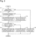
- Fig. 3 is a flowchart illustrating a method for calculating the torque limit value by the torque limit value calculation processing portion 23.
- step S1 the torque limit value calculation processing portion 23 determines whether the slip control ongoing flag is set. If the determination in step S1 is YES, the processing proceeds to step S2. If the determination in step S1 is NO, the processing proceeds to step S8.
- step S2 the torque limit value calculation processing portion 23 determines whether the slip control is in progress on both the front and rear wheels. If the determination in step S2 is YES, the processing proceeds to step S3. If the determination in step S2 is NO, the processing proceeds to step S4.
- step S3 the torque limit value calculation processing portion 23 selects a method that calculates the torque limit value by multiplying the road surface ⁇ estimated value by a predetermined gain as the method for calculating the torque limit value. A smaller value is acquired as the torque limit value determined in step S3 than the torque limit value determined in step S4, which will be described below, if the road surface ⁇ estimated value is the same.
- step S5 the torque limit value calculation processing portion 23 determines whether the front motor torque distribution is equal to or higher than the rear motor torque distribution. If the determination in step S5 is YES, the processing proceeds to step S6. If the determination in step S5 is NO, the processing proceeds to step S7.
- step S6 the torque limit value calculation processing portion 23 determines the torque limit value of the rear wheels 2RL and 2RR with use of the method selected in step S3 or step S4, based on the front road surface ⁇ estimated value.
- step S7 the torque limit value calculation processing portion 23 determines the torque limit value of the front wheels 2FL and 2FR with use of the method selected in step S3 or step S4, based on the rear road surface ⁇ estimated value.
- step S8 the torque limit value calculation processing portion 23 determines not to set the limit value for both the front and rear wheels.
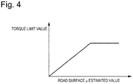
- Fig. 4 is a flowchart illustrating a method for calculating and updating the road surface ⁇ estimated value by the road surface ⁇ estimation processing portion 22.
- step S11 the road surface ⁇ estimation processing portion 22 determines whether a time elapsed after an end of the slip control is shorter than a predetermined time. If the determination in step S11 is YES, the processing proceeds to step S12. If the determination in step S11 is NO, the processing proceeds to step S19.
- step S12 the road surface ⁇ estimation processing portion 22 determines whether the slip control ongoing flag is set. If the determination in step S12 is YES, the processing proceeds to step S13. If the determination in step S12 is NO, the processing proceeds to step S18.
- step S13 the road surface ⁇ estimation processing portion 22 determines whether a difference between a torque instruction value according to the requested torque and the slip control torque is equal to or larger than a predetermined difference. If the determination in step S13 is YES, the processing proceeds to step S14. If the determination in step S13 is NO, the processing proceeds to step S18.
- step S14 the road surface ⁇ estimation processing portion 22 determines whether a predetermined time has elapsed since a start of the slip control. If the determination in step S14 is YES, the processing proceeds to step S15. If the determination in step S14 is NO, the processing proceeds to step S18.
- step S15 the road surface ⁇ estimation processing portion 22 determines whether the fluctuation range of the motor torque of the control target wheel falls within a predetermined range. If the determination in step S15 is YES, the processing proceeds to step S17. If the determination in step S15 is NO, the processing proceeds to step S16.
- the predetermined range is a range that allows the slip of the wheel targeted for the slip control to be determined to be sufficiently eliminated or reduced.
- step S16 the road surface ⁇ estimation processing portion 22 determines whether an immediately preceding cycle has been conducted during intervention by the slip control. If the determination in step S16 is YES, the processing proceeds to step S17. If the determination in step S16 is NO, the processing proceeds to RETURN.
- step S18 the road surface ⁇ estimation processing portion 22 holds the current road surface ⁇ estimated value.
- step S19 the road surface ⁇ estimation processing portion 22 updates the road surface ⁇ estimated value into a high ⁇ value (1.0).
- Fig. 6 is a timing chart in a case where the front wheels have slipped when the vehicle has started running according to the conventional control apparatus for the electric vehicle.
- the driver starts an accelerator operation.
- An increase in the accelerator operation amount causes increases in the front torque instruction value and the rear torque instruction value according thereto, thereby causing generation of the front motor torque and the rear motor torque.
- the conventional control apparatus for the electric vehicle constantly updates the torque limit value according to the change in the slip control torque, thereby raising a problem of occurrence of an unnecessary torque fluctuation in the rear motor torque and thus leading to unstable torque control on the rear wheels.
- Fig. 7 is a timing chart in a case where the front wheels 2FL and 2FR have slipped when the vehicle has started running according to the first embodiment.
- a period from time t0 to t2 is similar to the period from time t0 to time t2 illustrated in Fig. 6 , and therefore a description thereof will be omitted here.
- the front wheel speed exceeds the target wheel speed, so that the slip control and the torque limit control are started on the front wheels 2FL and 2FR and the rear wheels 2RL and 2RR, respectively.
- the torque limit value is determined based on the front road surface ⁇ estimated value estimated from the slip control torque at a slip control start time (t2).
- the front road surface ⁇ estimated value estimated at the slip control start time is maintained, and therefore the limit torque determined from the front road surface ⁇ estimated value is also kept constant.
- the predetermined time has elapsed since the slip control start time (t2) and the front motor torque is converged on the target wheel speed, so that the front road surface ⁇ estimated value is updated based on the slip control torque at time t3.
- the torque limit value is also updated according to the update of the front road surface ⁇ estimated value.
- a smaller value is acquired as the front road surface ⁇ estimated value estimated at time t3 than the front road surface ⁇ estimated value estimated at time t2, so that a smaller value is acquired as the torque limit value determined at time t3 than the torque limit value determined at time t2 and the rear motor is further limited.
- the vehicle control apparatus 17 can be prevented from calculating an excessively large torque limit value based the front road surface ⁇ estimated value transitionally reduced due to the slip control, thereby eliminating or reducing the slip of the rear wheels 2RL and 2RR.
- the vehicle control apparatus 17 does not update the torque limit value of the rear motor torque until the fluctuation range of the front motor torque falls within the predetermined range after starting the slip control. Due to this control, the vehicle control apparatus 17 can prevent the torque limit value from being dragged by the transitional change in the slip control torque. Therefore, the vehicle control apparatus 17 can prevent or reduce the unnecessary torque fluctuation on the rear wheels 2RL and 2RR during the slip control on the front wheels 2FL and 2FR. As a result, the vehicle control apparatus 17 can realize stable torque control on the rear wheels 2RL and 2RR.
- Fig. 8 is a timing chart in a case where the rear wheels 2RL and 2RR have slipped after the front wheels 2FL and 2FR have slipped when the vehicle has started running according to the first embodiment.
- a period from time t0 to t3 is similar to the period from time t0 to time t3 illustrated in Fig. 7 , and therefore a description thereof will be omitted here.
- the torque limit value of the rear wheels 2RL and 2RR is calculated before the slip control torque of the rear wheels 2RL and 2RR is calculated, and the slip control torque is limited to a value equal to or smaller than the torque limit value. Due to this control, the vehicle control apparatus 17 can avoid mutual intervention between the torque limit control and the slip control. As a result, the vehicle control apparatus 17 can prevent or reduce hunting of the torque control on the rear wheels 2RL and 2RR between the torque limit control and the slip control.
- the predetermined time has elapsed since the time of the start of the slip control on the front wheels 2FL and 2FR (t2) and the front motor torque is converged on the target wheel speed, so that the front road surface ⁇ estimated value is updated based on the slip control torque at time t4.
- the torque limit value is also updated according to the update of the front road surface ⁇ estimated value.
- the torque limit value is set to a smaller value than when the slip control is in progress on only the front wheels. As a result, the vehicle control apparatus 17 can prevent or reduce the continuation of the slip of the rear wheels 2RL and 2RR.
- Fig. 9 is a timing chart in a case where the front wheels 2FL and 2FR have slipped when the vehicle has slowed down according to the first embodiment.
- the torque limit value is determined based on the front road surface ⁇ estimated value estimated from the slip control torque at the slip control start time (t0).
- the front road surface ⁇ estimated value estimated at the slip control start time is maintained, and therefore the limit torque determined from the front road surface ⁇ estimated value is also kept constant.
- the predetermined time has elapsed since the slip control start time (t0) and the front motor torque is converged on the target wheel speed, so that the front road surface ⁇ estimated value is updated based on the slip control torque at time t2.
- the torque limit value is also updated according to the update of the front road surface ⁇ estimated value.
- Figs. 7 to 9 illustrate the example in which the slip control is performed on the front wheels 2FL and 2FR and the torque limit control is performed on the rear wheels 2RL and 2RR, but similar functions and effects can also be acquired when the slip control is performed on the rear wheels 2RL and 2RR and the slip control is performed on the front wheels 2FL and 2FR.
- a control apparatus for an electric vehicle including a front wheel, a front wheel electric motor configured to output a torque to the front wheel, a rear wheel, and a rear wheel electric motor configured to output a torque to the rear wheel
- a slip detection portion configured to detect a slip of each of the front wheel and the rear wheel
- a target wheel slip control portion configured to perform target wheel slip control of eliminating or reducing the slip of a target wheel by controlling the torque to be output to the target wheel when setting one of the front wheel and the rear wheel where a larger slip is detected by the slip detection portion as the target wheel targeted for slip control and setting the other of the front wheel and the rear wheel as a non-target wheel
- a non-target wheel torque limit control portion configured to perform non-target wheel torque limit control of limiting the torque to be output to the non-target wheel according to the torque output to the target wheel after the target wheel slip control is started and updating a limit value of the torque to be output to the non-target wheel when a fluctuation range of the torque output to the target wheel falls within
- the above-described configuration further includes a non-target wheel slip control portion configured to perform non-target wheel slip control of eliminating or reducing the slip of the non-target wheel by controlling the torque to be output to the non-target wheel when the slip of the non-target wheel exceeds the slip of the target wheel after the target wheel slip control is started.
- the non-target wheel torque limit control portion sets the limit value to a smaller value than the limit value set last time when updating the limit value.
- any of the above-described configurations further includes a road surface ⁇ estimated value calculation portion configured to calculate a road surface ⁇ estimated value based on the torque output to the target wheel, and recalculate and update the road surface ⁇ estimated value when the fluctuation range of the torque output to the target wheel falls within the predetermined range after the calculation.
- the non-target wheel torque limit control portion updates the limit value of the torque of the non-target wheel based on the update of the road surface ⁇ estimated value calculated by the road surface ⁇ estimated value calculation portion.
- the non-target wheel torque limit control portion conducts peak-hold regarding the limit value.
- the non-target wheel torque limit control portion makes the calculation for updating the limit value before the non-target wheel slip control portion makes the calculation for the non-target wheel slip control.
- the target wheel is the front wheel and the non-target wheel is the rear wheel.
- a control method for an electric vehicle including a front wheel, a front wheel electric motor configured to output a torque to the front wheel, a rear wheel, and a rear wheel electric motor configured to output a torque to the rear wheel includes a slip detection step of detecting a slip of each of the front wheel and the rear wheel; a target wheel slip control step of eliminating or reducing the slip of a target wheel by controlling the torque to be output to the target wheel when setting one of the front wheel and the rear wheel where a larger slip is detected by the slip detection step as the target wheel targeted for slip control and setting the other of the front wheel and the rear wheel as a non-target wheel; and a non-target wheel torque limit control step of performing non-target wheel torque limit control of limiting the torque to be output to the non-target wheel according to the torque output to the target wheel after the target wheel slip control step is started and updating a limit value of the torque to be output to the non-target wheel when a fluctuation range of the torque output to the target wheel falls within
- the above-described configuration further includes a non-target wheel slip control step of eliminating or reducing the slip of the non-target wheel by controlling the torque to be output to the non-target wheel when the slip of the non-target wheel exceeds the slip of the target wheel after the target wheel slip control step is started.
- the non-target wheel torque limit control step includes setting the limit value to a smaller value than the limit value set last time when updating the limit value.
- any of the above-described configurations further includes a road surface ⁇ estimated value calculation step of calculating a road surface ⁇ estimated value based on the torque output to the target wheel, and recalculating and updating the road surface ⁇ estimated value when the fluctuation range of the torque output to the target wheel falls within the predetermined range after the calculation.
- the non-target wheel torque limit control step includes updating the limit value of the torque of the non-target wheel based on the update of the road surface ⁇ estimated value calculated by the road surface ⁇ estimated value calculation.
- the non-target wheel torque limit control step includes conducting peak-hold regarding the limit value.
- the non-target wheel torque limit control step includes making the calculation for updating the limit value before the non-target wheel slip control step makes the calculation for the non-target wheel slip control.
- the target wheel is the front wheel and the non-target wheel is the rear wheel.
- the control unit includes a slip detection portion configured to detect a slip of each of the front wheel and the rear wheel, a target wheel slip control portion configured to perform target wheel slip control of eliminating or reducing the slip of a target wheel by controlling the torque to be output to the target wheel when setting one of the front wheel and the rear wheel where a larger slip is detected by the slip detection portion as the target wheel targeted for slip control and setting the other of the front wheel and the rear wheel as a non-target wheel, and a non-target wheel torque limit control portion configured to perform non-target wheel torque limit control of limiting the torque to be output to the non-target wheel according to the torque output to the target wheel after the target wheel slip control is started and updating a limit value of the torque to be output to the non-target wheel when a fluctuation range of the torque output to the target wheel falls within a predetermined range during the limitation.
Landscapes
- Engineering & Computer Science (AREA)
- Transportation (AREA)
- Mechanical Engineering (AREA)
- Chemical & Material Sciences (AREA)
- Combustion & Propulsion (AREA)
- Power Engineering (AREA)
- Life Sciences & Earth Sciences (AREA)
- Sustainable Development (AREA)
- Sustainable Energy (AREA)
- Electric Propulsion And Braking For Vehicles (AREA)
- Arrangement And Driving Of Transmission Devices (AREA)
Claims (12)
- Steuervorrichtung (17) für ein Elektrofahrzeug (1) mit einem Vorderrad (2FL, 2FR), einem Vorderrad-Elektromotor (3), der zum Ausgeben eines Drehmoments an das Vorderrad (2FL, 2FR) konfiguriert ist, einem Hinterrad (2RL), 2RR) und einen Hinterrad-Elektromotor (7), der zum Ausgeben eines Drehmoments an das Hinterrad (2RL, 2RR) konfiguriert ist, wobei die Steuervorrichtung (17) umfasst:einen Schlupferfassungsabschnitt (24a), der zum Erfassen einen Schlupf des Vorderrads (2FL, 2FR) sowie des Hinterrads (2RL, 2RR) konfiguriert ist;einen Zielrad-Schlupfsteuerabschnitt (24), der zum Ausführen einer Zielrad-Schlupfsteuerung zum Eliminieren oder Reduzieren des Schlupfs eines Zielrads durch Steuern des an das Zielrad auszugebenden Drehmoments konfiguriert ist, wenn entweder das Vorderrad (2FL, 2FR) oder das Hinterrad (2RL, 2RR), bei dem ein größerer Schlupf vom Schlupferfassungsabschnitt (24a) erfasst wird, als zur Schlupfsteuerung bestimmtes Zielrad eingestellt wird, und das jeweils andere, d. h, das Hinterrad (2RL, 2RR) oder das Vorderrad (2FL, 2FR), als Nicht-Zielrad eingestellt wird;einen Nicht-Zielrad-Drehmomentbegrenzung-Steuerabschnitt (23), der zum Ausführen einer Nicht-Zielrad-Drehmomentbegrenzungssteuerung, bei der das an das Nicht-Zielrad auszugebende Drehmoment gemäß dem an das Zielrad ausgegebenen Drehmoment begrenzt wird, nachdem die Zielrad-Schlupfsteuerung gestartet wurde, und zum Aktualisieren eines Grenzwerts des an das Nicht-Zielrad auszugebenden Drehmoments konfiguriert ist, wenn ein Schwankungsbereich des an das Zielrad ausgegebenen Drehmoments während der Begrenzung in einen vorbestimmten Bereich fällt; undeinen Schätzwert-Berechnungsabschnitt (22) für einen Straßenbelag µ, der zum Berechnen eines Schätzwerts eines Straßenbelags µ basierend auf dem an das Zielrad ausgegebenen Drehmoment, und zum Neuberechnen und Aktualisieren des Schätzwerts des Straßenbelags µ konfiguriert ist, wenn der Schwankungsbereich des an das Zielrad ausgegebenen Drehmoments nach der Berechnung in den vorbestimmten Bereich fällt, wobeider vorbestimmte Bereich ein Bereich ist, der es ermöglicht, den Schlupf des für die Schlupfregelung bestimmten Zielrades so zu ermitteln, dass dieser ausreichend eliminiert oder reduziert wird, undder Nicht-Zielrad-Drehmomentbegrenzung-Steuerabschnitt (23) den Grenzwert des Drehmoments des Nicht-Zielrads basierend auf der Aktualisierung des Schätzwerts des Straßenbelags µ, der vom Schätzwert-Berechnungsabschnitt (22) für einen Straßenbelag µ berechnet wurde, aktualisiert.
- Steuervorrichtung (17) für ein Elektrofahrzeug (1) nach Anspruch 1, ferner umfassend einen Nicht-Zielrad-Schlupfsteuerabschnitt (24), der zum Ausführen einer Nicht-Zielrad-Schlupfsteuerung zum Eliminieren und Reduzieren des Schlupfs des Nicht-Zielrads durch Steuern des an das Nicht-Zielrad auszugebenden Drehmoments konfiguriert ist, wenn der Schlupf des Nicht-Zielrads den Schlupf des Zielrads nach dem Starten der Zielrad-Schlupfsteuerung überschreitet.
- Steuervorrichtung (17) für ein Elektrofahrzeug (1) nach Anspruch 2, wobei der Nicht-Zielrad-Drehmomentbegrenzung-Steuerabschnitt (23) den Grenzwert auf einen kleineren Wert als den Grenzwert einstellt, der beim letzten Mal beim Aktualisieren des Grenzwerts eingestellt wurde.
- Steuervorrichtung (17) für ein Elektrofahrzeug (1) nach Anspruch 1, wobei der Nicht-Zielrad-Drehmomentbegrenzung-Steuerabschnitt (23) ein Spitzenhalten bezüglich des Grenzwerts durchführt.
- Steuervorrichtung (17) für ein Elektrofahrzeug (1) nach Anspruch 2, wobei der Nicht-Zielrad-Drehmomentbegrenzung-Steuerabschnitt (23) die Berechnung zum Aktualisieren des Grenzwerts ausführt, bevor der Nicht-Zielrad-Schlupfsteuerabschnitt (24) die Berechnung für die Nicht-Zielrad-Schlupfsteuerung ausführt.
- Steuervorrichtung (17) für ein Elektrofahrzeug (1) nach Anspruch 1, wobei das Zielrad das Vorderrad (2FL, 2FR) ist, und das Nicht-Zielrad das Hinterrad (2RL, 2RR) ist.
- Steuerverfahren für ein Elektrofahrzeug (1) mit einem Vorderrad (2FL, 2FR), einem Vorderrad-Elektromotor (3), der zum Ausgeben eines Drehmoments an das Vorderrad (2FL, 2FR) konfiguriert ist, einem Hinterrad (2RL, 2RR), und einem Hinterrad-Elektromotor (7), der zum Ausgeben eines Drehmoments an das Hinterrad (2RL, 2RR) konfiguriert ist, wobei das Steuerverfahren umfasst:einen Schlupferfassungsschritt zum Erfassen einen Schlupf des Vorderrads (2FL, 2FR) sowie des Hinterrads (2RL, 2RR);einen Zielrad-Schlupfsteuerschritt zum Eliminieren oder Reduzieren des Schlupfs eines Zielrads durch Steuern des an das Zielrad auszugebenden Drehmoments, wenn entweder das Vorderrad (2FL, 2FR) oder das Hinterrad (2RL, 2RR), bei dem ein größerer Schlupf vom Schlupferfassungsabschnitt (24a) erfasst wird, als zur Schlupfsteuerung bestimmtes Zielrad eingestellt wird, und das jeweils andere, d. h, das Hinterrad (2RL, 2RR) oder das Vorderrad (2FL, 2FR), als Nicht-Zielrad eingestellt wird;einen Nicht-Zielrad-Drehmomentbegrenzung-Steuerschritt zum Ausführen einer Nicht-Zielrad-Drehmomentbegrenzungssteuerung zum Begrenzen des an das Nicht-Zielrad auszugebenden Drehmoments gemäß dem an das Zielrad ausgegebenen Drehmoment, nachdem die Zielrad-Schlupfsteuerung gestartet wurde, und zum Aktualisieren eines Grenzwerts des an das Nicht-Zielrad auszugebenden Drehmoments, wenn ein Schwankungsbereich des an das Zielrad ausgegebenen Drehmoments während der Begrenzung in einen vorbestimmten Bereich fällt; undeinen Schätzwert-Berechnungsschritt für einen Straßenbelag µ zum Berechnen eines Schätzwerts eines Straßenbelags µ basierend auf dem an das Zielrad ausgegebenen Drehmoment, und zum Neuberechnen und Aktualisieren des Schätzwerts des Straßenbelags µ, wenn der Schwankungsbereich des an das Zielrad ausgegebenen Drehmoments nach der Berechnung in den vorbestimmten Bereich fällt, wobeider vorbestimmte Bereich ein Bereich ist, der es ermöglicht, den Schlupf des für die Schlupfregelung bestimmten Zielrads so zu ermitteln, dass dieser ausreichend eliminiert oder reduziert wird, undder Nicht-Zielrad-Drehmomentbegrenzung-Steuerschritt das Aktualisieren des Grenzwerts des Drehmoments des Nicht-Zielrads basierend auf der Aktualisierung des Schätzwerts des Straßenbelags µ, der vom Schätzwert-Berechnungsabschnitt (22) für einen Straßenbelag µ berechnet wurde, umfasst.
- Steuerverfahren für ein Elektrofahrzeug (1) nach Anspruch 7, ferner umfassend einen Nicht-Zielrad-Schlupfsteuerschritt zum Eliminieren oder Reduzieren des Schlupfs des Nicht-Zielrads durch Steuern des an das Nicht-Zielrad auszugebenden Drehmoments, wenn der Schlupf des Nicht-Zielrads den Schlupf des Zielrads überschreitet, nachdem der Schlupfsteuerschritt des Zielrads gestartet wurde.
- Steuerverfahren für ein Elektrofahrzeug (1) nach Anspruch 8, wobei der Nicht-Zielrad-Drehmomentbegrenzung-Steuerschritt das Einstellen des Grenzwerts auf einen kleineren Wert als den zuletzt beim Aktualisieren des Grenzwerts eingestellten Grenzwert umfasst.
- Steuerverfahren für ein Elektrofahrzeug (1) nach Anspruch 7, wobei der Nicht-Zielrad-Drehmomentbegrenzung-Steuerschritt das Durchführen eines Spitzenhaltens bezüglich des Grenzwerts umfasst.
- Steuerverfahren für ein Elektrofahrzeug (1) nach Anspruch 8, wobei der Zielrad-Drehmomentbegrenzung-Steuerschritt das Ausführen der Berechnung zum Aktualisieren des Grenzwerts umfasst, bevor der Nicht-Zielrad-Schlupfsteuerschritt die Berechnung für die Nicht-Zielrad-Schlupfsteuerung ausführt.
- Steuerverfahren für ein Elektrofahrzeug (1) nach Anspruch 7, wobei das Zielrad das Vorderrad (2FL, 2FR) ist, und das Nicht-Zielrad das Hinterrad (2RL, 2RR) ist.
Applications Claiming Priority (2)
| Application Number | Priority Date | Filing Date | Title |
|---|---|---|---|
| JP2016185106A JP6776502B2 (ja) | 2016-09-23 | 2016-09-23 | 電動車両の制御装置、制御方法および制御システム |
| PCT/JP2017/031704 WO2018056028A1 (ja) | 2016-09-23 | 2017-09-04 | 電動車両の制御装置、制御方法および制御システム |
Publications (3)
| Publication Number | Publication Date |
|---|---|
| EP3517345A1 EP3517345A1 (de) | 2019-07-31 |
| EP3517345A4 EP3517345A4 (de) | 2019-08-21 |
| EP3517345B1 true EP3517345B1 (de) | 2020-11-11 |
Family
ID=61690413
Family Applications (1)
| Application Number | Title | Priority Date | Filing Date |
|---|---|---|---|
| EP17852807.1A Active EP3517345B1 (de) | 2016-09-23 | 2017-09-04 | Elektrofahrzeugsteuerungsvorrichtung, steuerungsverfahren und steuerungssystem |
Country Status (5)
| Country | Link |
|---|---|
| US (1) | US11267345B2 (de) |
| EP (1) | EP3517345B1 (de) |
| JP (1) | JP6776502B2 (de) |
| CN (1) | CN109863057B (de) |
| WO (1) | WO2018056028A1 (de) |
Families Citing this family (13)
| Publication number | Priority date | Publication date | Assignee | Title |
|---|---|---|---|---|
| DE102017008949A1 (de) * | 2017-09-25 | 2019-03-28 | Lucas Automotive Gmbh | Radschlupfregelung für ein Kraftfahrzeug |
| GB2571331B (en) | 2018-02-26 | 2021-06-23 | Jaguar Land Rover Ltd | BEV torque split control |
| CN108749646A (zh) * | 2018-05-14 | 2018-11-06 | 山东理工大学 | 一种双电机电动汽车驱动转矩分配方法 |
| CN113573941B (zh) * | 2019-03-13 | 2023-07-18 | 三菱自动车工业株式会社 | 车辆控制装置 |
| KR102726794B1 (ko) * | 2019-08-07 | 2024-11-05 | 현대자동차주식회사 | 차량의 자세 제어 방법 |
| CN110635184B (zh) * | 2019-10-11 | 2022-09-09 | 联方云天科技(珠海)有限公司 | 一种具有多层管理体系和结构的模块化电池系统 |
| JP2021164365A (ja) * | 2020-04-02 | 2021-10-11 | 株式会社Subaru | 車両用制御装置 |
| US11932138B2 (en) * | 2020-10-28 | 2024-03-19 | Nissan Motor Co., Ltd. | Electric vehicle control method and electric vehicle control system |
| CN112895911B (zh) * | 2020-11-10 | 2022-08-30 | 长城汽车股份有限公司 | 湿滑路面扭矩控制的方法、装置及终端设备 |
| CN113060119B (zh) * | 2021-04-08 | 2022-04-12 | 中国第一汽车股份有限公司 | 一种分动器防滑控制方法 |
| US12233845B2 (en) * | 2022-05-02 | 2025-02-25 | GM Global Technology Operations LLC | Control system and method for mitigating driveline torque spikes in electric vehicles |
| US20240051546A1 (en) * | 2022-08-12 | 2024-02-15 | Ford Global Technologies, Llc | System for operating off-road electric vehicles |
| EP4653243A4 (de) * | 2023-01-16 | 2026-04-15 | Mitsubishi Motors Corp | Fahrsteuerungsvorrichtung für ein fahrzeug |
Citations (4)
| Publication number | Priority date | Publication date | Assignee | Title |
|---|---|---|---|---|
| JP3196526B2 (ja) * | 1994-09-29 | 2001-08-06 | トヨタ自動車株式会社 | 車輌の挙動制御装置 |
| JP2005207953A (ja) * | 2004-01-23 | 2005-08-04 | Toyota Motor Corp | 路面摩擦係数検出装置 |
| WO2012086223A1 (ja) * | 2010-12-24 | 2012-06-28 | 株式会社ユニバンス | 電気自動車 |
| EP2479076A1 (de) * | 2009-09-15 | 2012-07-25 | Hitachi Automotive Systems, Ltd. | Antriebssteuervorrichtung |
Family Cites Families (28)
| Publication number | Priority date | Publication date | Assignee | Title |
|---|---|---|---|---|
| JPH084371Y2 (ja) * | 1989-07-13 | 1996-02-07 | 本田技研工業株式会社 | 車両の駆動輪過剰スリップ防止装置 |
| JP3617680B2 (ja) * | 1995-01-31 | 2005-02-09 | 富士重工業株式会社 | 4輪駆動車のトラクション制御装置 |
| JP3681786B2 (ja) * | 1995-05-01 | 2005-08-10 | 本田技研工業株式会社 | 前後輪駆動車両 |
| KR0170514B1 (ko) * | 1995-11-22 | 1999-03-30 | 김광호 | 승압 전원을 갖는 반도체 메모리 장치 |
| JPH10119742A (ja) * | 1996-10-21 | 1998-05-12 | Toyota Motor Corp | 制動力配分制御装置 |
| JP4227723B2 (ja) * | 2000-08-25 | 2009-02-18 | トヨタ自動車株式会社 | 4輪駆動電気自動車およびその制御方法 |
| SE524087C2 (sv) * | 2002-10-31 | 2004-06-22 | Nira Dynamics Ab Mjaerdevi Sci | Metod för bestämning av friktionen mellan en yta och ett däck för vägfordon som drivs med alla hjul samt en transmissionskoppling för fördelning av ett vridmoment mellan hjulaxlar innefattande nämnda metod |
| US6909959B2 (en) * | 2003-03-07 | 2005-06-21 | Stephen James Hallowell | Torque distribution systems and methods for wheeled vehicles |
| JP4089608B2 (ja) * | 2003-12-08 | 2008-05-28 | トヨタ自動車株式会社 | 自動車 |
| JP2010051136A (ja) * | 2008-08-25 | 2010-03-04 | Tokyo Metropolitan Univ | 環境対策車及びその駆動力制御方法 |
| US7739005B1 (en) * | 2009-02-26 | 2010-06-15 | Tesla Motors, Inc. | Control system for an all-wheel drive electric vehicle |
| US8285465B2 (en) * | 2009-06-30 | 2012-10-09 | Robert Bosch Gmbh | Cooperative traction control system using dual slip controllers |
| JP4872007B2 (ja) * | 2010-03-23 | 2012-02-08 | 公益財団法人鉄道総合技術研究所 | 電動機制御装置及び再粘着制御方法 |
| WO2011132335A1 (ja) * | 2010-04-20 | 2011-10-27 | 株式会社ユニバンス | 電気自動車、制動プログラム、並びに電気自動車の制御装置および制御方法 |
| WO2013076902A1 (ja) * | 2011-11-25 | 2013-05-30 | 日産自動車株式会社 | 車両用駆動制御装置、車両用駆動制御方法 |
| JP5835583B2 (ja) * | 2012-04-27 | 2015-12-24 | 三菱自動車工業株式会社 | 電動車両の駆動力制御装置 |
| JP5884910B2 (ja) * | 2012-08-01 | 2016-03-15 | 日産自動車株式会社 | 車両用駆動制御装置 |
| EP2982538A4 (de) * | 2013-04-01 | 2017-03-08 | Pioneer Corporation | Antriebsregelungsvorrichtung und antriebsregelungsverfahren |
| JP6201209B2 (ja) * | 2013-09-12 | 2017-09-27 | 日立オートモティブシステムズ株式会社 | 駆動力制御装置及び駆動力制御方法 |
| JP6167363B2 (ja) * | 2013-09-12 | 2017-07-26 | 日立オートモティブシステムズ株式会社 | 電動車両の制御装置及び電動車両の制御方法 |
| CN105612080B (zh) * | 2013-10-09 | 2019-07-12 | 伊顿智能动力有限公司 | 用于限制离合器转矩以减小高mu车轮打滑的方法 |
| DE112013007547T5 (de) * | 2013-10-31 | 2016-07-21 | Mitsubishi Electric Corporation | Traktionssteuervorrichtung |
| DE102015000216A1 (de) * | 2014-03-11 | 2015-09-17 | Wabco Gmbh | Verfahren zur Ansteuerung von E-Motoren bei seriellen Hybridfahrzeugen oder vollelektrischen Fahrzeugen mit mindestens zwei separat angetriebenen Achsen |
| JP5883490B1 (ja) * | 2014-09-30 | 2016-03-15 | 富士重工業株式会社 | 車両の制御装置及び車両の制御方法 |
| CN104827932B (zh) * | 2014-10-17 | 2017-10-03 | 北京车和家信息技术有限责任公司 | 车辆的电机扭矩控制方法及系统 |
| JP2016086536A (ja) * | 2014-10-27 | 2016-05-19 | 日産自動車株式会社 | 車両のトラクション制御装置 |
| JP6183333B2 (ja) * | 2014-11-07 | 2017-08-23 | トヨタ自動車株式会社 | ハイブリッド自動車 |
| JP6380055B2 (ja) * | 2014-11-28 | 2018-08-29 | 株式会社ジェイテクト | 四輪駆動車の制御装置 |
-
2016
- 2016-09-23 JP JP2016185106A patent/JP6776502B2/ja active Active
-
2017
- 2017-09-04 EP EP17852807.1A patent/EP3517345B1/de active Active
- 2017-09-04 WO PCT/JP2017/031704 patent/WO2018056028A1/ja not_active Ceased
- 2017-09-04 US US16/330,786 patent/US11267345B2/en active Active
- 2017-09-04 CN CN201780057342.9A patent/CN109863057B/zh active Active
Patent Citations (4)
| Publication number | Priority date | Publication date | Assignee | Title |
|---|---|---|---|---|
| JP3196526B2 (ja) * | 1994-09-29 | 2001-08-06 | トヨタ自動車株式会社 | 車輌の挙動制御装置 |
| JP2005207953A (ja) * | 2004-01-23 | 2005-08-04 | Toyota Motor Corp | 路面摩擦係数検出装置 |
| EP2479076A1 (de) * | 2009-09-15 | 2012-07-25 | Hitachi Automotive Systems, Ltd. | Antriebssteuervorrichtung |
| WO2012086223A1 (ja) * | 2010-12-24 | 2012-06-28 | 株式会社ユニバンス | 電気自動車 |
Also Published As
| Publication number | Publication date |
|---|---|
| CN109863057B (zh) | 2022-09-09 |
| JP2018050413A (ja) | 2018-03-29 |
| EP3517345A1 (de) | 2019-07-31 |
| EP3517345A4 (de) | 2019-08-21 |
| CN109863057A (zh) | 2019-06-07 |
| US20190193577A1 (en) | 2019-06-27 |
| WO2018056028A1 (ja) | 2018-03-29 |
| US11267345B2 (en) | 2022-03-08 |
| JP6776502B2 (ja) | 2020-10-28 |
Similar Documents
| Publication | Publication Date | Title |
|---|---|---|
| EP3517345B1 (de) | Elektrofahrzeugsteuerungsvorrichtung, steuerungsverfahren und steuerungssystem | |
| US11878674B2 (en) | Estimation of vehicle speed in all-wheel-drive vehicle | |
| EP3368367B1 (de) | Elektrofahrzeug und aktives sicherheitssteuerungssystem und -verfahren dafür | |
| EP3213971B1 (de) | Elektrofahrzeug und aktives sicherheitskontrollsystem für elektrisches fahrzeug und steuerungsverfahren dafür | |
| EP3919312A1 (de) | Elektrofahrzeugsteuerungsvorrichtung, steuerungsverfahren und steuerungssystem | |
| CN108025651A (zh) | 具有制动系统的电动车辆以及用于制动系统的方法、控制器和计算机程序 | |
| EP3666582A1 (de) | Fahrzeugsteuerungsvorrichtung, fahrzeugsteuerungssystem und fahrzeugsteuerungsverfahren | |
| DE102014003992B4 (de) | System und Verfahren zur Antriebs- und Bremsmomentregelung in Elektrofahrzeugen mit Einzelradantrieb | |
| US20150274033A1 (en) | Wheel control device, vehicle, and wheel control method | |
| EP3231657B1 (de) | Vorrichtung zur brems-/antriebsleistungssteuerung und verfahren zur brems-/antriebsleistungssteuerung | |
| WO2015151193A1 (ja) | 車両のトラクション制御装置 | |
| US20200369157A1 (en) | Adjusting device for an electrically operated utility vehicle and method for the operation thereof | |
| KR102326629B1 (ko) | 전기 구동 시스템의 트랙션 제어를 위한 제어 장치 및 방법 | |
| JP6809661B2 (ja) | 電動車両の制御装置、電動車両の制御方法および電動車両の制御システム | |
| JPH03558A (ja) | 車輪速度処理装置 | |
| JP3713893B2 (ja) | 車両のヨーイング運動量制御装置 | |
| JP6774250B2 (ja) | 車両の制動力制御装置 | |
| US12304320B2 (en) | Vehicle control apparatus | |
| US8818667B2 (en) | Method for producing a differential torque acting on the vehicle wheels of a vehicle | |
| JP5018320B2 (ja) | 車両用走行制御装置及びその方法 | |
| JP6788424B2 (ja) | 車両の制動力制御装置 | |
| JP6948884B2 (ja) | 車両の制御装置、車両の制御システムおよび車両の制御方法 | |
| JP2023021494A (ja) | 車両制御装置、車両制御方法および車両制御システム | |
| JPH04110262A (ja) | アンチスキツド制御装置 | |
| JPH04237660A (ja) | アンチスキッド制御装置 |
Legal Events
| Date | Code | Title | Description |
|---|---|---|---|
| STAA | Information on the status of an ep patent application or granted ep patent |
Free format text: STATUS: THE INTERNATIONAL PUBLICATION HAS BEEN MADE |
|
| PUAI | Public reference made under article 153(3) epc to a published international application that has entered the european phase |
Free format text: ORIGINAL CODE: 0009012 |
|
| STAA | Information on the status of an ep patent application or granted ep patent |
Free format text: STATUS: REQUEST FOR EXAMINATION WAS MADE |
|
| 17P | Request for examination filed |
Effective date: 20190306 |
|
| AK | Designated contracting states |
Kind code of ref document: A1 Designated state(s): AL AT BE BG CH CY CZ DE DK EE ES FI FR GB GR HR HU IE IS IT LI LT LU LV MC MK MT NL NO PL PT RO RS SE SI SK SM TR |
|
| AX | Request for extension of the european patent |
Extension state: BA ME |
|
| A4 | Supplementary search report drawn up and despatched |
Effective date: 20190719 |
|
| RIC1 | Information provided on ipc code assigned before grant |
Ipc: B60L 3/10 20060101ALI20190715BHEP Ipc: B60T 8/1764 20060101ALI20190715BHEP Ipc: B60L 15/20 20060101AFI20190715BHEP Ipc: B60K 6/52 20071001ALI20190715BHEP Ipc: B60T 8/1769 20060101ALI20190715BHEP Ipc: B60T 8/175 20060101ALI20190715BHEP Ipc: B60T 8/1766 20060101ALI20190715BHEP |
|
| DAV | Request for validation of the european patent (deleted) | ||
| DAX | Request for extension of the european patent (deleted) | ||
| RIC1 | Information provided on ipc code assigned before grant |
Ipc: B60K 6/52 20071001ALI20200506BHEP Ipc: B60L 15/20 20060101AFI20200506BHEP Ipc: B60L 3/10 20060101ALI20200506BHEP Ipc: B60T 8/1766 20060101ALI20200506BHEP Ipc: B60T 8/1769 20060101ALI20200506BHEP Ipc: B60T 8/1764 20060101ALI20200506BHEP Ipc: B60T 8/175 20060101ALI20200506BHEP |
|
| GRAP | Despatch of communication of intention to grant a patent |
Free format text: ORIGINAL CODE: EPIDOSNIGR1 |
|
| STAA | Information on the status of an ep patent application or granted ep patent |
Free format text: STATUS: GRANT OF PATENT IS INTENDED |
|
| INTG | Intention to grant announced |
Effective date: 20200617 |
|
| GRAS | Grant fee paid |
Free format text: ORIGINAL CODE: EPIDOSNIGR3 |
|
| GRAA | (expected) grant |
Free format text: ORIGINAL CODE: 0009210 |
|
| STAA | Information on the status of an ep patent application or granted ep patent |
Free format text: STATUS: THE PATENT HAS BEEN GRANTED |
|
| AK | Designated contracting states |
Kind code of ref document: B1 Designated state(s): AL AT BE BG CH CY CZ DE DK EE ES FI FR GB GR HR HU IE IS IT LI LT LU LV MC MK MT NL NO PL PT RO RS SE SI SK SM TR |
|
| REG | Reference to a national code |
Ref country code: GB Ref legal event code: FG4D |
|
| REG | Reference to a national code |
Ref country code: CH Ref legal event code: EP |
|
| REG | Reference to a national code |
Ref country code: AT Ref legal event code: REF Ref document number: 1333126 Country of ref document: AT Kind code of ref document: T Effective date: 20201115 |
|
| REG | Reference to a national code |
Ref country code: DE Ref legal event code: R096 Ref document number: 602017027550 Country of ref document: DE |
|
| REG | Reference to a national code |
Ref country code: IE Ref legal event code: FG4D |
|
| REG | Reference to a national code |
Ref country code: NL Ref legal event code: MP Effective date: 20201111 |
|
| REG | Reference to a national code |
Ref country code: AT Ref legal event code: MK05 Ref document number: 1333126 Country of ref document: AT Kind code of ref document: T Effective date: 20201111 |
|
| PG25 | Lapsed in a contracting state [announced via postgrant information from national office to epo] |
Ref country code: GR Free format text: LAPSE BECAUSE OF FAILURE TO SUBMIT A TRANSLATION OF THE DESCRIPTION OR TO PAY THE FEE WITHIN THE PRESCRIBED TIME-LIMIT Effective date: 20210212 Ref country code: NO Free format text: LAPSE BECAUSE OF FAILURE TO SUBMIT A TRANSLATION OF THE DESCRIPTION OR TO PAY THE FEE WITHIN THE PRESCRIBED TIME-LIMIT Effective date: 20210211 Ref country code: RS Free format text: LAPSE BECAUSE OF FAILURE TO SUBMIT A TRANSLATION OF THE DESCRIPTION OR TO PAY THE FEE WITHIN THE PRESCRIBED TIME-LIMIT Effective date: 20201111 Ref country code: PT Free format text: LAPSE BECAUSE OF FAILURE TO SUBMIT A TRANSLATION OF THE DESCRIPTION OR TO PAY THE FEE WITHIN THE PRESCRIBED TIME-LIMIT Effective date: 20210311 Ref country code: FI Free format text: LAPSE BECAUSE OF FAILURE TO SUBMIT A TRANSLATION OF THE DESCRIPTION OR TO PAY THE FEE WITHIN THE PRESCRIBED TIME-LIMIT Effective date: 20201111 |
|
| PG25 | Lapsed in a contracting state [announced via postgrant information from national office to epo] |
Ref country code: BG Free format text: LAPSE BECAUSE OF FAILURE TO SUBMIT A TRANSLATION OF THE DESCRIPTION OR TO PAY THE FEE WITHIN THE PRESCRIBED TIME-LIMIT Effective date: 20210211 Ref country code: IS Free format text: LAPSE BECAUSE OF FAILURE TO SUBMIT A TRANSLATION OF THE DESCRIPTION OR TO PAY THE FEE WITHIN THE PRESCRIBED TIME-LIMIT Effective date: 20210311 Ref country code: LV Free format text: LAPSE BECAUSE OF FAILURE TO SUBMIT A TRANSLATION OF THE DESCRIPTION OR TO PAY THE FEE WITHIN THE PRESCRIBED TIME-LIMIT Effective date: 20201111 Ref country code: PL Free format text: LAPSE BECAUSE OF FAILURE TO SUBMIT A TRANSLATION OF THE DESCRIPTION OR TO PAY THE FEE WITHIN THE PRESCRIBED TIME-LIMIT Effective date: 20201111 Ref country code: SE Free format text: LAPSE BECAUSE OF FAILURE TO SUBMIT A TRANSLATION OF THE DESCRIPTION OR TO PAY THE FEE WITHIN THE PRESCRIBED TIME-LIMIT Effective date: 20201111 Ref country code: AT Free format text: LAPSE BECAUSE OF FAILURE TO SUBMIT A TRANSLATION OF THE DESCRIPTION OR TO PAY THE FEE WITHIN THE PRESCRIBED TIME-LIMIT Effective date: 20201111 |
|
| REG | Reference to a national code |
Ref country code: LT Ref legal event code: MG9D |
|
| PG25 | Lapsed in a contracting state [announced via postgrant information from national office to epo] |
Ref country code: HR Free format text: LAPSE BECAUSE OF FAILURE TO SUBMIT A TRANSLATION OF THE DESCRIPTION OR TO PAY THE FEE WITHIN THE PRESCRIBED TIME-LIMIT Effective date: 20201111 |
|
| PG25 | Lapsed in a contracting state [announced via postgrant information from national office to epo] |
Ref country code: SK Free format text: LAPSE BECAUSE OF FAILURE TO SUBMIT A TRANSLATION OF THE DESCRIPTION OR TO PAY THE FEE WITHIN THE PRESCRIBED TIME-LIMIT Effective date: 20201111 Ref country code: RO Free format text: LAPSE BECAUSE OF FAILURE TO SUBMIT A TRANSLATION OF THE DESCRIPTION OR TO PAY THE FEE WITHIN THE PRESCRIBED TIME-LIMIT Effective date: 20201111 Ref country code: EE Free format text: LAPSE BECAUSE OF FAILURE TO SUBMIT A TRANSLATION OF THE DESCRIPTION OR TO PAY THE FEE WITHIN THE PRESCRIBED TIME-LIMIT Effective date: 20201111 Ref country code: CZ Free format text: LAPSE BECAUSE OF FAILURE TO SUBMIT A TRANSLATION OF THE DESCRIPTION OR TO PAY THE FEE WITHIN THE PRESCRIBED TIME-LIMIT Effective date: 20201111 Ref country code: LT Free format text: LAPSE BECAUSE OF FAILURE TO SUBMIT A TRANSLATION OF THE DESCRIPTION OR TO PAY THE FEE WITHIN THE PRESCRIBED TIME-LIMIT Effective date: 20201111 Ref country code: SM Free format text: LAPSE BECAUSE OF FAILURE TO SUBMIT A TRANSLATION OF THE DESCRIPTION OR TO PAY THE FEE WITHIN THE PRESCRIBED TIME-LIMIT Effective date: 20201111 |
|
| REG | Reference to a national code |
Ref country code: DE Ref legal event code: R097 Ref document number: 602017027550 Country of ref document: DE |
|
| PG25 | Lapsed in a contracting state [announced via postgrant information from national office to epo] |
Ref country code: DK Free format text: LAPSE BECAUSE OF FAILURE TO SUBMIT A TRANSLATION OF THE DESCRIPTION OR TO PAY THE FEE WITHIN THE PRESCRIBED TIME-LIMIT Effective date: 20201111 |
|
| PLBE | No opposition filed within time limit |
Free format text: ORIGINAL CODE: 0009261 |
|
| STAA | Information on the status of an ep patent application or granted ep patent |
Free format text: STATUS: NO OPPOSITION FILED WITHIN TIME LIMIT |
|
| 26N | No opposition filed |
Effective date: 20210812 |
|
| PG25 | Lapsed in a contracting state [announced via postgrant information from national office to epo] |
Ref country code: NL Free format text: LAPSE BECAUSE OF FAILURE TO SUBMIT A TRANSLATION OF THE DESCRIPTION OR TO PAY THE FEE WITHIN THE PRESCRIBED TIME-LIMIT Effective date: 20201111 Ref country code: AL Free format text: LAPSE BECAUSE OF FAILURE TO SUBMIT A TRANSLATION OF THE DESCRIPTION OR TO PAY THE FEE WITHIN THE PRESCRIBED TIME-LIMIT Effective date: 20201111 Ref country code: IT Free format text: LAPSE BECAUSE OF FAILURE TO SUBMIT A TRANSLATION OF THE DESCRIPTION OR TO PAY THE FEE WITHIN THE PRESCRIBED TIME-LIMIT Effective date: 20201111 |
|
| PG25 | Lapsed in a contracting state [announced via postgrant information from national office to epo] |
Ref country code: SI Free format text: LAPSE BECAUSE OF FAILURE TO SUBMIT A TRANSLATION OF THE DESCRIPTION OR TO PAY THE FEE WITHIN THE PRESCRIBED TIME-LIMIT Effective date: 20201111 |
|
| REG | Reference to a national code |
Ref country code: DE Ref legal event code: R081 Ref document number: 602017027550 Country of ref document: DE Owner name: HITACHI ASTEMO, LTD., HITACHINAKA-SHI, JP Free format text: FORMER OWNER: HITACHI AUTOMOTIVE SYSTEMS, LTD., HITACHINAKA-SHI, IBARAKI, JP |
|
| PG25 | Lapsed in a contracting state [announced via postgrant information from national office to epo] |
Ref country code: ES Free format text: LAPSE BECAUSE OF FAILURE TO SUBMIT A TRANSLATION OF THE DESCRIPTION OR TO PAY THE FEE WITHIN THE PRESCRIBED TIME-LIMIT Effective date: 20201111 |
|
| REG | Reference to a national code |
Ref country code: CH Ref legal event code: PL |
|
| REG | Reference to a national code |
Ref country code: BE Ref legal event code: MM Effective date: 20210930 |
|
| GBPC | Gb: european patent ceased through non-payment of renewal fee |
Effective date: 20210904 |
|
| PG25 | Lapsed in a contracting state [announced via postgrant information from national office to epo] |
Ref country code: IS Free format text: LAPSE BECAUSE OF FAILURE TO SUBMIT A TRANSLATION OF THE DESCRIPTION OR TO PAY THE FEE WITHIN THE PRESCRIBED TIME-LIMIT Effective date: 20210311 Ref country code: MC Free format text: LAPSE BECAUSE OF FAILURE TO SUBMIT A TRANSLATION OF THE DESCRIPTION OR TO PAY THE FEE WITHIN THE PRESCRIBED TIME-LIMIT Effective date: 20201111 |
|
| PG25 | Lapsed in a contracting state [announced via postgrant information from national office to epo] |
Ref country code: LU Free format text: LAPSE BECAUSE OF NON-PAYMENT OF DUE FEES Effective date: 20210904 Ref country code: IE Free format text: LAPSE BECAUSE OF NON-PAYMENT OF DUE FEES Effective date: 20210904 Ref country code: GB Free format text: LAPSE BECAUSE OF NON-PAYMENT OF DUE FEES Effective date: 20210904 Ref country code: BE Free format text: LAPSE BECAUSE OF NON-PAYMENT OF DUE FEES Effective date: 20210930 |
|
| PG25 | Lapsed in a contracting state [announced via postgrant information from national office to epo] |
Ref country code: LI Free format text: LAPSE BECAUSE OF NON-PAYMENT OF DUE FEES Effective date: 20210930 Ref country code: CH Free format text: LAPSE BECAUSE OF NON-PAYMENT OF DUE FEES Effective date: 20210930 |
|
| PG25 | Lapsed in a contracting state [announced via postgrant information from national office to epo] |
Ref country code: CY Free format text: LAPSE BECAUSE OF FAILURE TO SUBMIT A TRANSLATION OF THE DESCRIPTION OR TO PAY THE FEE WITHIN THE PRESCRIBED TIME-LIMIT Effective date: 20201111 |
|
| PG25 | Lapsed in a contracting state [announced via postgrant information from national office to epo] |
Ref country code: HU Free format text: LAPSE BECAUSE OF FAILURE TO SUBMIT A TRANSLATION OF THE DESCRIPTION OR TO PAY THE FEE WITHIN THE PRESCRIBED TIME-LIMIT; INVALID AB INITIO Effective date: 20170904 |
|
| PG25 | Lapsed in a contracting state [announced via postgrant information from national office to epo] |
Ref country code: MK Free format text: LAPSE BECAUSE OF FAILURE TO SUBMIT A TRANSLATION OF THE DESCRIPTION OR TO PAY THE FEE WITHIN THE PRESCRIBED TIME-LIMIT Effective date: 20201111 |
|
| PG25 | Lapsed in a contracting state [announced via postgrant information from national office to epo] |
Ref country code: TR Free format text: LAPSE BECAUSE OF FAILURE TO SUBMIT A TRANSLATION OF THE DESCRIPTION OR TO PAY THE FEE WITHIN THE PRESCRIBED TIME-LIMIT Effective date: 20201111 |
|
| PG25 | Lapsed in a contracting state [announced via postgrant information from national office to epo] |
Ref country code: MT Free format text: LAPSE BECAUSE OF FAILURE TO SUBMIT A TRANSLATION OF THE DESCRIPTION OR TO PAY THE FEE WITHIN THE PRESCRIBED TIME-LIMIT Effective date: 20201111 |
|
| PGFP | Annual fee paid to national office [announced via postgrant information from national office to epo] |
Ref country code: DE Payment date: 20250730 Year of fee payment: 9 |
|
| PGFP | Annual fee paid to national office [announced via postgrant information from national office to epo] |
Ref country code: FR Payment date: 20250808 Year of fee payment: 9 |