EP3514865A1 - Kathodenmischung für festkörperbatterie, kathode für festkörperbatterie, festkörperbatterie und verfahren zu deren herstellung - Google Patents
Kathodenmischung für festkörperbatterie, kathode für festkörperbatterie, festkörperbatterie und verfahren zu deren herstellung Download PDFInfo
- Publication number
- EP3514865A1 EP3514865A1 EP18207504.4A EP18207504A EP3514865A1 EP 3514865 A1 EP3514865 A1 EP 3514865A1 EP 18207504 A EP18207504 A EP 18207504A EP 3514865 A1 EP3514865 A1 EP 3514865A1
- Authority
- EP
- European Patent Office
- Prior art keywords
- active material
- cathode
- cathode active
- state battery
- solid
- Prior art date
- Legal status (The legal status is an assumption and is not a legal conclusion. Google has not performed a legal analysis and makes no representation as to the accuracy of the status listed.)
- Granted
Links
Images


Classifications
-
- H—ELECTRICITY
- H01—ELECTRIC ELEMENTS
- H01M—PROCESSES OR MEANS, e.g. BATTERIES, FOR THE DIRECT CONVERSION OF CHEMICAL ENERGY INTO ELECTRICAL ENERGY
- H01M4/00—Electrodes
- H01M4/02—Electrodes composed of, or comprising, active material
- H01M4/36—Selection of substances as active materials, active masses, active liquids
- H01M4/48—Selection of substances as active materials, active masses, active liquids of inorganic oxides or hydroxides
- H01M4/50—Selection of substances as active materials, active masses, active liquids of inorganic oxides or hydroxides of manganese
- H01M4/505—Selection of substances as active materials, active masses, active liquids of inorganic oxides or hydroxides of manganese of mixed oxides or hydroxides containing manganese for inserting or intercalating light metals, e.g. LiMn2O4 or LiMn2OxFy
-
- H—ELECTRICITY
- H01—ELECTRIC ELEMENTS
- H01M—PROCESSES OR MEANS, e.g. BATTERIES, FOR THE DIRECT CONVERSION OF CHEMICAL ENERGY INTO ELECTRICAL ENERGY
- H01M4/00—Electrodes
- H01M4/02—Electrodes composed of, or comprising, active material
- H01M4/13—Electrodes for accumulators with non-aqueous electrolyte, e.g. for lithium-accumulators; Processes of manufacture thereof
- H01M4/131—Electrodes based on mixed oxides or hydroxides, or on mixtures of oxides or hydroxides, e.g. LiCoOx
-
- H—ELECTRICITY
- H01—ELECTRIC ELEMENTS
- H01M—PROCESSES OR MEANS, e.g. BATTERIES, FOR THE DIRECT CONVERSION OF CHEMICAL ENERGY INTO ELECTRICAL ENERGY
- H01M10/00—Secondary cells; Manufacture thereof
- H01M10/05—Accumulators with non-aqueous electrolyte
- H01M10/052—Li-accumulators
-
- H—ELECTRICITY
- H01—ELECTRIC ELEMENTS
- H01M—PROCESSES OR MEANS, e.g. BATTERIES, FOR THE DIRECT CONVERSION OF CHEMICAL ENERGY INTO ELECTRICAL ENERGY
- H01M10/00—Secondary cells; Manufacture thereof
- H01M10/05—Accumulators with non-aqueous electrolyte
- H01M10/052—Li-accumulators
- H01M10/0525—Rocking-chair batteries, i.e. batteries with lithium insertion or intercalation in both electrodes; Lithium-ion batteries
-
- H—ELECTRICITY
- H01—ELECTRIC ELEMENTS
- H01M—PROCESSES OR MEANS, e.g. BATTERIES, FOR THE DIRECT CONVERSION OF CHEMICAL ENERGY INTO ELECTRICAL ENERGY
- H01M10/00—Secondary cells; Manufacture thereof
- H01M10/05—Accumulators with non-aqueous electrolyte
- H01M10/056—Accumulators with non-aqueous electrolyte characterised by the materials used as electrolytes, e.g. mixed inorganic/organic electrolytes
- H01M10/0561—Accumulators with non-aqueous electrolyte characterised by the materials used as electrolytes, e.g. mixed inorganic/organic electrolytes the electrolyte being constituted of inorganic materials only
- H01M10/0562—Solid materials
-
- H—ELECTRICITY
- H01—ELECTRIC ELEMENTS
- H01M—PROCESSES OR MEANS, e.g. BATTERIES, FOR THE DIRECT CONVERSION OF CHEMICAL ENERGY INTO ELECTRICAL ENERGY
- H01M10/00—Secondary cells; Manufacture thereof
- H01M10/05—Accumulators with non-aqueous electrolyte
- H01M10/058—Construction or manufacture
- H01M10/0585—Construction or manufacture of accumulators having only flat construction elements, i.e. flat positive electrodes, flat negative electrodes and flat separators
-
- H—ELECTRICITY
- H01—ELECTRIC ELEMENTS
- H01M—PROCESSES OR MEANS, e.g. BATTERIES, FOR THE DIRECT CONVERSION OF CHEMICAL ENERGY INTO ELECTRICAL ENERGY
- H01M10/00—Secondary cells; Manufacture thereof
- H01M10/42—Methods or arrangements for servicing or maintenance of secondary cells or secondary half-cells
- H01M10/4235—Safety or regulating additives or arrangements in electrodes, separators or electrolyte
-
- H—ELECTRICITY
- H01—ELECTRIC ELEMENTS
- H01M—PROCESSES OR MEANS, e.g. BATTERIES, FOR THE DIRECT CONVERSION OF CHEMICAL ENERGY INTO ELECTRICAL ENERGY
- H01M4/00—Electrodes
- H01M4/02—Electrodes composed of, or comprising, active material
- H01M4/04—Processes of manufacture in general
- H01M4/0402—Methods of deposition of the material
- H01M4/0404—Methods of deposition of the material by coating on electrode collectors
-
- H—ELECTRICITY
- H01—ELECTRIC ELEMENTS
- H01M—PROCESSES OR MEANS, e.g. BATTERIES, FOR THE DIRECT CONVERSION OF CHEMICAL ENERGY INTO ELECTRICAL ENERGY
- H01M4/00—Electrodes
- H01M4/02—Electrodes composed of, or comprising, active material
- H01M4/13—Electrodes for accumulators with non-aqueous electrolyte, e.g. for lithium-accumulators; Processes of manufacture thereof
- H01M4/139—Processes of manufacture
- H01M4/1391—Processes of manufacture of electrodes based on mixed oxides or hydroxides, or on mixtures of oxides or hydroxides, e.g. LiCoOx
-
- H—ELECTRICITY
- H01—ELECTRIC ELEMENTS
- H01M—PROCESSES OR MEANS, e.g. BATTERIES, FOR THE DIRECT CONVERSION OF CHEMICAL ENERGY INTO ELECTRICAL ENERGY
- H01M4/00—Electrodes
- H01M4/02—Electrodes composed of, or comprising, active material
- H01M4/36—Selection of substances as active materials, active masses, active liquids
- H01M4/362—Composites
- H01M4/366—Composites as layered products
-
- H—ELECTRICITY
- H01—ELECTRIC ELEMENTS
- H01M—PROCESSES OR MEANS, e.g. BATTERIES, FOR THE DIRECT CONVERSION OF CHEMICAL ENERGY INTO ELECTRICAL ENERGY
- H01M4/00—Electrodes
- H01M4/02—Electrodes composed of, or comprising, active material
- H01M4/36—Selection of substances as active materials, active masses, active liquids
- H01M4/48—Selection of substances as active materials, active masses, active liquids of inorganic oxides or hydroxides
- H01M4/485—Selection of substances as active materials, active masses, active liquids of inorganic oxides or hydroxides of mixed oxides or hydroxides for inserting or intercalating light metals, e.g. LiTi2O4 or LiTi2OxFy
-
- H—ELECTRICITY
- H01—ELECTRIC ELEMENTS
- H01M—PROCESSES OR MEANS, e.g. BATTERIES, FOR THE DIRECT CONVERSION OF CHEMICAL ENERGY INTO ELECTRICAL ENERGY
- H01M4/00—Electrodes
- H01M4/02—Electrodes composed of, or comprising, active material
- H01M4/36—Selection of substances as active materials, active masses, active liquids
- H01M4/48—Selection of substances as active materials, active masses, active liquids of inorganic oxides or hydroxides
- H01M4/52—Selection of substances as active materials, active masses, active liquids of inorganic oxides or hydroxides of nickel, cobalt or iron
- H01M4/525—Selection of substances as active materials, active masses, active liquids of inorganic oxides or hydroxides of nickel, cobalt or iron of mixed oxides or hydroxides containing iron, cobalt or nickel for inserting or intercalating light metals, e.g. LiNiO2, LiCoO2 or LiCoOxFy
-
- H—ELECTRICITY
- H01—ELECTRIC ELEMENTS
- H01M—PROCESSES OR MEANS, e.g. BATTERIES, FOR THE DIRECT CONVERSION OF CHEMICAL ENERGY INTO ELECTRICAL ENERGY
- H01M4/00—Electrodes
- H01M4/02—Electrodes composed of, or comprising, active material
- H01M4/62—Selection of inactive substances as ingredients for active masses, e.g. binders, fillers
-
- H—ELECTRICITY
- H01—ELECTRIC ELEMENTS
- H01M—PROCESSES OR MEANS, e.g. BATTERIES, FOR THE DIRECT CONVERSION OF CHEMICAL ENERGY INTO ELECTRICAL ENERGY
- H01M4/00—Electrodes
- H01M4/02—Electrodes composed of, or comprising, active material
- H01M2004/026—Electrodes composed of, or comprising, active material characterised by the polarity
- H01M2004/028—Positive electrodes
-
- H—ELECTRICITY
- H01—ELECTRIC ELEMENTS
- H01M—PROCESSES OR MEANS, e.g. BATTERIES, FOR THE DIRECT CONVERSION OF CHEMICAL ENERGY INTO ELECTRICAL ENERGY
- H01M2300/00—Electrolytes
- H01M2300/0017—Non-aqueous electrolytes
- H01M2300/0065—Solid electrolytes
- H01M2300/0068—Solid electrolytes inorganic
-
- Y—GENERAL TAGGING OF NEW TECHNOLOGICAL DEVELOPMENTS; GENERAL TAGGING OF CROSS-SECTIONAL TECHNOLOGIES SPANNING OVER SEVERAL SECTIONS OF THE IPC; TECHNICAL SUBJECTS COVERED BY FORMER USPC CROSS-REFERENCE ART COLLECTIONS [XRACs] AND DIGESTS
- Y02—TECHNOLOGIES OR APPLICATIONS FOR MITIGATION OR ADAPTATION AGAINST CLIMATE CHANGE
- Y02E—REDUCTION OF GREENHOUSE GAS [GHG] EMISSIONS, RELATED TO ENERGY GENERATION, TRANSMISSION OR DISTRIBUTION
- Y02E60/00—Enabling technologies; Technologies with a potential or indirect contribution to GHG emissions mitigation
- Y02E60/10—Energy storage using batteries
-
- Y—GENERAL TAGGING OF NEW TECHNOLOGICAL DEVELOPMENTS; GENERAL TAGGING OF CROSS-SECTIONAL TECHNOLOGIES SPANNING OVER SEVERAL SECTIONS OF THE IPC; TECHNICAL SUBJECTS COVERED BY FORMER USPC CROSS-REFERENCE ART COLLECTIONS [XRACs] AND DIGESTS
- Y02—TECHNOLOGIES OR APPLICATIONS FOR MITIGATION OR ADAPTATION AGAINST CLIMATE CHANGE
- Y02P—CLIMATE CHANGE MITIGATION TECHNOLOGIES IN THE PRODUCTION OR PROCESSING OF GOODS
- Y02P70/00—Climate change mitigation technologies in the production process for final industrial or consumer products
- Y02P70/50—Manufacturing or production processes characterised by the final manufactured product
Definitions
- the present application discloses, for example, a cathode mixture used for an all solid-state battery.
- Patent Literatures 1 to 3 disclose cathode active materials formed of lithium-containing composite oxides. Such a cathode active material formed of a lithium-containing composite oxide can be used in a cathode for an all solid-state battery as well.
- a composite oxide having a layered rock-salt crystal phase and containing Li, Ni, Co and Mn is a known example of a cathode active material usable for an all solid-state battery.
- a cathode mixture containing a sulfide solid electrolyte and a cathode active material that is formed of a composite oxide as described above is used in a cathode for an all solid-state battery.
- using a cathode mixture containing a sulfide solid electrolyte and a cathode active material that is formed of a composite oxide in an all solid-state battery leads to release of oxygen from the cathode active material when the all solid-state battery is charged, which results in oxidation of the sulfide solid electrolyte. That is, internal resistance in an all solid-state battery using a cathode active material formed of a composite oxide as described above is easy to increase due to oxidation of a sulfide solid electrolyte, which is problematic.
- the present application discloses, as one means for solving the problem, a cathode mixture for an all-solid-state battery, the cathode mixture comprising: a cathode active material; and a sulfide solid electrolyte, wherein the cathode active material consists of a composite oxide containing Li, Ni, Co, and Mn, the cathode active material has a layered rock-salt crystal phase, and a concentration of cobalt inside the cathode active material is higher than a concentration of cobalt of a surface of the cathode active material.
- a portion of the cathode active material excluding "a surface of the cathode active material” and “the vicinity of the surface of the cathode active material” may be referred to as “inside the cathode active material”.
- the vicinity of the surface of the cathode active material may satisfy at least one of the following (1) and (2): (1) as shown in Fig. 1 , when the cathode active material is observed with a scanning electron microscope, a transmission electron microscope, or the like to obtain a two dimensional image thereof, a region X when a 1 / (a 1 + a 2 ) is no more than 0.1 is referred to as "the vicinity of the surface of the cathode active material", where an area of the region X that is defined by the surface of the cathode active material and a predetermined depth from the surface is a 1 , and an area of the whole of the cathode active material is a 1 + a 2 , on the two dimensional image of the cathode active material; and (2) a portion having a depth of 100 nm from the surface of the cathode active material is referred to as "the vicinity of the surface of the cathode active material”.
- a deeper portion (inside portion) than "the vicinity of the surface of the cathode active material" defined as described above may be referred to as “inside the cathode active material”.
- a concentration of cobalt means mol% (atm%) of cobalt in all the elements.
- a concentration of cobalt inside the cathode active material and "a concentration of cobalt of a surface of the cathode active material” can be easily identified by, for example, measuring the concentrations of the elements inside, and of the surface of the cathode active material by means of SEM-EDX or the like.
- the cathode mixture for an all solid-state battery of the present disclosure further comprises: a coating layer with which the surface of the cathode active material is coated, the coating layer containing Li, and Nb.
- the present application discloses, as one means for solving the problem, a cathode for an all solid-state battery, the cathode comprising: the cathode mixture of the present disclosure; and a cathode current collector.
- the present application discloses, as one means for solving the problem, an all solid-state battery comprising: the cathode of the present disclosure; an anode; and a solid electrolyte layer.
- the present application discloses, as one means for solving the problem, a method for producing a cathode mixture for an all solid-state battery, the method comprising: coating a surface of an inside active material with an outside active material, to obtain a cathode active material; and mixing the cathode active material and a sulfide solid electrolyte, to obtain a cathode mixture, wherein the cathode active material consists of a composite oxide containing Li, Ni, Co, and Mn, the cathode active material has a layered rock-salt crystal phase, and a concentration of cobalt in the inside active material is higher than a concentration of cobalt in the outside active material.
- the inside active material has composition represented by LiNi x Co y Mn z O 2 ⁇ (0 ⁇ x ⁇ 0.5, 0 ⁇ y ⁇ 1, 0 ⁇ z ⁇ 0.5, 0.8 ⁇ x + y + z ⁇ 1.2), and the outside active material has composition represented by LiNi ⁇ Co ⁇ Mn ⁇ O 2 ⁇ (0 ⁇ ⁇ ⁇ 0.5, 0 ⁇ ⁇ ⁇ 1, 0 ⁇ ⁇ ⁇ 0.5, 0.8 ⁇ ⁇ + ⁇ + ⁇ ⁇ 1.2, ⁇ ⁇ y).
- a rate of increasing a c-axis length of a layered rock-salt crystal phase included in the inside active material in charging is higher than a rate of increasing a c-axis length of a layered rock-salt crystal phase included in the outside active material in charging.
- a rate of increasing a c-axis length of a layered rock-salt crystal phase included in the inside active material in charging is obtained as follows: that is, (1) a layered rock-salt type composite oxide having the same composition as the inside active material is used as a cathode active material, to make a half cell (such as a coin cell of an electrolyte solution system); (2) as to this half cell, XRD patterns of the cathode active material (diffraction patterns derived from a layered rock-salt crystal phase) are obtained while the SOC (the amount of extracting Li ions from the cathode active material) is changed.
- XRD patterns in the range of 0 mAh/g to 280 mAh/g in charge capacity are obtained; (3) curve fitting (full pattern matching) is done on the obtained XRD patterns, to obtain a c-axis length of the layered rock-salt crystal phase per amount of extracting Li; and (4) (the maximum value of a c-axis length) / (a c-axis length in uncharging) is calculated to identify "a rate of increasing a c-axis length".
- a rate of increasing a c-axis length of a layered rock-salt crystal phase included in the outside active material in charging (1) a layered rock-salt type composite oxide having the same composition as the outside active material is used to make a half cell, and "a rate of increasing a c-axis length" is identified via the same operations as (2) to (4) described above.
- the surface of the inside active material is coated with the outside active material, to obtain the cathode active material, and a surface of the cathode active material is further coated with a coating layer containing Li, and Nb.
- the present application discloses, as one means for solving the problem, a method for producing a cathode for an all solid-state battery, the method comprising: producing a cathode mixture by the method of the present disclosure; and layering the cathode mixture onto a surface of a cathode current collector.
- the present application discloses, as one means for solving the problem, a method for producing an all solid-state battery, the method comprising: producing a cathode by the method of the present disclosure; and layering the cathode, a solid electrolyte layer, and an anode.
- a crystalline structure of a cathode active material consisting of a layered rock-salt type composite oxide containing Li, Ni, Co and Mn becomes unstable when a battery is charged (especially at a high voltage), which makes it easy for the cathode active material to release oxygen. It is believed that the amount of Li ions extracted from the layered rock-salt crystalline structure increases at a high potential, to increase repulsion between oxygen-oxygen that compose the crystalline structure, which is a direct driving force for change in the crystalline structure.
- the amount of extracting Li ions from a cathode active material at a predetermined potential is determined according to the amount of ions (especially cobalt) whose valences have been changed until the predetermined potential is reached. From the above, it seems to be effective to lower the concentration of cobalt in a layered rock-salt type composite oxide for suppressing release of oxygen in charging. However, if the concentration of cobalt in a layered rock-salt type composite oxide is lowered, the capacity as a cathode active material may decrease, and ion conductivity may lower.
- the concentration of cobalt inside a layered rock-salt type cathode active material is increased to secure a high capacity, the concentration of cobalt of its surface is lowered, to achieve stabilization of a crystalline structure on the surface, which makes it possible to suppress release of oxygen in charging. That is, if the cathode mixture of this disclosure is used in a cathode of an all solid-state battery, oxidization of a sulfide solid electrolyte accompanying release of oxygen from a cathode active material can be suppressed, and increase of the internal resistance of the all solid-state battery can be suppressed.
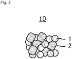
- a cathode mixture 10 shown in Fig. 2 is a cathode mixture used for an all solid-state battery, and a feature thereof is to include a cathode active material 1; and a sulfide solid electrolyte 2, wherein the cathode active material 1 consists of a composite oxide containing Li, Ni, Co, and Mn, the cathode active material 1 has a layered rock-salt crystal phase, and the concentration of cobalt inside the cathode active material 1 is higher than that of a surface of the cathode active material 1.
- the cathode active material 1 consists of a composite oxide containing Li, Ni, Co, and Mn.
- This composite oxide may contain (an) element(s) other than Li, Ni, Co, Mn and O as far as the problem can be solved.
- the composite oxide consists of Li, Ni, Co, Mn, and O.
- the cathode active material 1 has a layered rock-salt crystal phase.
- These diffraction peak positions fluctuate a little according to composition in the cathode active material.
- the values of 2 ⁇ represent the diffraction peak positions in a discharging state (state where Li is not released).
- the cathode active material 1 may include (a) crystal phase(s) other than a layered rock-salt crystal phase as far as the problem can be solved.
- crystal phase(s) other than a layered rock-salt crystal phase Preferably, diffraction peaks only derived from a layered rock-salt crystal phase are confirmed in X-ray diffraction measurement as described above which the cathode active material 1 is subjected to.
- the concentration of cobalt inside the cathode active material 1 is higher than that of the surface of the cathode active material 1.
- the concentration of cobalt may increase either continuously or intermittently from the surface of the cathode active material 1 toward the inside thereof. Increasing the concentration of cobalt inside the cathode active material 1 makes it possible to secure a high capacity as active material. In contrast, lowering the concentration of cobalt of the surface of the cathode active material 1 makes it possible to suppress release of oxygen in charging.
- the composition ratio of Li, Ni, Co, and Mn (and O) in the cathode active material 1 is not specifically limited as long as a layered rock-salt crystal phase is included. As described above, the concentration of cobalt inside the cathode active material 1 is higher than that of its surface. In other words, the surface of the cathode active material 1 has composition different from its inside. Co does not have to exist on the surface of the cathode active material 1. Neither Ni nor Mn has to exist inside the cathode active material 1.
- the inside of the cathode active material 1 preferably has composition represented by LiNi x Co y Mn z O 2 ⁇ (0 ⁇ x ⁇ 0.5, 0 ⁇ y ⁇ 1, 0 ⁇ z ⁇ 0.5, 0.8 ⁇ x + y + z ⁇ 1.2).
- a layered rock-salt type composite oxide is easy to be obtained while the concentration of cobalt is increased.
- the lower limit of x is more preferably no less than 0.25, and the upper limit thereof is more preferably no more than 0.40.
- the lower limit of y is more preferably no less than 0.25, and the upper limit thereof is more preferably no more than 0.40.
- the lower limit of z is more preferably no less than 0.25, and the upper limit thereof is more preferably no more than 0.40. Especially preferably, all of x, y, and z are 1/3.
- the lower limit is more preferably no less than 0.9, and further preferably no less than 0.95, and the upper limit is more preferably no more than 1.1, and further preferably no more than 1.05.
- the molar ratio of O to Li (O/Li) is 2.
- oxygen is excessive, or the layered rock-salt crystal phase is partially deficient in oxygen, compared to the stoichiometric ratio as a layered rock-salt crystal phase, a crystalline structure of the layered rock-salt crystal phase itself is kept, and a desired effect can be exerted.
- the molar ratio of O to Li (O/Li) is preferably 1.6 to 2.2.
- ⁇ is preferably no more than 0.2.
- Specific examples of the composition inside the cathode active material 1 include LiCoO 2 , and LiNi 1/3 Co 1/3 Mn 1/3 O 2 .
- the surface of the cathode active material 1 preferably has composition represented by LiNi ⁇ Co ⁇ Mn ⁇ O 2 ⁇ (0 ⁇ ⁇ ⁇ 0.5, 0 ⁇ ⁇ ⁇ 1, 0 ⁇ ⁇ ⁇ 0.5, 0.8 ⁇ ⁇ + ⁇ + ⁇ ⁇ 1.2, ⁇ ⁇ y).
- the lower limit of ⁇ is more preferably no less than 0.3, and further preferably no less than 0.4.
- the upper limit of ⁇ is more preferably no more than 0.3, and further preferably no more than 0.2.
- ⁇ is smaller than y.
- the lower limit of ⁇ is more preferably no less than 0.3, and further preferably no less than 0.40.
- the lower limit is more preferably no less than 0.9, and further preferably no less than 0.95, and the upper limit is more preferably no more than 1.1, and further preferably no more than 1.05.
- the molar ratio of O to Li (O/Li) is 2.
- a crystalline structure of the layered rock-salt crystal phase itself is kept, and a desired effect can be exerted even if oxygen is excessive, or the layered rock-salt crystal phase is partially deficient in oxygen, compared to the stoichiometric ratio as a layered rock-salt crystal phase.
- the molar ratio of O to Li (O/Li) is preferably 1.6 to 2.2.
- ⁇ is preferably no more than 0.2.
- Specific examples of the composition of the surface of the cathode active material 1 include LiNi 0.4 Co 0.2 Mn 0.4 O 2 , and LiNi 0.5 Mn 0.5 O 2 .
- the rate of increasing a c-axis length of the layered rock-salt crystal phase included inside the cathode active material 1 in charging is higher than that of its surface in charging.
- the rate of increasing a c-axis length of the layered rock-salt crystal phase included inside the cathode active material 1 in charging is preferably no less than 1.012, and that of its surface in charging is preferably lower than 1.012.
- the shape of the cathode active material 1 is not specifically limited, and is preferably in the form of a particle.
- the form may be either a primary particle, or a secondary particle of cohering primary particles.
- too small a particle diameter thereof leads to too large a specific surface area, especially, enlargement of the total area to be coated with a coating layer 3 described later when the coating layer 3 is provided for the surface of the cathode active material 1, and further increase of the volume of the coating layer 3 in the cathode mixture, which is sometimes disadvantageous in view of the process cost, the material cost, and an energy density of a cathode.
- the cathode active material 1 when the cathode active material 1 is in the form of a particle, its mean particle diameter (D 50 ) is preferably 1 ⁇ m to 15 ⁇ m.
- the mean particle diameter (D 50 ) represents a median diameter (50% mean volume particle diameter) derived from particle size distribution measured resulting from a particle counter based on a laser scattering and diffraction method.
- its BET specific surface area is preferably 0.2 m 2 /g to 2.0 m 2 /g.
- the content of the cathode active material 1 in the cathode mixture 10 is not specifically limited, and may be properly determined according to the performance of the battery to be aimed.
- the content of the cathode active material 1 is preferably 30 mass% to 90 mass% if the whole of the cathode mixture 10 (whole of the solid content) is 100 mass%.
- the lower limit is more preferably no less than 50 mass%, and the upper limit is more preferably no more than 85 mass%.
- any sulfide that is used as a solid electrolyte for an all solid-state battery can be employed for the sulfide solid electrolyte 2.
- Examples thereof include Li 2 S-P 2 S 5 , Li 2 S-SiS 2 , LiI-Li 2 S-SiS 2 , LiI-Si 2 S-P 2 S 5 , LiI-LiBr-Li 2 S-P 2 S 5 , LiI-Li 2 S-P 2 S 5 , LiI-Li 2 O-Li 2 S-P 2 S 5 , LiI-Li 2 S-P 2 O 5 , LiI-Li 3 PO 4 -P 2 S 5 , and Li 2 S-P 2 S 5 -GeS 2 .
- a sulfide solid electrolyte containing Li 2 S-P 2 S 5 is more preferable.
- One may be individually used, or two or more may be mixed to be used as the sulfide solid electrolyte 2.
- the shape of the sulfide solid electrolyte 2 is not specifically limited.
- the sulfide solid electrolyte 2 may be in the form of a particle.
- the content of the sulfide solid electrolyte 2 in the cathode mixture 10 is not specifically restricted, and may be properly determined according to the performance of the battery to be aimed.
- the content of the sulfide solid electrolyte 2 is preferably 5 mass% to 65 mass% if the whole of the cathode mixture 10 (whole of the solid content) is 100 mass%.
- the lower limit is more preferably no less than 10 mass%, and the upper limit is more preferably no more than 45 mass%.
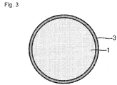
- the cathode mixture 10 further includes the coating layer 3 with which the surface of the cathode active material 1 is coated.
- the coating layer 3 is a layer containing Li and Nb, and is especially preferably a layer formed of lithium niobate.
- the coating layer 3 can function as a protective layer for preventing the cathode active material 1 from being directly in contact with the sulfide solid electrolyte 2. From this viewpoint, all over the surface of the cathode active material 1 is preferably coated with the coating layer 3 as shown in Fig. 3 .
- the thickness of the coating layer 3 is not specifically limited, and for example, may be 5 nm to 50 nm.
- the cathode mixture 10 may contain other constituents in addition to the cathode active material 1, the sulfide solid electrolyte 2, and the coating layer 3 as far as the problem can be solved.
- the cathode mixture 10 preferably contains a conductive additive.
- a conductive additive employed for an all solid-state battery can be employed. Examples thereof include carbon materials such as acetylene black (AB), Ketjenblack (KB), vapor grown carbon fiber (VGCF), carbon nanotubes (CNT), carbon nanofibers (CNF), and graphite; and metallic materials such as nickel, aluminum, and stainless steel. Especially, a carbon material is preferable.
- One may be used individually, or two or more may be mixed to be used as the conductive additive. Any shape such as powder and fiber can be employed for the conductive additive.
- the content of the conductive additive in the cathode mixture 10 is not specifically restricted, and may be properly determined according to the performance of the battery to be aimed.
- the content of the conductive additive is preferably 0.5 mass% to 20 mass% if the whole of the cathode mixture 10 is 100 mass%.
- the lower limit is more preferably no less than 1 mass%, and the upper limit is more preferably no more than 10 mass%.
- the cathode mixture 10 preferably contains a binder. Any known one as a binder employed for an all solid-state battery can be employed. For example, at least one selected from styrene-butadiene rubber (SBR), carboxymethyl cellulose (CMC), acrylonitrile-butadiene rubber (ABR), butadiene rubber (BR), polyvinylidene fluoride (PVDF), polytetrafluoroethylene (PTFE), etc. can be used.
- SBR styrene-butadiene rubber
- CMC carboxymethyl cellulose
- ABR acrylonitrile-butadiene rubber
- BR butadiene rubber
- PVDF polyvinylidene fluoride
- PTFE polytetrafluoroethylene
- the content of the binder is preferably 1 mass% to 30 mass% if the whole of the cathode mixture 10 is 100 mass%.
- the lower limit is more preferably no less than 2 mass%, and the upper limit is more preferably no more than 15 mass%.
- the cathode mixture 10 may contain (a) cathode active material(s) other than the cathode active material 1 as far as the problem can be solved. Examples thereof include a spinel type cathode active material, and an olivine type cathode active material.
- the cathode mixture 10 may contain (a) solid electrolyte(s) other than the sulfide solid electrolyte 2 as far as the problem can be solved.
- solid electrolyte(s) other than the sulfide solid electrolyte 2 as far as the problem can be solved.
- oxide solid electrolytes such as lithium lanthanum zirconate, LiPON, Li 1+X Al X Ge 2-X (PO 4 ) 3 , Li-SiO-based glass, and Li-Al-S-O-based glass.
- the concentration of cobalt inside the cathode active material 1 that consists of the composite oxide containing Li, Ni, Co, and Mn, and that has a layered rock-salt crystal phase is increased to secure a high capacity, and at the same time the concentration of cobalt of its surface is lowered, which makes it possible to suppress release of oxygen in charging. That is, when the cathode mixture 10 of this disclosure is used in a cathode 100 of an all solid-state battery 1000 described later, oxidation of the sulfide solid electrolyte due to release of oxygen from the cathode active material can be suppressed, and increase of the internal resistance of the all solid-state battery 1000 can be suppressed.
- the cathode 100 shown in Fig. 4 is a cathode used for an all solid-state battery, and includes the cathode mixture 10, and a cathode current collector 20.
- the cathode mixture 10 is provided for a surface of the cathode current collector 20 in the form of a layer.
- the thickness of a layer consisting of the cathode mixture 10 is preferably 1 ⁇ m to 1 mm.
- the cathode current collector 20 may have conductivity, and for example, may be constituted of metal foil, a metal mesh, etc. Especially, metal foil is preferable.
- metals that may constitute the cathode current collector 20 include Ni, Cr, Au, Pt, Al, Fe, Ti, Zn, and stainless steel.
- the cathode current collector 20 may have some coating layer over its surface.
- the thickness of the cathode current collector 20 is not specifically limited, and for example, is preferably 0.1 ⁇ m to 1 mm, and is more preferably 1 ⁇ m to 100 ⁇ m.
- the all solid-state battery 1000 shown in Fig. 5 includes the cathode 100, an anode 200, and a solid electrolyte layer 300.
- the structure of the cathode 100 is as described above. Detailed description thereof is omitted here.
- the structure of the anode 200 in the all solid-state battery 1000 is obvious for the person skilled in the art. Hereinafter one example thereof will be described.
- the anode 200 usually includes an anode mixture layer 30 containing an anode active material, and containing, as optional constituents, a solid electrolyte, a binder, a conductive additive, and other additives (thickener etc.).
- the anode mixture layer 30 is preferably provided for a surface of an anode current collector 40.
- the anode mixture layer 30 is a layer containing at least an anode active material, and may further contain a solid electrolyte, a binder, a conductive additive, etc. optionally, in addition to the anode active material.
- a known active material may be used as the anode active material.
- known active materials one whose potential at which a predetermined ion is stored/released (charge/discharge potential) is baser than the cathode active material 1 can be used as the anode active material.
- Si or a Si alloy when a lithium ion battery is configured, Si or a Si alloy; a carbon material such as graphite and hard carbon; any oxide such as lithium titanate; a lithium metal or a lithium alloy; or the like can be used as the anode active material.
- the solid electrolyte, the binder, and the conductive additive may be properly selected among the examples for ones used in the cathode mixture 10, to be used.
- the contents of the constituents in the anode mixture layer 30 may be the same as conventional ones.
- the shape of the anode mixture layer 30 may be the same as a conventional one as well. Specifically, the anode mixture layer 30 in the form of a sheet is preferable from the viewpoint that the all solid-state battery 1000 can be easily configured.
- the thickness of the anode mixture layer 30 is preferably 0.1 ⁇ m to 1 mm, and more preferably 1 ⁇ m to 100 ⁇ m.
- the thickness of the anode mixture layer 30 is preferably determined as such that the capacity of the anode 200 is larger than that of the cathode 100.
- the anode current collector 40 may be constituted of metal foil, a metal mesh, etc. Especially, metal foil is preferable. Examples of metals that may constitute the anode current collector 40 include Cu, Ni, Fe, Ti, Co, Zn, and stainless steel. The anode current collector 40 may have some coating layer over its surface. The thickness of the anode current collector 40 is not specifically limited, and for example, is preferably 0.1 ⁇ m to 1 mm, and is more preferably 1 ⁇ m to 100 ⁇ m.
- the anode 200 having the above described structure can be easily produced via a process such as: kneading the anode active material, and the solid electrolyte, binder, and conductive additive which are to be optionally contained, in solvent, to obtain paste or slurry containing an anode mixture, and thereafter applying the paste or slurry to the surface of the anode current collector, to be dried.
- the anode 200 can be produced via not only such a wet process, but also a dry process.
- the constitution of the solid electrolyte layer 300 in the all solid-state battery 1000 is obvious for the person skilled in the art. Hereinafter one example thereof will be described.
- the solid electrolyte layer 300 contains a sold electrolyte, and optionally a binder.
- a sulfide solid electrolyte as described above is preferably employed for the solid electrolyte.
- an inorganic solid electrolyte other than a sulfide solid electrolyte may be contained in addition to a sulfide solid electrolyte as far as a desired effect can be exerted.
- the same one as a binder as described above can be properly selected to be used.
- the contents of the constituents in the solid electrolyte layer 300 may be the same as conventional ones.
- the shape of the solid electrolyte layer 300 may be the same as a conventional one as well. Specifically, the solid electrolyte layer 300 in the form of a sheet is preferable.
- the solid electrolyte layer 300 in the form of a sheet can be easily produced via a process such as: kneading the solid electrolyte, and optionally the binder in solvent, to obtain a slurry electrolyte composition, and thereafter applying this electrolyte composition to a surface of a base material or to (a) surface(s) of the cathode mixture layer and/or anode mixture layer, to be dried; and press-molding the solid electrolyte in a dry process.
- the thickness of the solid electrolyte layer 300 is preferably 0.1 ⁇ m to 300 ⁇ m, and more preferably 0.1 ⁇ m to 100 ⁇ m.
- the all solid-state battery 1000 may include necessary terminals, a battery case, etc. in addition to the cathode 100, the anode 200, and the solid electrolyte layer 300. These members are publicly known, and detailed description thereof is omitted here.
- the cathode mixture 10 can be produced as the flow shown in Fig. 6 . That is, a method S10 for producing the cathode mixture 10 includes: a coating step S1 of coating a surface of an inside active material 1a with an outside active material 1b, to obtain the cathode active material 1; and a mixing step S2 of mixing the cathode active material 1 and the sulfide solid electrolyte 2, to obtain the cathode mixture 10.
- the cathode active material 1 consists of a composite oxide containing Li, Ni, Co, and Mn.
- the cathode active material 1 has a layered rock-salt crystal phase. It is important in the producing method S10 that the concentration of cobalt in the inside active material 1a is higher than that in the outside active material 1b.
- the surface of the inside active material 1a is coated with the outside active material 1b, to obtain the cathode active material 1.
- Both the inside active material 1a and outside active material 1b preferably consist of a composite oxide having a layered rock-salt crystal phase.
- the composite oxide constituting the inside active material 1a preferably consists of a composite oxide having the same composition as the inside of the cathode active material 1. That is, the inside active material 1a preferably has composition represented by LiNi x Co y Mn z O 2 ⁇ (0 ⁇ x ⁇ 0.5, 0 ⁇ y ⁇ 1, 0 ⁇ z ⁇ 0.5, 0.8 ⁇ x + y + z ⁇ 1.2).
- the composite oxide constituting the outside active material 1b preferably consists of a composite oxide having the same composition as the surface of the cathode active material 1.
- the outside active material 1b preferably has composition represented by LiNi ⁇ Co ⁇ Mn ⁇ O 2 ⁇ (0 ⁇ ⁇ ⁇ 0.5, 0 ⁇ ⁇ ⁇ 1, 0 ⁇ ⁇ ⁇ 0.5, 0.8 ⁇ ⁇ + ⁇ + ⁇ ⁇ 1.2, ⁇ ⁇ y).
- Preferred ranges of x, y, z, ⁇ , ⁇ , ⁇ , and ⁇ in the composition formulae are as described above, and detailed description thereof is omitted here.
- the inside active material 1a can be easily obtained by a method known as a method for obtaining a layered rock-salt type lithium composite oxide.
- the inside active material 1a can be easily obtained by, for example, mixing every raw material (a Li compound, a Ni compound, a Co compound, and a Mn compound) so that the materials have the composition ratio as described above, and calcining the mixed materials in a proper atmosphere such as an atmospheric atmosphere at a temperature of no less than a temperature at which a layered rock-salt crystal phase deposits.
- a proper atmosphere such as an atmospheric atmosphere at a temperature of no less than a temperature at which a layered rock-salt crystal phase deposits.
- commercially available one may be used as the inside active material 1a.
- the inside active material 1a is preferably in the form of a particle.
- a method for coating the surface of the inside active material 1 a with the outside active material 1b is not specifically limited.
- the surface of the inside active material 1a can be coated with the outside active material 1b by, for example, coating the surface of the inside active material 1a with raw materials of the outside active material 1b (a Li compound, a Ni compound, a Co compound, and a Mn compound.
- a Li compound, a Ni compound, a Co compound, and a Mn compound a Li compound, a Ni compound, a Co compound, and a Mn compound.
- a proper atmosphere such as an atmospheric atmosphere at a temperature of no less than a temperature at which a layered rock-salt crystal phase deposits, to form the outside active material 1b over the surface of the inside active material 1a.
- solution that dissolves the raw materials of the outside active material 1b is preferably touched to the surface of the inside active material 1a.
- the inside active material 1a is preferably immersed in solution that dissolves the raw materials of the outside active material 1b.
- the thickness of a layer of the outside active material 1b is not specifically limited.
- a layer consisting of the outside active material 1b having a thickness of 10 nm to 200 nm is provided for the surface of the inside active material 1a.
- the thickness of the layer consisting of the outside active material 1b is more preferably 50 nm to 150 nm. No interface is necessary to exist between the inside active material 1a and the outside active material 1b.
- the cathode active material 1 obtained in the coating step S1 does not necessarily have a core-shell structure including the inside active material 1a as a core and the outside active material 1b as a shell, and an intermediate region may be provided between the inside active material 1a and the outside active material 1b.
- the inside active material 1a when the inside active material 1a is immersed in solution that dissolves the raw materials of the outside active material 1b, thereafter to be calcined to coat the surface of the inside active material 1a with the outside active material 1b, there is a case where transition metals diffuse across the interface between the inside active material 1a and the outside active material 1b, to form an intermediate region having composition that is in the middle of the composition of the inside active material 1a and that of the outside active material 1b.
- the rate of increasing a c-axis length of the layered rock-salt crystal phase in charging lowers, and release of oxygen is suppressed.
- the concentration of cobalt is high, capacity as active material can be improved.
- the rate of increasing a c-axis length of the layered rock-salt crystal phase included in the inside active material 1a in charging is higher than that included in the outside active material 1b in charging.
- coating the surface of the cathode active material 1 with the coating layer 3 makes it possible to suppress formation of a high resistance layer on the interface between the cathode active material 1 and the sulfide solid electrolyte 2. That is, in the coating step S1, preferably, the surface of the inside active material 1a is coated with the outside active material 1b to obtain the cathode active material 1, and the surface of the cathode active material 1 is further coated with the coating layer 3 containing Li and Nb (more preferably, a layer formed of lithium niobate).
- a way itself of coating the surface of the cathode active material 1 with the coating layer 3 is publicly known ( JP 2017-059393 A , JP 2015-056307 A , etc.).
- a precursor solution containing niobium and lithium is sprayed and atomized, to be dried and heat-treated, which makes it possible to coat the surface of the cathode active material 1 with the coating layer 3.
- a precursor solution containing niobium and lithium is sprayed and atomized, to be dried and heat-treated, which makes it possible to coat the surface of the cathode active material 1 with the coating layer 3.
- the cathode active material 1 and the sulfide solid electrolyte 2 are mixed to obtain the cathode mixture 10.
- other constituents such as the conductive additive and the binder may be further mixed in addition to the cathode active material 1 and the sulfide solid electrolyte 2.
- a way of mixing the cathode active material 1 and the sulfide solid electrolyte 2 to obtain the cathode mixture 10 is not specifically limited.
- the mixing step S2 can be carried out using a known mixing means. Mixing in the mixing step S2 may be either wet mixing using solvent, or dry mixing not using solvent (mixing of granular materials each other).
- the cathode active material 1 and the sulfide solid electrolyte 2 are mixed together with solvent, to obtain paste or slurry containing the cathode mixture 10.
- a solvent used in this case is not specifically limited.
- the cathode 100 of this disclosure can be produced as follows: that is, a method for producing the cathode 100 includes: a step of producing the cathode mixture 10 by the producing method S10; and a step of layering the cathode mixture 10 onto the surface of the cathode current collector 20.
- the cathode 100 can be easily produced via a process such as applying paste or slurry containing the cathode mixture 10 to the surface of the cathode current collector 20, to be dried.
- the cathode 100 can be produced by not only such a wet process, but also a dry process.
- the all solid-state battery 1000 of this disclosure can be produced as follows: that is, a method for producing the all solid-state battery 1000 includes: a step of producing the cathode 100 by the producing method described above; and a step of layering the cathode 100, the solid electrolyte layer 300, and the anode 200.
- the all solid-state battery 1000 can be produced by, for example, layering the cathode 100, the solid electrolyte layer 300, and the anode 200 as described above, to obtain a laminate, and upon attaching proper terminals etc., sealing up the laminate in a battery case.
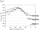
- NCM111 means layered rock-salt type LiNi 1/3 Co 1/3 Mn 1/3 O 2
- NCM424" means layered rock-salt type LiNi 0.4 Co 0.2 Mn 0.4 O 2
- NCM505" means layered rock-salt type LiNi 0.5 Mn 0.5 O 2 .
- the deposit generated in the reaction solution was cleaned and dried, to obtain a precursor of an inside active material.
- concentrations of nickel sulfate, cobalt sulfate, and manganese sulfate in the mixed aqueous solution were changed to obtain precursors having various compositions.
- each of the concentrations of nickel sulfate, cobalt sulfate, and manganese sulfate in the mixed aqueous solution was 0.5 mol/L
- each of the concentrations of nickel sulfate and manganese sulfate was 0.6 mol/L, and that of cobalt sulfate was 0.3 mol/L
- each of the concentrations of nickel sulfate and manganese sulfate was 0.7 mol/L, and that of cobalt sulfate was 0 mol/L.
- Powder of the obtained precursor and powder of Li 2 CO 3 were mixed, and heat-treated in an air atmosphere at 700 to 1000°C, to obtain inside active material.
- the numbers of moles of Ni, Co, and Mn contained in the precursor and that of Li included in Li 2 CO 3 were adjusted to have a proper quantity ratio as a layered rock-salt type composite oxide.
- the obtained slurry was moved into a rotary evaporator, and was subjected to evaporation to dryness under a reduced pressure while being stirred as the temperature was kept 50°C, to coat the surface of the inside active material with a precursor of the outside active material.
- the grounded powder was heated at 480°C in an air atmosphere for 3 hours. Thereafter, the resultant was mixed with lithium hydroxide, and calcined at 850°C in an air atmosphere for 2 hours, to coat the surface of the inside active material with the outside active material, to obtain a cathode active material.
- the number of moles of lithium hydroxide was equal to that of the transition metals contained in the precursor of the outside active material.
- the surface of the obtained cathode active material was sputtered with lithium niobate (LiNbO 3 ) by a barrel sputtering method, to be coated.
- the powder of the active material was stirred in a reactor during sputtering so that the surface of the cathode active material was uniformly coated with lithium niobate.
- the cathode active material Li 2 S-P 2 S 5 -based glass ceramic
- a conductive additive VGCF manufactured by Showa Denko K.K.
- anode active material graphite powder
- a sulfide solid electrolyte (same as the above) were put and fully mixed, to be pasty.
- the obtained paste was dripped onto a laboratory dish, to be dried to obtain powder of an anode mixture.
- Powder of NCM111, powder of NCM424, and powder of NCM505 were made conforming to the procedures for making the inside active material, and the ratios of increasing c-axis lengths in charging were measured by the following procedures:
- the made all solid-state battery was subjected to charge/discharge testing under the following conditions:
- the made all solid-state battery was subjected to resistance evaluation testing under the following conditions:
- the made all solid-state battery was subjected to aging testing under the following conditions:
- Table 1 and Fig. 7 show the relations between the amount of extracting Li of layered rock-salt type LiNi x Co 1-2x Mn x O 2 and a c-axis length of a layered rock-salt crystal phase.
- Table 1 Ni [mol%] Co [mol%] Mn [mol%] C-axis length in uncharging [ ⁇ ] C-axis length in charging (max.) [ ⁇ ] Rate of increasing c-axis length [-] NCM111 33 33 33 14.1990 14.4342 1.017 NCM424 40 20 40 14.3060 14.4710 1.012 NCM505 50 0 50 14.4023 14.5082 1.007
- Table 2 shows "compositions of inside active material and outside active material which were used when cathode active material was made", “presence or not of coating layer”, “rate of increasing c-axis length of layered rock-salt crystal phase of inside active material”, and “rate of increasing c-axis length of layered rock-salt crystal phase of outside active material” as to the all solid-state battery according to each of Examples and Comparative Examples.
- Table 2 Composition of inside active material Composition of outside active material Coating layer Rate of increasing c-axis length of inside active material Rate of increasing c-axis length of outside active material
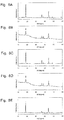
- Figs. 8A to 8E The cathode active materials used in Examples 1 and 2 and Comparative Examples 1 to 3 were subjected to measurement by means of X-ray diffraction before coated with the coating layers. The results are shown in Figs. 8A to 8E.
- Fig. 8A corresponds to Example 1
- Fig. 8B corresponds to Example 2
- Fig. 8C corresponds to Comparative Example 1
- Fig. 8D corresponds to Comparative Example 2
- Fig. 8E corresponds to Comparative Example 3.
- diffraction peaks only derived from a layered rock-salt crystal phase were confirmed, and no different phase was confirmed, as to all the cathode active materials. It is believed that the surfaces of the layered rock-salt type inside active materials were able to be coated with the layered rock-salt type outside active materials in both Examples 1 and 2.
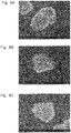
- Figs. 9A to 9C The states of the surfaces of the cathode active materials according to Examples 1 and 2 and Comparative Example 1 were observed by means of SEM. The results are shown in Figs. 9A to 9C. Fig. 9A corresponds to Example 1, Fig. 9B corresponds to Example 2, and Fig. 9C corresponds to Comparative Example 1. As is apparent from the results shown in Figs. 9A to 9C , coating the surface of the inside active material with the outside active material changed the state of the surface of the active material.
- Table 3 shows "capacity measured by charge/discharge testing", “initial resistance value measured by resistance evaluation testing”, “resistance value after aging testing”, and “rate of increasing resistance after aging testing compared with resistance before aging testing” as to the all solid-state battery of each of Examples and Comparative Examples.
- "capacity measured by charge/discharge testing” and “initial resistance value measured by resistance evaluation testing” are relatively represented on the basis of Comparative Example 1 (100).
- Table 3 Capacity (relative value) Initial resistance value (relative value) Increased resistance value Rate of increasing resistance value Ex. 1 99 78 133 171% Ex. 2 100 72 128 178% Comp. Ex. 1 100 100 100 189 189% Comp. Ex. 2 101 138 219 159% Comp. Ex. 3 43 550 660 120%
- Comparative Examples 2 and 3 since the cathode active materials were formed of only composite oxides having low concentrations of cobalt, release of oxygen in charging was suppressed, and the rates of increasing the resistance values were lower than those of Examples 1 and 2 and Comparative Example 1. However, since in Comparative Examples 2 and 3, the initial resistance values were high first of all, there was no advantage over Comparative Example 1. Specifically, in Comparative Example 3, not only the initial resistance value was high, but also the capacity was lowered. The reason why the initial resistances were high in Comparative Examples 2 and 3 is believed to be because lithium ion conductivity in particles lowered accompanying lowering of the concentrations of cobalt.
- Example 3 and Comparative Example 4 were examples where the surfaces of the cathode active materials were not coated with the coating layers (layers of lithium niobate). As is apparent from the comparison between Example 3 and Comparative Example 4, the effect of having lowered the concentration of cobalt of the surface of the cathode active material more than that inside the cathode active material was confirmed as well when the layer of lithium niobate was not included. Since there was no difference between Example 3 and Comparative Example 4 in theoretical capacity, it is believed that difference in capacity in this case was due to difference in initial resistance. That is, the resistance in Example 3 can be said to have been lower.
- the all solid-state battery using the cathode mixture of this disclosure can be used in a wide range of power sources such as a small-sized power source for portable terminals and an onboard large-sized power source.
Landscapes
- Chemical & Material Sciences (AREA)
- Electrochemistry (AREA)
- General Chemical & Material Sciences (AREA)
- Chemical Kinetics & Catalysis (AREA)
- Engineering & Computer Science (AREA)
- Manufacturing & Machinery (AREA)
- Inorganic Chemistry (AREA)
- Composite Materials (AREA)
- Materials Engineering (AREA)
- Physics & Mathematics (AREA)
- Condensed Matter Physics & Semiconductors (AREA)
- General Physics & Mathematics (AREA)
- Battery Electrode And Active Subsutance (AREA)
- Secondary Cells (AREA)
Applications Claiming Priority (1)
| Application Number | Priority Date | Filing Date | Title |
|---|---|---|---|
| JP2018005891A JP6988502B2 (ja) | 2018-01-17 | 2018-01-17 | 全固体電池用正極合剤、全固体電池用正極、全固体電池及びこれらの製造方法 |
Publications (3)
| Publication Number | Publication Date |
|---|---|
| EP3514865A1 true EP3514865A1 (de) | 2019-07-24 |
| EP3514865B1 EP3514865B1 (de) | 2025-05-07 |
| EP3514865B8 EP3514865B8 (de) | 2025-06-11 |
Family
ID=64426737
Family Applications (1)
| Application Number | Title | Priority Date | Filing Date |
|---|---|---|---|
| EP18207504.4A Active EP3514865B8 (de) | 2018-01-17 | 2018-11-21 | Kathodenmischung für festkörperbatterie, kathode für festkörperbatterie, festkörperbatterie und verfahren zu deren herstellung |
Country Status (7)
| Country | Link |
|---|---|
| US (1) | US11569502B2 (de) |
| EP (1) | EP3514865B8 (de) |
| JP (1) | JP6988502B2 (de) |
| KR (1) | KR102165779B1 (de) |
| CN (1) | CN110048084A (de) |
| BR (1) | BR102019000425A2 (de) |
| RU (1) | RU2693858C1 (de) |
Cited By (2)
| Publication number | Priority date | Publication date | Assignee | Title |
|---|---|---|---|---|
| EP3883021A1 (de) * | 2020-03-18 | 2021-09-22 | Samsung SDI Co., Ltd. | Kathode für eine festkörpersekundärbatterie und festkörpersekundärbatterie damit |
| EP4131507A4 (de) * | 2021-04-12 | 2025-07-09 | Shenzhen Dynanonic Innovazone New Energy Tech Co Ltd | Lithiumzusatzadditiv, herstellungsverfahren dafür und anwendung davon |
Families Citing this family (12)
| Publication number | Priority date | Publication date | Assignee | Title |
|---|---|---|---|---|
| JP6633161B1 (ja) * | 2018-09-14 | 2020-01-22 | Jx金属株式会社 | 正極活物質、及び、その製造方法、並びに、正極、及びリチウムイオン電池 |
| DE102018222129A1 (de) * | 2018-12-18 | 2020-06-18 | Fraunhofer-Gesellschaft zur Förderung der angewandten Forschung e.V. | Kathodeneinheit und Verfahren zum Herstellen einer Kathodeneinheit |
| JP7078682B2 (ja) | 2019-09-18 | 2022-05-31 | 財團法人工業技術研究院 | 高速充電リチウムイオン電池 |
| JP7226302B2 (ja) * | 2019-12-26 | 2023-02-21 | トヨタ自動車株式会社 | 固体電池及びその製造方法 |
| CN111434618B (zh) * | 2020-01-17 | 2022-07-22 | 蜂巢能源科技有限公司 | 无钴层状正极材料及制备方法、锂离子电池 |
| JP7778682B2 (ja) * | 2020-03-24 | 2025-12-02 | 三井金属株式会社 | 活物質、該活物質を含む電極合剤及び電池 |
| JP2023518984A (ja) | 2020-03-27 | 2023-05-09 | ボード オブ リージェンツ,ザ ユニバーシティ オブ テキサス システム | リチウム電池のための低コバルト及びコバルトを含まない高エネルギー正極材料 |
| CN111785974B (zh) * | 2020-08-25 | 2022-03-08 | 中南大学 | 用于硫化物固态锂离子电池的正极包覆方法、正极及电池 |
| JP7455045B2 (ja) * | 2020-10-22 | 2024-03-25 | 本田技研工業株式会社 | 正極活物質 |
| JPWO2022270186A1 (de) * | 2021-06-24 | 2022-12-29 | ||
| KR102885303B1 (ko) * | 2022-12-16 | 2025-11-12 | 포스코홀딩스 주식회사 | 전고체 전지용 양극 활물질, 이의 제조방법 및 이를 포함하는 전고체 전지 |
| KR102872623B1 (ko) * | 2022-12-16 | 2025-10-20 | 포스코홀딩스 주식회사 | 전고체 전지용 양극 활물질, 이의 제조방법 및 이를 포함하는 전고체 전지 |
Citations (8)
| Publication number | Priority date | Publication date | Assignee | Title |
|---|---|---|---|---|
| JP2009193780A (ja) * | 2008-02-13 | 2009-08-27 | Sony Corp | 正極活物質、これを用いた正極および非水電解質二次電池 |
| JP2010073539A (ja) * | 2008-09-19 | 2010-04-02 | Toyota Motor Corp | 電極体及びその製造方法、並びに、リチウムイオン二次電池 |
| JP2014040363A (ja) | 2012-07-24 | 2014-03-06 | Tanaka Chemical Corp | 複合酸化物、複合遷移金属化合物、複合酸化物の製造方法、非水電解質二次電池用の正極活物質、並びに非水電解質二次電池 |
| JP2015056307A (ja) | 2013-09-12 | 2015-03-23 | トヨタ自動車株式会社 | 活物質複合粉体及びリチウム電池並びにその製造方法 |
| US20160315324A1 (en) * | 2015-04-27 | 2016-10-27 | Toyota Jidosha Kabushiki Kaisha | Active material composite particle, electrode active material layer, and all solid lithium battery |
| WO2017013520A1 (en) * | 2015-07-22 | 2017-01-26 | Umicore | Cathode material for rechargeable solid state lithium ion battery |
| JP2017059393A (ja) | 2015-09-16 | 2017-03-23 | 株式会社東芝 | 非水電解質電池及び電池パック |
| JP2017103065A (ja) | 2015-11-30 | 2017-06-08 | トヨタ自動車株式会社 | 全固体電池システム |
Family Cites Families (20)
| Publication number | Priority date | Publication date | Assignee | Title |
|---|---|---|---|---|
| JP5036100B2 (ja) * | 2001-03-30 | 2012-09-26 | 三洋電機株式会社 | 非水電解質二次電池およびその製造方法 |
| NZ520452A (en) | 2002-10-31 | 2005-03-24 | Lg Chemical Ltd | Anion containing mixed hydroxide and lithium transition metal oxide with gradient of metal composition |
| CN1312792C (zh) * | 2003-03-14 | 2007-04-25 | 清美化学股份有限公司 | 锂二次电池用正极活性物质粉末 |
| KR100533095B1 (ko) * | 2003-04-09 | 2005-12-01 | 주식회사 엘지화학 | 과방전 방지제를 포함하는 양극 활물질 및 이를 이용한리튬 이차 전지 |
| JP4062169B2 (ja) * | 2003-05-20 | 2008-03-19 | 株式会社日立製作所 | リチウム二次電池用正極材料 |
| PL1716609T3 (pl) * | 2003-12-31 | 2019-02-28 | Lg Chem, Ltd. | Sproszkowany materiał aktywny elektrody o kompozycji zależnej od wielkości i sposób jego przygotowania |
| JP4984436B2 (ja) * | 2005-05-27 | 2012-07-25 | ソニー株式会社 | リチウムイオン二次電池用正極活物質およびその製造方法、並びにリチウムイオン二次電池用正極およびリチウムイオン二次電池 |
| KR100927244B1 (ko) * | 2007-10-13 | 2009-11-16 | 주식회사 엘지화학 | 리튬 이차전지용 양극 활물질 |
| KR101185366B1 (ko) * | 2010-01-14 | 2012-09-24 | 주식회사 에코프로 | 회분식 반응기(batch reactor)를 사용하여 농도구배층을 가지는 리튬 이차 전지용 양극활물질 전구체 및 양극활물질을 제조하는 방법 |
| KR101452029B1 (ko) * | 2011-09-20 | 2014-10-23 | 주식회사 엘지화학 | 고용량 양극활물질 및 이를 포함하는 리튬이차전지 |
| CN102368548B (zh) * | 2011-10-31 | 2012-11-28 | 上海中兴派能能源科技有限公司 | 改性三元材料、其前驱体及该材料和前驱体的制备方法 |
| US9711797B2 (en) * | 2012-05-07 | 2017-07-18 | Seeo, Inc. | Coated particles for lithium battery cathodes |
| JP6092567B2 (ja) | 2012-05-31 | 2017-03-08 | トヨタ自動車株式会社 | 硫化物系固体電池用正極用スラリー、硫化物系固体電池用正極及びその製造方法、並びに、硫化物系固体電池及びその製造方法 |
| JP2014049310A (ja) * | 2012-08-31 | 2014-03-17 | Toyota Motor Corp | 活物質材料、全固体電池、および活物質材料の製造方法 |
| KR101744091B1 (ko) * | 2012-09-04 | 2017-06-07 | 삼성에스디아이 주식회사 | 리튬 이차 전지용 양극 활물질, 이의 제조 방법 및 이를 포함하는 리튬 이차 전지 |
| JP5967287B2 (ja) * | 2013-02-28 | 2016-08-10 | 日産自動車株式会社 | 正極活物質、正極材料、正極および非水電解質二次電池 |
| RU2553460C2 (ru) * | 2013-11-13 | 2015-06-20 | Федеральное государственное бюджетное образовательное учреждение высшего образования "Московский государственный университет имени М.В. Ломоносова" (МГУ) | Катодные материалы для твердооксидных топливных элементов на основе никельсодержащих слоистых перовскитоподобных оксидов |
| CN104022280B (zh) | 2014-06-27 | 2017-04-12 | 南通瑞翔新材料有限公司 | 一种高电压锂离子正极材料及其制备方法 |
| EP3373369A4 (de) * | 2015-11-05 | 2019-06-12 | Sumitomo Chemical Company, Limited | Positivelektrodenaktivmaterial für lithiumsekundärbatterien, verfahren zur herstellung eines positivelektrodenaktivmaterials für lithiumsekundärbatterien, positivelektrode für lithiumsekundärbatterien und lithiumsekundärbatterie |
| CN106784798B (zh) | 2017-02-15 | 2020-01-14 | 中国科学院过程工程研究所 | 正极活性材料、制备方法及包含其的高性能正极浆料和全固态锂离子电池 |
-
2018
- 2018-01-17 JP JP2018005891A patent/JP6988502B2/ja active Active
- 2018-11-19 US US16/195,279 patent/US11569502B2/en active Active
- 2018-11-21 EP EP18207504.4A patent/EP3514865B8/de active Active
- 2018-11-27 CN CN201811424377.4A patent/CN110048084A/zh active Pending
- 2018-12-07 KR KR1020180157384A patent/KR102165779B1/ko active Active
-
2019
- 2019-01-09 BR BR102019000425-8A patent/BR102019000425A2/pt not_active Application Discontinuation
- 2019-01-09 RU RU2019100027A patent/RU2693858C1/ru active
Patent Citations (8)
| Publication number | Priority date | Publication date | Assignee | Title |
|---|---|---|---|---|
| JP2009193780A (ja) * | 2008-02-13 | 2009-08-27 | Sony Corp | 正極活物質、これを用いた正極および非水電解質二次電池 |
| JP2010073539A (ja) * | 2008-09-19 | 2010-04-02 | Toyota Motor Corp | 電極体及びその製造方法、並びに、リチウムイオン二次電池 |
| JP2014040363A (ja) | 2012-07-24 | 2014-03-06 | Tanaka Chemical Corp | 複合酸化物、複合遷移金属化合物、複合酸化物の製造方法、非水電解質二次電池用の正極活物質、並びに非水電解質二次電池 |
| JP2015056307A (ja) | 2013-09-12 | 2015-03-23 | トヨタ自動車株式会社 | 活物質複合粉体及びリチウム電池並びにその製造方法 |
| US20160315324A1 (en) * | 2015-04-27 | 2016-10-27 | Toyota Jidosha Kabushiki Kaisha | Active material composite particle, electrode active material layer, and all solid lithium battery |
| WO2017013520A1 (en) * | 2015-07-22 | 2017-01-26 | Umicore | Cathode material for rechargeable solid state lithium ion battery |
| JP2017059393A (ja) | 2015-09-16 | 2017-03-23 | 株式会社東芝 | 非水電解質電池及び電池パック |
| JP2017103065A (ja) | 2015-11-30 | 2017-06-08 | トヨタ自動車株式会社 | 全固体電池システム |
Cited By (2)
| Publication number | Priority date | Publication date | Assignee | Title |
|---|---|---|---|---|
| EP3883021A1 (de) * | 2020-03-18 | 2021-09-22 | Samsung SDI Co., Ltd. | Kathode für eine festkörpersekundärbatterie und festkörpersekundärbatterie damit |
| EP4131507A4 (de) * | 2021-04-12 | 2025-07-09 | Shenzhen Dynanonic Innovazone New Energy Tech Co Ltd | Lithiumzusatzadditiv, herstellungsverfahren dafür und anwendung davon |
Also Published As
| Publication number | Publication date |
|---|---|
| US20190221843A1 (en) | 2019-07-18 |
| JP6988502B2 (ja) | 2022-01-05 |
| EP3514865B8 (de) | 2025-06-11 |
| BR102019000425A2 (pt) | 2019-07-30 |
| US11569502B2 (en) | 2023-01-31 |
| JP2019125510A (ja) | 2019-07-25 |
| CN110048084A (zh) | 2019-07-23 |
| KR20190087948A (ko) | 2019-07-25 |
| EP3514865B1 (de) | 2025-05-07 |
| KR102165779B1 (ko) | 2020-10-14 |
| RU2693858C1 (ru) | 2019-07-05 |
Similar Documents
| Publication | Publication Date | Title |
|---|---|---|
| EP3514865B1 (de) | Kathodenmischung für festkörperbatterie, kathode für festkörperbatterie, festkörperbatterie und verfahren zu deren herstellung | |
| EP3082183B1 (de) | Positivelektrodenaktivmaterialpulver, positivelektroden mit positivelektrodenaktivmaterialpulver und sekundärbatterie | |
| EP3242351B1 (de) | Kathodenaktivmaterial für lithium-ionen-sekundärbatterie, verfahren zur herstellung davon und lithium-ionen-sekundärbatterie damit | |
| JP6848181B2 (ja) | 非水系電解質二次電池用正極活物質とその製造方法、及び非水系電解質二次電池 | |
| EP3272710A1 (de) | Nickelbasiertes aktivmaterial für lithiumsekundärbatterie, verfahren zur herstellung davon und lithiumsekundärbatterie mit positivelektrode mit dem nickelbasierten aktivmaterial | |
| EP3333129A1 (de) | Nickelbasiertes aktivmaterial für lithiumsekundärbatterie, herstellungsverfahren dafür und lithiumsekundärbatterie mit positivelektrode damit | |
| JP6978182B2 (ja) | 非水系電解質二次電池用正極活物質とその製造方法、および該正極活物質を用いた非水系電解質二次電池 | |
| EP3550643A1 (de) | Nickelaktivmaterialvorläufer für lithiumsekundärbatterie, verfahren zur herstellung eines nickelaktivmaterialvorläufers, durch das verfahren hergestellter nickelaktivmaterialvorläufer für lithiumsekundärbatterie sowie lithiumsekundärbatterie mit kathode mit nickelaktivmaterial | |
| KR20130139711A (ko) | 양극 활물질, 그 제조방법, 및 이를 포함하는 리튬 전지 | |
| JP7131056B2 (ja) | 非水系電解液二次電池用正極活物質、非水系電解液二次電池 | |
| JP2019139862A (ja) | リチウムイオン電池用正極活物質、リチウムイオン電池用正極活物質の製造方法、リチウムイオン電池用正極及びリチウムイオン電池 | |
| EP3718973A1 (de) | Lithiumhaltiges übergangsmetallkomplexoxid, positivelektrodenaktivmaterial für lithiumsekundärzelle, positivelektrode für lithiumsekundärzelle, lithiumsekundärzelle und verfahren zur herstellung von lithiumhaltigem übergangsmetallkomplexoxid | |
| JP7087349B2 (ja) | リチウムイオン二次電池用正極活物質、リチウムイオン二次電池及びリチウムイオン二次電池用正極活物質の製造方法 | |
| EP3757067A1 (de) | Metallverbundhydroxidpartikel und verfahren zur herstellung davon, positivelektrodenaktivsubstanz für sekundärbatterien mit wasserfreiem elektrolyt, verfahren zur herstellung davon und sekundärbatterie mit wasserfreiem elektrolyt | |
| JP2021005475A (ja) | リチウムイオン二次電池用正極活物質およびその製造方法、並びに、リチウムイオン二次電池 | |
| CN117352736A (zh) | 一种具有复合包覆层的钴基正极材料及其制备方法和锂离子电池 | |
| KR20200101853A (ko) | 비수전해질 2차 전지용 정극 활물질 및 그 제조방법 | |
| CN105098170A (zh) | 活性物质前驱体、其制备方法和由其形成的活性物质 | |
| EP2884567B1 (de) | Verfahren zur herstellung eines vorläufers eines metallbeschichteten elektrodenaktivmaterials | |
| JP2021005548A (ja) | リチウムイオン二次電池用正極活物質およびその製造方法、並びに、リチウムイオン二次電池 | |
| WO2019163847A1 (ja) | 金属複合水酸化物とその製造方法、非水電解質二次電池用正極活物質とその製造方法、および非水電解質二次電池 | |
| EP3771000B1 (de) | Positives elektrodenaktivmaterial für sekundärbatterien mit wasserfreiem elektrolyt und verfahren zur herstellung davon | |
| EP4597626A1 (de) | Positivelektrodenmaterial für lithium-ionen-sekundärbatterie und verfahren zur herstellung davon, positivelektrode für lithium-ionen-sekundärbatterie und lithium-ionen-sekundärbatterie | |
| JP7455244B2 (ja) | 活物質及びその製造方法 | |
| EP4589686A1 (de) | Kathodenaktivmaterial, kathode für lithiumsekundärbatterie und lithiumsekundärbatterie |
Legal Events
| Date | Code | Title | Description |
|---|---|---|---|
| PUAI | Public reference made under article 153(3) epc to a published international application that has entered the european phase |
Free format text: ORIGINAL CODE: 0009012 |
|
| STAA | Information on the status of an ep patent application or granted ep patent |
Free format text: STATUS: REQUEST FOR EXAMINATION WAS MADE |
|
| 17P | Request for examination filed |
Effective date: 20181121 |
|
| AK | Designated contracting states |
Kind code of ref document: A1 Designated state(s): AL AT BE BG CH CY CZ DE DK EE ES FI FR GB GR HR HU IE IS IT LI LT LU LV MC MK MT NL NO PL PT RO RS SE SI SK SM TR |
|
| AX | Request for extension of the european patent |
Extension state: BA ME |
|
| STAA | Information on the status of an ep patent application or granted ep patent |
Free format text: STATUS: EXAMINATION IS IN PROGRESS |
|
| 17Q | First examination report despatched |
Effective date: 20210510 |
|
| GRAP | Despatch of communication of intention to grant a patent |
Free format text: ORIGINAL CODE: EPIDOSNIGR1 |
|
| STAA | Information on the status of an ep patent application or granted ep patent |
Free format text: STATUS: GRANT OF PATENT IS INTENDED |
|
| RIC1 | Information provided on ipc code assigned before grant |
Ipc: H01M 4/02 20060101ALN20241126BHEP Ipc: H01M 4/62 20060101ALI20241126BHEP Ipc: H01M 4/505 20100101ALI20241126BHEP Ipc: H01M 4/04 20060101ALI20241126BHEP Ipc: H01M 4/1391 20100101ALI20241126BHEP Ipc: H01M 10/42 20060101ALI20241126BHEP Ipc: H01M 10/0562 20100101ALI20241126BHEP Ipc: H01M 10/052 20100101ALI20241126BHEP Ipc: H01M 4/525 20100101ALI20241126BHEP Ipc: H01M 4/36 20060101AFI20241126BHEP |
|
| INTG | Intention to grant announced |
Effective date: 20241219 |
|
| GRAS | Grant fee paid |
Free format text: ORIGINAL CODE: EPIDOSNIGR3 |
|
| GRAA | (expected) grant |
Free format text: ORIGINAL CODE: 0009210 |
|
| STAA | Information on the status of an ep patent application or granted ep patent |
Free format text: STATUS: THE PATENT HAS BEEN GRANTED |
|
| AK | Designated contracting states |
Kind code of ref document: B1 Designated state(s): AL AT BE BG CH CY CZ DE DK EE ES FI FR GB GR HR HU IE IS IT LI LT LU LV MC MK MT NL NO PL PT RO RS SE SI SK SM TR |
|
| REG | Reference to a national code |
Ref country code: GB Ref legal event code: FG4D |
|
| REG | Reference to a national code |
Ref country code: CH Ref legal event code: PK Free format text: BERICHTIGUNG B8 Ref country code: CH Ref legal event code: EP |
|
| RAP4 | Party data changed (patent owner data changed or rights of a patent transferred) |
Owner name: TOYOTA JIDOSHA KABUSHIKI KAISHA |
|
| RIN2 | Information on inventor provided after grant (corrected) |
Inventor name: YOSHIDA, JUN Inventor name: KOSAKA, DAICHI |
|
| REG | Reference to a national code |
Ref country code: DE Ref legal event code: R096 Ref document number: 602018081686 Country of ref document: DE |
|
| REG | Reference to a national code |
Ref country code: IE Ref legal event code: FG4D |
|
| REG | Reference to a national code |
Ref country code: NL Ref legal event code: MP Effective date: 20250507 |
|
| REG | Reference to a national code |
Ref country code: DE Ref legal event code: R084 Ref document number: 602018081686 Country of ref document: DE |
|
| PG25 | Lapsed in a contracting state [announced via postgrant information from national office to epo] |
Ref country code: PT Free format text: LAPSE BECAUSE OF FAILURE TO SUBMIT A TRANSLATION OF THE DESCRIPTION OR TO PAY THE FEE WITHIN THE PRESCRIBED TIME-LIMIT Effective date: 20250908 Ref country code: FI Free format text: LAPSE BECAUSE OF FAILURE TO SUBMIT A TRANSLATION OF THE DESCRIPTION OR TO PAY THE FEE WITHIN THE PRESCRIBED TIME-LIMIT Effective date: 20250507 Ref country code: ES Free format text: LAPSE BECAUSE OF FAILURE TO SUBMIT A TRANSLATION OF THE DESCRIPTION OR TO PAY THE FEE WITHIN THE PRESCRIBED TIME-LIMIT Effective date: 20250507 |
|
| REG | Reference to a national code |
Ref country code: LT Ref legal event code: MG9D |
|
| PG25 | Lapsed in a contracting state [announced via postgrant information from national office to epo] |
Ref country code: NO Free format text: LAPSE BECAUSE OF FAILURE TO SUBMIT A TRANSLATION OF THE DESCRIPTION OR TO PAY THE FEE WITHIN THE PRESCRIBED TIME-LIMIT Effective date: 20250807 Ref country code: GR Free format text: LAPSE BECAUSE OF FAILURE TO SUBMIT A TRANSLATION OF THE DESCRIPTION OR TO PAY THE FEE WITHIN THE PRESCRIBED TIME-LIMIT Effective date: 20250808 |
|
| PG25 | Lapsed in a contracting state [announced via postgrant information from national office to epo] |
Ref country code: NL Free format text: LAPSE BECAUSE OF FAILURE TO SUBMIT A TRANSLATION OF THE DESCRIPTION OR TO PAY THE FEE WITHIN THE PRESCRIBED TIME-LIMIT Effective date: 20250507 Ref country code: PL Free format text: LAPSE BECAUSE OF FAILURE TO SUBMIT A TRANSLATION OF THE DESCRIPTION OR TO PAY THE FEE WITHIN THE PRESCRIBED TIME-LIMIT Effective date: 20250507 |
|
| REG | Reference to a national code |
Ref country code: AT Ref legal event code: MK05 Ref document number: 1793498 Country of ref document: AT Kind code of ref document: T Effective date: 20250507 |
|
| PG25 | Lapsed in a contracting state [announced via postgrant information from national office to epo] |
Ref country code: BG Free format text: LAPSE BECAUSE OF FAILURE TO SUBMIT A TRANSLATION OF THE DESCRIPTION OR TO PAY THE FEE WITHIN THE PRESCRIBED TIME-LIMIT Effective date: 20250507 |
|
| PG25 | Lapsed in a contracting state [announced via postgrant information from national office to epo] |
Ref country code: HR Free format text: LAPSE BECAUSE OF FAILURE TO SUBMIT A TRANSLATION OF THE DESCRIPTION OR TO PAY THE FEE WITHIN THE PRESCRIBED TIME-LIMIT Effective date: 20250507 |
|
| PG25 | Lapsed in a contracting state [announced via postgrant information from national office to epo] |
Ref country code: AT Free format text: LAPSE BECAUSE OF FAILURE TO SUBMIT A TRANSLATION OF THE DESCRIPTION OR TO PAY THE FEE WITHIN THE PRESCRIBED TIME-LIMIT Effective date: 20250507 |
|
| PGFP | Annual fee paid to national office [announced via postgrant information from national office to epo] |
Ref country code: FR Payment date: 20250930 Year of fee payment: 8 |
|
| PG25 | Lapsed in a contracting state [announced via postgrant information from national office to epo] |
Ref country code: RS Free format text: LAPSE BECAUSE OF FAILURE TO SUBMIT A TRANSLATION OF THE DESCRIPTION OR TO PAY THE FEE WITHIN THE PRESCRIBED TIME-LIMIT Effective date: 20250807 |
|
| PG25 | Lapsed in a contracting state [announced via postgrant information from national office to epo] |
Ref country code: IS Free format text: LAPSE BECAUSE OF FAILURE TO SUBMIT A TRANSLATION OF THE DESCRIPTION OR TO PAY THE FEE WITHIN THE PRESCRIBED TIME-LIMIT Effective date: 20250907 |
|
| PG25 | Lapsed in a contracting state [announced via postgrant information from national office to epo] |
Ref country code: LV Free format text: LAPSE BECAUSE OF FAILURE TO SUBMIT A TRANSLATION OF THE DESCRIPTION OR TO PAY THE FEE WITHIN THE PRESCRIBED TIME-LIMIT Effective date: 20250507 |