EP3499115B1 - Phare de véhicule - Google Patents
Phare de véhicule Download PDFInfo
- Publication number
- EP3499115B1 EP3499115B1 EP18186735.9A EP18186735A EP3499115B1 EP 3499115 B1 EP3499115 B1 EP 3499115B1 EP 18186735 A EP18186735 A EP 18186735A EP 3499115 B1 EP3499115 B1 EP 3499115B1
- Authority
- EP
- European Patent Office
- Prior art keywords
- micro
- incident
- lens
- exit
- light
- Prior art date
- Legal status (The legal status is an assumption and is not a legal conclusion. Google has not performed a legal analysis and makes no representation as to the accuracy of the status listed.)
- Active
Links
- 230000003287 optical effect Effects 0.000 claims description 33
- 230000005540 biological transmission Effects 0.000 claims description 23
- 230000000694 effects Effects 0.000 description 5
- 230000006870 function Effects 0.000 description 4
- 238000005286 illumination Methods 0.000 description 4
- 238000000034 method Methods 0.000 description 3
- 239000000463 material Substances 0.000 description 2
- 239000004065 semiconductor Substances 0.000 description 2
- 230000009131 signaling function Effects 0.000 description 2
- 238000003491 array Methods 0.000 description 1
- 239000011248 coating agent Substances 0.000 description 1
- 238000000576 coating method Methods 0.000 description 1
- 230000008021 deposition Effects 0.000 description 1
- 238000010586 diagram Methods 0.000 description 1
- 238000005516 engineering process Methods 0.000 description 1
- 238000009434 installation Methods 0.000 description 1
- 239000003550 marker Substances 0.000 description 1
- 238000012986 modification Methods 0.000 description 1
- 230000004048 modification Effects 0.000 description 1
- 230000001105 regulatory effect Effects 0.000 description 1
- 230000011664 signaling Effects 0.000 description 1
Images


Classifications
-
- F—MECHANICAL ENGINEERING; LIGHTING; HEATING; WEAPONS; BLASTING
- F21—LIGHTING
- F21S—NON-PORTABLE LIGHTING DEVICES; SYSTEMS THEREOF; VEHICLE LIGHTING DEVICES SPECIALLY ADAPTED FOR VEHICLE EXTERIORS
- F21S41/00—Illuminating devices specially adapted for vehicle exteriors, e.g. headlamps
- F21S41/20—Illuminating devices specially adapted for vehicle exteriors, e.g. headlamps characterised by refractors, transparent cover plates, light guides or filters
- F21S41/285—Refractors, transparent cover plates, light guides or filters not provided in groups F21S41/24-F21S41/28
-
- F—MECHANICAL ENGINEERING; LIGHTING; HEATING; WEAPONS; BLASTING
- F21—LIGHTING
- F21S—NON-PORTABLE LIGHTING DEVICES; SYSTEMS THEREOF; VEHICLE LIGHTING DEVICES SPECIALLY ADAPTED FOR VEHICLE EXTERIORS
- F21S41/00—Illuminating devices specially adapted for vehicle exteriors, e.g. headlamps
- F21S41/10—Illuminating devices specially adapted for vehicle exteriors, e.g. headlamps characterised by the light source
- F21S41/14—Illuminating devices specially adapted for vehicle exteriors, e.g. headlamps characterised by the light source characterised by the type of light source
- F21S41/141—Light emitting diodes [LED]
- F21S41/143—Light emitting diodes [LED] the main emission direction of the LED being parallel to the optical axis of the illuminating device
-
- F—MECHANICAL ENGINEERING; LIGHTING; HEATING; WEAPONS; BLASTING
- F21—LIGHTING
- F21S—NON-PORTABLE LIGHTING DEVICES; SYSTEMS THEREOF; VEHICLE LIGHTING DEVICES SPECIALLY ADAPTED FOR VEHICLE EXTERIORS
- F21S41/00—Illuminating devices specially adapted for vehicle exteriors, e.g. headlamps
- F21S41/20—Illuminating devices specially adapted for vehicle exteriors, e.g. headlamps characterised by refractors, transparent cover plates, light guides or filters
- F21S41/25—Projection lenses
- F21S41/265—Composite lenses; Lenses with a patch-like shape
-
- F—MECHANICAL ENGINEERING; LIGHTING; HEATING; WEAPONS; BLASTING
- F21—LIGHTING
- F21S—NON-PORTABLE LIGHTING DEVICES; SYSTEMS THEREOF; VEHICLE LIGHTING DEVICES SPECIALLY ADAPTED FOR VEHICLE EXTERIORS
- F21S41/00—Illuminating devices specially adapted for vehicle exteriors, e.g. headlamps
- F21S41/40—Illuminating devices specially adapted for vehicle exteriors, e.g. headlamps characterised by screens, non-reflecting members, light-shielding members or fixed shades
-
- F—MECHANICAL ENGINEERING; LIGHTING; HEATING; WEAPONS; BLASTING
- F21—LIGHTING
- F21V—FUNCTIONAL FEATURES OR DETAILS OF LIGHTING DEVICES OR SYSTEMS THEREOF; STRUCTURAL COMBINATIONS OF LIGHTING DEVICES WITH OTHER ARTICLES, NOT OTHERWISE PROVIDED FOR
- F21V19/00—Fastening of light sources or lamp holders
-
- F—MECHANICAL ENGINEERING; LIGHTING; HEATING; WEAPONS; BLASTING
- F21—LIGHTING
- F21V—FUNCTIONAL FEATURES OR DETAILS OF LIGHTING DEVICES OR SYSTEMS THEREOF; STRUCTURAL COMBINATIONS OF LIGHTING DEVICES WITH OTHER ARTICLES, NOT OTHERWISE PROVIDED FOR
- F21V5/00—Refractors for light sources
-
- F—MECHANICAL ENGINEERING; LIGHTING; HEATING; WEAPONS; BLASTING
- F21—LIGHTING
- F21V—FUNCTIONAL FEATURES OR DETAILS OF LIGHTING DEVICES OR SYSTEMS THEREOF; STRUCTURAL COMBINATIONS OF LIGHTING DEVICES WITH OTHER ARTICLES, NOT OTHERWISE PROVIDED FOR
- F21V5/00—Refractors for light sources
- F21V5/04—Refractors for light sources of lens shape
-
- G—PHYSICS
- G02—OPTICS
- G02B—OPTICAL ELEMENTS, SYSTEMS OR APPARATUS
- G02B27/00—Optical systems or apparatus not provided for by any of the groups G02B1/00 - G02B26/00, G02B30/00
- G02B27/30—Collimators
-
- G—PHYSICS
- G02—OPTICS
- G02B—OPTICAL ELEMENTS, SYSTEMS OR APPARATUS
- G02B3/00—Simple or compound lenses
- G02B3/02—Simple or compound lenses with non-spherical faces
- G02B3/08—Simple or compound lenses with non-spherical faces with discontinuous faces, e.g. Fresnel lens
-
- F—MECHANICAL ENGINEERING; LIGHTING; HEATING; WEAPONS; BLASTING
- F21—LIGHTING
- F21S—NON-PORTABLE LIGHTING DEVICES; SYSTEMS THEREOF; VEHICLE LIGHTING DEVICES SPECIALLY ADAPTED FOR VEHICLE EXTERIORS
- F21S41/00—Illuminating devices specially adapted for vehicle exteriors, e.g. headlamps
- F21S41/40—Illuminating devices specially adapted for vehicle exteriors, e.g. headlamps characterised by screens, non-reflecting members, light-shielding members or fixed shades
- F21S41/43—Illuminating devices specially adapted for vehicle exteriors, e.g. headlamps characterised by screens, non-reflecting members, light-shielding members or fixed shades characterised by the shape thereof
-
- F—MECHANICAL ENGINEERING; LIGHTING; HEATING; WEAPONS; BLASTING
- F21—LIGHTING
- F21W—INDEXING SCHEME ASSOCIATED WITH SUBCLASSES F21K, F21L, F21S and F21V, RELATING TO USES OR APPLICATIONS OF LIGHTING DEVICES OR SYSTEMS
- F21W2102/00—Exterior vehicle lighting devices for illuminating purposes
- F21W2102/10—Arrangement or contour of the emitted light
-
- F—MECHANICAL ENGINEERING; LIGHTING; HEATING; WEAPONS; BLASTING
- F21—LIGHTING
- F21W—INDEXING SCHEME ASSOCIATED WITH SUBCLASSES F21K, F21L, F21S and F21V, RELATING TO USES OR APPLICATIONS OF LIGHTING DEVICES OR SYSTEMS
- F21W2107/00—Use or application of lighting devices on or in particular types of vehicles
- F21W2107/10—Use or application of lighting devices on or in particular types of vehicles for land vehicles
Definitions
- the present invention relates to a lamp for a vehicle, and more particularly, a lamp for a vehicle, which is capable of forming a beam pattern which is configured as a micro optical system and satisfies light distribution performance requirements.
- a vehicle includes a variety of types of lamps having an illumination function for recognizing an object disposed proximate to the vehicle during low light conditions (e.g., night) and a signaling function for informing other vehicles or road users proximate to the vehicle of a driving state of the vehicle.
- low light conditions e.g., night
- signaling function for informing other vehicles or road users proximate to the vehicle of a driving state of the vehicle.
- a headlamp, a fog lamp, and the like generally have the illumination function.
- a turn signaling lamp, a tail lamp, a brake lamp, a side marker lamp, and the like generally have the signaling function.
- installation criteria and specifications for the lamps for a vehicle are regulated by law so that each lamp can adequately perform its function.
- a headlamp which forms a low beam pattern or a high beam pattern to ensure a front field of vision for a driver during nighttime driving, performs an important function for driving safety.
- DE 10 2005 013950 A1 is directed to an arrangement for the homogeneous illumination of an image plane, comprising illumination optics having an array of emitters with a broad emitting characteristic, for example, an arrangement of luminescent diodes (LEDs, OLEDs), an integrator array, and an image-generating element, and the optical axis of an emitter is associated with the mechanical axis of an integrator of the integrator array.
- At least two microlens arrays are provided for the purpose of achieving an angular homogeneity of the rays exiting from the integrator array on the illuminated area of the image-generating element at the light outlet of the integrator array.
- WO 2017/066818 relates to a micro-projection light module for a motor vehicle headlight, comprising at least one light source and at least one projection device which projects the light emitted by the at least one light source into an area in front of the motor vehicle in the form of at least one light distribution.
- the projection device comprises an input lens system consisting of one, two or more micro-input lenses that are preferably arranged in an array, and an output lens system consisting of one, two or more micro-output lenses that are preferably arranged in an array, wherein to every micro-input lens exactly one micro-output lens is assigned, wherein the micro-input lenses are designed in such a way and/or the micro-input lenses and the micro-output lenses are assigned to each other in such a way that substantially all of the light exiting from a micro-input lens strikes exclusively the micro-output lens assigned to it, and wherein the light bent by the micro-input lenses is projected by the micro-output lenses in an area in front of the motor vehicle in the form of at least one lightdistribution, a first aperture device being disposed between the input lens system and the output lens system, and at least one second aperture device being arranged between the input lens system and the output lens system.
- aspects of the present invention provide a lamp for a vehicle capable of forming a beam pattern, which satisfies the requirements for the light distribution performance, by adjusting combinations and arrangements of micro incident/exit units which form an incident/exit area.
- a lamp for a vehicle may include a light source portion, a first lens portion with a plurality of micro incident lenses onto which light generated by the light source portion is incident, and a second lens portion with a plurality of micro exit lenses disposed in front of the plurality of micro incident lenses.
- the lamp may form a beam pattern using a combination of one or more micro incident/exit units.
- each of the micro incident/exit units may include one cylinder lens which extends in a first direction and a plurality of corresponding lenses corresponding to the one cylinder lens, and any one of the micro incident lens and the micro exit lens may be the cylinder lens and the other may be the corresponding lens.
- the plurality of corresponding lenses may be arranged in the direction in which the cylinder extends.
- the cylinder lens is the micro incident lens
- light which exits from the cylinder lens may be incident onto the corresponding lens.
- the cylinder lens is the micro exit lens
- light which exits from the corresponding lens may exit toward the cylinder lens.
- Light which exits from the lamp may form a beam pattern which is widened in the first direction and/or a beam pattern which is narrowed in a second direction perpendicular to the first direction.
- an incident surface thereof includes, according to the invention, a refraction portion which is bent at both ends of the first direction.
- the light which is incident onto the refraction portion may be narrowed in the first direction.
- the micro incident/exit units of a same configuration in which the one cylinder lens is combined with the same number of the corresponding lenses, may be arranged adjacently.
- the lamp may include first micro incident/exit units in which the one cylinder lens is combined with the two corresponding lenses.
- the first micro incident/exit units may be arranged in an optical axis area to increase a brightness of a high illuminance area of the beam pattern.
- the micro incident/exit units in which the one cylinder lens is combined with the three or more corresponding lenses, may be arranged outside an optical axis area and may form a spread area of the beam pattern.
- the one cylinder lens may be combined with N number of the corresponding lenses.
- the micro incident/exit units may include a first micro incident/exit unit whose N number is 2, a second micro incident/exit unit whose N number is 3, and a third micro incident/exit unit whose N number is 4.
- the first micro incident/exit units may be arranged in an optical axis area to increase a brightness of a high illuminance area of the beam pattern.
- the second micro incident/exit units may be symmetrically arranged in a second direction perpendicular to the first direction with respect to an optical axis to form a part of a spread area of the beam pattern.
- the third micro incident/exit units may be symmetrically arranged in the first direction with respect to an optical axis to form a part of a spread area of the beam pattern.
- the plurality of micro incident lenses may be formed on a surface of a first transmission portion transmitting light, which faces the light source portion.
- the plurality of micro exit lenses may be formed on a surface of a second light transmission portion transmitting light, from which light exits.
- the first light transmission portion and the second light transmission portion may be disposed to abut each other.
- the lamp may further include a shielding portion with a plurality of shields disposed on rear focal points of the plurality of micro exit lenses to obstruct a portion of light which is incident onto the plurality of micro exit lenses.
- the plurality of shields may be disposed on and fixed to a surface of the second light transmission portion which faces the first light transmission portion.
- the first light transmission portion may have a thickness corresponding to a focal distance of the micro incident lens
- the second light transmission portion may have a thickness corresponding to a focal distance of the micro exit lens
- the light source portion may include a light source and a light guide portion configured to guide the light generated by the light source to the first lens portion by adjusting an optical path of the light to be parallel to an optical axis of the light source.
- the light guide portion may be one of a Fresnel lens and a collimator lens.
- At least two of the micro incident/exit units may have different numbers of the plurality of corresponding lenses that correspond to the one cylinder lens.
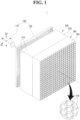
- FIGS. 1 and 2 are perspective views of the lamp 1 according to some exemplary embodiments of the present invention.
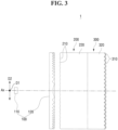
- FIG. 3 is a side view of the lamp 1 according to some exemplary embodiments of the present invention
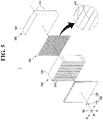
- FIGS. 4 and 5 are exploded perspective views of the lamp 1 according to some exemplary embodiments of the present invention.
- the lamp 1 may include a light source portion 100, a first lens portion 200, a second lens portion 300, and a shielding portion 400.
- the lamp 1 may be a headlamp for ensuring a front field of vision in a vehicle when the vehicle is traveling during low light conditions (e.g., night) by emitting light in a driving direction or through a dark place such as a tunnel and the like, but is not limited thereto.
- the lamp 1 may be used not only as a headlamp, but also as any of a variety of lamps installed in a vehicle such as a tail lamp, a brake lamp, a fog lamp, a position lamp, a turn-signal lamp, a daytime running lamp, a backup lamp, and the like.
- the exemplary embodiments of the present invention will be described regarding the lamp 1 as a headlamp that forms a low beam pattern having a certain cut-off line CL to prevent a driver of a vehicle in front or a vehicle approaching in an opposite lane from being blinded, but it is merely an example for aiding in understanding the present invention.
- the present invention is not limited thereto, and a variety of beam patterns may be formed according to use of the lamp 1 according to some exemplary embodiments of the present invention.
- Components included in the lamp 1 according to some exemplary embodiments of the present invention may be added, deleted, or changed based on each of the beam patterns.
- the light source portion 100 may include a light source 110 and a light guide portion 120.
- a semiconductor light emitting diode such as an LED lamp may be used as the light source 110.
- the light source 110 is not limited thereto, and a variety of types of light sources such as a bulb and the like may be used as the light source 110 in addition to the semiconductor LED.
- the light guide portion 120 may guide light generated by the light source 110 at a certain light irradiation angle, to the first lens portion 200 by adjusting an optical path of the light to be parallel to an optical axis Ax of the light source 110.
- the optical axis Ax of the light source 110 may represent a line which passes a center of a light emitting surface of the light source 110 perpendicularly.
- the light guide portion 120 may reduce the light loss by allowing the light generated by the light source 110 to be incident onto the first lens portion 200 as much as possible and allow the light which is incident onto the first lens portion 200 to be uniformly incident onto the first lens portion 200 overall by adjusting the optical path of the light to be parallel to the optical axis Ax of the light source 110.
- a Fresnel lens configured as a lens having a shape of plural rings may be used as the light guide portion 120 to reduce a thickness thereof and to adjust the optical path of the light generated by the light source 110 to be parallel to the optical axis Ax of the light source 110.
- the present invention is not limited thereto, and a variety of types of lenses such as a collimator lens and the like capable of adjusting the optical path of the light generated by the light source 110 may be used as the light guide portion 120.
- the first lens portion 200 may include a plurality of micro incident lenses 210 onto which the light generated by the light source portion 100 is incident. Incident surfaces of the plurality of micro incident lenses 210 may collectively form an incident surface of the first lens portion 200, and exit surfaces of the plurality of micro incident lenses 210 may collectively form an exit surface of the first lens portion 200.
- the plurality of micro incident lenses 210 may be formed on a surface of a first light transmission portion 220 that is made of a light transmission material, which faces the light source portion 100.
- the first light transmission portion 220 is intended to form the first lens portion 200 and the second lens portion 300 as a single body and may be omitted when the first lens portion 200 and the second lens portion 300 are formed separately.
- the second lens portion 300 may include a plurality of micro exit lenses 310. Incident surfaces of the plurality of micro exit lenses 310 may collectively form an incident surface of the second lens portion 300, and exit surfaces of the plurality of micro exit lenses 310 may collectively form an exit surface of the second lens portion 300.
- the plurality of micro exit lenses 310 may be formed on a surface of a second light transmission portion 320 that is made of a light transmission material from which light exits.
- the second light transmission portion 320 may be omitted for similar reasons as described above in regards to the first lens portion 200.
- the lamp 1 may include a combination of one or more micro incident/exit units and may form a beam pattern.
- each of the micro incident/exit units may include one semicylinder lens (hereinafter, referred to as "a cylinder lens”) and a plurality of corresponding lenses.
- the micro incident/exit unit may include one cylinder lens and a plurality of corresponding lenses.
- any one of the micro incident lens 210 and the micro exit lens 310 may be the cylinder lens and the other may be the corresponding lens.
- the cylinder lens and the plurality of corresponding lenses which form one micro incident/exit unit
- the light which exits from the cylinder lens may be incident onto the micro exit lens 310 which is the corresponding lens.
- the cylinder lens is the micro exit lens 310
- the light may exit toward the cylinder lens from the corresponding lens, which is the micro incident lens 210.
- the cylinder lens may have a semicircular cross section and may extend in length in one direction to have an overall shape obtained by cutting a cylinder in half along a longitudinal direction.
- the cylinder lens may include one or a plurality of arranged lens having a semicylindrical shape which extends in one direction, and a focal line which connects focal points F may be formed along the direction in which the length of the cylinder lens extends.
- a curved surface of the cylinder lens may be a spherical surface or an aspherical surface such as a parabolic surface or a hyperboloid which deviates from a spherical surface.
- a first direction D1 in which the cylinder lens extends lengthwise may be a horizontal direction which is parallel to a line H-H on a screen toward which a beam pattern is emitted
- a second direction D2 may be a vertical direction perpendicular to the optical axis Ax and the first direction D1.
- the first direction D1 and the second direction D2 may be varied depending on the directions in which the lamp 1 is disposed and the cylinder lens extends.
- each of the plurality of micro incident lenses 210 may be the cylinder lens having a semicylindrical shape which extends lengthwise in the first direction D1, and the plurality of micro incident lenses 210 may be arranged in the second direction D2 which is perpendicular to the first direction D1.
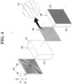
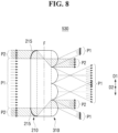
- FIGS. 6 to 8 are views illustrating first to third micro incident/exit units 510, 520, and 530 and light-proceeding paths with respect to the first direction D1 according to some exemplary embodiments of the present invention.
- each of the plurality of micro incident lenses 210 may be the cylinder lens having a semicylindrical shape which extends in the first direction D1, and one or more micro exit lenses 310 corresponding to the one cylinder lens may be arranged in the first direction D1 in which the cylinder lens extends.
- the micro incident/exit unit may include N number of corresponding lenses arranged in the first direction D1 per one cylinder lens.
- the micro incident lenses 210 or the micro exit lenses 310 may be combined, with N being a natural number.
- the first micro incident/exit unit 510 may include one cylinder lens combined with two micro exit lenses 310
- the second micro incident/exit unit 520 may include one cylinder lens combined with three micro exit lenses 310
- the third micro incident/exit unit 530 may include one cylinder lens combined with four micro exit lenses 310.
- the light that is generated by the light source portion 100 and is incident onto and exits from the cylinder lens may be incident onto one or more micro exit lenses 310 combined with the cylinder lens.
- a portion of the light which is incident onto or exits from the micro exit lens 310 may form a beam pattern which is widened in the first direction D1 in which the cylinder lens extends.
- the first beam pattern P1 which is incident from the light guide portion 120 in parallel may be refracted from an exit surface of each of the micro exit lenses 310 toward a front focal point of each of the micro exit lenses 310 and subsequently widened in the first direction D 1.
- the front may be a direction in which light is emitted by the lamp 1 according to some exemplary embodiments of the present invention and may vary based on a position or a direction in which the lamp 1 according to some exemplary embodiments of the present disclosure is installed.
- a beam pattern in which the light which is incident onto the cylinder lens may be widened to be parallel to the line H-H of a low beam pattern LP such that it has an effect of reducing costs of configuring the micro incident lens 210 and the micro exit lens 310, which may be arranged to be parallel to the line H-H, in comparison to a case of including general micro incident lenses.
- an incident surface of the cylinder lens may include a refraction portion 215 which refracts a path of incident light, which is incident to be parallel to the optical axis Ax, in the first direction D1.
- the refraction portion 215 is, according to the invention, bent at the incident surface of the cylinder lens toward both ends of the first direction D1 to be formed as an aspherical surface.
- the second beam pattern P2 which is incident from the light guide portion 120 in parallel may have a path refracted toward a rear focal point F of the micro exit lens 310 opposite the refraction portion 215 in the first direction D1.
- the second beam pattern P2 which is refracted and proceeds, may exit from the exit surface of the micro exit lens 310 in parallel and may be narrowed more in the first direction D1 than an original incident area of the cylinder lens.
- the refraction portion 215 of the cylinder lens may be formed to allow the second beam pattern P2 which is incident in parallel onto the refraction portion 215 to have a focal point F and a curvature with a path refracted in the first direction D1 toward the rear focal point F of the micro exit lens 310.
- any configuration may be applied in which a front focal point F of the micro incident lens 210 and the rear focal point F of the micro exit lens 310 according to some exemplary embodiments of the present invention may be formed in positions corresponding to each other, and the second beam pattern P2 may form a beam pattern which is narrowed in the first direction D1 through the refraction portion 215.
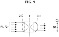
- FIG. 9 is a view illustrating light-proceeding paths of the micro incident/exit unit with respect to the second direction D2 according to some exemplary embodiments of the present invention.
- the micro incident lens 210 may be the cylinder lens which extends in the first direction D1 such that a semicircular-shaped cross section is formed in the second direction D2.
- the first and second beam patterns P1 and P2 which are incident onto in parallel the optical axis Ax from the light guide portion 120, may be refracted and proceed in the second direction D2 toward a front focal point F of the cylinder lens on the incident surface of the cylinder lens and may exit to be parallel from the exit surface of the micro exit lens 310.
- focal distances of the cylinder lens and the micro exit lens 310 or curvatures of the cylinder lens and the micro exit lens 310 with respect to the second direction D2 may be formed to be the same.
- the first and second beam patterns P1 and P2 may form a beam pattern which is narrowed in the second direction D2.
- the lamp 1, may form a beam pattern which is widened in the first direction D1 and narrowed in the second direction D2 through a combination of the first to third micro incident/exit units 510, 520, and 530.
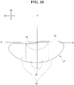
- FIG. 10 is a view illustrating an example of a low beam pattern LP having a cut-off line CL in which left and right top ends have different heights with respect to a line V-V.
- the low beam pattern LP formed by a headlamp it may be necessary to form a beam pattern in which an overall shape of the beam pattern for providing a driver with an adequate field of vision is widened to be parallel to the line H-H which horizontally passes a front focal point of the headlamp.
- relatively high brightness may be necessary to provide a driver with distant visibility for safe driving during nighttime driving.
- relatively low brightness may be necessary to provide a wide visibility angle (e.g., range) with respect to a short distance.
- the lamp 1 may include the combination of the first to third micro incident/exit units with respect to the incident/exit area such that an optimal low beam pattern LP which satisfies light distribution performance requirements in consideration of light distribution properties of the above-described low beam pattern LP is formed.
- each of the first to third micro incident/exit units 510, 520, and 530 may include a combination of one cylinder lens, which extends in the first direction parallel to the line H-H, and the plurality of micro exit lenses 310 arranged in the direction in which the cylinder lens extends.
- the lamp 1 may form the beam pattern which satisfies the light distribution performance requirements by adjusting the combination and arrangement of the first to third micro incident/exit units 510, 520, and 530, which form the incident/exit area.
- the light distribution performance of the formed beam pattern may include brightness (e.g., illuminance, luminance, or luminous intensity, etc.), beam width, light efficiency, and the like of a particular region of the beam pattern.
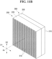
- FIG. 11A is a view illustrating the combination and arrangement of the first to third micro incident/exit units 510, 520, and 530, which form the incident/exit area of the lamp 1 according to some exemplary embodiments of the present invention, viewed from a direction in which the micro incident lenses 210 are formed.
- the lamp 1 may form an optimal low beam pattern LP when the micro incident/exit units 510 are arranged in an optical axis area, the second micro incident/exit units 520 are symmetrically arranged in the second direction D2 with respect to the optical axis Ax, and the third micro incident/exit units 530 are symmetrically arranged in the first direction D1 with respect to the optical axis Ax.
- the first direction D1 of the first to third micro incident/exit units 510, 520, and 530 may be disposed to be parallel to the line H-H, the beam pattern which is widened to be parallel to the horizontal line H-H such as the low beam pattern LP shown in FIG. 10 may be formed.
- the first micro incident/exit units 510 which form a beam pattern with relatively high brightness and a narrow beam width, may be arranged in the optical axis area.
- the second and third micro incident/exit units 520 and 530 which have relatively low brightness and form a beam pattern with a wide beam width may be combined and arranged.
- a first spread area A2 may be formed to have a relatively narrow beam width than that of the beam pattern of a second spread area A3
- the second micro incident/exit units 520 which form a beam pattern with a relatively narrow beam width may be arranged in the first spread area A2 and the third micro incident/exit units 530 which form a relatively wider beam width may be arranged in the second spread area A3.
- the beam pattern having a more condensed and higher brightness may be formed in the high illuminance area A1 and an optimal low beam pattern LP which is diffused with a relatively wider beam width and lower brightness may be formed in the spread areas A2 and A3.
- FIGS. 11A to 11D are views illustrating configurations in which only the first to third micro incident/exit units 510, 520, and 530 are arranged in the incident/exit area of the lamp 1 according to some exemplary embodiments of the present invention, viewed from the direction in which the micro incident lenses 210 are formed.
- the incident/exit area of the lamp 1 may be configured using exclusively the first micro incident/exit units 510, the second micro incident/exit units 520, or the third micro incident/exit units 530.
- FIGS. 11B to 11D are merely examples, and the combination and arrangement of the micro incident/exit units which form the incident/exit area of the lamp 1 according to some exemplary embodiments of the present invention are not limited thereto.
- each of the plurality of micro exit lenses 310 may be a semicylindrical cylinder lens which extends lengthwise in the first direction D1 and the plurality of micro exit lenses 310 may be arranged in the second direction D2 perpendicular to the first direction D1.
- the plurality of micro incident lenses 210 arranged in the first direction D1 may be combined with the cylinder lenses which extend in length in the first direction D1 corresponding thereto as the micro exit lenses 310.
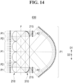
- FIGS. 12 to 14 are views illustrating first to third micro incident/exit units 610, 620, and 630 and light-proceeding paths with respect to the first direction D1 according to other exemplary embodiments which do not form part of the present invention.
- the first micro incident/exit unit 610 may include two micro incident lenses 210 combined with one cylinder lens
- the second micro incident/exit unit 620 may include three micro incident lenses 210 combined with one cylinder lens
- the third micro incident/exit unit 630 may include four micro incident lenses 210 combined with one cylinder lens, in which the cylinder lenses may perform as the micro exit lenses 310.
- the light which is generated by the light source portion 100 and is incident onto and exits from the plurality of micro incident lenses 210 may be incident onto the one cylinder lens combined as the micro exit lens 310 with the plurality of micro incident lenses 210.
- the light which is incident onto and exits from the cylinder lens may form a beam pattern which is widened in the first direction D1 and may form a beam pattern which is narrowed in the second direction D2.
- the first beam pattern P1 which is incident from the light guide portion 120 in parallel may be refracted from an incident surface of each of the micro incident lenses 210 toward a front focal point of each of the micro incident lenses 210, may exit from an exit surface of the cylinder lens which is the micro exit lens 310, and may be subsequently widened in the first direction D1.
- the cylinder lens as the micro exit lens 310, may include the refraction portion 215 which is bent toward both ends of the first direction D1 and formed as an aspherical surface at the exit surface of the cylinder lens.
- the refraction portion 215 may refract a path of a second beam pattern P2 which is a portion of light which is incident from the micro incident lens 210 from the exit surface of the cylinder lens toward the first direction D1 such that the second beam pattern P2 may be refracted and proceed to exit to be parallel to the optical axis Ax.
- the light which is incident onto and exits from the cylinder lens may form the beam pattern which is narrowed in the second direction D2.
- the micro exit lens 310 may be the cylinder lens which extends in the first direction D1
- a semicircular cross section may be formed in the second direction D2 and the first and second beam patterns P1 and P2 which are incident from the micro incident lens 210 through the front focal point F thereof may form a beam pattern which is narrowed at the exit surface of the cylinder lens in the second direction D2.
- Focal distances of the micro incident lens 210 and the cylinder lens or curvatures of the micro incident lens 210 and the cylinder lens with respect to the second direction D2 may be equally formed. However, when the focal distance of the micro incident lens 210 is longer than the focal distance of the cylinder lens or the curvature of the cylinder lens is greater than that of the micro incident lens 210, the first and second beam patterns P1 and P2 may form the beam pattern which is narrowed in the second direction D2.
- the lamp 1 may form a beam pattern which is widened in the first direction D1 and narrowed in the second direction D2 by using a combination of the first to third micro incident/exit units 510, 520, and 530.
- a beam pattern which further is narrowed and has high brightness, may be formed in the high illuminance area A1 of FIG. 10 and a low beam pattern LP which is widened with a relatively wider beam width while forming lower brightness may be formed in the spread areas A2 and A3.
- the shielding portion 400 may be disposed between the first lens portion 200 and the second lens portion 300 and obstruct a portion of light which is incident onto the second lens portion 300 from the first lens portion 200 to form a cut-off line CL of the beam pattern.
- the shielding portion 400 may form the cut-off line CL as shown in FIGS. 4 and 5 .
- the shielding portion 400 may include a plurality of shields 410 which are configured to shield a portion of light which is incident onto each of the plurality of micro exit lenses 310.
- a top end of each of the plurality of shields 410 may be proximate to a focal point F on a rear side of each of the plurality of micro exit lenses 310 and obstruct a portion of light which is incident onto each of the plurality of exit lenses 310 such that the cut-off line CL, as described with reference to FIG. 10 , may be formed.
- the plurality of shields 410 may be fixed to and formed on a surface of the second light transmission portion 320, which faces the first lens portion 200, through deposition, coating, or adhesion thereon.
- each of the plurality of micro incident lenses 210 may be the cylinder lens
- some of the plurality of shields 410 which obstruct a portion of light which exits from any one of the plurality of micro incident lenses 210, may be integrally formed as a single body in the direction in which the cylinder lens extends.
- the present invention is not limited thereto, and each of the plurality of shields 410 may be separately formed and disposed.
- the lamp 1 may form the beam pattern which satisfies light distribution performance requirements such as brightness, beam width, and light efficiency of a particular region of the beam pattern by adjusting the combination and arrangement of the first to third micro incident/exit units 510, 520, and 530, which form the incident/exit area.
- a low beam pattern LP which has a shape widened to be parallel overall to the horizontal line H-H, has relatively high brightness in the high illuminance area A1, and has relatively low brightness in the spread areas A2 and A3, may be formed.
- a lamp for a vehicle may provide one or more effects as follows.
- a micro incident lens is a cylinder lens, and a beam pattern, in which the light incident onto the cylinder is widened to be parallel to a line H-H, may be formed such that the costs for configuring micro incident lenses and micro exit lenses arranged to be parallel to a line H-H may be reduced in comparison to configuring general micro lenses.
- the beam pattern may satisfy the requirements for the light distribution performance by adjusting a combination and arrangements of incident/exit units which form an incident/exit area of a lamp for a vehicle.
Claims (12)
- Phare de véhicule, comprenant :une partie de source lumineuse (100) ;une première partie de lentilles (200) comprenant une pluralité de micro-lentilles incidentes (210), sur laquelle une lumière générée par la partie de source lumineuse est incidente ; etune deuxième partie de lentilles (300) comprenant une pluralité de micro-lentilles de sortie (310) disposées devant la pluralité de micro-lentilles incidentes,où ledit phare est configuré de manière à former un motif de faisceau au moyen d'une combinaison d'une ou de plusieurs unités de micro-lentilles incidentes/de sortie (510, 520, 530),où chacune des unités de micro-lentilles incidentes/de sortie (510, 520, 530) comprend une lentille cylindrique s'étendant dans une première direction (D1) et une pluralité de lentilles correspondantes, lesquelles correspondent à la lentille cylindrique,où la micro-lentille incidente (210) est la lentille cylindrique et la micro-lentille de sortie (310) est la lentille correspondante,où la pluralité de lentilles correspondantes sont disposées dans la première direction (D1) où s'étend la lentille cylindrique, etoù la lumière sortant de la micro-lentille incidente (210) est destinée à être incidente sur la pluralité de micro-lentilles de sortie (310) correspondante,caractériséen ce qu'une surface incidente de la lentille cylindrique comprend une partie de réfraction (215) courbée aux deux extrémités de la première direction (D1).
- Phare selon la revendication 1, où ledit phare est configuré de telle manière que la lumière en sortant forme un motif de faisceau s'élargissant dans la première direction (D1).
- Phare selon la revendication 1 ou la revendication 2, où ledit phare est configuré de telle manière que la lumière en sortant forme un motif de faisceau se resserrant dans une deuxième direction (D2) perpendiculaire à la première direction.
- Phare selon l'une des revendications 1 à 3, où la partie de réfraction (215) est configurée de telle manière que la lumière incidente sur celle-ci ou en sortant se resserre dans la première direction (D1).
- Phare selon l'une des revendications précédentes, où au moins deux unités de micro-lentilles incidentes/de sortie (510, 520, 530) de configuration identique sont disposées adjacentes l'une à l'autre, la lentille cylindrique étant agencée en combinaison avec un nombre identique de lentilles correspondantes.
- Phare selon l'une des revendications précédentes, où les unités de micro-lentilles incidentes/de sortie comprennent un premier groupe (510) d'unités de micro-lentilles incidentes/de sortie dont la lentille cylindrique est agencée en combinaison avec deux lentilles correspondantes, ledit premier groupe (510) étant disposé dans une région d'axe optique de manière à accroître la luminosité d'une zone d'éclairage intense du motif de faisceau.
- Phare selon l'une des revendications précédentes, où les unités de micro-lentilles incidentes/de sortie comprennent un deuxième groupe (520, 530) d'unités de micro-lentilles incidentes/de sortie dont la lentille cylindrique est agencée en combinaison avec au moins trois lentilles correspondantes, ledit deuxième groupe (520, 530) étant disposé en dehors d'une région d'axe optique et destiné à former une zone de diffusion du motif de faisceau.
- Phare selon l'une des revendications précédentes, où, dans la première partie de lentilles (200), la pluralité de micro-lentilles incidentes (210) est formée sur une surface d'une première partie de transmission lumineuse (220) transmettant la lumière et faisant face à la partie de source lumineuse (100),où, dans la deuxième partie de lentilles (300), la pluralité de micro-lentilles de sortie (310) est formée sur une surface d'une deuxième partie de transmission lumineuse (320) transmettant la lumière et dont sort la lumière, etoù la première partie de transmission lumineuse (220) et la deuxième partie de transmission lumineuse (320) sont disposées de sorte que des surfaces se faisant face sont en butée l'une contre l'autre.
- Phare selon l'une des revendications précédentes, comprenant en outre une partie d'écran (400) comprenant une pluralité d'écrans (410) disposés sur des points focaux arrière de la pluralité de micro-lentilles de sortie (310) afin d'occulter une fraction de la lumière incidente sur la pluralité de micro-lentilles de sortie (310), ladite pluralité d'écrans (410) étant disposée sur, et fixée à une surface de la deuxième partie de transmission lumineuse (320) faisant face à la première partie de transmission lumineuse (220).
- Phare selon la revendication 8 ou la revendication 9, où la première partie de transmission lumineuse (220) a une épaisseur correspondant à une distance focale de la micro-lentille incidente (210), et
où la deuxième partie de transmission lumineuse (320) a une épaisseur correspondant à une distance focale de la micro-lentille de sortie (310). - Phare selon l'une des revendications précédentes, où la partie de source lumineuse (100) comprend :une source lumineuse (110) ; etune partie de guide de lumière (120) configurée de manière à guider la lumière générée par la source lumineuse (110) vers la première partie de lentilles (200) par ajustement d'un trajet optique de la lumière afin que celui-ci soit parallèle à un axe optique de la source lumineuse (110), etoù la partie de guide de lumière (120) est une lentille de Fresnel ou une lentille de collimation.
- Phare selon l'une des revendications précédentes, où les unités de micro-lentilles incidentes/de sortie (510, 520, 530) comprennent au moins deux groupes, la lentille cylindrique des unités de micro-lentilles incidentes/de sortie d'un groupe étant en nombre différent de la pluralité de lentilles correspondantes de celles des autres groupes.
Applications Claiming Priority (1)
| Application Number | Priority Date | Filing Date | Title |
|---|---|---|---|
| KR1020170172199A KR102036749B1 (ko) | 2017-12-14 | 2017-12-14 | 차량용 램프 |
Publications (2)
| Publication Number | Publication Date |
|---|---|
| EP3499115A1 EP3499115A1 (fr) | 2019-06-19 |
| EP3499115B1 true EP3499115B1 (fr) | 2023-03-15 |
Family
ID=63113411
Family Applications (1)
| Application Number | Title | Priority Date | Filing Date |
|---|---|---|---|
| EP18186735.9A Active EP3499115B1 (fr) | 2017-12-14 | 2018-08-01 | Phare de véhicule |
Country Status (4)
| Country | Link |
|---|---|
| US (1) | US10458614B2 (fr) |
| EP (1) | EP3499115B1 (fr) |
| KR (1) | KR102036749B1 (fr) |
| CN (1) | CN109958958B (fr) |
Families Citing this family (15)
| Publication number | Priority date | Publication date | Assignee | Title |
|---|---|---|---|---|
| WO2018004534A1 (fr) * | 2016-06-28 | 2018-01-04 | Siemens Industry, Inc. | Système optique pour signal à del et signal à del de bord de route |
| KR102292135B1 (ko) * | 2019-09-27 | 2021-08-23 | 현대모비스 주식회사 | 차량용 헤드램프 |
| KR20210083014A (ko) * | 2019-12-26 | 2021-07-06 | 현대모비스 주식회사 | 차량용 헤드램프 |
| EP3876021B1 (fr) * | 2020-03-05 | 2023-12-06 | Lumileds LLC | Micro optique pour une unité de projection à micro del |
| KR20210112667A (ko) * | 2020-03-05 | 2021-09-15 | 현대모비스 주식회사 | 자동차용 램프 및 그 램프를 포함하는 자동차 |
| CN212618084U (zh) * | 2020-04-30 | 2021-02-26 | 华域视觉科技(上海)有限公司 | 光学透镜、光学透镜组、车灯系统及车辆 |
| KR102390805B1 (ko) * | 2020-06-09 | 2022-04-26 | 현대모비스 주식회사 | 자동차용 램프 및 그 램프를 포함하는 자동차 |
| KR20220014690A (ko) * | 2020-07-29 | 2022-02-07 | 에스엘 주식회사 | 차량용 램프 |
| KR20220095897A (ko) * | 2020-12-30 | 2022-07-07 | 에스엘 주식회사 | 차량용 램프 |
| KR20220154435A (ko) | 2021-05-13 | 2022-11-22 | 에스엘 주식회사 | 차량용 램프 |
| KR20230057715A (ko) | 2021-10-22 | 2023-05-02 | 주식회사 에스엘미러텍 | 차량용 퍼들 램프 |
| KR20230081288A (ko) | 2021-11-30 | 2023-06-07 | 에스엘 주식회사 | 차량용 램프 |
| KR20230155711A (ko) * | 2022-05-04 | 2023-11-13 | 현대모비스 주식회사 | 차량용 램프 |
| US11572996B1 (en) * | 2022-06-07 | 2023-02-07 | Ford Global Technologies, Llc | Vehicle lamp assembly |
| DE102022210092A1 (de) * | 2022-09-23 | 2024-03-28 | Fraunhofer-Gesellschaft zur Förderung der angewandten Forschung eingetragener Verein | Abblendlichtscheinwerfer und Verfahren zum Herstellen derselben |
Family Cites Families (40)
| Publication number | Priority date | Publication date | Assignee | Title |
|---|---|---|---|---|
| DE639774C (de) | 1934-10-25 | 1936-12-12 | Walther Thorner Dr | Blendungsfreier Automobilscheinwerfer |
| US4345303A (en) * | 1979-10-02 | 1982-08-17 | Cibie Projecteurs | Optical systems permitting controlled shifting of the beam pattern in headlamps, especially for vehicles |
| JP3227029B2 (ja) * | 1993-06-07 | 2001-11-12 | 株式会社小糸製作所 | 配光可変型車両用灯具のレンズ駆動機構 |
| US5515253A (en) * | 1995-05-30 | 1996-05-07 | Sjobom; Fritz C. | L.E.D. light assembly |
| JPH09237505A (ja) * | 1996-02-29 | 1997-09-09 | Ichikoh Ind Ltd | 車両用灯具 |
| KR200160014Y1 (ko) * | 1997-08-30 | 1999-11-01 | 정몽규 | 가동형 내부렌즈를 지니는 헤드램프 |
| WO2005103562A2 (fr) * | 2004-04-23 | 2005-11-03 | Light Prescriptions Innovators, Llc | Collecteur optique destine a des diodes electroluminescentes |
| JP2006210295A (ja) * | 2005-01-31 | 2006-08-10 | Ichikoh Ind Ltd | 車両用灯具および車両用前照灯装置 |
| DE102005013950A1 (de) | 2005-03-26 | 2006-09-28 | Carl Zeiss Jena Gmbh | Anordnung zur Beleuchtung einer Bildebene |
| DE102005014754A1 (de) * | 2005-03-31 | 2006-10-05 | Patent-Treuhand-Gesellschaft für elektrische Glühlampen mbH | KFZ-Scheinwerfer |
| JP4514052B2 (ja) | 2005-10-14 | 2010-07-28 | スタンレー電気株式会社 | 車両用灯具 |
| JP4477070B2 (ja) * | 2006-01-19 | 2010-06-09 | パナソニック株式会社 | 照明装置及びそれを用いた投写型表示装置 |
| CN101573556A (zh) * | 2006-12-29 | 2009-11-04 | 皇家飞利浦电子股份有限公司 | 具有可倾斜光束的泛光灯 |
| WO2010053528A2 (fr) * | 2008-11-06 | 2010-05-14 | Innovations In Optics, Inc. | Module d'éclairage de secours à diodes électroluminescentes |
| CN201475836U (zh) * | 2009-08-11 | 2010-05-19 | 帝宝工业股份有限公司 | 车用照明装置 |
| WO2013024836A1 (fr) * | 2011-08-12 | 2013-02-21 | シチズン電子株式会社 | Elément de lentille et dispositif électroluminescent utilisant celui-ci |
| DE102011085315A1 (de) * | 2011-10-27 | 2013-05-02 | Automotive Lighting Reutlingen Gmbh | Scheinwerferprojektionsmodul für ein Kraftfahrzeug |
| US8733992B2 (en) | 2012-10-01 | 2014-05-27 | Osram Sylvania, Inc. | LED low profile linear front fog module |
| DE102013013456B4 (de) * | 2012-10-14 | 2023-03-30 | Docter Optics Se | Optisches Element für einen Fahrzeugscheinwerfer |
| US9156395B2 (en) * | 2013-01-08 | 2015-10-13 | Ford Global Technologies, Llc | Low profile highly efficient vehicular LED modules and headlamps |
| KR102004686B1 (ko) * | 2013-04-08 | 2019-07-29 | 현대모비스 주식회사 | 컷오프 라인을 구현하는 멀티 어레이 엘이디 칩 및 이를 구비하는 헤드 램프 |
| JP6131724B2 (ja) * | 2013-06-11 | 2017-05-24 | スタンレー電気株式会社 | 車両用灯具 |
| DE102013217843A1 (de) * | 2013-09-06 | 2015-03-12 | Automotive Lighting Reutlingen Gmbh | Projektionsoptik zum Einsatz in einem LED-Modul eines Kraftfahrzeugscheinwerfers, sowie LED-Modul und Kraftfahrzeugscheinwerfer mit einer solchen Projektionsoptik |
| AT514967B1 (de) * | 2013-10-25 | 2015-08-15 | Zizala Lichtsysteme Gmbh | Mikroprojektions-Lichtmodul für einen Kraftfahrzeugscheinwerfer |
| CN203628514U (zh) * | 2013-12-09 | 2014-06-04 | 安徽机电职业技术学院 | 一种太阳能日行灯 |
| DE102014203335A1 (de) * | 2014-02-25 | 2015-08-27 | Automotive Lighting Reutlingen Gmbh | Lichtmodul eines Kraftfahrzeugscheinwerfers und Scheinwerfer mit einem solchen Lichtmodul |
| JP6281393B2 (ja) * | 2014-04-15 | 2018-02-21 | スタンレー電気株式会社 | 車両用灯具及びレンズ体 |
| US9404632B2 (en) * | 2014-06-20 | 2016-08-02 | GM Global Technology Operations LLC | Lens assembly for a vehicle |
| TWM498387U (zh) * | 2014-06-30 | 2015-04-01 | Ligitek Electronics Co Ltd | 熱電分離的發光二極體封裝模組及電連接模組 |
| US10060592B2 (en) * | 2014-07-31 | 2018-08-28 | Ford Global Technologies, Llc | Dual beam pattern vehicular lighting assembly |
| AT517885B1 (de) | 2015-10-23 | 2018-08-15 | Zkw Group Gmbh | Mikroprojektions-Lichtmodul für einen Kraftfahrzeugscheinwerfer zur Erzeugung von abbildungsfehlerfreien Lichtverteilungen |
| CN106969311B (zh) * | 2015-11-20 | 2020-09-25 | Sl株式会社 | 车辆用灯具 |
| CN107091443B (zh) * | 2016-02-18 | 2019-10-18 | 株式会社小糸制作所 | 车辆用灯具 |
| FR3048059B1 (fr) * | 2016-02-22 | 2022-08-05 | Valeo Vision | Dispositif de projection de faisceau lumineux muni d'une matrice de sources de lumiere, module d'eclairage et projecteur muni d'un tel dispositif |
| FR3048060B1 (fr) * | 2016-02-22 | 2019-04-05 | Valeo Vision | Dispositif de projection de faisceau lumineux muni de sous-matrices de sources de lumiere, module d'eclairage et projecteur muni d'un tel dispositif |
| JP6709651B2 (ja) * | 2016-03-24 | 2020-06-17 | 株式会社小糸製作所 | 車両用灯具、車両用灯具制御システムおよびこれらを備えた車両 |
| KR20170112530A (ko) * | 2016-03-31 | 2017-10-12 | 에스엘 주식회사 | 차량용 램프 |
| DE102016112617B3 (de) | 2016-07-08 | 2017-10-26 | Automotive Lighting Reutlingen Gmbh | Kraftfahrzeugscheinwerfer mit geringer Bautiefe |
| DE102016119880A1 (de) * | 2016-10-19 | 2018-04-19 | HELLA GmbH & Co. KGaA | Beleuchtungsvorrichtung für Fahrzeuge |
| CN106764806A (zh) * | 2017-01-06 | 2017-05-31 | 上海小糸车灯有限公司 | 用于车灯的透镜、汽车前照灯及汽车 |
-
2017
- 2017-12-14 KR KR1020170172199A patent/KR102036749B1/ko active IP Right Grant
-
2018
- 2018-07-17 US US16/037,217 patent/US10458614B2/en active Active
- 2018-08-01 EP EP18186735.9A patent/EP3499115B1/fr active Active
- 2018-08-01 CN CN201810864206.7A patent/CN109958958B/zh active Active
Also Published As
| Publication number | Publication date |
|---|---|
| CN109958958A (zh) | 2019-07-02 |
| KR20190071287A (ko) | 2019-06-24 |
| CN109958958B (zh) | 2021-12-07 |
| EP3499115A1 (fr) | 2019-06-19 |
| KR102036749B1 (ko) | 2019-10-28 |
| US20190186706A1 (en) | 2019-06-20 |
| US10458614B2 (en) | 2019-10-29 |
Similar Documents
| Publication | Publication Date | Title |
|---|---|---|
| EP3499115B1 (fr) | Phare de véhicule | |
| CN112781004B (zh) | 车辆用灯具 | |
| US10746370B2 (en) | Lamp for vehicle having first and second lens portions each with a plurality of lenses arranged in horizontal direction inclined at a predetermined angle | |
| JP6246437B2 (ja) | 前照灯用光源及び移動体用前照灯 | |
| US10894506B2 (en) | Vehicle lamp | |
| EP3751191B1 (fr) | Lampe de véhicule | |
| KR102470446B1 (ko) | 차량용 램프 | |
| US10234094B2 (en) | Lighting device for producing a supplemental beam | |
| US10533724B2 (en) | Lamp for vehicle | |
| CN114659066A (zh) | 车辆用灯具 | |
| KR20050025993A (ko) | 조명 시스템 | |
| KR20190078814A (ko) | 차량용 램프 | |
| KR20190081309A (ko) | 차량용 램프 | |
| KR101486818B1 (ko) | 차량용 램프 | |
| KR20140069572A (ko) | 비구면 렌즈를 구비한 차량용 램프 및 이를 포함하는 차량 | |
| CN114060765A (zh) | 车辆用灯具 | |
| KR102405441B1 (ko) | 차량용 램프 | |
| KR102446505B1 (ko) | 차량용 램프 | |
| US11555592B1 (en) | Lamp for vehicle and vehicle including the same | |
| US11662073B2 (en) | Lamp for vehicle with different lenses | |
| US11890985B2 (en) | Vehicle lamp | |
| CN116951351A (zh) | 车辆用灯具 | |
| KR20230056465A (ko) | 차량용 램프 | |
| KR20230036354A (ko) | 램프 모듈 및 이를 구비한 차량용 램프 | |
| CN115342323A (zh) | 车辆用灯具 |
Legal Events
| Date | Code | Title | Description |
|---|---|---|---|
| PUAI | Public reference made under article 153(3) epc to a published international application that has entered the european phase |
Free format text: ORIGINAL CODE: 0009012 |
|
| STAA | Information on the status of an ep patent application or granted ep patent |
Free format text: STATUS: REQUEST FOR EXAMINATION WAS MADE |
|
| 17P | Request for examination filed |
Effective date: 20180901 |
|
| AK | Designated contracting states |
Kind code of ref document: A1 Designated state(s): AL AT BE BG CH CY CZ DE DK EE ES FI FR GB GR HR HU IE IS IT LI LT LU LV MC MK MT NL NO PL PT RO RS SE SI SK SM TR |
|
| AX | Request for extension of the european patent |
Extension state: BA ME |
|
| RBV | Designated contracting states (corrected) |
Designated state(s): AL AT BE BG CH CY CZ DE DK EE ES FI FR GB GR HR HU IE IS IT LI LT LU LV MC MK MT NL NO PL PT RO RS SE SI SK SM TR |
|
| RIC1 | Information provided on ipc code assigned before grant |
Ipc: F21S 41/265 20180101AFI20220830BHEP |
|
| GRAP | Despatch of communication of intention to grant a patent |
Free format text: ORIGINAL CODE: EPIDOSNIGR1 |
|
| STAA | Information on the status of an ep patent application or granted ep patent |
Free format text: STATUS: GRANT OF PATENT IS INTENDED |
|
| INTG | Intention to grant announced |
Effective date: 20221014 |
|
| GRAS | Grant fee paid |
Free format text: ORIGINAL CODE: EPIDOSNIGR3 |
|
| GRAA | (expected) grant |
Free format text: ORIGINAL CODE: 0009210 |
|
| STAA | Information on the status of an ep patent application or granted ep patent |
Free format text: STATUS: THE PATENT HAS BEEN GRANTED |
|
| AK | Designated contracting states |
Kind code of ref document: B1 Designated state(s): AL AT BE BG CH CY CZ DE DK EE ES FI FR GB GR HR HU IE IS IT LI LT LU LV MC MK MT NL NO PL PT RO RS SE SI SK SM TR |
|
| REG | Reference to a national code |
Ref country code: CH Ref legal event code: EP Ref country code: GB Ref legal event code: FG4D |
|
| REG | Reference to a national code |
Ref country code: DE Ref legal event code: R096 Ref document number: 602018047181 Country of ref document: DE |
|
| REG | Reference to a national code |
Ref country code: IE Ref legal event code: FG4D |
|
| REG | Reference to a national code |
Ref country code: AT Ref legal event code: REF Ref document number: 1554202 Country of ref document: AT Kind code of ref document: T Effective date: 20230415 |
|
| REG | Reference to a national code |
Ref country code: LT Ref legal event code: MG9D |
|
| REG | Reference to a national code |
Ref country code: NL Ref legal event code: MP Effective date: 20230315 |
|
| PG25 | Lapsed in a contracting state [announced via postgrant information from national office to epo] |
Ref country code: RS Free format text: LAPSE BECAUSE OF FAILURE TO SUBMIT A TRANSLATION OF THE DESCRIPTION OR TO PAY THE FEE WITHIN THE PRESCRIBED TIME-LIMIT Effective date: 20230315 Ref country code: NO Free format text: LAPSE BECAUSE OF FAILURE TO SUBMIT A TRANSLATION OF THE DESCRIPTION OR TO PAY THE FEE WITHIN THE PRESCRIBED TIME-LIMIT Effective date: 20230615 Ref country code: LV Free format text: LAPSE BECAUSE OF FAILURE TO SUBMIT A TRANSLATION OF THE DESCRIPTION OR TO PAY THE FEE WITHIN THE PRESCRIBED TIME-LIMIT Effective date: 20230315 Ref country code: LT Free format text: LAPSE BECAUSE OF FAILURE TO SUBMIT A TRANSLATION OF THE DESCRIPTION OR TO PAY THE FEE WITHIN THE PRESCRIBED TIME-LIMIT Effective date: 20230315 Ref country code: HR Free format text: LAPSE BECAUSE OF FAILURE TO SUBMIT A TRANSLATION OF THE DESCRIPTION OR TO PAY THE FEE WITHIN THE PRESCRIBED TIME-LIMIT Effective date: 20230315 |
|
| PGFP | Annual fee paid to national office [announced via postgrant information from national office to epo] |
Ref country code: FR Payment date: 20230620 Year of fee payment: 6 |
|
| PG25 | Lapsed in a contracting state [announced via postgrant information from national office to epo] |
Ref country code: SE Free format text: LAPSE BECAUSE OF FAILURE TO SUBMIT A TRANSLATION OF THE DESCRIPTION OR TO PAY THE FEE WITHIN THE PRESCRIBED TIME-LIMIT Effective date: 20230315 Ref country code: NL Free format text: LAPSE BECAUSE OF FAILURE TO SUBMIT A TRANSLATION OF THE DESCRIPTION OR TO PAY THE FEE WITHIN THE PRESCRIBED TIME-LIMIT Effective date: 20230315 Ref country code: GR Free format text: LAPSE BECAUSE OF FAILURE TO SUBMIT A TRANSLATION OF THE DESCRIPTION OR TO PAY THE FEE WITHIN THE PRESCRIBED TIME-LIMIT Effective date: 20230616 Ref country code: FI Free format text: LAPSE BECAUSE OF FAILURE TO SUBMIT A TRANSLATION OF THE DESCRIPTION OR TO PAY THE FEE WITHIN THE PRESCRIBED TIME-LIMIT Effective date: 20230315 |
|
| PG25 | Lapsed in a contracting state [announced via postgrant information from national office to epo] |
Ref country code: SM Free format text: LAPSE BECAUSE OF FAILURE TO SUBMIT A TRANSLATION OF THE DESCRIPTION OR TO PAY THE FEE WITHIN THE PRESCRIBED TIME-LIMIT Effective date: 20230315 Ref country code: RO Free format text: LAPSE BECAUSE OF FAILURE TO SUBMIT A TRANSLATION OF THE DESCRIPTION OR TO PAY THE FEE WITHIN THE PRESCRIBED TIME-LIMIT Effective date: 20230315 Ref country code: PT Free format text: LAPSE BECAUSE OF FAILURE TO SUBMIT A TRANSLATION OF THE DESCRIPTION OR TO PAY THE FEE WITHIN THE PRESCRIBED TIME-LIMIT Effective date: 20230717 Ref country code: ES Free format text: LAPSE BECAUSE OF FAILURE TO SUBMIT A TRANSLATION OF THE DESCRIPTION OR TO PAY THE FEE WITHIN THE PRESCRIBED TIME-LIMIT Effective date: 20230315 Ref country code: EE Free format text: LAPSE BECAUSE OF FAILURE TO SUBMIT A TRANSLATION OF THE DESCRIPTION OR TO PAY THE FEE WITHIN THE PRESCRIBED TIME-LIMIT Effective date: 20230315 Ref country code: CZ Free format text: LAPSE BECAUSE OF FAILURE TO SUBMIT A TRANSLATION OF THE DESCRIPTION OR TO PAY THE FEE WITHIN THE PRESCRIBED TIME-LIMIT Effective date: 20230315 |
|
| PGFP | Annual fee paid to national office [announced via postgrant information from national office to epo] |
Ref country code: AT Payment date: 20230725 Year of fee payment: 6 |
|
| PG25 | Lapsed in a contracting state [announced via postgrant information from national office to epo] |
Ref country code: SK Free format text: LAPSE BECAUSE OF FAILURE TO SUBMIT A TRANSLATION OF THE DESCRIPTION OR TO PAY THE FEE WITHIN THE PRESCRIBED TIME-LIMIT Effective date: 20230315 Ref country code: PL Free format text: LAPSE BECAUSE OF FAILURE TO SUBMIT A TRANSLATION OF THE DESCRIPTION OR TO PAY THE FEE WITHIN THE PRESCRIBED TIME-LIMIT Effective date: 20230315 Ref country code: IS Free format text: LAPSE BECAUSE OF FAILURE TO SUBMIT A TRANSLATION OF THE DESCRIPTION OR TO PAY THE FEE WITHIN THE PRESCRIBED TIME-LIMIT Effective date: 20230715 |
|
| PGFP | Annual fee paid to national office [announced via postgrant information from national office to epo] |
Ref country code: DE Payment date: 20230607 Year of fee payment: 6 |
|
| REG | Reference to a national code |
Ref country code: DE Ref legal event code: R097 Ref document number: 602018047181 Country of ref document: DE |
|
| REG | Reference to a national code |
Ref country code: AT Ref legal event code: UEP Ref document number: 1554202 Country of ref document: AT Kind code of ref document: T Effective date: 20230315 |
|
| PLBE | No opposition filed within time limit |
Free format text: ORIGINAL CODE: 0009261 |
|
| STAA | Information on the status of an ep patent application or granted ep patent |
Free format text: STATUS: NO OPPOSITION FILED WITHIN TIME LIMIT |
|
| PG25 | Lapsed in a contracting state [announced via postgrant information from national office to epo] |
Ref country code: SI Free format text: LAPSE BECAUSE OF FAILURE TO SUBMIT A TRANSLATION OF THE DESCRIPTION OR TO PAY THE FEE WITHIN THE PRESCRIBED TIME-LIMIT Effective date: 20230315 Ref country code: DK Free format text: LAPSE BECAUSE OF FAILURE TO SUBMIT A TRANSLATION OF THE DESCRIPTION OR TO PAY THE FEE WITHIN THE PRESCRIBED TIME-LIMIT Effective date: 20230315 |
|
| 26N | No opposition filed |
Effective date: 20231218 |
|
| PG25 | Lapsed in a contracting state [announced via postgrant information from national office to epo] |
Ref country code: MC Free format text: LAPSE BECAUSE OF FAILURE TO SUBMIT A TRANSLATION OF THE DESCRIPTION OR TO PAY THE FEE WITHIN THE PRESCRIBED TIME-LIMIT Effective date: 20230315 |
|
| REG | Reference to a national code |
Ref country code: CH Ref legal event code: PL |
|
| PG25 | Lapsed in a contracting state [announced via postgrant information from national office to epo] |
Ref country code: MC Free format text: LAPSE BECAUSE OF FAILURE TO SUBMIT A TRANSLATION OF THE DESCRIPTION OR TO PAY THE FEE WITHIN THE PRESCRIBED TIME-LIMIT Effective date: 20230315 |
|
| PG25 | Lapsed in a contracting state [announced via postgrant information from national office to epo] |
Ref country code: LU Free format text: LAPSE BECAUSE OF NON-PAYMENT OF DUE FEES Effective date: 20230801 |
|
| GBPC | Gb: european patent ceased through non-payment of renewal fee |
Effective date: 20230801 |
|
| PG25 | Lapsed in a contracting state [announced via postgrant information from national office to epo] |
Ref country code: LU Free format text: LAPSE BECAUSE OF NON-PAYMENT OF DUE FEES Effective date: 20230801 Ref country code: CH Free format text: LAPSE BECAUSE OF NON-PAYMENT OF DUE FEES Effective date: 20230831 |