EP3489108B1 - Zusammengebautes fahrzeug mit einer zwischenkörperdämpfervorrichtung - Google Patents
Zusammengebautes fahrzeug mit einer zwischenkörperdämpfervorrichtung Download PDFInfo
- Publication number
- EP3489108B1 EP3489108B1 EP16909510.6A EP16909510A EP3489108B1 EP 3489108 B1 EP3489108 B1 EP 3489108B1 EP 16909510 A EP16909510 A EP 16909510A EP 3489108 B1 EP3489108 B1 EP 3489108B1
- Authority
- EP
- European Patent Office
- Prior art keywords
- vehicle
- inter
- vehicle body
- damper
- damper device
- Prior art date
- Legal status (The legal status is an assumption and is not a legal conclusion. Google has not performed a legal analysis and makes no representation as to the accuracy of the status listed.)
- Active
Links
Images


Classifications
-
- B—PERFORMING OPERATIONS; TRANSPORTING
- B61—RAILWAYS
- B61G—COUPLINGS; DRAUGHT AND BUFFING APPLIANCES
- B61G5/00—Couplings for special purposes not otherwise provided for
- B61G5/02—Couplings for special purposes not otherwise provided for for coupling articulated trains, locomotives and tenders or the bogies of a vehicle; Coupling by means of a single coupling bar; Couplings preventing or limiting relative lateral movement of vehicles
Definitions
- the present invention relates to a formation vehicle provided with inter-vehicle body damper devices that improve riding comfort of a railway vehicle.
- an inter-vehicle damper device that suppresses up-down vibration of an end in the longitudinal direction of the vehicle body and prevents bending vibration by bridging a pair of up-down dampers in the up-down direction between the vehicles and on both sides of a penetration-path between the coupled vehicle bodies to generate a damping force with respect to an up-down relative speed generated between the coupled vehicle bodies (Refer to, for example, PTL 1).
- JP-A-11-78881 JP S54 810 U proposes a train having an anti-rolling structure.
- JP 2007 253679 A proposes a running stabilizing device for the inter-body relation of vehicles .
- JP 2012 148723 A proposes an inter-vehicle damper device.
- the natural frequency of the bending vibration of the vehicle body tends to cause the reduction of the riding comfort in the up-down direction. Further, when the railway vehicle passes through a curved line at a high speed, the vehicle body vibrates in a roll direction due to a canting of the track or track irregularity, which tends to cause the reduction of the riding comfort.
- the inter-vehicle body damper device proposed in the aforementioned PTL 1 is bridged in the up-down direction between two coupled vehicle bodies, it is effective for reducing the bending vibration of the vehicle body and the vibration in the roll direction of the vehicle body.
- the inter-vehicle body damper device does not generate a damping force corresponding to left-right vibration of the vehicle body caused by the track irregularity in left-right direction and vibration in a yaw direction of the vehicle body, it is necessary to additionally dispose a damper capable of reducing the vibration in the yaw direction.
- a damper capable of reducing the vibration in the yaw direction.
- it is effective by increasing the number of dampers bridged between the vehicle bodies, but as the number of dampers increases, the manufacturing costs and maintenance costs associated with the dampers also increase, so that it is desirable that the number of dampers is not large.
- the invention is made in consideration of the above-mentioned points, and an object thereof is to provide a formation vehicle provided with inter-vehicle body damper devices that can effectively suppress the bending vibration of the vehicle body and the vibration in the yaw (left-right) direction and the roll direction of the vehicle body and improve the riding comfort while the number of the dampers is reduced and the manufacturing and maintenance costs associated with the dampers are decreased.
- the invention it is possible to provide a formation vehicle provided with inter-vehicle body damper devices that can effectively suppress the bending vibration of the vehicle body and the vibration in the yaw (left-right) direction and the roll direction of the vehicle body and improve the riding comfort while the number of the dampers is reduced and the manufacturing and maintenance costs associated with the dampers are decreased.
- a traveling direction (front-rear, longitudinal, rail direction) of a formation vehicle is referred to as "front” or “front side”
- a direction opposite to the traveling direction is referred to as “rear” or “rear side”
- one side in a width (left-right, sleeper) direction of the vehicle body as seen from the traveling direction is referred to as “right” or “right side”
- the other side in the width direction is referred to as "left” or "left side”.
- the various dampers described herein are devices that damp vibration by converting the vibration (kinetic energy) into heat in a process of expanding and contracting along the longitudinal direction thereof.
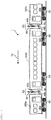
- FIG. 1 is a side view of a formation vehicle provided with inter-vehicle body damper devices according to Embodiment 1 of the invention.
- a formation vehicle 1 includes 5 vehicles which are a leading vehicle 20 coupled at one end of the formation vehicle 1, a trailing vehicle 40 coupled at the other end of the formation vehicle 1, and a first intermediate vehicle 30a, a second intermediate vehicle 30b, and a third intermediate vehicle 30c which are provided between the leading vehicle 20 and the trailing vehicle 40.
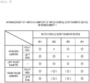
- a first inter-vehicle body damper device A1 constituted by dampers bridged in an up-down direction, a front-rear direction, a left-right direction between the vehicles is provided between the leading vehicle 20 and the first intermediate vehicle 30a and between the third intermediate vehicle 30c and the trailing vehicle 40 (coupling portions).
- a portion (position) where the inter-vehicle body damper device is provided is between a vehicle and a vehicle or is referred to as a coupling portion between a vehicle and a vehicle.
- the second intermediate vehicle 30b is provided with a second inter-vehicle body damper device A2 on a front side thereof and a third inter-vehicle body damper device A3 on a rear side thereof.
- the second intermediate vehicle 30b is coupled to the first intermediate vehicle 30a via the second inter-vehicle body damper device A2 and is coupled to the third intermediate vehicle 30c via the third inter-vehicle body damper device A3.
- the formation vehicle may be made up of 6 vehicles or more in which another vehicle is coupled between the second intermediate vehicle 30b and the first intermediate vehicle 30a or between the second intermediate vehicle 30b and the third intermediate vehicle 30c.
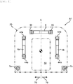
- FIG. 2 is a schematic view of the first inter-vehicle body damper device provided between the leading vehicle and the first intermediate vehicle and between the third intermediate vehicle and the trailing vehicle.
- the first inter-vehicle body damper device A1 includes a pair of up-down dampers 4a (4b) that suppresses relative displacement in the up-down direction between two vehicles, one left-right damper 8 that suppresses relative displacement in the left-right direction between the two vehicles, and a pair of front-rear dampers 7a (7b) that suppresses relative displacement in the front-rear direction between the two vehicles.
- the up-down damper 4a and the front-rear damper 7a are provided on a right side 78 of a penetration-path 50, and the up-down damper 4b and the front-rear damper 7b are provided on a left side 79 of the penetration-path 50.
- the left-right damper 8 is provided above the penetration-path 50.
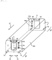
- FIG. 3 is a schematic view of the second inter-vehicle body damper device provided at one end in the longitudinal direction of the second intermediate vehicle
- FIG. 4 is a schematic view of the third inter-vehicle body damper device provided at the other end in the longitudinal direction of the second intermediate vehicle
- FIG. 5 is a schematic view (perspective view) of the second intermediate vehicle provided with the second damper device on the front side and the third inter-vehicle body damper device on the rear side.
- the second inter-vehicle body damper device A2 includes the up-down damper 4b that suppresses the relative displacement in the up-down direction between two vehicles and that is provided only on the left side 79 (one side in the width direction of the end plate) of the penetration-path 50 provided in one end plate 2 in the longitudinal direction of the second intermediate vehicle 30b, the left-right damper 8 that suppresses the relative displacement in the left-right direction between the two vehicles, and a pair of (two) front-rear dampers 7a (7b) that suppresses the relative displacement in the front-rear direction between the two vehicles.
- the third inter-vehicle body damper device A3 includes the up-down damper 4a that suppresses the relative displacement in the up-down direction between two vehicles and that is provided only on the right side 78 (the other side in the width direction of the end plate) of the penetration-path 50 provided in the other end plate 3 in the longitudinal direction of the second intermediate vehicle 30b, the left-right damper 8 that suppresses the relative displacement in the left-right direction between the two vehicles, and a pair of (two) front-rear dampers 7a (7b) that suppresses the relative displacement in the front-rear direction between the two vehicles.
- the up-down damper 4b provided on the left side 79 of the penetration-path 50 in the end plate 2 provided at one end in a traveling direction 77 and the up-down damper 4a provided on the right side 78 of the penetration-path 50 in the end plate 3 provided at the other end in the traveling direction 77 are provided diagonally with respect to a plane including a center line C intersecting the width direction of the vehicle body.
- FIG. 6 is a schematic view showing a state in which the first intermediate vehicle to the third intermediate vehicle of the formation vehicle traveling at a high speed vibrate in the up-down direction in a side view.
- a truck 55 vibrates in the up-down direction due to the track irregularity in the up-down direction and the like.
- the first intermediate vehicle 30a, the second intermediate vehicle 30b, and the third intermediate vehicle 30c, which are supported by the truck 55 that vibrates in the up-down direction, are vibrated in the up-down direction due to the truck 55 and bending vibration is generated.
- the bending vibration having a phase difference is generated between the front and rear vehicles such that a central portion in the longitudinal direction of the second intermediate vehicle 30b is displaced upward and a central portions in the longitudinal direction of the first intermediate vehicle 30a and the third intermediate vehicle 30c are displaced downward (see FIG. 6 ).
- the bending vibration having no phase difference is generated between the front and rear vehicles such that the central portions in the longitudinal direction of the second intermediate vehicle 30b, the first intermediate vehicle 30a and the third intermediate vehicle 30c are displaced in the same direction (not shown).
- Dotted lines 300a, 300b, and 300c schematically show a state in which the first intermediate vehicle 30a, the second intermediate vehicle 30b, and the third intermediate vehicle 30c are deformed along with the bending vibration, respectively.
- a downward speed is generated at both ends in the front-rear direction of the second intermediate vehicle 30b, and an upward speed is generated at a rear end of the first intermediate vehicle 30a and a front end of the third intermediate vehicle 30c.
- the up-down damper 4b of the second inter-vehicle body damper device A2 and the up-down damper 4a of the third inter-vehicle body damper device A3 generate a relative speed that expands and contracts in the up-down direction, and a damping force 66 in a direction canceling the relative speed is generated. Since the vibration in the up-down direction of the first intermediate vehicle 30a, the second intermediate vehicle 30b, and the third intermediate vehicle 30c is suppressed by the damping force 66 of the up-down dampers 4a (4b), the riding comfort can be improved while the number of the dampers is reduced, the manufacturing and maintenance costs associated with the dampers can be decreased.
- FIG. 7 is a schematic view showing a state in which the first intermediate vehicle to the third intermediate vehicle (corresponding to a part D of FIG. 1 ) of the formation vehicle traveling at a high speed vibrate in the left-right direction and a yaw direction in a top view.
- the truck 55 vibrates in the left-right direction due to the track irregularity in the left-right direction and the like.
- the vehicle bodies of the first intermediate vehicle 30a, the second intermediate vehicle 30b, and the third intermediate vehicle 30c which are supported by the truck 55 that vibrates in the left-right direction, are vibrated in the left-right direction due to the truck 55 and vibrate in the left-right direction and the yaw direction.
- Dotted lines 310a, 310b, and 310c shown in in FIG. 7 schematically show vibration 90 in the yaw direction of the first intermediate vehicle 30a, the second intermediate vehicle 30b, and the third intermediate vehicle 30c, respectively.
- a state is shown in which the rear end of the first intermediate vehicle 30a vibrates to the right side 78 and the front end of the second intermediate vehicle 30b vibrates to the left side 79.
- a state is shown in which the rear end of the second intermediate vehicle 30b vibrates to the right side 78 and the front end of the third intermediate vehicle 30c vibrates to the left side 79.
- the vibration in the yaw direction caused by the vibration in the left-right direction of the first intermediate vehicle 30a, the second intermediate vehicle 30b, and the third intermediate vehicle 30c is reduced, the riding comfort can be improved while the number of the dampers can be reduced and the manufacturing and maintenance costs associated with the dampers can be decreased.
- FIG. 8 is a schematic view showing a state in which the second inter-vehicle body damper device and the third inter-vehicle body damper device of the formation vehicle traveling at a high speed overlap each other in the longitudinal direction of the formation vehicle and the adjacent vehicles vibrate in the roll direction.
- the first intermediate vehicle 30a, the second intermediate vehicle 30b, and the third intermediate vehicle 30c vibrate around an axis (roll direction) along the longitudinal direction thereof, due to canting of the track or track irregularity.
- Dotted lines shown in FIG. 8 schematically show a state in which the second intermediate vehicle 30b vibrates in the roll direction, and a dashed line shows the first intermediate vehicle 30a and the third intermediate vehicle 30c.
- vibration (displacement) 91 in the roll direction is generated at the second intermediate vehicle 30b and the leading vehicle 20
- a relative displacement in the roll direction occurs between the adjacent first intermediate vehicle 30a and the adjacent third intermediate vehicle 30c.
- the up-down damper 4b and the left-right damper 8 of the second inter-vehicle body A2, and up-down damper 4a and the left-right damper 8 of the third inter-vehicle body damper device A3 expand and contract according to the roll displacement.
- the vibration 91 in the roll direction of the second intermediate vehicle 30b can be suppressed to improve the riding comfort.
- the up-down damper 4b of the second inter-vehicle body damper device A2 provided on the front side of the second intermediate vehicle 30b and the up-down damper 4a of the third inter-vehicle body damper device A3 provided on the rear side of the second intermediate vehicle 30b are provided diagonally with respect to a plane including a center line C intersecting the width direction of the vehicle body.
- the riding comfort can be improved while the number of the dampers is reduced and the manufacturing and maintenance costs associated with the dampers can be decreased.
- the first inter-vehicle body damper device A1 provided between the leading vehicle 20 and the first intermediate vehicle 30a and between the third intermediate vehicle 30c and the trailing vehicle 40 includes a pair of up-down dampers 4a (4b), the vibration in the roll direction is converted into the vibration in the up-down direction so as to be reduced. Therefore, since the occurrence of vibration in the up-down direction caused by the vibration in the roll direction can be suppressed, the riding comfort can be improved.
- Embodiment 1 an example is shown in which the first inter-vehicle body damper device A1 including the pair of up-down dampers 4a (4b) is provided at a coupling portion between the leading vehicle 20 and the first intermediate vehicle 30a or a coupling portion between the third intermediate vehicle 30c and the trailing vehicle 40.
- the first inter-vehicle body damper device A1 is not limited to be provided at the coupling portions between the vehicles at both ends of the formation vehicle and the intermediate vehicles coupled to the vehicles at both ends, and may be provided at, for example, a coupling portion between a first class (intermediate) vehicle that requires a higher riding comfort or an intermediate vehicle in which riding comfort is easily reduced due to fluid force acting on a current collector mounted on a roof and another intermediate vehicle coupled to this intermediate vehicle.
- the left-right dampers 8 of the first inter-vehicle body damper device A1, the second inter-vehicle body damper device A2, and the third inter-vehicle body damper device A3 are provided above the penetration-path 50, is shown Embodiment 1, it is not limited thereto, and the left-right damper 8 may be provided below the penetration-path 50.
- the first inter-vehicle body damper device A1 are provided with a pair (two) of the front-rear dampers 7a (7b), thereby suppressing the vibration in the left-right direction and improving the riding comfort.
- the front-rear dampers 7a (7b) may be omitted.
- Embodiment 2 a formation vehicle provided with inter-vehicle body damper devices according to Embodiment 2 of the invention will be described with reference to the drawings.
- description of the various dampers described in Embodiment 1 and description of parts common to those in Embodiment 1 will be omitted, and specific configurations of Embodiment 2 will be described.
- the formation vehicle provided with the inter-vehicle body damper devices according to Embodiment 2 is characterized in that the second inter-vehicle body damper device A2 is provided instead of the third inter-vehicle body damper device A3 described in Embodiment 1. That is, the inter-vehicle body damper devices according to Embodiment 2 include the second vehicle body damper devices A2 on the front side and the rear side of the second intermediate vehicle 30b, and the up-down damper 4b is provided on the left side 79 of the penetration-path 50 provided in the end plate 2 and the end plate 3 of the second intermediate vehicle 30b.
- Embodiment 1 in the formation vehicle provided with the vehicle body damper devices according to Embodiment 2, the number of the dampers is reduced, the manufacturing and maintenance costs associated with the dampers can be decreased, the bending vibration and the vibration in the roll direction of the vehicle body can be reduced, the vibration in the left-right direction and the vibration in the yaw direction of the vehicle body can be reduced, and the riding comfort of the vehicle can be improved.
- Embodiment 2 since the up-down damper 4b is provided only on one side of the end plate, an operator can handle the up-down dampers 4b from only one side of the formation vehicle 1 when installing the up-down damper 4b during manufacturing and inspecting or exchanging during the maintenance work, so that the manufacturing and operation efficiency can be improved.
Landscapes
- Engineering & Computer Science (AREA)
- Mechanical Engineering (AREA)
- Vibration Prevention Devices (AREA)
Claims (5)
- Formationsfahrzeug (1), umfassend:ein Führungsfahrzeug (20);ein erstes Zwischenfahrzeug (30a), das an das Führungsfahrzeug gekuppelt ist (20);ein Nachlauffahrzeug (40);ein drittes Zwischenfahrzeug (30c), das an das Nachlauffahrzeug (40) gekuppelt ist;ein zweites Zwischenfahrzeug (30b), das zwischen das erste Zwischenfahrzeug (30a) und das dritte Zwischenfahrzeug (30c) gekuppelt ist;erste Zwischenfahrzeugkörperdämpfvorrichtungen (A1), die zwischen dem Führungsfahrzeug (20) und dem ersten Zwischenfahrzeug (30a) sowie zwischen dem Nachlauffahrzeug (40) und dem dritten Zwischenfahrzeug (30c) bereitgestellt sind; undweitere Zwischenfahrzeugkörperdämpfvorrichtungen (A2, A3), die an beiden Enden in einer Längsrichtung (77) des zweiten Zwischenfahrzeugs (30b) bereitgestellt sind, dadurch gekennzeichnet, dassdie ersten Zwischenfahrzeugkörperdämpfvorrichtungen (A1) jeweils zwei Oben-unten-Dämpfer (4a, 4b) und einen Links-rechts-Dämpfer (8) umfassen, die eine Überbrückung jeweils zwischen dem Führungsfahrzeug (20) und dem ersten Zwischenfahrzeug (30a) sowie zwischen dem Nachlauffahrzeug (40) und dem dritten Zwischenfahrzeug (30c) bereitstellen, unddie weitere Zwischenfahrzeugkörperdämpfvorrichtung an jedem Ende in der Längsrichtung (77) des zweiten Zwischenfahrzeugs (30b) einen Oben-unten-Dämpfer (4a, 4b) und einen Links-rechts-Dämpfer (8) umfasst, die eine Überbrückung zwischen jedem Ende des zweiten Zwischenfahrzeugs (30b) und dem jeweiligen daran gekuppelten Fahrzeug (30a, 30c) bereitstellen.
- Formationsfahrzeug (1) nach Anspruch 1, wobei
die weitere Zwischenfahrzeugkörperdämpfvorrichtung umfasst:eine zweite Zwischenfahrzeugkörperdämpfvorrichtung (A2), die den Oben-unten-Dämpfer (4b) an einem Ende in der Längsrichtung (77) des zweiten Zwischenfahrzeugs (30b) bereitgestellt und an einer Seite in der Breitenrichtung einer Endplatte (2) des zweiten Zwischenfahrzeugs (30b) bereitgestellt umfasst, undeine dritte Zwischenfahrzeugkörperdämpfvorrichtung (A3), die den Oben-unten-Dämpfer (4b) an dem anderen Ende in der Längsrichtung (77) des zweiten Zwischenfahrzeugs (30b) bereitgestellt und auf der anderen Seite in der Breitenrichtung einer entgegengesetzten Endplatte (3) des zweiten Zwischenfahrzeugs bereitgestellt umfasst. - Formationsfahrzeug (1) nach Anspruch 1, wobei
jeder Oben-unten-Dämpfer (4a, 4b) der weiteren Zwischenfahrzeugkörperdämpfvorrichtung auf einer Seite in der Breitenrichtung einer entsprechenden Endplatte (2, 3) des zweiten Zwischenfahrzeugs (30b) bereitgestellt ist. - Formationsfahrzeug (1) nach Anspruch 2 oder 3, wobeieine der ersten Zwischenfahrzeugkörperdämpfvorrichtungen (A1) zwei Vorn-hinten-Dämpfer (7a, 7b) umfasst, die eine Überbrückung zwischen dem Führungsfahrzeug (20) und dem ersten Zwischenfahrzeug (30a) bereitstellen, unddie andere der ersten Zwischenfahrzeugkörperdämpfvorrichtungen (A1) zwei Vornhinten-Dämpfer (7a, 7b) umfasst, die eine Überbrückung zwischen dem Nachlauffahrzeug (40) und dem dritten Zwischenfahrzeug (30c) bereitstellt.
- Formationsfahrzeug (1) nach Anspruch 4, wobei
die Links-rechts-Dämpfer (8) der ersten Zwischenfahrzeugkörperdämpfvorrichtungen (A1) oberhalb eines Penetrationspfads bereitgestellt sind, der das Führungsfahrzeug (20) und das ersten Zwischenfahrzeug (30a) verbindet und das Nachlauffahrzeug (40) und das dritte Zwischenfahrzeug (30c) verbindet.
Applications Claiming Priority (1)
| Application Number | Priority Date | Filing Date | Title |
|---|---|---|---|
| PCT/JP2016/071300 WO2018016035A1 (ja) | 2016-07-20 | 2016-07-20 | 車体間ダンパ装置を備える編成車両 |
Publications (3)
| Publication Number | Publication Date |
|---|---|
| EP3489108A1 EP3489108A1 (de) | 2019-05-29 |
| EP3489108A4 EP3489108A4 (de) | 2020-03-25 |
| EP3489108B1 true EP3489108B1 (de) | 2021-10-27 |
Family
ID=60991990
Family Applications (1)
| Application Number | Title | Priority Date | Filing Date |
|---|---|---|---|
| EP16909510.6A Active EP3489108B1 (de) | 2016-07-20 | 2016-07-20 | Zusammengebautes fahrzeug mit einer zwischenkörperdämpfervorrichtung |
Country Status (3)
| Country | Link |
|---|---|
| EP (1) | EP3489108B1 (de) |
| JP (1) | JP6669866B2 (de) |
| WO (1) | WO2018016035A1 (de) |
Families Citing this family (1)
| Publication number | Priority date | Publication date | Assignee | Title |
|---|---|---|---|---|
| CN113002581B (zh) * | 2021-03-26 | 2023-02-21 | 中车青岛四方机车车辆股份有限公司 | 车端抗侧滚减振装置及轨道车辆、列车 |
Family Cites Families (8)
| Publication number | Priority date | Publication date | Assignee | Title |
|---|---|---|---|---|
| JPS567577Y2 (de) * | 1978-06-08 | 1981-02-19 | ||
| JP2000302038A (ja) * | 1999-04-23 | 2000-10-31 | Hitachi Ltd | 鉄道車両用の車体動揺抑制装置 |
| JP3586808B2 (ja) * | 1999-07-01 | 2004-11-10 | 日本車輌製造株式会社 | 鉄道車両の車体間ダンパ装置 |
| JP4249659B2 (ja) * | 2004-05-25 | 2009-04-02 | 近畿車輌株式会社 | 車体の連接装置 |
| JP5094029B2 (ja) * | 2006-03-22 | 2012-12-12 | 川崎重工業株式会社 | 車両の車体間安定化装置 |
| JP5209220B2 (ja) * | 2007-02-16 | 2013-06-12 | 東海旅客鉄道株式会社 | 鉄道車両の連結部構造 |
| JP2012148723A (ja) * | 2011-01-21 | 2012-08-09 | Railway Technical Research Institute | 車両間ダンパ装置 |
| JP5643124B2 (ja) * | 2011-01-28 | 2014-12-17 | 公益財団法人鉄道総合技術研究所 | 車両間ダンパ装置 |
-
2016
- 2016-07-20 EP EP16909510.6A patent/EP3489108B1/de active Active
- 2016-07-20 JP JP2018528151A patent/JP6669866B2/ja active Active
- 2016-07-20 WO PCT/JP2016/071300 patent/WO2018016035A1/ja not_active Ceased
Also Published As
| Publication number | Publication date |
|---|---|
| JP6669866B2 (ja) | 2020-03-18 |
| WO2018016035A1 (ja) | 2018-01-25 |
| EP3489108A4 (de) | 2020-03-25 |
| JPWO2018016035A1 (ja) | 2019-04-25 |
| EP3489108A1 (de) | 2019-05-29 |
Similar Documents
| Publication | Publication Date | Title |
|---|---|---|
| JP6057171B2 (ja) | サスペンションフレームの構造 | |
| JP2015030375A (ja) | 自動車の車体前部構造 | |
| JP2014521549A (ja) | 列車用サスペンションシステム | |
| EP3489108B1 (de) | Zusammengebautes fahrzeug mit einer zwischenkörperdämpfervorrichtung | |
| JP5872962B2 (ja) | 自動車の車体前部構造 | |
| CN107207019B (zh) | 用于轨道车辆的两个纵向构件的连接构件 | |
| JP5643124B2 (ja) | 車両間ダンパ装置 | |
| JP6512038B2 (ja) | 車両前部構造 | |
| JP2003320931A (ja) | 鉄道車両振動抑制装置 | |
| JP6671106B2 (ja) | 鉄道車両用ヨーダンパ装置 | |
| JP5209220B2 (ja) | 鉄道車両の連結部構造 | |
| JP2014000899A (ja) | エンジンの支持構造 | |
| KR101252547B1 (ko) | 철도차량용 현가장치 | |
| CN105711607A (zh) | 用于控制机车车体的刚性和减振的装置 | |
| JP2012148723A (ja) | 車両間ダンパ装置 | |
| CN207932182U (zh) | 发电机组运输底架 | |
| JP2014141257A (ja) | 車両間ダンパ装置 | |
| CN106005059B (zh) | 整流装置 | |
| CN106005058B (zh) | 整流装置 | |
| JP6320224B2 (ja) | 自動車の前部車体構造 | |
| JP2017047738A (ja) | アンダーランプロテクタ | |
| JP6780486B2 (ja) | 車両前部構造 | |
| JP2006312349A (ja) | 車両中央部における床下骨格構造 | |
| JP7135873B2 (ja) | 車両におけるセパレータバーの組付構造 | |
| WO2015086907A1 (en) | Bogie and carriage structure for rail vehicle |
Legal Events
| Date | Code | Title | Description |
|---|---|---|---|
| STAA | Information on the status of an ep patent application or granted ep patent |
Free format text: STATUS: THE INTERNATIONAL PUBLICATION HAS BEEN MADE |
|
| PUAI | Public reference made under article 153(3) epc to a published international application that has entered the european phase |
Free format text: ORIGINAL CODE: 0009012 |
|
| STAA | Information on the status of an ep patent application or granted ep patent |
Free format text: STATUS: REQUEST FOR EXAMINATION WAS MADE |
|
| 17P | Request for examination filed |
Effective date: 20190107 |
|
| AK | Designated contracting states |
Kind code of ref document: A1 Designated state(s): AL AT BE BG CH CY CZ DE DK EE ES FI FR GB GR HR HU IE IS IT LI LT LU LV MC MK MT NL NO PL PT RO RS SE SI SK SM TR |
|
| AX | Request for extension of the european patent |
Extension state: BA ME |
|
| DAV | Request for validation of the european patent (deleted) | ||
| DAX | Request for extension of the european patent (deleted) | ||
| A4 | Supplementary search report drawn up and despatched |
Effective date: 20200226 |
|
| RIC1 | Information provided on ipc code assigned before grant |
Ipc: B61G 5/02 20060101AFI20200220BHEP |
|
| GRAP | Despatch of communication of intention to grant a patent |
Free format text: ORIGINAL CODE: EPIDOSNIGR1 |
|
| STAA | Information on the status of an ep patent application or granted ep patent |
Free format text: STATUS: GRANT OF PATENT IS INTENDED |
|
| INTG | Intention to grant announced |
Effective date: 20210518 |
|
| GRAS | Grant fee paid |
Free format text: ORIGINAL CODE: EPIDOSNIGR3 |
|
| GRAA | (expected) grant |
Free format text: ORIGINAL CODE: 0009210 |
|
| STAA | Information on the status of an ep patent application or granted ep patent |
Free format text: STATUS: THE PATENT HAS BEEN GRANTED |
|
| AK | Designated contracting states |
Kind code of ref document: B1 Designated state(s): AL AT BE BG CH CY CZ DE DK EE ES FI FR GB GR HR HU IE IS IT LI LT LU LV MC MK MT NL NO PL PT RO RS SE SI SK SM TR |
|
| REG | Reference to a national code |
Ref country code: GB Ref legal event code: FG4D |
|
| REG | Reference to a national code |
Ref country code: CH Ref legal event code: EP |
|
| REG | Reference to a national code |
Ref country code: DE Ref legal event code: R096 Ref document number: 602016065609 Country of ref document: DE |
|
| REG | Reference to a national code |
Ref country code: AT Ref legal event code: REF Ref document number: 1441539 Country of ref document: AT Kind code of ref document: T Effective date: 20211115 |
|
| REG | Reference to a national code |
Ref country code: IE Ref legal event code: FG4D |
|
| REG | Reference to a national code |
Ref country code: LT Ref legal event code: MG9D |
|
| REG | Reference to a national code |
Ref country code: NL Ref legal event code: MP Effective date: 20211027 |
|
| REG | Reference to a national code |
Ref country code: AT Ref legal event code: MK05 Ref document number: 1441539 Country of ref document: AT Kind code of ref document: T Effective date: 20211027 |
|
| PG25 | Lapsed in a contracting state [announced via postgrant information from national office to epo] |
Ref country code: RS Free format text: LAPSE BECAUSE OF FAILURE TO SUBMIT A TRANSLATION OF THE DESCRIPTION OR TO PAY THE FEE WITHIN THE PRESCRIBED TIME-LIMIT Effective date: 20211027 Ref country code: LT Free format text: LAPSE BECAUSE OF FAILURE TO SUBMIT A TRANSLATION OF THE DESCRIPTION OR TO PAY THE FEE WITHIN THE PRESCRIBED TIME-LIMIT Effective date: 20211027 Ref country code: FI Free format text: LAPSE BECAUSE OF FAILURE TO SUBMIT A TRANSLATION OF THE DESCRIPTION OR TO PAY THE FEE WITHIN THE PRESCRIBED TIME-LIMIT Effective date: 20211027 Ref country code: BG Free format text: LAPSE BECAUSE OF FAILURE TO SUBMIT A TRANSLATION OF THE DESCRIPTION OR TO PAY THE FEE WITHIN THE PRESCRIBED TIME-LIMIT Effective date: 20220127 Ref country code: AT Free format text: LAPSE BECAUSE OF FAILURE TO SUBMIT A TRANSLATION OF THE DESCRIPTION OR TO PAY THE FEE WITHIN THE PRESCRIBED TIME-LIMIT Effective date: 20211027 |
|
| PG25 | Lapsed in a contracting state [announced via postgrant information from national office to epo] |
Ref country code: IS Free format text: LAPSE BECAUSE OF FAILURE TO SUBMIT A TRANSLATION OF THE DESCRIPTION OR TO PAY THE FEE WITHIN THE PRESCRIBED TIME-LIMIT Effective date: 20220227 Ref country code: SE Free format text: LAPSE BECAUSE OF FAILURE TO SUBMIT A TRANSLATION OF THE DESCRIPTION OR TO PAY THE FEE WITHIN THE PRESCRIBED TIME-LIMIT Effective date: 20211027 Ref country code: PT Free format text: LAPSE BECAUSE OF FAILURE TO SUBMIT A TRANSLATION OF THE DESCRIPTION OR TO PAY THE FEE WITHIN THE PRESCRIBED TIME-LIMIT Effective date: 20220228 Ref country code: PL Free format text: LAPSE BECAUSE OF FAILURE TO SUBMIT A TRANSLATION OF THE DESCRIPTION OR TO PAY THE FEE WITHIN THE PRESCRIBED TIME-LIMIT Effective date: 20211027 Ref country code: NO Free format text: LAPSE BECAUSE OF FAILURE TO SUBMIT A TRANSLATION OF THE DESCRIPTION OR TO PAY THE FEE WITHIN THE PRESCRIBED TIME-LIMIT Effective date: 20220127 Ref country code: NL Free format text: LAPSE BECAUSE OF FAILURE TO SUBMIT A TRANSLATION OF THE DESCRIPTION OR TO PAY THE FEE WITHIN THE PRESCRIBED TIME-LIMIT Effective date: 20211027 Ref country code: LV Free format text: LAPSE BECAUSE OF FAILURE TO SUBMIT A TRANSLATION OF THE DESCRIPTION OR TO PAY THE FEE WITHIN THE PRESCRIBED TIME-LIMIT Effective date: 20211027 Ref country code: HR Free format text: LAPSE BECAUSE OF FAILURE TO SUBMIT A TRANSLATION OF THE DESCRIPTION OR TO PAY THE FEE WITHIN THE PRESCRIBED TIME-LIMIT Effective date: 20211027 Ref country code: GR Free format text: LAPSE BECAUSE OF FAILURE TO SUBMIT A TRANSLATION OF THE DESCRIPTION OR TO PAY THE FEE WITHIN THE PRESCRIBED TIME-LIMIT Effective date: 20220128 Ref country code: ES Free format text: LAPSE BECAUSE OF FAILURE TO SUBMIT A TRANSLATION OF THE DESCRIPTION OR TO PAY THE FEE WITHIN THE PRESCRIBED TIME-LIMIT Effective date: 20211027 |
|
| REG | Reference to a national code |
Ref country code: DE Ref legal event code: R097 Ref document number: 602016065609 Country of ref document: DE |
|
| PG25 | Lapsed in a contracting state [announced via postgrant information from national office to epo] |
Ref country code: SM Free format text: LAPSE BECAUSE OF FAILURE TO SUBMIT A TRANSLATION OF THE DESCRIPTION OR TO PAY THE FEE WITHIN THE PRESCRIBED TIME-LIMIT Effective date: 20211027 Ref country code: SK Free format text: LAPSE BECAUSE OF FAILURE TO SUBMIT A TRANSLATION OF THE DESCRIPTION OR TO PAY THE FEE WITHIN THE PRESCRIBED TIME-LIMIT Effective date: 20211027 Ref country code: RO Free format text: LAPSE BECAUSE OF FAILURE TO SUBMIT A TRANSLATION OF THE DESCRIPTION OR TO PAY THE FEE WITHIN THE PRESCRIBED TIME-LIMIT Effective date: 20211027 Ref country code: EE Free format text: LAPSE BECAUSE OF FAILURE TO SUBMIT A TRANSLATION OF THE DESCRIPTION OR TO PAY THE FEE WITHIN THE PRESCRIBED TIME-LIMIT Effective date: 20211027 Ref country code: DK Free format text: LAPSE BECAUSE OF FAILURE TO SUBMIT A TRANSLATION OF THE DESCRIPTION OR TO PAY THE FEE WITHIN THE PRESCRIBED TIME-LIMIT Effective date: 20211027 Ref country code: CZ Free format text: LAPSE BECAUSE OF FAILURE TO SUBMIT A TRANSLATION OF THE DESCRIPTION OR TO PAY THE FEE WITHIN THE PRESCRIBED TIME-LIMIT Effective date: 20211027 |
|
| PLBE | No opposition filed within time limit |
Free format text: ORIGINAL CODE: 0009261 |
|
| STAA | Information on the status of an ep patent application or granted ep patent |
Free format text: STATUS: NO OPPOSITION FILED WITHIN TIME LIMIT |
|
| 26N | No opposition filed |
Effective date: 20220728 |
|
| PG25 | Lapsed in a contracting state [announced via postgrant information from national office to epo] |
Ref country code: AL Free format text: LAPSE BECAUSE OF FAILURE TO SUBMIT A TRANSLATION OF THE DESCRIPTION OR TO PAY THE FEE WITHIN THE PRESCRIBED TIME-LIMIT Effective date: 20211027 |
|
| PG25 | Lapsed in a contracting state [announced via postgrant information from national office to epo] |
Ref country code: SI Free format text: LAPSE BECAUSE OF FAILURE TO SUBMIT A TRANSLATION OF THE DESCRIPTION OR TO PAY THE FEE WITHIN THE PRESCRIBED TIME-LIMIT Effective date: 20211027 |
|
| PG25 | Lapsed in a contracting state [announced via postgrant information from national office to epo] |
Ref country code: MC Free format text: LAPSE BECAUSE OF FAILURE TO SUBMIT A TRANSLATION OF THE DESCRIPTION OR TO PAY THE FEE WITHIN THE PRESCRIBED TIME-LIMIT Effective date: 20211027 |
|
| REG | Reference to a national code |
Ref country code: CH Ref legal event code: PL |
|
| REG | Reference to a national code |
Ref country code: BE Ref legal event code: MM Effective date: 20220731 |
|
| PG25 | Lapsed in a contracting state [announced via postgrant information from national office to epo] |
Ref country code: LU Free format text: LAPSE BECAUSE OF NON-PAYMENT OF DUE FEES Effective date: 20220720 Ref country code: LI Free format text: LAPSE BECAUSE OF NON-PAYMENT OF DUE FEES Effective date: 20220731 Ref country code: CH Free format text: LAPSE BECAUSE OF NON-PAYMENT OF DUE FEES Effective date: 20220731 |
|
| PG25 | Lapsed in a contracting state [announced via postgrant information from national office to epo] |
Ref country code: BE Free format text: LAPSE BECAUSE OF NON-PAYMENT OF DUE FEES Effective date: 20220731 |
|
| PG25 | Lapsed in a contracting state [announced via postgrant information from national office to epo] |
Ref country code: IE Free format text: LAPSE BECAUSE OF NON-PAYMENT OF DUE FEES Effective date: 20220720 |
|
| PG25 | Lapsed in a contracting state [announced via postgrant information from national office to epo] |
Ref country code: HU Free format text: LAPSE BECAUSE OF FAILURE TO SUBMIT A TRANSLATION OF THE DESCRIPTION OR TO PAY THE FEE WITHIN THE PRESCRIBED TIME-LIMIT; INVALID AB INITIO Effective date: 20160720 |
|
| PG25 | Lapsed in a contracting state [announced via postgrant information from national office to epo] |
Ref country code: MK Free format text: LAPSE BECAUSE OF FAILURE TO SUBMIT A TRANSLATION OF THE DESCRIPTION OR TO PAY THE FEE WITHIN THE PRESCRIBED TIME-LIMIT Effective date: 20211027 Ref country code: CY Free format text: LAPSE BECAUSE OF FAILURE TO SUBMIT A TRANSLATION OF THE DESCRIPTION OR TO PAY THE FEE WITHIN THE PRESCRIBED TIME-LIMIT Effective date: 20211027 |
|
| PG25 | Lapsed in a contracting state [announced via postgrant information from national office to epo] |
Ref country code: TR Free format text: LAPSE BECAUSE OF FAILURE TO SUBMIT A TRANSLATION OF THE DESCRIPTION OR TO PAY THE FEE WITHIN THE PRESCRIBED TIME-LIMIT Effective date: 20211027 |
|
| PG25 | Lapsed in a contracting state [announced via postgrant information from national office to epo] |
Ref country code: MT Free format text: LAPSE BECAUSE OF FAILURE TO SUBMIT A TRANSLATION OF THE DESCRIPTION OR TO PAY THE FEE WITHIN THE PRESCRIBED TIME-LIMIT Effective date: 20211027 |
|
| PGFP | Annual fee paid to national office [announced via postgrant information from national office to epo] |
Ref country code: GB Payment date: 20250529 Year of fee payment: 10 |
|
| PGFP | Annual fee paid to national office [announced via postgrant information from national office to epo] |
Ref country code: FR Payment date: 20250610 Year of fee payment: 10 |
|
| PGFP | Annual fee paid to national office [announced via postgrant information from national office to epo] |
Ref country code: DE Payment date: 20250528 Year of fee payment: 10 |
|
| PGFP | Annual fee paid to national office [announced via postgrant information from national office to epo] |
Ref country code: IT Payment date: 20250623 Year of fee payment: 10 |