EP3485536B1 - Anschlussklemme - Google Patents
Anschlussklemme Download PDFInfo
- Publication number
- EP3485536B1 EP3485536B1 EP17732329.2A EP17732329A EP3485536B1 EP 3485536 B1 EP3485536 B1 EP 3485536B1 EP 17732329 A EP17732329 A EP 17732329A EP 3485536 B1 EP3485536 B1 EP 3485536B1
- Authority
- EP
- European Patent Office
- Prior art keywords
- actuating
- clamping
- clamping spring
- actuating lever
- tab
- Prior art date
- Legal status (The legal status is an assumption and is not a legal conclusion. Google has not performed a legal analysis and makes no representation as to the accuracy of the status listed.)
- Active
Links
Images
Classifications
-
- H—ELECTRICITY
- H01—ELECTRIC ELEMENTS
- H01R—ELECTRICALLY-CONDUCTIVE CONNECTIONS; STRUCTURAL ASSOCIATIONS OF A PLURALITY OF MUTUALLY-INSULATED ELECTRICAL CONNECTING ELEMENTS; COUPLING DEVICES; CURRENT COLLECTORS
- H01R4/00—Electrically-conductive connections between two or more conductive members in direct contact, i.e. touching one another; Means for effecting or maintaining such contact; Electrically-conductive connections having two or more spaced connecting locations for conductors and using contact members penetrating insulation
- H01R4/28—Clamped connections, spring connections
- H01R4/48—Clamped connections, spring connections utilising a spring, clip, or other resilient member
- H01R4/4809—Clamped connections, spring connections utilising a spring, clip, or other resilient member using a leaf spring to bias the conductor toward the busbar
- H01R4/48185—Clamped connections, spring connections utilising a spring, clip, or other resilient member using a leaf spring to bias the conductor toward the busbar adapted for axial insertion of a wire end
- H01R4/4819—Clamped connections, spring connections utilising a spring, clip, or other resilient member using a leaf spring to bias the conductor toward the busbar adapted for axial insertion of a wire end the spring shape allowing insertion of the conductor end when the spring is unbiased
- H01R4/4821—Single-blade spring
-
- H—ELECTRICITY
- H01—ELECTRIC ELEMENTS
- H01R—ELECTRICALLY-CONDUCTIVE CONNECTIONS; STRUCTURAL ASSOCIATIONS OF A PLURALITY OF MUTUALLY-INSULATED ELECTRICAL CONNECTING ELEMENTS; COUPLING DEVICES; CURRENT COLLECTORS
- H01R4/00—Electrically-conductive connections between two or more conductive members in direct contact, i.e. touching one another; Means for effecting or maintaining such contact; Electrically-conductive connections having two or more spaced connecting locations for conductors and using contact members penetrating insulation
- H01R4/28—Clamped connections, spring connections
- H01R4/48—Clamped connections, spring connections utilising a spring, clip, or other resilient member
- H01R4/4809—Clamped connections, spring connections utilising a spring, clip, or other resilient member using a leaf spring to bias the conductor toward the busbar
- H01R4/4828—Spring-activating arrangements mounted on or integrally formed with the spring housing
- H01R4/483—Pivoting arrangements, e.g. lever pushing on the spring
-
- H—ELECTRICITY
- H01—ELECTRIC ELEMENTS
- H01R—ELECTRICALLY-CONDUCTIVE CONNECTIONS; STRUCTURAL ASSOCIATIONS OF A PLURALITY OF MUTUALLY-INSULATED ELECTRICAL CONNECTING ELEMENTS; COUPLING DEVICES; CURRENT COLLECTORS
- H01R4/00—Electrically-conductive connections between two or more conductive members in direct contact, i.e. touching one another; Means for effecting or maintaining such contact; Electrically-conductive connections having two or more spaced connecting locations for conductors and using contact members penetrating insulation
- H01R4/28—Clamped connections, spring connections
- H01R4/48—Clamped connections, spring connections utilising a spring, clip, or other resilient member
- H01R4/4809—Clamped connections, spring connections utilising a spring, clip, or other resilient member using a leaf spring to bias the conductor toward the busbar
- H01R4/4828—Spring-activating arrangements mounted on or integrally formed with the spring housing
- H01R4/4835—Mechanically bistable arrangements, e.g. locked by the housing when the spring is biased
-
- H—ELECTRICITY
- H01—ELECTRIC ELEMENTS
- H01R—ELECTRICALLY-CONDUCTIVE CONNECTIONS; STRUCTURAL ASSOCIATIONS OF A PLURALITY OF MUTUALLY-INSULATED ELECTRICAL CONNECTING ELEMENTS; COUPLING DEVICES; CURRENT COLLECTORS
- H01R9/00—Structural associations of a plurality of mutually-insulated electrical connecting elements, e.g. terminal strips or terminal blocks; Terminals or binding posts mounted upon a base or in a case; Bases therefor
- H01R9/22—Bases, e.g. strip, block, panel
- H01R9/24—Terminal blocks
Definitions
- the invention relates to a connection terminal for connecting an electrical conductor, which has a housing, a current bar arranged in the housing, a clamping spring arranged in the housing and a pivotably mounted actuating lever, wherein the clamping spring can be transferred into an open and a closed position when the actuating lever is pivoted, wherein the clamping spring has a clamping leg for clamping a conductor inserted into the housing against the current bar in the closed position.
- An actuating tab is arranged on the clamping leg in such a way that when the clamping spring is transferred from the closed position to the open position, a pressure force F D is applied by the actuating lever to the actuating tab, wherein the actuating tab has a connection area arranged directly on the clamping leg and a pressure area arranged on the connection area, wherein the pressure area is formed at a distance from the clamping leg.
- connection terminals are EP 2 562 878 A2 and the WO 2020/022955 A1 known.
- a clamping spring can be moved into an open position and a closed position by means of an operating lever.
- the operating lever is pivotally mounted in the housing.
- the operating lever has a rounded arm, by means of which the operating lever grips the clamping spring on a tension element formed on the clamping spring in order to move the clamping spring from the closed position to the open position by applying a tensile force.
- the structure of the clamping spring and also of the entire connection terminal is very complex and laborious. The convenience of connecting a conductor is also reduced for a user with such a connection terminal.
- connection terminals are available from the DE 44 08 985 A1 , DE 20 2013 101 582 U1 , EP 3 350 881 A1 and DE 10 2012 110 895 A1 known.
- the invention is therefore based on the object of providing a connection terminal by means of which a secure connection of a conductor can be achieved while at the same time reducing the complexity of the structure of the connection terminal.
- connection terminal is characterized in that the actuating lever is positioned relative to the actuating tab in such a way that the actuating lever is held in a self-locking manner in the open position, wherein the self-locking is formed in that in the open position a pressure point P D acting on the actuating tab when the pressure force F D is applied by means of the actuating lever is arranged above a pivot axis of the actuating lever.
- connection terminal is therefore highly efficient, so that a high level of safety can be achieved when connecting and disconnecting a conductor.
- the ease of use for a user of the connection terminal can also be significantly improved as a result.
- the direct effect on the clamping leg via the actuating tab connected to it also means that the structure of the connection terminal can be less complex.
- the pressure force applied to the actuating tab preferably acts against the direction of insertion of the conductor into the connection terminal and also against the direction of movement of the clamping leg when moving from the closed position to the open position.
- the actuating lever presses against the actuating tab, whereby the actuating tab is also moved, in particular pivoted, together with the clamping leg of the clamping spring arranged on it.
- the contact leg of the clamping spring which is connected to the clamping leg via an arcuate connecting section, preferably remains in its position and is not moved or pivoted when the pressure force is applied to the actuating tab.
- the actuating tab is preferably arranged on one side of the clamping leg.
- the actuating tab is preferably arranged on a transverse side surface of the clamping leg that extends along the length of the clamping leg. The width of the connection terminal can be reduced by connecting the actuating tab to the clamping leg on one side.
- the actuating tab is divided into two areas.
- the actuating tab has a connection area arranged directly on the clamping leg and a pressure area arranged on the connection area, wherein the pressure area is designed at a distance from the clamping leg.
- the pressure area is the area of the actuating tab to which the pressure force is applied by the actuating lever to the actuating tab.
- the pressure area preferably has no direct contact with the clamping leg, but only with the connection area, which is connected to the clamping leg.
- the pressure area is preferably formed in a different plane than the connection area.
- the plane spanned by the pressure area is preferably formed at an angle > 0, preferably at an angle > 45° to the plane spanned by the connection area.
- the pressure area is preferably formed at an angle of 90° to the connection area.
- the pressure area preferably runs along the width of the clamping spring and thus transversely to the longitudinal extension of the clamping spring or the clamping leg of the clamping spring, so that the pressure force acting on the pressure area at an angle of 90° acts along the longitudinal extension of the clamping spring or the clamping leg of the clamping spring. This can prevent the clamping spring from tipping sideways when the pressure force is applied to the actuating tab.
- the actuating tab and the clamping spring are formed as one piece with one another.
- the clamping spring and the actuating tab are preferably formed from a bent metal strip.
- a pin-shaped actuating area is preferably formed on the actuating lever.
- a defined pressure force with a defined pressure point can be applied to the actuating tab.
- the operating lever is positioned in relation to the operating tab in such a way that the operating lever is held in the open position in a self-locking manner.
- the self-locking means that the operating lever can remain in the open position independently and does not have to be held in position by the user.
- the self-locking mechanism is designed such that in the open position a pressure point acting on the actuating tab when the pressure force is applied by means of the actuating lever is arranged above a pivot axis of the actuating lever. This allows the actuating lever to be self-locking without great structural effort.
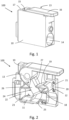
- connection terminal 100 for connecting an electrical conductor not shown here is shown.
- the connection terminal 100 has a housing 10 in which a current bar 11, a clamping spring 12 and an actuating lever 13 are accommodated, as shown in particular in Fig. 2 can be seen.
- the housing 10 is designed in two parts, with the two housing parts being detachably connected to one another via a plug or screw connection.
- a conductor insertion opening 14 is formed in the housing 10, through which a conductor to be connected can be inserted into the connection terminal 100.
- the housing 10 also has an opening 15, through which a part of the actuating lever 13, in particular a handle 16 for actuating the actuating lever 13, protrudes from the housing 10.
- the opening 15 is formed on an upper side 17 of the housing 10.
- the clamping spring 12 has a clamping leg 18 and a contact leg 19, which are connected to one another via an arcuate connecting section 20.
- the clamping spring 12 is mounted in the housing 10 in such a way that the clamping leg 18 is movable, so that the clamping spring 12 can be moved into an open position, in which a conductor to be connected can be inserted into and released from the clamping space formed by the clamping spring 12 and the current bar 11, and into a closed position, in which a conductor to be connected is clamped against the current bar 11 by means of the clamping leg 18.
- the housing 10 has a curved inner contour 21 which is adapted to the shape of the arcuate connecting section 20 so that the arcuate connecting section 20 can fit precisely against the inner contour 21 and thus fixation of the clamping spring 12 in the housing 10 is possible.
- the contact leg 19 is arranged in the housing 10 in a movement-resistant manner so that the contact leg 19 does not move but remains in its position when the clamping spring 12 is transferred to the open position and the closed position.
- a U-shaped projection 22 is arranged on the clamping spring 12, which serves as a stop or push-through protection for a conductor inserted into the housing 10.
- the projection 22 also serves to accommodate the current bar 11, in that the projection 22 has an opening 23 through which the current bar 11 is guided, so that the current bar 11 lies flat against an inner side of the projection 22.
- the projection 22 is formed in one piece with the clamping spring 12, with the projection 22 adjoining the contact leg 19.
- the clamping spring 12 is formed together with the projection 22 from a bent metal strip.
- an actuating tab 24 is arranged on the clamping spring 12, which is arranged on the clamping leg 18 of the clamping spring 12 in such a way that when the clamping spring 12 is transferred from the closed position to the open position, a pressure force F D is applied by the actuating lever 13 to the actuating tab 24.
- the pressure force F D acts opposite to the direction of movement B K or the deflection of the clamping leg 18 during the movement from the closed position to the open position.
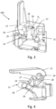
- the clamping spring 12 is shown in the closed position and in Fig. 3 the clamping spring 12 is shown in the open position.
- the actuating tab 24 is connected on one side to the clamping leg 18 of the clamping spring 12, wherein the actuating tab 24 is connected to a transverse side surface 25 of the clamping leg 18 running along the length of the clamping leg 18.
- the actuating tab 24 is formed in one piece with the clamping leg 18 and thus the clamping spring 12.
- the actuating tab 24 is divided into two areas, a connection area 26 and a pressure area 27.
- connection area 26 is the area with which the actuating tab 24 is connected to the clamping leg 18 of the clamping spring 12.
- the connection area 26 runs to the side of the clamping spring 12 and extends from the clamping leg 18 beyond the contact leg 19, so that the connection area 26 overlaps the contact leg 19.
- the pressure area 27 is designed at a distance from the clamping leg 18, so that no direct connection is formed between the pressure area 27 and the clamping leg 18.
- the pressure area 27 is the area in which the pressure force F D is applied by the actuating lever 13 to the actuating tab 24.
- the pressure area 27 is arranged above the contact leg 19.
- the pressure area 27 is designed at an angle of 90° to the connection area 26.
- the pressure area 27 runs along the width of the clamping spring 12 and thus transversely to the longitudinal extension of the clamping spring 12 or the clamping leg 18 and the contact leg 19 of the clamping spring 12, so that the pressure force F D acting at an angle of 90° on the pressure area 27 acts along the longitudinal extension of the clamping spring 12 or the clamping leg 18 of the clamping spring 12.
- the pressure area 27 extends over the entire width of the clamping spring 12.
- a pin-shaped actuating area 28 is formed on the actuating lever 13, which presses directly against the pressure area 27 of the actuating tab 24, as shown in particular in Fig. 3 can be seen.
- the actuating lever 13 rolls with the pin-shaped actuating area 28 on the surface of the pressure area 27 in order to apply the pressure force F D.
- the actuating lever 13 is pivotally mounted about a pivot axis 29 for this purpose.
- the actuating lever 13 is positioned relative to the actuating tab 24 in such a way that the actuating lever 13 is held in the open position in a self-locking manner and thus remains independently in the open position, as shown in Fig. 3 is shown, without a user having to hold the actuating lever 13 in this position.
- a pressure point P D which acts on the actuating tab 24 when the pressure force F D is applied by means of the actuating lever 13 is arranged above the pivot axis 29 in the open position.
- the pressure point P D is the point at which the pin-shaped actuating area 28 of the actuating lever 13 presses with its tip 30 against the pressure area 27 of the actuating tab 24 in the open position.
- the actuating lever 13 is turned back by a user past this pressure point P D.
- connection terminal 100 Housing 10 current bar 11 clamping spring 12 operating lever 13 conductor entry opening 14 opening 15 Handle 16 top 17 clamping leg 18 attachment leg 19 Arched connecting section 20 inner contour 21 Approach 22 opening 23 actuating tab 24 transverse side surface 25 connection area 26 pressure range 27 area of operation 28 swivel axis 29 Great 30 compressive force F D direction of movement of the clamping leg of the clamping spring B K pressure point P D
Landscapes
- Connections Arranged To Contact A Plurality Of Conductors (AREA)
- Coupling Device And Connection With Printed Circuit (AREA)
- Clamps And Clips (AREA)
- Details Of Connecting Devices For Male And Female Coupling (AREA)
Description
- Die Erfindung betrifft eine Anschlussklemme zum Anschließen eines elektrischen Leiters, welche ein Gehäuse, einen in dem Gehäuse angeordneten Strombalken, eine in dem Gehäuse angeordnete Klemmfeder und einen schwenkbar gelagerten Betätigungshebel aufweist, wobei bei einer Verschwenkbewegung des Betätigungshebels die Klemmfeder in eine geöffnete und in eine geschlossene Position überführbar ist, wobei die Klemmfeder einen Klemmschenkel zum Klemmen eines in das Gehäuse eingeführten Leiters gegen den Strombalken in der geschlossenen Position aufweist. An dem Klemmschenkel ist eine Betätigungslasche derart angeordnet, dass bei der Überführung der Klemmfeder von der geschlossenen Position in die geöffnete Position eine Druckkraft FD von dem Betätigungshebel auf die Betätigungslasche aufgebracht ist, wobei die Betätigungslasche einen unmittelbar an dem Klemmschenkel angeordneten Anbindungsbereich und einen an dem Anbindungsbereich angeordneten Druckbereich aufweist, wobei der Druckbereich beabstandet zu dem Klemmschenkel ausgebildet ist
- Entsprechende Anschlussklemmen sind aus der
EP 2 562 878 A2 und derWO 2020/022955 A1 bekannt. Aus derDE 697 03 829 T2 ist eine entsprechende Anschlussklemme bekannt, bei welcher eine Klemmfeder mittels eines Betätigungshebels in eine geöffnete Position und eine geschlossene Position überführbar ist. Der Betätigungshebel ist schwenkbar in dem Gehäuse gelagert. Der Betätigungshebel weist einen abgerundet ausgebildeten Arm auf, mittels welchem der Betätigungshebel die Klemmfeder an einem an der Klemmfeder ausgebildeten Zugelement greift, um die Klemmfeder von der geschlossenen Position in die geöffnete Position durch Aufbringen einer Zugkraft zu überführen. Der Aufbau der Klemmfeder und auch der gesamten Anschlussklemme ist sehr aufwendig und komplex. Auch der Komfort beim Anschließen eines Leiters ist bei einer derartigen Anschlussklemme für einen Benutzer reduziert. - Weitere Anschlussklemmen sind aus der
DE 44 08 985 A1 ,DE 20 2013 101 582 U1 ,EP 3 350 881 A1 undDE 10 2012 110 895 A1 bekannt. - Der Erfindung liegt daher die Aufgabe zugrunde, eine Anschlussklemme zur Verfügung zu stellen, mittels welcher ein sicherer Anschluss eines Leiters bei einer gleichzeitig reduzierten Komplexität im Aufbau der Anschlussklemme erreicht werden kann.
- Die Lösung der Erfindung erfolgt mit den Merkmalen des unabhängigen Anspruchs. Zweckmäßige Ausgestaltungen und vorteilhafte Weiterbildungen der Erfindung sind in den Unteransprüchen angegeben.
- Die Anschlussklemme gemäß der Erfindung zeichnet sich dadurch aus, dass der Betätigungshebel zu der Betätigungslasche derart positioniert ist, dass der Betätigungshebel in der geöffneten Position selbsthemmend gehalten ist, wobei die Selbsthemmung dadurch ausgebildet ist, dass in der geöffneten Position ein beim Aufbringen der Druckkraft FD mittels des Betätigungshebels auf die Betätigungslasche wirkender Druckpunkt PD oberhalb einer Schwenkachse des Betätigungshebels angeordnet ist.
- Erfindungsgemäß ist es nunmehr vorgesehen, dass keine Zugkraft, sondern eine Druckkraft mittels eines Betätigungshebels auf die Betätigungslasche und damit die Klemmfeder aufgebracht wird, um diese zu öffnen. Die Betätigungslasche ist unmittelbar an dem Klemmschenkel der Klemmfeder angeordnet, so dass die auf die Betätigungslasche wirkende Kraft unmittelbar eine Bewegung des Klemmschenkels bewirken kann, ohne von der Klemmfeder unabhängige Zusatzelemente oder zusätzlich an der Klemmfeder vorgesehene Elemente nutzen zu müssen. Hierdurch kann ein Energieverlust der wirkenden Druckkraft zum Betätigen des Klemmschenkels der Klemmfeder verhindert werden. Die Anschlussklemme weist dadurch einen hohen Wirkungsgrad auf, so dass eine hohe Sicherheit beim Anschließen und Lösen eines Leiters erreicht werden kann. Auch der Bedienkomfort für einen Benutzer der Anschlussklemme kann dadurch wesentlich verbessert werden. Durch die unmittelbare Wirkung auf den Klemmschenkel über die daran angebundene Betätigungslasche kann zudem der Aufbau der Anschlussklemme weniger komplex ausgebildet sein. Die auf die Betätigungslasche aufgebrachte Druckkraft wirkt dabei vorzugsweise entgegen der Einführrichtung des Leiters in die Anschlussklemme und auch entgegengesetzt zu der Bewegungsrichtung des Klemmschenkels bei der Bewegung von der geschlossenen Position in die geöffnete Position. Bei einer Verschwenkbewegung des Betätigungshebels drückt der Betätigungshebel gegen die Betätigungslasche, wodurch die Betätigungslasche zusammen mit dem daran angeordneten Klemmschenkel der Klemmfeder ebenfalls bewegt, insbesondere verschwenkt, wird. Der über einen bogenförmigen Verbindungsabschnitt an den Klemmschenkel angebundene Anlageschenkel der Klemmfeder verbleibt hingegen vorzugsweise in seiner Position und wird bei Aufbringen der Druckkraft auf die Betätigungslasche nicht mit bewegt bzw. mit verschwenkt.
- Die Betätigungslasche ist vorzugsweise lediglich einseitig an dem Klemmschenkel angeordnet. Die Betätigungslasche ist vorzugsweise an einer sich entlang der Länge des Klemmschenkels erstreckenden Querseitenfläche des Klemmschenkels angeordnet. Durch die einseitige Anbindung der Betätigungslasche an dem Klemmschenkel kann die Breite der Anschlussklemme reduziert werden.
- Die Betätigungslasche ist in zwei Bereiche unterteilt. Erfindungsgemäß weist die Betätigungslasche einen unmittelbar an dem Klemmschenkel angeordneten Anbindungsbereich und einen an dem Anbindungsbereich angeordneten Druckbereich auf, wobei der Druckbereich beabstandet zu dem Klemmschenkel ausgebildet ist. Der Druckbereich ist der Bereich der Betätigungslasche, auf welchen die Druckkraft von dem Betätigungshebel auf die Betätigungslasche aufgebracht wird. Der Druckbereich hat vorzugsweise keinen direkten Kontakt mit dem Klemmschenkel, sondern nur mit dem Anbindungsbereich, welcher mit dem Klemmschenkel verbunden ist.
- Der Druckbereich ist vorzugsweise in einer anderen Ebene ausgebildet als der Anbindungsbereich. Die durch den Druckbereich aufgespannte Ebene ist vorzugsweise in einem Winkel > 0, bevorzugt in einem Winkel > 45° zu der von dem Anbindungsbereich aufgespannten Ebene ausgebildet. Bevorzugt ist der Druckbereich in einem Winkel von 90° zu dem Anbindungsbereich abgewinkelt ausgebildet. Der Druckbereich verläuft dabei vorzugsweise entlang der Breite der Klemmfeder und damit quer zur Längserstreckung der Klemmfeder bzw. des Klemmschenkels der Klemmfeder, so dass die in einem Winkel von 90° auf den Druckbereich wirkende Druckkraft entlang der Längserstreckung der Klemmfeder bzw. des Klemmschenkels der Klemmfeder wirkt. Ein seitliches Verkippen der Klemmfeder bei Aufbringen der Druckkraft auf die Betätigungslasche kann dadurch verhindert werden.
- Um eine sichere Anbindung der Betätigungslasche an die Klemmfeder und damit eine sichere Übertragung der auf die Betätigungslasche wirkenden Druckkraft auf die Klemmfeder erreichen zu können, ist es bevorzugt vorgesehen, dass die Betätigungslasche und die Klemmfeder einstückig miteinander ausgebildet sind. Die Klemmfeder und die Betätigungslasche sind dabei vorzugsweise aus einem Metallstreifen gebogen ausgebildet.
- Zum Aufbringen der Druckkraft ist an dem Betätigungshebel vorzugsweise ein zapfenförmiger Betätigungsbereich ausgebildet. Mittels des zapfenförmigen Betätigungsbereichs kann eine definierte Druckkraft mit einem definierten Druckpunkt auf die Betätigungslasche aufgebracht werden.
- Um den Bedienkomfort für den Benutzer der Anschlussklemme zu erhöhen, ist der Betätigungshebel zu der Betätigungslasche derart positioniert, dass der Betätigungshebel in der geöffneten Position selbsthemmend gehalten ist. Durch die Selbsthemmung kann der Betätigungshebel in der geöffneten Position eigenständig verbleiben und muss damit nicht von dem Benutzer in der Position gehalten werden.
- Erfindungsgemäß ist die Selbsthemmung derart ausgebildet, dass in der geöffneten Position ein beim Aufbringen der Druckkraft mittels des Betätigungshebels auf die Betätigungslasche wirkender Druckpunkt oberhalb einer Schwenkachse des Betätigungshebels angeordnet ist. Hierdurch kann ohne großen konstruktiven Aufwand eine Selbsthemmung des Betätigungshebels ausgebildet werden.
- Nachfolgend wird die Erfindung unter Bezugnahme auf die anliegenden Zeichnungen anhand einer bevorzugten Ausgestaltung näher erläutert.
- Es zeigen:
- Fig. 1
- eine schematische Darstellung einer Anschlussklemme gemäß der Erfindung,
- Fig. 2
- eine schematische Darstellung der in
Fig. 1 gezeigten Anschlussklemme in einer teilweise geschnitten Ansicht mit der Klemmfeder in der geschlossenen Position, - Fig. 3
- eine schematische Darstellung der in
Fig. 1 gezeigten Anschlussklemme in einer teilweise geschnitten Ansicht mit der Klemmfeder in der geöffneten Position, und - Fig. 4
- eine weitere Darstellung eines Teils der in
Fig. 1 gezeigten Anschlussklemme mit der Klemmfeder in der geschlossenen Position. - In
Fig. 1 ist eine Anschlussklemme 100 zum Anschließen eines hier nicht gezeigten elektrischen Leiters dargestellt. - Die Anschlussklemme 100 weist ein Gehäuse 10 auf, in welchem ein Strombalken 11, eine Klemmfeder 12 und ein Betätigungshebel 13 aufgenommen sind, wie insbesondere in
Fig. 2 zu erkennen ist. Das Gehäuse 10 ist zweiteilig ausgebildet, wobei die beiden Gehäuseteile über eine Steck- oder Schraubverbindung lösbar miteinander verbunden sind. In dem Gehäuse 10 ist eine Leitereinführungsöffnung 14 ausgebildet, über welche ein anzuschließender Leiter in die Anschlussklemme 100 eingeführt werden kann. Das Gehäuse 10 weist zudem eine Öffnung 15 auf, über welche ein Teil des Betätigungshebels 13, insbesondere ein Griff 16 zum Betätigen des Betätigungshebels 13, aus dem Gehäuse 10 herausragt. Die Öffnung 15 ist an einer Oberseite 17 des Gehäuses 10 ausgebildet. - Wie in
Fig. 2 zu erkennen ist, weist die Klemmfeder 12 einen Klemmschenkel 18 und einen Anlageschenkel 19 auf, welche über einen bogenförmigen Verbindungsabschnitt 20 miteinander verbunden sind. Die Klemmfeder 12 ist derart in dem Gehäuse 10 gelagert, dass der Klemmschenkel 18 bewegbar ist, so dass die Klemmfeder 12 in eine geöffnete Position, in welcher ein anzuschließender Leiter in den durch die Klemmfeder 12 und den Strombalken 11 ausgebildeten Klemmraum einführbar und lösbar ist, und in eine geschlossene Position, in welcher ein anzuschließender Leiter mittels des Klemmschenkels 18 gegen die Strombalken 11 geklemmt ist, überführbar ist. - Das Gehäuse 10 weist eine gebogene Innenkontur 21 auf, welche an die Form des bogenförmigen Verbindungsabschnitts 20 angepasst ist, so dass der bogenförmige Verbindungsabschnitt 20 passgenau an der Innenkontur 21 anliegen kann und damit eine Fixierung der Klemmfeder 12 in dem Gehäuse 10 erreichbar ist. Der Anlageschenkel19 ist im Gegensatz zu dem Klemmschenkel 18 bewegungssteif in dem Gehäuse 10 angeordnet, so dass der Anlageschenkel 19 keine Bewegung ausführt, sondern in seiner Position verbleibt, wenn die Klemmfeder 12 in die geöffnete Position und die geschlossene Position überführt wird.
- An der Klemmfeder 12 ist ein U-förmig ausgebildeter Ansatz 22 angeordnet, welcher als Anschlag bzw. Durchsteckschutz für einen in das Gehäuse 10 eingeführten Leiter dient. Ferner dient der Ansatz 22 zur Aufnahme des Strombalkens 11, indem der Ansatz 22 eine Öffnung 23 aufweist, durch welche der Strombalken 11 hindurchgeführt ist, so dass der Strombalken 11 flächig an einer Innenseite des Ansatzes 22 anliegt. Der Ansatz 22 ist einstückig mit der Klemmfeder 12 ausgebildet, wobei der Ansatz 22 an den Anlageschenkel 19 anschließt. Die Klemmfeder 12 ist zusammen mit dem Ansatz 22 aus einem gebogenen Metallstreifen ausgebildet.
- Weiter ist an der Klemmfeder 12 eine Betätigungslasche 24 angeordnet, welche an dem Klemmschenkel 18 der Klemmfeder 12 derart angeordnet ist, dass bei der Überführung der Klemmfeder 12 von der geschlossenen Position in die geöffnete Position eine Druckkraft FD von dem Betätigungshebel 13 auf die Betätigungslasche 24 aufgebracht ist. Zur Überführung der Klemmfeder 12 von der geschlossenen Position in die geöffnete Position wird dadurch keine Kraft unmittelbar auf die Klemmfeder 12 und insbesondere den Klemmschenkel 18 der Klemmfeder 12 aufgebracht, sondern mittelbar über die Betätigungslasche 24. Die Druckkraft FD wirkt dabei entgegengesetzt zu der Bewegungsrichtung BK bzw. der Auslenkung des Klemmschenkels 18 bei der Bewegung von der geschlossenen Position in die geöffnete Position. In
Fig. 2 und4 ist die Klemmfeder 12 in der geschlossenen Position gezeigt und inFig. 3 ist die Klemmfeder 12 in der geöffneten Position gezeigt. - Die Betätigungslasche 24 ist einseitig an dem Klemmschenkel 18 der Klemmfeder 12 angebunden, wobei die Betätigungslasche 24 an einer entlang der Länge des Klemmschenkels 18 verlaufenden Querseitenfläche 25 des Klemmschenkels 18 angebunden ist. Die Betätigungslasche 24 ist bei der hier gezeigten Ausgestaltung einstückig mit dem Klemmschenkel 18 und damit der Klemmfeder 12 ausgebildet.
- Die Betätigungslasche 24 ist in zwei Bereiche unterteilt, einen Anbindungsbereich 26 und einen Druckbereich 27.
- Der Anbindungsbereich 26 ist der Bereich, mit welchem die Betätigungslasche 24 an den Klemmschenkel 18 der Klemmfeder 12 angebunden ist. Der Anbindungsbereich 26 verläuft seitlich der Klemmfeder 12 und erstreckt sich ausgehend von dem Klemmschenkel 18 über den Anlageschenkel 19 hinaus, so dass der Anbindungsbereich 26 den Anlageschenkel 19 überlappt.
- Der Druckbereich 27 ist im Gegensatz zu dem Anbindungsbereich 26 beabstandet zu dem Klemmschenkel 18 ausgebildet, so dass keine direkte Verbindung zwischen dem Druckbereich 27 und dem Klemmschenkel 18 ausgebildet ist. Der Druckbereich 27 ist der Bereich, an welchem die Druckkraft FD von dem Betätigungshebel 13 auf die Betätigungslasche 24 aufgebracht wird. Der Druckbereich 27 ist oberhalb des Anlageschenkels 19 angeordnet. Der Druckbereich 27 ist in einem Winkel von 90° zu dem Anbindungsbereich 26 ausgebildet. Der Druckbereich 27 verläuft dabei entlang der Breite der Klemmfeder 12 und damit quer zur Längserstreckung der Klemmfeder 12 bzw. des Klemmschenkels 18 und des Anlageschenkels 19 der Klemmfeder 12, so dass die in einem Winkel von 90° auf den Druckbereich 27 wirkende Druckkraft FD entlang der Längserstreckung der Klemmfeder 12 bzw. des Klemmschenkels 18 der Klemmfeder 12 wirkt. Der Druckbereich 27 erstreckt sich dabei über die gesamte Breite der Klemmfeder 12.
- Zum Aufbringen der Druckkraft FD ist an dem Betätigungshebel 13 ein zapfenförmiger Betätigungsbereich 28 ausgebildet, welcher unmittelbar gegen den Druckbereich 27 der Betätigungslasche 24 drückt, wie insbesondere in
Fig. 3 zu erkennen ist. Während der Bewegung von der geschlossenen Position in die geöffnete Position rollt der Betätigungshebel 13 mit dem zapfenförmigen Betätigungsbereich 28 an der Fläche des Druckbereichs 27 ab, um die Druckkraft FD aufzubringen. Der Betätigungshebel 13 ist dafür um eine Schwenkachse 29 schwenkbar gelagert. - Der Betätigungshebel 13 ist zu der Betätigungslasche 24 derart positioniert, dass der Betätigungshebel 13 in der geöffneten Position selbsthemmend gehalten ist und damit selbstständig in der geöffneten Position verbleibt, wie sie in
Fig. 3 gezeigt ist, ohne dass ein Benutzer den Betätigungshebel 13 in dieser Position festhalten muss. Zur Ausbildung der Selbsthemmung ist in der geöffneten Position ein beim Aufbringen der Druckkraft FD mittels des Betätigungshebels 13 auf die Betätigungslasche 24 wirkender Druckpunkt PD oberhalb der Schwenkachse 29 angeordnet. Der Druckpunkt PD ist der Punkt, mit welchem der zapfenförmige Betätigungsbereich 28 des Betätigungshebels 13 mit seiner Spitze 30 gegen den Druckbereich 27 der Betätigungslasche 24 in der geöffneten Position drückt. Um die Klemmfeder 12 von der geöffneten Position in die geschlossene Position zu überführen, um den Klemmraum zu schließen, wird der Betätigungshebel 13 von einem Benutzer über diesen Druckpunkt PD zurück gedreht. -
Anschlussklemme 100 Gehäuse 10 Strombalken 11 Klemmfeder 12 Betätigungshebel 13 Leitereinführungsöffnung 14 Öffnung 15 Griff 16 Oberseite 17 Klemmschenkel 18 Anlageschenkel 19 Bogenförmiger Verbindungsabschnitt 20 Innenkontur 21 Ansatz 22 Öffnung 23 Betätigungslasche 24 Querseitenfläche 25 Anbindungsbereich 26 Druckbereich 27 Betätigungsbereich 28 Schwenkachse 29 Spitze 30 Druckkraft FD Bewegungsrichtung des Klemmschenkels der Klemmfeder BK Druckpunkt PD
Claims (4)
- Anschlussklemme (100) zum Anschließen eines elektrischen Leiters, miteinem Gehäuse (10),einem in dem Gehäuse (10) angeordneten Strombalken (11),einer in dem Gehäuse (10) angeordneten Klemmfeder (12), undeinem schwenkbar gelagerten Betätigungshebel (13),wobei bei einer Verschwenkbewegung des Betätigungshebels (13) die Klemmfeder (12) in eine geöffnete und in eine geschlossene Position überführbar ist,wobei die Klemmfeder (12) einen Klemmschenkel (18) zum Klemmen eines in das Gehäuse (10) eingeführten Leiters gegen den Strombalken (11) in der geschlossenen Position aufweist,wobei an dem Klemmschenkel (12) eine Betätigungslasche (24) derart angeordnet ist, dass bei der Überführung der Klemmfeder (12) von der geschlossenen Position in die geöffnete Position eine Druckkraft (FD) von dem Betätigungshebel (13) auf die Betätigungslasche (24) aufgebracht ist, wobei die Betätigungslasche (24) einen unmittelbar an dem Klemmschenkel (18) angeordneten Anbindungsbereich (26) und einen an dem Anbindungsbereich (26) angeordneten Druckbereich (27) aufweist, wobei der Druckbereich (27) beabstandet zu dem Klemmschenkel (18) ausgebildet ist,dadurch gekennzeichnet, dass der Betätigungshebel (13) zu der Betätigungslasche (24) derart positioniert ist, dass der Betätigungshebel (13) in der geöffneten Position selbsthemmend gehalten ist, wobei die Selbsthemmung dadurch ausgebildet ist, dass in der geöffneten Position ein beim Aufbringen der Druckkraft (FD) mittels des Betätigungshebels (13) auf die Betätigungslasche (24) wirkender Druckpunkt (PD) oberhalb einer Schwenkachse (29) des Betätigungshebels (13) angeordnet ist.
- Anschlussklemme (100) nach Anspruch 1, dadurch gekennzeichnet, dass die Betätigungslasche (24) einseitig an dem Klemmschenkel (18) angeordnet ist, wobei der Druckbereich (27) in einem Winkel von 90° zu dem Anbindungsbereich (26) abgewinkelt ausgebildet ist.
- Anschlussklemme (100) nach Anspruch 1 oder 2, dadurch gekennzeichnet, dass die Betätigungslasche (24) und die Klemmfeder (12) einstückig miteinander ausgebildet sind.
- Anschlussklemme (100) nach einem der Ansprüche 1 bis 3, dadurch
gekennzeichnet, dass zum Aufbringen der Druckkraft (FD) an dem Betätigungshebel (13) ein zapfenförmiger Betätigungsbereich (28) ausgebildet ist.
Applications Claiming Priority (2)
| Application Number | Priority Date | Filing Date | Title |
|---|---|---|---|
| LU93148A LU93148B1 (de) | 2016-07-13 | 2016-07-13 | Anschlussklemme |
| PCT/EP2017/063682 WO2018010893A1 (de) | 2016-07-13 | 2017-06-06 | Anschlussklemme |
Publications (2)
| Publication Number | Publication Date |
|---|---|
| EP3485536A1 EP3485536A1 (de) | 2019-05-22 |
| EP3485536B1 true EP3485536B1 (de) | 2024-12-11 |
Family
ID=56571350
Family Applications (1)
| Application Number | Title | Priority Date | Filing Date |
|---|---|---|---|
| EP17732329.2A Active EP3485536B1 (de) | 2016-07-13 | 2017-06-06 | Anschlussklemme |
Country Status (7)
| Country | Link |
|---|---|
| US (1) | US10784599B2 (de) |
| EP (1) | EP3485536B1 (de) |
| JP (1) | JP2019523526A (de) |
| CN (1) | CN109478729B (de) |
| CA (1) | CA3030598C (de) |
| LU (1) | LU93148B1 (de) |
| WO (1) | WO2018010893A1 (de) |
Families Citing this family (14)
| Publication number | Priority date | Publication date | Assignee | Title |
|---|---|---|---|---|
| DE102017108171A1 (de) * | 2017-04-18 | 2018-10-18 | Phoenix Contact Gmbh & Co. Kg | Federkraftanschluss |
| PL3776743T3 (pl) * | 2018-03-28 | 2023-12-11 | Wago Verwaltungsgesellschaft Mbh | Zacisk przyłączeniowy do przewodów |
| DE202018101733U1 (de) * | 2018-03-28 | 2019-07-01 | Wago Verwaltungsgesellschaft Mbh | Leiteranschlussklemme, Klemmfeder einer Leiteranschlussklemme sowie Reihenklemme |
| DE202018101729U1 (de) * | 2018-03-28 | 2019-07-01 | Wago Verwaltungsgesellschaft Mbh | Leiteranschlussklemme, Klemmfeder einer Leiteranschlussklemme sowie Reihenklemme |
| CN110190411B (zh) * | 2018-08-21 | 2020-12-04 | 中航光电科技股份有限公司 | 一种电接线端子 |
| CN110176674B (zh) * | 2018-08-21 | 2020-12-04 | 中航光电科技股份有限公司 | 电接线端子 |
| DE202018106897U1 (de) * | 2018-12-04 | 2020-03-05 | WAGO Verwaltungsgesellschaft mit beschränkter Haftung | Federanschlussklemme |
| DE202019101483U1 (de) | 2019-03-15 | 2020-06-18 | WAGO Verwaltungsgesellschaft mit beschränkter Haftung | Federkraftklemmanschluss |
| DE202019006022U1 (de) | 2019-06-24 | 2024-02-15 | WAGO Verwaltungsgesellschaft mit beschränkter Haftung | Elektrische Anschlussklemme |
| DE102019116930B4 (de) | 2019-06-24 | 2023-11-16 | WAGO Verwaltungsgesellschaft mit beschränkter Haftung | Elektrische Anschlussklemme |
| DE102019132008A1 (de) * | 2019-11-26 | 2021-05-27 | Phoenix Contact Gmbh & Co. Kg | Anschlussklemme sowie elektronisches Gerät |
| DE102022118237A1 (de) | 2022-07-21 | 2024-02-01 | Phoenix Contact Gmbh & Co. Kg | Anschlussklemme zum Anschließen einer elektrischen Leitung |
| DE102022127531A1 (de) | 2022-10-19 | 2024-04-25 | Phoenix Contact Gmbh & Co. Kg | Elektrische Anschlussvorrichtung mit asymmetrischer Klemmfeder |
| DE202024102464U1 (de) * | 2024-05-14 | 2025-08-18 | WAGO Verwaltungsgesellschaft mit beschränkter Haftung | Leiteranschlussklemme |
Citations (3)
| Publication number | Priority date | Publication date | Assignee | Title |
|---|---|---|---|---|
| WO2010022955A1 (de) * | 2008-08-27 | 2010-03-04 | Phoenix Contact Gmbh & Co. Kg | Elektrische anschlussklemme |
| EP2562878A2 (de) * | 2011-08-22 | 2013-02-27 | Bimed Teknik A.S. | Anschlussklemme zum elektrischen Anschluss von Leitern |
| DE102012110895A1 (de) * | 2012-11-13 | 2014-05-15 | Wago Verwaltungsgesellschaft Mbh | Anschlussklemme |
Family Cites Families (18)
| Publication number | Priority date | Publication date | Assignee | Title |
|---|---|---|---|---|
| US4759726A (en) * | 1985-08-13 | 1988-07-26 | Reed Devices, Inc. | Screwless type electrical terminal block |
| FR2702887B1 (fr) * | 1993-03-18 | 1995-06-09 | Legrand Sa | Appareil électrique, en particulier bloc de jonction, à borne de connexion à connexion rapide. |
| IT1283503B1 (it) * | 1996-07-25 | 1998-04-21 | Claber Spa | Morsetto a leva per connettori elettrici |
| FR2754640B1 (fr) | 1996-10-16 | 1998-12-18 | Legrand Sa | Borne de connexion automatique, et appareil electrique equipe d'une telle borne de connexion |
| JP4202125B2 (ja) * | 2000-08-04 | 2008-12-24 | オムロン株式会社 | 電線接続器具 |
| ES1047527Y (es) * | 2000-11-03 | 2001-09-01 | Codina M Cristina Moret | Bloque para embornado de terminales de conductores. |
| JP3565806B2 (ja) * | 2001-08-30 | 2004-09-15 | サトーパーツ株式会社 | 端子台 |
| JP2003249283A (ja) * | 2002-02-21 | 2003-09-05 | Kawamura Electric Inc | 速結端子 |
| DE102008017738A1 (de) * | 2007-04-21 | 2008-10-30 | Abb Ag | Installationsschaltgerät mit einer Federzugklemmenanordnung |
| US7785134B2 (en) * | 2008-12-30 | 2010-08-31 | General Electric Company | Contact terminal for conductors |
| DE102010024809B4 (de) | 2010-06-23 | 2013-07-18 | Wago Verwaltungsgesellschaft Mbh | Anschlussklemme |
| DE102011110640B4 (de) | 2011-08-18 | 2014-07-31 | Wago Verwaltungsgesellschaft Mbh | Leiteranschlussklemme |
| DE102011056410B4 (de) * | 2011-12-14 | 2013-06-27 | Wago Verwaltungsgesellschaft Mbh | Anschlussklemme |
| DE102012011794A1 (de) * | 2012-06-15 | 2013-12-19 | Phoenix Contact Gmbh & Co. Kg | Elektrische Anschlussklemme |
| DE102013101411B4 (de) * | 2013-02-13 | 2018-03-22 | Wago Verwaltungsgesellschaft Mbh | Federkraftklemmanschluss und Leiteranschlussklemme |
| DE202013101582U1 (de) * | 2013-04-15 | 2014-07-16 | Weidmüller Interface GmbH & Co. KG | Federkraftklemmelement mit Schwenkhebel |
| DE102014114026B4 (de) | 2014-09-26 | 2023-03-30 | Wago Verwaltungsgesellschaft Mbh | Leiteranschlussklemme und Verfahren zu deren Montage |
| DE102015115612A1 (de) | 2015-09-16 | 2017-03-16 | Phoenix Contact Gmbh & Co. Kg | Anschlussklemme zum Anschließen eines elektrischen Leiters |
-
2016
- 2016-07-13 LU LU93148A patent/LU93148B1/de active IP Right Grant
-
2017
- 2017-06-06 WO PCT/EP2017/063682 patent/WO2018010893A1/de not_active Ceased
- 2017-06-06 US US16/310,474 patent/US10784599B2/en active Active
- 2017-06-06 CN CN201780043190.7A patent/CN109478729B/zh active Active
- 2017-06-06 CA CA3030598A patent/CA3030598C/en active Active
- 2017-06-06 EP EP17732329.2A patent/EP3485536B1/de active Active
- 2017-06-06 JP JP2019500794A patent/JP2019523526A/ja active Pending
Patent Citations (3)
| Publication number | Priority date | Publication date | Assignee | Title |
|---|---|---|---|---|
| WO2010022955A1 (de) * | 2008-08-27 | 2010-03-04 | Phoenix Contact Gmbh & Co. Kg | Elektrische anschlussklemme |
| EP2562878A2 (de) * | 2011-08-22 | 2013-02-27 | Bimed Teknik A.S. | Anschlussklemme zum elektrischen Anschluss von Leitern |
| DE102012110895A1 (de) * | 2012-11-13 | 2014-05-15 | Wago Verwaltungsgesellschaft Mbh | Anschlussklemme |
Also Published As
| Publication number | Publication date |
|---|---|
| US20190341708A1 (en) | 2019-11-07 |
| LU93148B1 (de) | 2018-01-23 |
| US10784599B2 (en) | 2020-09-22 |
| CN109478729B (zh) | 2021-02-23 |
| CA3030598A1 (en) | 2018-01-18 |
| CN109478729A (zh) | 2019-03-15 |
| WO2018010893A1 (de) | 2018-01-18 |
| EP3485536A1 (de) | 2019-05-22 |
| JP2019523526A (ja) | 2019-08-22 |
| CA3030598C (en) | 2021-03-02 |
Similar Documents
| Publication | Publication Date | Title |
|---|---|---|
| EP3485536B1 (de) | Anschlussklemme | |
| EP2642599B1 (de) | Federklemmstelle | |
| DE102010024809B4 (de) | Anschlussklemme | |
| EP2729991B1 (de) | Elektrische anschlussklemme | |
| EP3504755A1 (de) | Federkraftklemmanschluss | |
| EP4062497B1 (de) | Anschlussanordnung, anschlussklemme und elektronisches gerät | |
| EP3504756B1 (de) | Anschlussklemme | |
| DE102016014860B3 (de) | Einschraubhilfe zum Halten und Ausrichten einer Schraube | |
| DE202008014216U1 (de) | Vorrichtung zum thermischen Schneiden von Kunststoffkörpern | |
| DE3134311A1 (de) | "handgeraet zum abisolieren von leiterenden" | |
| DE8015246U1 (de) | Handzange zum Abisolieren der Enden elektrischer Leiter | |
| DE102006018129C5 (de) | Federkraftklemme mit einer in einem Gehäuse angeordneten Schenkelfeder | |
| EP4062494B1 (de) | Anschlussanordnung, anschlussklemme und elektronisches gerät | |
| DE10351224A1 (de) | Klemmen-Handwerkzeug | |
| DE2547286B2 (de) | Haarpinzette | |
| EP1496580B1 (de) | Zange mit einer Crimpstation | |
| EP0824996B1 (de) | Greifzange mit verstellbarer Maulweite | |
| EP3747183B1 (de) | Universielle halterung für ein telekommunikations-endgerät | |
| DE3517184C2 (de) | Spannzange für eine stabförmige Schweißelektrode | |
| DE3139052A1 (de) | Vorrichtung zum aufbrechen von nuessen o.dgl. | |
| DE102015106269A1 (de) | Klemmverbinder | |
| DE19845630C1 (de) | Anschlußklemme | |
| EP2965701B1 (de) | Stabfassklemme | |
| DE29703681U1 (de) | Greifzange | |
| EP3735919B1 (de) | Medizinisches instrument |
Legal Events
| Date | Code | Title | Description |
|---|---|---|---|
| STAA | Information on the status of an ep patent application or granted ep patent |
Free format text: STATUS: UNKNOWN |
|
| STAA | Information on the status of an ep patent application or granted ep patent |
Free format text: STATUS: THE INTERNATIONAL PUBLICATION HAS BEEN MADE |
|
| PUAI | Public reference made under article 153(3) epc to a published international application that has entered the european phase |
Free format text: ORIGINAL CODE: 0009012 |
|
| STAA | Information on the status of an ep patent application or granted ep patent |
Free format text: STATUS: REQUEST FOR EXAMINATION WAS MADE |
|
| 17P | Request for examination filed |
Effective date: 20181127 |
|
| AK | Designated contracting states |
Kind code of ref document: A1 Designated state(s): AL AT BE BG CH CY CZ DE DK EE ES FI FR GB GR HR HU IE IS IT LI LT LU LV MC MK MT NL NO PL PT RO RS SE SI SK SM TR |
|
| AX | Request for extension of the european patent |
Extension state: BA ME |
|
| DAV | Request for validation of the european patent (deleted) | ||
| DAX | Request for extension of the european patent (deleted) | ||
| STAA | Information on the status of an ep patent application or granted ep patent |
Free format text: STATUS: EXAMINATION IS IN PROGRESS |
|
| 17Q | First examination report despatched |
Effective date: 20200914 |
|
| P01 | Opt-out of the competence of the unified patent court (upc) registered |
Effective date: 20230512 |
|
| GRAP | Despatch of communication of intention to grant a patent |
Free format text: ORIGINAL CODE: EPIDOSNIGR1 |
|
| STAA | Information on the status of an ep patent application or granted ep patent |
Free format text: STATUS: GRANT OF PATENT IS INTENDED |
|
| INTG | Intention to grant announced |
Effective date: 20240715 |
|
| GRAS | Grant fee paid |
Free format text: ORIGINAL CODE: EPIDOSNIGR3 |
|
| GRAA | (expected) grant |
Free format text: ORIGINAL CODE: 0009210 |
|
| STAA | Information on the status of an ep patent application or granted ep patent |
Free format text: STATUS: THE PATENT HAS BEEN GRANTED |
|
| AK | Designated contracting states |
Kind code of ref document: B1 Designated state(s): AL AT BE BG CH CY CZ DE DK EE ES FI FR GB GR HR HU IE IS IT LI LT LU LV MC MK MT NL NO PL PT RO RS SE SI SK SM TR |
|
| REG | Reference to a national code |
Ref country code: GB Ref legal event code: FG4D Free format text: NOT ENGLISH |
|
| REG | Reference to a national code |
Ref country code: CH Ref legal event code: EP |
|
| REG | Reference to a national code |
Ref country code: IE Ref legal event code: FG4D Free format text: LANGUAGE OF EP DOCUMENT: GERMAN |
|
| REG | Reference to a national code |
Ref country code: DE Ref legal event code: R096 Ref document number: 502017016605 Country of ref document: DE |
|
| REG | Reference to a national code |
Ref country code: LT Ref legal event code: MG9D |
|
| PG25 | Lapsed in a contracting state [announced via postgrant information from national office to epo] |
Ref country code: HR Free format text: LAPSE BECAUSE OF FAILURE TO SUBMIT A TRANSLATION OF THE DESCRIPTION OR TO PAY THE FEE WITHIN THE PRESCRIBED TIME-LIMIT Effective date: 20241211 |
|
| PG25 | Lapsed in a contracting state [announced via postgrant information from national office to epo] |
Ref country code: FI Free format text: LAPSE BECAUSE OF FAILURE TO SUBMIT A TRANSLATION OF THE DESCRIPTION OR TO PAY THE FEE WITHIN THE PRESCRIBED TIME-LIMIT Effective date: 20241211 |
|
| PG25 | Lapsed in a contracting state [announced via postgrant information from national office to epo] |
Ref country code: BG Free format text: LAPSE BECAUSE OF FAILURE TO SUBMIT A TRANSLATION OF THE DESCRIPTION OR TO PAY THE FEE WITHIN THE PRESCRIBED TIME-LIMIT Effective date: 20241211 |
|
| REG | Reference to a national code |
Ref country code: NL Ref legal event code: MP Effective date: 20241211 |
|
| PG25 | Lapsed in a contracting state [announced via postgrant information from national office to epo] |
Ref country code: ES Free format text: LAPSE BECAUSE OF FAILURE TO SUBMIT A TRANSLATION OF THE DESCRIPTION OR TO PAY THE FEE WITHIN THE PRESCRIBED TIME-LIMIT Effective date: 20241211 |
|
| PG25 | Lapsed in a contracting state [announced via postgrant information from national office to epo] |
Ref country code: NO Free format text: LAPSE BECAUSE OF FAILURE TO SUBMIT A TRANSLATION OF THE DESCRIPTION OR TO PAY THE FEE WITHIN THE PRESCRIBED TIME-LIMIT Effective date: 20250311 |
|
| PG25 | Lapsed in a contracting state [announced via postgrant information from national office to epo] |
Ref country code: LV Free format text: LAPSE BECAUSE OF FAILURE TO SUBMIT A TRANSLATION OF THE DESCRIPTION OR TO PAY THE FEE WITHIN THE PRESCRIBED TIME-LIMIT Effective date: 20241211 Ref country code: GR Free format text: LAPSE BECAUSE OF FAILURE TO SUBMIT A TRANSLATION OF THE DESCRIPTION OR TO PAY THE FEE WITHIN THE PRESCRIBED TIME-LIMIT Effective date: 20250312 |
|
| PG25 | Lapsed in a contracting state [announced via postgrant information from national office to epo] |
Ref country code: RS Free format text: LAPSE BECAUSE OF FAILURE TO SUBMIT A TRANSLATION OF THE DESCRIPTION OR TO PAY THE FEE WITHIN THE PRESCRIBED TIME-LIMIT Effective date: 20250311 |
|
| PG25 | Lapsed in a contracting state [announced via postgrant information from national office to epo] |
Ref country code: NL Free format text: LAPSE BECAUSE OF FAILURE TO SUBMIT A TRANSLATION OF THE DESCRIPTION OR TO PAY THE FEE WITHIN THE PRESCRIBED TIME-LIMIT Effective date: 20241211 |
|
| PG25 | Lapsed in a contracting state [announced via postgrant information from national office to epo] |
Ref country code: SM Free format text: LAPSE BECAUSE OF FAILURE TO SUBMIT A TRANSLATION OF THE DESCRIPTION OR TO PAY THE FEE WITHIN THE PRESCRIBED TIME-LIMIT Effective date: 20241211 |
|
| PG25 | Lapsed in a contracting state [announced via postgrant information from national office to epo] |
Ref country code: PL Free format text: LAPSE BECAUSE OF FAILURE TO SUBMIT A TRANSLATION OF THE DESCRIPTION OR TO PAY THE FEE WITHIN THE PRESCRIBED TIME-LIMIT Effective date: 20241211 |
|
| PG25 | Lapsed in a contracting state [announced via postgrant information from national office to epo] |
Ref country code: IS Free format text: LAPSE BECAUSE OF FAILURE TO SUBMIT A TRANSLATION OF THE DESCRIPTION OR TO PAY THE FEE WITHIN THE PRESCRIBED TIME-LIMIT Effective date: 20250411 |
|
| PG25 | Lapsed in a contracting state [announced via postgrant information from national office to epo] |
Ref country code: PT Free format text: LAPSE BECAUSE OF FAILURE TO SUBMIT A TRANSLATION OF THE DESCRIPTION OR TO PAY THE FEE WITHIN THE PRESCRIBED TIME-LIMIT Effective date: 20250411 |
|
| PG25 | Lapsed in a contracting state [announced via postgrant information from national office to epo] |
Ref country code: EE Free format text: LAPSE BECAUSE OF FAILURE TO SUBMIT A TRANSLATION OF THE DESCRIPTION OR TO PAY THE FEE WITHIN THE PRESCRIBED TIME-LIMIT Effective date: 20241211 |
|
| PGFP | Annual fee paid to national office [announced via postgrant information from national office to epo] |
Ref country code: FR Payment date: 20250624 Year of fee payment: 9 |
|
| PG25 | Lapsed in a contracting state [announced via postgrant information from national office to epo] |
Ref country code: RO Free format text: LAPSE BECAUSE OF FAILURE TO SUBMIT A TRANSLATION OF THE DESCRIPTION OR TO PAY THE FEE WITHIN THE PRESCRIBED TIME-LIMIT Effective date: 20241211 |
|
| PG25 | Lapsed in a contracting state [announced via postgrant information from national office to epo] |
Ref country code: SK Free format text: LAPSE BECAUSE OF FAILURE TO SUBMIT A TRANSLATION OF THE DESCRIPTION OR TO PAY THE FEE WITHIN THE PRESCRIBED TIME-LIMIT Effective date: 20241211 |
|
| PG25 | Lapsed in a contracting state [announced via postgrant information from national office to epo] |
Ref country code: CZ Free format text: LAPSE BECAUSE OF FAILURE TO SUBMIT A TRANSLATION OF THE DESCRIPTION OR TO PAY THE FEE WITHIN THE PRESCRIBED TIME-LIMIT Effective date: 20241211 |
|
| PG25 | Lapsed in a contracting state [announced via postgrant information from national office to epo] |
Ref country code: SE Free format text: LAPSE BECAUSE OF FAILURE TO SUBMIT A TRANSLATION OF THE DESCRIPTION OR TO PAY THE FEE WITHIN THE PRESCRIBED TIME-LIMIT Effective date: 20241211 |
|
| REG | Reference to a national code |
Ref country code: DE Ref legal event code: R097 Ref document number: 502017016605 Country of ref document: DE |
|
| PG25 | Lapsed in a contracting state [announced via postgrant information from national office to epo] |
Ref country code: DK Free format text: LAPSE BECAUSE OF FAILURE TO SUBMIT A TRANSLATION OF THE DESCRIPTION OR TO PAY THE FEE WITHIN THE PRESCRIBED TIME-LIMIT Effective date: 20241211 |
|
| PGFP | Annual fee paid to national office [announced via postgrant information from national office to epo] |
Ref country code: DE Payment date: 20250827 Year of fee payment: 9 |
|
| PGFP | Annual fee paid to national office [announced via postgrant information from national office to epo] |
Ref country code: IT Payment date: 20250623 Year of fee payment: 9 |
|
| PLBE | No opposition filed within time limit |
Free format text: ORIGINAL CODE: 0009261 |
|
| STAA | Information on the status of an ep patent application or granted ep patent |
Free format text: STATUS: NO OPPOSITION FILED WITHIN TIME LIMIT |
|
| 26N | No opposition filed |
Effective date: 20250912 |