EP3477240B1 - Momentfreier gasantrieb für eine feuerwaffe - Google Patents
Momentfreier gasantrieb für eine feuerwaffe Download PDFInfo
- Publication number
- EP3477240B1 EP3477240B1 EP18201940.6A EP18201940A EP3477240B1 EP 3477240 B1 EP3477240 B1 EP 3477240B1 EP 18201940 A EP18201940 A EP 18201940A EP 3477240 B1 EP3477240 B1 EP 3477240B1
- Authority
- EP
- European Patent Office
- Prior art keywords
- gas
- housing
- breechblock
- gun barrel
- drive according
- Prior art date
- Legal status (The legal status is an assumption and is not a legal conclusion. Google has not performed a legal analysis and makes no representation as to the accuracy of the status listed.)
- Active
Links
Images


Classifications
-
- F—MECHANICAL ENGINEERING; LIGHTING; HEATING; WEAPONS; BLASTING
- F41—WEAPONS
- F41A—FUNCTIONAL FEATURES OR DETAILS COMMON TO BOTH SMALLARMS AND ORDNANCE, e.g. CANNONS; MOUNTINGS FOR SMALLARMS OR ORDNANCE
- F41A5/00—Mechanisms or systems operated by propellant charge energy for automatically opening the lock
- F41A5/18—Mechanisms or systems operated by propellant charge energy for automatically opening the lock gas-operated
- F41A5/26—Arrangements or systems for bleeding the gas from the barrel
- F41A5/28—Adjustable systems
-
- F—MECHANICAL ENGINEERING; LIGHTING; HEATING; WEAPONS; BLASTING
- F41—WEAPONS
- F41A—FUNCTIONAL FEATURES OR DETAILS COMMON TO BOTH SMALLARMS AND ORDNANCE, e.g. CANNONS; MOUNTINGS FOR SMALLARMS OR ORDNANCE
- F41A5/00—Mechanisms or systems operated by propellant charge energy for automatically opening the lock
- F41A5/18—Mechanisms or systems operated by propellant charge energy for automatically opening the lock gas-operated
- F41A5/26—Arrangements or systems for bleeding the gas from the barrel
Definitions
- the invention relates to a gas drive for the automatic reloading of a firearm according to the preamble of claim 1.
- gas pressure loading system In the case of self-loading firearms, the so-called gas pressure loading system is a widely used principle for automatic reloading.
- part of the gas from the propellant charge that is produced when a shot is fired is branched off via a hole in the barrel wall and either directly or indirectly via a gas piston Lock carrier guided so as to initiate the reloading process.
- a gas take-off device with a gas take-off housing fixedly arranged on the gun barrel is generally provided on the gun barrel.
- the gas piston is guided axially displaceably in a pressure chamber arranged inside the gas take-off housing.
- the pressure chamber is connected to the barrel bore via gas sampling holes.
- the pressure chambers provided in the gas take-off housing are usually closed on one side.
- a generic gas drive of a firearm is known.
- a gas take-off device is arranged on a gun barrel and contains a pressure chamber which is connected to a barrel bore in the gun barrel via a gas take-off channel.
- the pressure chamber is delimited on the rear side as seen in the firing direction by a gas piston movable by means of the pressure in the pressure chamber and on its front side by a front part of a gas take-off housing which is fixedly arranged on the gun barrel.
- the axially movable gas piston serves as a closure actuation element, by means of which a closure actuation device for moving a closure body between a locking and unlocking position for automatic reloading of the firearm can be controlled.
- US2010 / 0251885 A1 and US 2,920,536 disclose generic gas drives.
- the object of the invention is to provide a gas drive for a firearm that enables improved shooting precision.
- the front part of the gas take-off device which delimits the pressure chamber to the front is supported by a support element on the closure housing.
- the gun barrel is axially movable relative to the front part supported on the breech housing by the support element.
- the gas take-off device is decoupled from the gun barrel in such a way that the axial forces acting through the pressure within the pressure chamber are not transmitted to the gun barrel. In this way, vibrations generated by the reloading process or thermally induced deformations and the consequent impairment of the shooting precision can be avoided.
- the front part of the gas take-off device which delimits the pressure chamber in the firing direction can be designed as a piston which is arranged in an opening in the form of a through opening of a gas take-off housing which is fixed to the gun barrel and is firmly connected to the breech housing via a rod-shaped support element.
- the gas pressure inside the pressure chamber does not exert any axial force on the gas take-off housing, but rather on the piston-shaped front part supported by the support element on the closure housing. No torque acts on the unit consisting of the gas take-off housing and the gun barrel, so that the gun barrel is not deformed by the gas pressure used for the charging process and the shot precision can be improved.
- the closure actuating element can be designed as a gas piston which is guided axially displaceably within the opening of the gas take-off housing. Both the closure actuating element, which is preferably designed as a gas piston, and the piston-shaped front part are expediently sealed off from the gas take-off housing via seals or piston rings.
- the rod-shaped support element can be arranged coaxially with the closure actuation element designed as a gas piston and a transmission element leading from the closure actuation element to the closure housing.
- the rod-shaped support element can e.g. protrude through a central through hole in the closure actuating element designed as a gas piston and into the transmission element designed as a hollow body.
- the closure actuating element which is displaceable relative to the supporting element, is expediently sealed radially with respect to the supporting element by a seal.
- the support element can also be arranged parallel to the transmission element.
- the front part of the gas take-off device which delimits the pressure chamber forward in the firing direction can be designed as a closed front wall of a gas take-off housing which is movable relative to the gun barrel.
- the gas take-off housing can be guided on the gun barrel so as to be displaceable in the longitudinal direction via a guide bushing.
- the guide bush can be made in one piece with the gas take-off housing or as a separate component.
- the support element can be designed as a holding web of a forearm connected to the closure housing and arranged centrally to the closure actuation element.
- the support element can also be designed as a holding rod arranged parallel to the gun barrel with a holder resting on the front part or in another suitable manner.
- the gas extraction channel used to connect the barrel bore in the gun barrel to the pressure chamber of the gas take-off device can comprise a bore in the gun barrel branching radially from the barrel bore and a gas withdrawal bore in the gas take-off housing aligned with the bore.
- the bore in the gas take-off housing has a larger diameter than the gas take-off bore in the gun barrel, so that there is a connection between the barrel bore and the pressure chamber even in the event of a relative movement between the gun barrel and the gas take-off housing caused by tolerances or thermal expansion.
- the closure actuating element can be designed as a gas piston which is guided axially displaceably within an opening of the gas take-off housing.
- the closure actuating element can also be designed as a tube for transmitting the pressure in the pressure chamber to the closure housing.
- Figure 1 is shown a part of a self-loading firearm known per se with a gun barrel 1 and a gas sampling device 2 arranged on the gun barrel 1.
- the weapon barrel 1 arranged on a system case or breech housing 3 has a rear region 4 with a diameter increased with a cartridge chamber 5 and a front region 6 with a barrel bore 7.
- the gas extraction device 2 arranged in the front region 6 of the weapon barrel 1 contains a pressure chamber 8, which on its rear side, as seen in the firing direction, by means of a bolt actuating element 9 that can be moved in the direction of the bolt housing 3 by means of the pressure in the pressure chamber 8 and on its front side, as seen in the firing direction a front part 10 is limited.
- the breech actuating element 9 is a gas piston, which is displaceably guided parallel to the gun barrel 1 in an opening 11 in the form of a blind hole in a gas take-off housing 12.
- the front part 10 delimiting the pressure chamber 8 to the front is formed by the closed front wall of the gas take-off housing 12 in the embodiment shown.
- the closure actuating element 9, embodied here as a gas piston, is guided in a radially sealed manner within the opening 11 of the gas take-off housing 12 via seals or piston rings 13.
- the pressure chamber 8 is connected to the bore 7 via a gas extraction channel.
- this gas extraction channel is formed by a bore 14 in the gun barrel 1 radially branching from the barrel bore 7 and a gas extraction bore 15 in the gas take-off housing 12 aligned with the bore 14.
- the closure actuating element 9, which is designed as a gas piston, is connected via a rod-shaped transmission element 16 projecting to the rear with a closure actuation device (not shown here) for moving a closure body between a locking and unlocking position.
- the front end 17 of the transmission element 16 is connected to the closure actuating element 9 designed as a gas piston.
- the other end of the transmission element 16 is connected to the closure actuating device which is arranged in the closure housing or system box 3 and is not shown here.
- closure actuating element 9 which is designed as a gas piston, is seen in the firing direction to the rear (in Figure 1 to the right).
- a closure actuation device arranged in the closure housing or system box 3 can be controlled via the transmission element 16, which is firmly connected to the closure actuation element 9.
- the pressure of the gases introduced into the pressure chamber 8 acts in the known - in Figure 1 shown - Execution also on the front part 10 of the gas take-off housing 12 which delimits the pressure chamber 8 to the front and leads to a forward-looking force on the gas take-off housing 12 which is firmly connected to the gun barrel 1, which in turn generates a torque M represented by the arrow on the gun barrel 1.
- a torque leads to vibrations or deformations of the gun barrel 1 and, as a result, impaired shooting precision.
- FIG 2 a first embodiment of a gas drive according to the invention is shown.
- the gun barrel 1 arranged on a breech housing 3 has a rear region 4 with a diameter 5 with a cartridge chamber 5 and a front region 6 with a barrel bore 7.
- the gas extraction device 2 arranged in the front region 6 of the gun barrel 1 contains a pressure chamber 8 arranged parallel to the gun barrel 1, which here too, on its rear side as seen in the firing direction, by means of a bolt actuating element 9 and an which can be moved in the direction of the bolt housing 3 by means of the pressure in the pressure chamber 8 its front side seen in the weft direction is limited by a front part 10.
- the closure actuating element 9 of the gas extraction device 2 is a gas piston, which is displaceably guided parallel to the gun barrel 1 in an opening 11 of a gas extraction housing 12 designed here as a through opening.
- the front part 10 is not designed as a front wall of the gas take-off housing 12, but rather as a piston which is arranged in an opening 11 of the gas take-off housing 12 which is designed here as a through opening.
- the pressure chamber 8 delimited by the front part 10 and the closure actuating element 9 is connected to the barrel bore 7 via a gas extraction channel with a bore 14 in the gun barrel 1 which branches off radially from the barrel bore 7 and a gas extraction bore 15 in the gas take-off housing 12 which is aligned with the bore 14.
- the pressure chamber 8 is delimited by the closure actuating element 9 designed as a gas piston.
- the closure actuating element 9, which is designed as a gas piston, is connected via a rearwardly projecting transmission element 16, which is designed as a hollow body, to a closure actuating device (not shown here) for moving a closure body between a locking and unlocking position.
- this is e.g. tubular transmission element 16 is a separate component which, as seen in the weft direction, is firmly connected to the closure actuating element 9 designed as a gas piston.
- the transmission element 16 can also be made in one piece with the closure actuating element 9.
- the pressure chamber 8 is defined by the front part 10 arranged within the opening 11 in the gas take-off housing 12 limited.
- the front part 10, which is piston-shaped here, is supported against the closure housing 3 by means of a rod-shaped support element 18.
- Both the closure actuating element 9, which is designed as a gas piston, and the piston-shaped front part 10 are radially sealed with respect to that of the opening 11 in the gas take-off housing 12 by means of seals or piston rings 13.
- the embodiment shown here projects the rod-shaped support element 18 through a central through hole 19 of the closure actuation element 9 designed as a gas piston.
- the closure actuation element 9, which is displaceable relative to the support element 18, is radially sealed against the support element 18 by a seal 20 designed here as a labyrinth seal.
- the rod-shaped support element 18 is fixedly connected to the piston-shaped front part 10 with its front end 21, as seen in the weft direction, and fixedly connected to the breech housing 3 with its rear end 22.
- the rearward-projecting part of the rod-shaped support element 18 is arranged within the tubular transmission element 16.
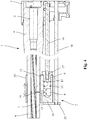
- FIG 3 Another embodiment of a gas drive according to the invention is shown.
- the basic structure of this version corresponds to the version of Figure 1 , so that mutually corresponding components are also provided with the same reference numerals and are not explained again in detail.
- a major difference compared to the execution of Figure 1 is that the gas take-off housing 12 is not fixedly arranged on the gun barrel 1. Rather, the gun barrel 1 and the gas take-off housing 12 are movable relative to one another in the axial direction.
- the gas take-off housing 12 contains a guide bush 23, via which the gas take-off housing 12 is displaceably guided on the front part 6 of the gun barrel 1 in the axial direction of the gun barrel 1 in accordance with the arrow.
- the closure actuating element 9 which is designed as a gas piston
- the gas pressure in the interior of the pressure chamber 8 also acts on the front part 10, which is designed as the front wall of the gas take-off housing 12, and exerts on the gas take-off housing 12 an axial force forward in the direction of the muzzle of the gun barrel 1.
- this force is absorbed by a support element 18 which is firmly connected to the closure housing 3.
- the support element 18 resting on the front of the gas take-off housing 12 is designed as a retaining web, which is arranged centrally to the lock actuating element 9, of a tubular or U-shaped forearm 24 connected to the lock housing 3.
- the gun barrel can e.g. expand or lengthen by heating in the axial direction without causing tension in relation to the gas take-off housing 12.
- the gas extraction bore 15 in the gas take-off housing 12 has a larger diameter than the bore 14 in the gun barrel 1, so that even with a slight displacement between the gun barrel 1 and the gas take-off housing 12, a connection remains between the barrel bore 7 and the pressure chamber 8.
- the gas take-off housing 12 is guided on the front part 6 of the gun barrel 1 via a guide bushing 23 so as to be longitudinally displaceable in the direction of the arrow.
- the closure actuating element 9 which is designed as a gas piston, is connected via a rearward-projecting, rod-shaped transmission element 16 to a closure actuating device, not shown here, for moving a closure body between a locking and unlocking position.
- the rod-shaped transmission element 16 is firmly connected at one end to the second part 9 and at the other end to the closure actuating device which is arranged in the closure housing 3 and is not shown here.
- the pressure chamber 8 is designed as a blind hole with an opening directed towards the rear in the direction of the start of the barrel.
- the support element 18 is designed as a holding rod arranged parallel to the gun barrel 1 and the transmission element 16 with a holder 25 resting on the front part 10.
- the rod-shaped support element 18 is fixedly connected at one end to the holder 25 and at the other end to the lock housing or system box 3 and is supported thereon.
- the axial forces acting on the gas take-off housing 12 due to the pressure within the pressure chamber 8 are conducted into the closure housing or the system box 3. Due to the displaceable arrangement of the gas take-off housing 12 on the gun barrel 1, the gun barrel 1 can move freely even under temperature-related expansions or changes in length, so that there is no tension and consequent deformations.
- closure actuating element 9 and pressure chamber 8 can also be interchanged.
- a closure actuating element 9 designed as a gas piston can be arranged on the guide bush 23 and the gas take-off housing 12 with the pressure chamber 8 or a gas cylinder belonging to the gas piston can be arranged on the transmission element 16. All gas drives arranged here under the gun barrel 1 can also be arranged above the gun barrel or at any point around the gun barrel 1.
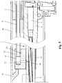
- the gas take-off housing 12 is arranged on the top of the gun barrel 1.
- the gas take-off housing 12 contains the gas take-off housing 12 a guide bush 23, via which the gas take-off housing 12 is guided on the front part 5 of the gun barrel 1 in the axial direction of the gun barrel 1 according to the arrow.
- the gun barrel 1 and the gas take-off housing 12 are thus movable relative to one another in the axial direction.
- the front part 10, which is designed here as a closed front wall of the gas take-off housing 12, is supported on the closure housing 3 by a support element 18 which lies against the front of the gas take-off housing 12 and is arranged centrally to the first part 9.
- the support element 18 is also part of a tubular or U-shaped forearm 24, which is connected to the closure housing 3.
- the closure actuating element 9 arranged at the rear end of the gas take-off housing 12 as seen in the firing direction not as a gas piston, but as a tube for transmitting the pressure in the pressure chamber 8 to the closure housing 3.
- a piston arranged in the closure housing 3 or another actuation mechanism for actuating a closure body or another closure actuation device can be moved via the pressure in the pressure chamber 8.
- the tubular closure actuating element 9 is connected to the gas take-off housing 12 via a cross pin 26.
- the tubular closure actuating element 9 can also be connected to the gas take-off housing 12 via a thread.
Landscapes
- Engineering & Computer Science (AREA)
- General Engineering & Computer Science (AREA)
- Toys (AREA)
- Actuator (AREA)
Description
- Die Erfindung betrifft einen Gasantrieb zum automatischen Nachladen einer Feuerwaffe nach dem Oberbegriff des Anspruchs 1.
- Bei Selbstlade-Feuerwaffen stellt das sogenannte Gasdrucklader-System ein weit verbreitetes Prinzip zum automatischen Nachladen dar. Hierbei wir ein Teil des bei der Abgabe eines Schusses entstehenden Gases der Treibladung über eine Bohrung in der Laufwandung abgezweigt und entweder direkt oder indirekt über einen Gaskolben auf einen Verschlussträger geleitet, um so den Nachladevorgang einzuleiten. Bei den Systemen mit einem Gaskolben ist an dem Waffenlauf in der Regel eine Gasabnahmeeinrichtung mit einem am Waffenlauf fest angeordneten Gasabnahmegehäuse vorgesehen. In einer innerhalb des Gasabnahmegehäuses angeordneten Druckkammer ist der Gaskolben axial verschiebbar geführt. Die Druckkammer steht über Gasentnahmebohrungen mit der Laufbohrung in Verbindung. Üblicherweise sind die in dem Gasabnahmegehäuse vorgesehenen Druckkammern an der einen Seite geschlossen. Dies führt jedoch dazu, dass die durch die eingeleiteten Gase erzeugten Druckkräfte auch auf die geschlossene vordere Wand des Gasabnahmegehäuses wirken und an dem fest mit dem Waffenlauf verbundenen Gasabnahmegehäuse zu einer nach vorne gerichteten Kraft führen. Diese Kraft kann an dem Waffenlauf ein Drehmoment bewirken, das zu Verformungen des Waffenlaufs und dadurch bedingten Beeinträchtigungen der Schusspräzision führen kann.
- Aus der
DE 10 2011 107 751 A1 ist ein gattungsgemäßer Gasantrieb einer Feuerwaffe bekannt. Bei diesem Gasantrieb ist an einem Waffenlauf eine Gasabnahmeeinrichtung angeordnet, die eine über einen Gasentnahmekanal mit einer Laufbohrung im Waffenlauf in Verbindung stehende Druckkammer enthält. Die Druckkammer wird an der in Schussrichtung gesehen hinteren Seite durch einen mittels des Drucks in der Druckkammer beweglichen Gaskolben und an ihrer vorderen Seite durch ein Vorderteil eines am Waffenlauf fest angeordneten Gasabnahmegehäuses begrenzt. Der axial bewegliche Gaskolben dient als Verschlussbetätigungselement, durch welches eine Verschlussbetätigungseinrichtung zur Bewegung eines Verschlusskörpers zwischen einer Verriegelungs- und Entriegelungsstellung für ein automatisches Nachladen der Feuerwaffe gesteuert werden kann. AuchUS2010/0251885 A1 undUS 2,920,536 offenbaren gattungsgemäße Gasantriebe. - Aufgabe der Erfindung ist es, einen Gasantrieb für eine Feuerwaffe zu schaffen, der eine verbesserte Schusspräzision ermöglicht.
- Diese Aufgabe wird durch einen Gasantrieb mit den Merkmalen des Anspruchs 1 gelöst. Zweckmäßige Ausgestaltungen und vorteilhafte Weiterbildungen der Erfindung sind in den Unteransprüchen angegeben.
- Bei dem erfindungsgemäßen Gasantrieb ist das die Druckkammer nach vorne begrenzende Vorderteil der Gasabnahmeeinrichtung über ein Stützelement am Verschlussgehäuse abgestützt. Außerdem ist der Waffenlauf axial beweglich relativ zu dem über das Stützelement am Verschlussgehäuse abgestützten Vorderteil. Dadurch ist die Gasabnahmeeinrichtung so von dem Waffenlauf entkoppelt, dass die durch den Druck innerhalb der Druckkammer wirkenden Axialkräfte nicht auf den Waffenlauf übertragen werden. Auf diese Weise können durch den Nachladevorgang erzeugte Schwingungen oder thermisch bedingte Verformungen und dadurch bedingte Beeinträchtigungen der Schusspräzision vermieden werden.
- In einer zweckmäßigen Ausführung kann das die Druckkammer in Schussrichtung nach vorne begrenzende Vorderteil der Gasabnahmeeinrichtung als Kolben ausgebildet sein, der in einer als Durchgangsöffnung ausgeführten Öffnung eines fest mit dem Waffenlauf verbundenen Gasabnahmegehäuses angeordnet und über ein stangenförmiges Stützelement fest mit dem Verschlussgehäuse verbunden ist. Bei dieser Ausführung übt der Gasdruck innerhalb der Druckkammer nach vorne keine Axialkraft auf das Gasabnahmegehäuse, sondern auf das durch das Stützelement am Verschlussgehäuse abgestützte kolbenförmige Vorderteil aus. Auf die Einheit aus Gasabnahmegehäuse und Waffenlauf wirkt damit auch kein Drehmoment, so dass der Waffenlauf durch den für den Ladevorgang verwendeten Gasdruck nicht verformt wird und die Schusspräzision verbessert werden kann.
- Das Verschlussbetätigungselement kann als ein innerhalb der Öffnung des Gasabnahmegehäuses axial verschiebbar geführter Gaskolben ausgebildet sein. Sowohl das vorzugsweise als Gaskolben ausgebildete Verschlussbetätigungselement als auch das kolbenförmige Vorderteil sind zweckmäßigerweise über Dichtungen oder Kolbenringe gegenüber dem Gasabnahmegehäuse abgedichtet.
- In einer besonders kompakten Bauweise kann das stangenförmige Stützelement koaxial zu dem als Gaskolben ausgebildeten Verschlussbetätigungselement und einem vom Verschlussbetätigungselement zum Verschlussgehäuse führenden Übertragungselement angeordnet sein. Das stangenförmige Stützelement kann z.B. durch ein zentrales Durchgangsloch in dem als Gaskolben ausgebildeten Verschlussbetätigungselement und in das als Hohlköper ausgeführte Übertragungselement ragen. Bei dieser koaxialen Anordnung ist das relativ zum Stützelement verschiebbare Verschlussbetätigungselement zweckmäßigerweise durch eine Dichtung radial gegenüber dem Stützelement abgedichtet. Das Stützelement kann aber auch parallel zum Übertragungselement angeordnet sein.
- In einer weiteren, vorteilhaften Ausführung kann das die Druckkammer in Schussrichtung nach vorne begrenzende Vorderteil der Gasabnahmeeinrichtung als geschlossene Vorderwand eines relativ zum Waffenlauf beweglichen Gasabnahmegehäuses ausgebildet sein. In einer besonders zweckmäßigen Ausgestaltung kann das Gasabnahmegehäuse über eine Führungsbuchse in Längsrichtung verschiebbar am Waffenlauf geführt sein. Die Führungsbuchse kann einteilig mit dem Gasabnahmegehäuse oder als gesondertes Bauteil ausgeführt sein.
- Das Stützelement kann bei dieser Ausführung als zentrisch zum Verschlussbetätigungselement angeordneter Haltesteg eines mit dem Verschlussgehäuse verbundenen Vorderschafts ausgeführt sein. Das Stützelement kann aber auch als parallel zum Waffenlauf angeordnete Haltestange mit einer an dem Vorderteil anliegenden Halterung oder auf andere geeignete Weise ausgebildet sein.
- Der zur Verbindung der Laufbohrung im Waffenlauf mit der Druckkammer der Gasabnahmeeinrichtung dienende Gasentnahmekanal kann in einer bevorzugten Ausführung eine von der Laufbohrung radial abzweigende Bohrung im Waffenlauf und eine mit der Bohrung fluchtende Gasentnahmebohrung im Gasabnahmegehäuse umfassen. Die Bohrung im Gasabnahmegehäuse weist einen größeren Durchmesser als die Gasabnahmebohrung im Waffenlauf auf, so dass auch bei einer durch Toleranzen oder Wärmedehnung bedingten Relativbewegung zwischen Waffenlauf und Gasabnahmegehäuse eine Verbindung zwischen der Laufbohrung und der Druckkammer besteht.
- Auch bei dieser Ausführung kann das Verschlussbetätigungselement als ein innerhalb einer Öffnung des Gasabnahmegehäuses axial verschiebbar geführter Gaskolben ausgebildet sein. Das Verschlussbetätigungselement kann aber auch als Rohr zur Weiterleitung des Drucks in der Druckkammer zum Verschlussgehäuse ausgeführt sein.
- Weitere Besonderheiten und Vorzüge der Erfindung ergeben sich aus der folgenden Beschreibung eines bevorzugten Ausführungsbeispiels anhand der Zeichnung. Es zeigen:
- Figur 1
- einen Gasantrieb einer Feuerwaffe nach dem Stand der Technik;
- Figur 2
- ein erstes Ausführungsbeispiel eines erfindungsgemäßen Gasantriebs;
- Figur 3
- ein zweites Ausführungsbeispiel eines erfindungsgemäßen Gasantriebs;
- Figur 4
- ein drittes Ausführungsbeispiel eines erfindungsgemäßen Gasantriebs und
- Figur 5
- ein viertes Ausführungsbeispiel eines erfindungsgemäßen Gasantriebs.
- In
Figur 1 ist ein Teil einer an sich bekannten Selbstlade-Feuerwaffe mit einem Waffenlauf 1 und einer an dem Waffenlauf 1 angeordneten Gasentnahmeeinrichtung 2 gezeigt. Der an einem Systemkasten bzw. Verschlussgehäuse 3 angeordnete Waffenlauf 1 weist einen im Durchmesser erweiterten hinteren Bereich 4 mit einem Patronenlager 5 und einen vorderen Bereich 6 mit einer Laufbohrung 7 auf. - Die im vorderen Bereich 6 des Waffenlaufs 1 angeordnete Gasentnahmeeinrichtung 2 enthält eine Druckkammer 8, die an ihrer in Schussrichtung gesehen hinteren Seite durch ein mittels des Drucks in der Druckkammer 8 in Richtung des Verschlussgehäuses 3 bewegliches Verschlussbetätigungselement 9 und an ihrer in Schussrichtung gesehen vorderen Seite durch ein Vorderteil 10 begrenzt wird. Bei der gezeigten Ausführung ist das Verschlussbetätigungselement 9 ein Gaskolben, der in einer als Sackloch ausgebildeten Öffnung 11 eines Gasabnahmegehäuses 12 parallel zum Waffenlauf 1 verschiebbar geführt ist. Das die Druckkammer 8 nach vorne begrenzende Vorderteil 10 wird bei der gezeigten Ausführung durch die geschlossene Vorderwand des Gasabnahmegehäuses 12 gebildet.
- Das hier als Gaskolben ausgeführte Verschlussbetätigungselement 9 ist innerhalb der Öffnung 11 des Gasabnahmegehäuses 12 über Dichtungen oder Kolbenringe 13 radial abgedichtet geführt. Die Druckkammer 8 steht mit der Laufbohrung 7 über einen Gasentnahmekanal in Verbindung. Dieser Gasentnahmekanal wird bei der gezeigten Ausführung durch eine von der Laufbohrung 7 radial abzweigende Bohrung 14 im Waffenlauf 1 und eine mit der Bohrung 14 fluchtende Gasentnahmebohrung 15 im Gasabnahmegehäuse 12 gebildet. Das als Gaskolben ausgeführte Verschlussbetätigungselement 9 ist über ein nach hinten ragendes, stangenförmiges Übertragungselement 16 mit einer hier nicht dargestellten Verschlussbetätigungseinrichtung zur Bewegung eines Verschlusskörpers zwischen einer Verriegelungs- und Entriegelungsstellung verbunden.
- Bei der in
Figur 1 gezeigten Ausführung ist das Übertragungselement 16 mit seinem in Schussrichtung gesehen vorderen Ende 17 mit dem als Gaskolben ausgebildeten Verschlussbetätigungselement 9 verbunden. Das andere Ende des Übertragungselements 16 ist mit der in dem Verschlussgehäuse bzw. Systemkasten 3 angeordneten - hier nicht dargestellten - Verschlussbetätigungseinrichtung verbunden. - Bei der Abgabe eines Schusses wird ein Teil des bei der Verbrennung der Treibladung entstehenden Gases abgezweigt und über die seitliche Öffnung 14 im Waffenlauf 1 sowie die Gasentnahmeöffhung 15 im Gasabnahmegehäuse 12 in die Druckkammer 8 geleitet. Durch das in die Druckkammer 8 geleitete Gas wird das als Gaskolben ausgebildete Verschlussbetätigungselement 9 in Schussrichtung gesehen nach hinten (in
Figur 1 nach rechts) gedrückt. Über das fest mit dem Verschlussbetätigungselement 9 verbundene Übertragungselement 16 kann eine im Verschlussgehäuse bzw. Systemkasten 3 angeordnete Verschlussbetätigungseinrichtung gesteuert werden. - Der Druck der in die Druckkammer 8 eingeleiteten Gase wirkt bei der bekannten - in
Figur 1 gezeigten - Ausführung auch auf das die Druckkammer 8 nach vorne begrenzende Vorderteil 10 des Gasabnahmegehäuses 12 und führt an dem fest mit dem Waffenlauf 1 verbundenen Gasabnahmegehäuse 12 zu einer nach vorne gerichteten Kraft, die wiederum am Waffenlauf 1 ein mit dem Pfeil dargestelltes Drehmoment M erzeugt. Ein derartiges Drehmoment führt jedoch zu Schwingungen oder Verformungen des Waffenlaufs 1 und dadurch bedingten Beeinträchtigungen der Schusspräzision. - In
Figur 2 ist ein erstes Ausführungsbeispiel eines erfindungsgemäßen Gasantriebs gezeigt. Auch bei dieser Ausführung weist der an einem Verschlussgehäuse 3 angeordnete Waffenlauf 1 einen im Durchmesser erweiterten hinteren Bereich 4 mit einem Patronenlager 5 und einen vorderen Bereich 6 mit einer Laufbohrung 7 auf. Die im vorderen Bereich 6 des Waffenlaufs 1 angeordnete Gasentnahmeeinrichtung 2 enthält eine parallel zum Waffenlauf 1 angeordnete Druckkammer 8, die auch hier an ihrer in Schussrichtung gesehen hinteren Seite durch ein mittels des Drucks in der Druckkammer 8 in Richtung des Verschlussgehäuses 3 bewegliches Verschlussbetätigungselement 9 und an ihrer in Schussrichtung gesehen vorderen Seite durch ein Vorderteil 10 begrenzt wird. - Das Verschlussbetätigungselement 9 der Gasentnahmeeinrichtung 2 ist ein Gaskolben, der in einer hier als Durchgangsöffnung ausgebildeten Öffnung 11 eines Gasabnahmegehäuses 12 parallel zum Waffenlauf 1 verschiebbar geführt ist. Im Unterschied zur Ausführung von
Figur 1 ist das Vorderteil 10 jedoch nicht als Vorderwand des Gasabnahmegehäuses 12 ausgebildet, sondern als Kolben, der in einer hier als Durchgangsöffnung ausgeführten Öffnung 11 des Gasabnahmegehäuses 12 angeordnet ist. Die von dem Vorderteil 10 und dem Verschlussbetätigungselement 9 begrenzte Druckkammer 8 steht mit der Laufbohrung 7 über einen Gasentnahmekanal mit einer von der Laufbohrung 7 radial abzweigenden Bohrung 14 im Waffenlauf 1 und einer mit der Bohrung 14 fluchtenden Gasentnahmebohrung 15 im Gasabnahmegehäuse 12 in Verbindung. - An der zum Verschlussgehäuse 3 gewandten hinteren Seite wird die Druckkammer 8 durch das als Gaskolben ausgeführte Verschlussbetätigungselement 9 begrenzt. Das als Gaskolben ausgebildete Verschlussbetätigungselement 9 ist über ein nach hinten ragendes, als Hohlkörper ausgebildetes Übertragungselement 16 mit einer hier nicht dargestellten Verschlussbetätigungseinrichtung zur Bewegung eines Verschlusskörpers zwischen einer Verriegelungs- und Entriegelungsstellung verbunden. Bei der gezeigten Ausführung ist das z.B. rohrförmige Übertragungselement 16 ein gesondertes Bauteil, das mit seinem in Schussrichtung gesehen vorderen Ende 17 fest mit als Gaskolben ausgeführten Verschlussbetätigungselement 9 verbunden ist. Das Übertragungselement 16 kann aber auch einteilig mit dem Verschlussbetätigungselement 9 ausgeführt sein.
- An der zur Mündung des Waffenlaufs 1 weisenden vorderen Seite wird die Druckkammer 8 durch das innerhalb der Öffnung 11 im Gasabnahmegehäuse 12 angeordnete Vorderteil 10 begrenzt. Das hier kolbenförmige Vorderteil 10 ist über ein stangenförmiges Stützelement 18 gegenüber dem Verschlussgehäuse 3 abgestützt. Sowohl das als Gaskolben ausgebildete Verschlussbetätigungselement 9 als auch das kolbenförmige Vorderteil 10 sind gegenüber der der Öffnung 11 im Gasabnahmegehäuse 12 über Dichtungen oder Kolbenringe 13 radial abgedichtet.
- Bei der in
Figur 2 gezeigten Ausführung ragt das hier stangenförmig ausgebildete Stützelement 18 durch ein zentrales Durchgangsloch 19 des als Gaskolben ausgebildeten Verschlussbetätigungselements 9. Das gegenüber dem Stützelement 18 verschiebbare Verschlussbetätigungselement 9 ist durch eine hier als Labyrinth-Dichtung ausgebildete Dichtung 20 gegenüber dem Stützelement 18 radial abgedichtet. Das stangenförmige Stützelement 18 ist mit seinem in Schussrichtung gesehen vorderen Ende 21 fest mit dem kolbenförmigen Vorderteil 10 und mit seinem hinteren Ende 22 fest mit dem Verschlussgehäuse 3 verbunden. Der nach hinten ragende Teil des stangenförmigen Stützelements 18 ist innerhalb des rohrförmigen Übertragungselements 16 angeordnet. Wenn bei dieser Ausführung das als Gaskolben ausgeführte Verschlussbetätigungselement 9 über das aus der Laufbohrung 7 abgezweigte Gas zur Betätigung der Verschlussbetätigungseinrichtung bewegt wird, übt der Gasdruck innerhalb der Druckkammer 8 nach vorne keine Axialkraft auf das Gasabnahmegehäuse 12, sondern auf das durch das Stützelement 18 am Verschlussgehäuse 3 abgestützte kolbenförmige Vorderteil 10 aus. Auf die Einheit aus Gasabnahmegehäuse 12 und Waffenlauf 1 wirkt damit auch kein Drehmoment, so dass der Waffenlauf 1 durch den für den Ladevorgang verwendeten Gasdruck nicht verformt wird und die Schusspräzision verbessert werden kann. - In
Figur 3 ist ein weiteres Ausführungsbeispiel eines erfindungsgemäßen Gasantriebs gezeigt. Diese Ausführung entspricht im Grundaufbau der Ausführung vonFigur 1 , so dass einander entsprechende Bauteile auch mit denselben Bezugszeichen versehen sind und nicht nochmals im Einzelnen erläutert werden. Ein wesentlicher Unterschied gegenüber der Ausführung vonFigur 1 besteht darin, dass das Gasabnahmegehäuse 12 nicht fest am Waffenlauf 1 angeordnet ist. Vielmehr sind der Waffenlauf 1 und das Gasabnahmegehäuse 12 in Axialrichtung relativ zueinander beweglich. Hierzu enthält das Gasabnahmegehäuse 12 eine Führungsbuchse 23, über die das Gasabnahmegehäuse 12 auf dem vorderen Teil 6 des Waffenlaufs 1 in Axialrichtung des Waffenlaufs 1 entsprechend dem Pfeil verschiebbar geführt ist. - Wenn bei dieser Ausführung das als Gaskolben ausgeführte Verschlussbetätigungselement 9 über das aus der Laufbohrung 7 abgezweigte Gas zur Betätigung der Verschlussbetätigungseinrichtung bewegt wird, wirkt der Gasdruck im Inneren der Druckkammer 8 auch auf das als Vorderwand des Gasabnahmegehäuses 12 ausgebildete Vorderteil 10 und übt auf das Gasabnahmegehäuse 12 eine Axialkraft nach vorne in Richtung der Mündung des Waffenlaufs 1 aus. Allerdings wird diese Kraft durch ein fest mit dem Verschlussgehäuse 3 verbundenes Stützelement 18 aufgenommen. Bei der in
Figur 3 gezeigten Ausführung ist das an der Vorderseite des Gasabnahmegehäuses 12 anliegende Stützelement 18 als zentrisch zum Verschlussbetätigungselement 9 angeordneter Haltesteg eines mit dem Verschlussgehäuse 3 verbundenen rohr- oder U-förmigen Vorderschafts 24 ausgeführt. - Da bei dieser Ausführung das Gasabnahmegehäuse 12 und der Waffenlauf 1 axial gegeneinander beweglich sind, kann sich der Waffenlauf z.B. durch Erwärmung in Axialrichtung ausdehnen bzw. längen, ohne dass es dadurch zu Verspannungen gegenüber dem Gasabnahmegehäuse 12 kommt. Die Gasentnahmebohrung 15 im Gasabnahmegehäuse 12 weist einen größeren Durchmesser als die Bohrung 14 im Waffenlauf 1 auf, so dass selbst bei einer geringen Verschiebung zwischen Waffenlauf 1 und Gasabnahmegehäuse 12 eine Verbindung zwischen der Laufbohrung 7 und der Druckkammer 8 bleibt.
- Die in
Figur 4 dargestellte weitere Ausführung entspricht im Wesentlichen dem Ausführungsbeispiel vonFigur 3 . Auch hier ist das Gasabnahmegehäuse 12 auf dem vorderen Teil 6 des Waffenlaufs 1 über eine Führungsbuchse 23 in Pfeilrichtung längsverschiebbar geführt. Wie bei der Ausführung vonFigur 3 ist das als Gaskolben ausgeführte Verschlussbetätigungselement 9 über ein nach hinten ragendes, stangenförmiges Übertragungselement 16 mit einer hier nicht dargestellten Verschlussbetätigungseinrichtung zur Bewegung eines Verschlusskörpers zwischen einer Verriegelungs- und Entriegelungsstellung verbunden. Bei dieser Ausführung ist das stangenförmige Übertragungselement 16 an einen Ende fest mit dem zweiten Teil 9 und mit dem anderen Ende mit der in dem Verschlussgehäuse 3 angeordneten - hier nicht dargestellten - Verschlussbetätigungseinrichtung verbunden. Die Druckkammer 8 ist als Sackloch mit einer nach hinten in Richtung des Laufanfangs gerichteten Öffnung ausgeführt. - Im Unterschied zu der Ausführung von
Figur 3 ist das Stützelement 18 als parallel zum Waffenlauf 1 und zum Übertragungselement 16 angeordnete Haltestange mit einer am Vorderteil 10 anliegenden Halterung 25 ausgeführt. Das stangenförmige Stützelement 18 ist an dem einen Ende fest mit der Halterung 25 und an dem anderen Ende fest mit dem Verschlussgehäuse bzw. Systemkasten 3 verbunden und an diesem abgestützt. Durch das stangenförmige Stützelement 18 werden die durch den Druck innerhalb der Druckkammer 8 auf das Gasabnahmegehäuse 12 wirkenden Axialkräfte in das Verschlussgehäuse bzw. den Systemkasten 3 geleitet. Durch die verschiebbare Anordnung des Gasabnahmegehäuses 12 am Waffenlauf 1 kann sich der Waffenlauf 1 auch bei temperaturbedingten Dehnungen oder Längenänderungen frei bewegen, so dass es zu keinen Verspannungen und dadurch bedingten Verformungen kommt. - Bei den Gasantrieben gemäß der
Figuren 3 und4 können Verschlussbetätigungselement 9 und Druckkammer 8 auch vertauscht sein. So kann an der Führungsbuchse 23 anstelle des Gasabnahmegehäuses 12 mit der Druckkammer 8 auch ein als Gaskolben ausgeführtes Verschlussbetätigungselement 9 und am Übertragungselement 16 das Gasabnahmegehäuse 12 mit der Druckkammer 8 bzw. ein zum Gaskolben gehörender Gaszylinder angeordnet sein. Alle hier unter dem Waffenlauf 1 angeordneten Gasantriebe können auch über dem Waffenlauf oder an beliebigen Stellen um den Waffenlauf 1 herum angeordnet sein. - Bei dem in
Figur 5 dargestellten Ausführungsbeispiel ist das Gasabnahmegehäuse 12 auf der Oberseite des Waffenlaufs 1 angeordnet. Wie bei der Ausführung vonFigur 3 enthält das Gasabnahmegehäuse 12 eine Führungsbuchse 23, über die das Gasabnahmegehäuse 12 auf dem vorderen Teil 5 des Waffenlaufs 1 in Axialrichtung des Waffenlaufs 1 entsprechend dem Pfeil verschiebbar geführt ist. Der Waffenlauf 1 und das Gasabnahmegehäuse 12 sind somit in Axialrichtung relativ zueinander beweglich. Das hier als geschlossene Vorderwand des Gasabnahmegehäuses 12 ausgebildete Vorderteil 10 wird durch ein an der Vorderseite des Gasabnahmegehäuses 12 anliegendes und zentrisch zum ersten Teil 9 angeordnetes Stützelement 18 an dem Verschlussgehäuse 3 abgestützt. Das Stützelement 18 ist auch hier Teil eines rohr- oder U-förmigen Vorderschafts 24, der mit dem Verschlussgehäuse 3 verbunden ist. - Im Unterschied zur Ausführung von
Figur 3 ist das an dem in Schussrichtung gesehen hinteren Ende des Gasabnahmegehäuses 12 angeordnete Verschlussbetätigungselement 9 nicht als Gaskolben, sondern als Rohr zur Weiterleitung des Drucks in der Druckkammer 8 zum Verschlussgehäuse 3 ausgeführt. Dadurch kann über den Druck in der Druckkammer 8 z.B. ein im Verschlussgehäuse 3 angeordneter Kolben oder ein anderer Betätigungsmechanismus zur Betätigung eines Verschlusskörpers oder einer anderen Verschlussbetätigungseinrichtung bewegt werden. Bei der gezeigten Ausführung ist das rohrförmige Verschlussbetätigungselement 9 über einen Querstift 26 mit dem Gasabnahmegehäuse 12 verbunden. Das rohrförmige Verschlussbetätigungselement 9 kann aber auch über ein Gewinde mit dem Gasabnahmegehäuse 12 verbunden sein. -
- 1
- Waffenlauf
- 2
- Gasabnahmeeinrichtung
- 3
- Verschlussgehäuse
- 4
- Hinterer Bereich des Waffenlaufs
- 5
- Patronenlager
- 6
- Vorderer Bereich des Waffenlaufs
- 7
- Laufbohrung
- 8
- Druckkammer
- 9
- Verschlussbetätigungselement
- 10
- Vorderteil
- 11
- Öffnung
- 12
- Gasabnahmegehäuse
- 13
- Kolbenring
- 14
- Bohrung
- 15
- Gasentnahmebohrung
- 16
- Übertragungselement
- 17
- Vorderes Ende des Übertragungselements
- 18
- Stützelement
- 19
- Durchgangsloch
- 20
- Dichtung
- 21
- Vorderes Ende des Stützelements
- 22
- Hinteres Ende des Stützelements
- 23
- Führungsbuchse
- 24
- Vorderschaft
- 25
- Halterung
- 26
- Querstift
Claims (15)
- Gasantrieb für eine Feuerwaffe mit einem an einem Verschlussgehäuse (3) angeordneten Waffenlauf (1) und einer am Waffenlauf (1) angeordneten Gasabnahmeeinrichtung (2) mit einer über einen Gasentnahmekanal (14, 15) mit einer Laufbohrung (7) im Waffenlauf (1) in Verbindung stehenden Druckkammer (8), die an einer in Schussrichtung gesehen hinteren Seite durch ein mittels des Drucks in der Druckkammer (8) in Richtung des Verschlussgehäuses (3) bewegliches oder den Druck in der Druckkammer (8) zum Verschlussgehäuse (3) leitendes Verschlussbetätigungselement (9) und an ihrer in Schussrichtung gesehen vorderen Seite durch ein Vorderteil (10) begrenzt wird, dadurch gekennzeichnet, dass der Waffenlauf (1) axial beweglich relativ zu dem über ein Stützelement (18) am Verschlussgehäuse (3) abgestützten Vorderteil (10) der Gasabnahmeeinrichtung (2) ist.
- Gasantrieb nach Anspruch 1, dadurch gekennzeichnet, dass das die Druckkammer (8) in Schussrichtung nach vorne begrenzende Vorderteil (10) der Gasabnahmeeinrichtung (2) als Kolben ausgebildet ist, der in einer als Durchgangsöffnung ausgeführten Öffnung (11) eines fest mit dem Waffenlauf (1) verbundenen Gasabnahmegehäuses (12) angeordnet und über ein stangenförmiges Stützelement (18) fest mit dem Verschlussgehäuse (3) verbunden ist.
- Gasantrieb nach Anspruch 2, dadurch gekennzeichnet, dass das Verschlussbetätigungselement (9) als ein innerhalb der Öffnung (11) des Gasabnahmegehäuses (12) axial verschiebbar geführter Gaskolben ausgebildet ist.
- Gasantrieb nach Anspruch 3, dadurch gekennzeichnet, dass das als Gaskolben ausgebildete Verschlussbetätigungselement (9) und das als Kolben ausgeführte Vorderteil (10) über Dichtungen oder Kolbenringe (13) gegenüber dem Gasabnahmegehäuse (12) abgedichtet sind.
- Gasantrieb nach Anspruch 3 oder 4, dadurch gekennzeichnet, dass das stangenförmige Stützelement (18) koaxial zu dem als Gaskolben ausgebildeten Verschlussbetätigungselement (9) und einem vom Verschlussbetätigungselement (9) zum Verschlussgehäuse führenden Übertragungselement (16) angeordnet ist.
- Gasantrieb nach Anspruch 5, dadurch gekennzeichnet, dass das stangenförmige Stützelement (18) durch ein zentrales Durchgangsloch (19) in dem als Gaskolben ausgebildeten Verschlussbetätigungselement (9) und in das als Hohlkörper ausgebildete Übertragungselement (16) ragt.
- Gasantrieb nach Anspruch 6, dadurch gekennzeichnet, dass das Verschlussbetätigungselement (9) durch eine Dichtung (20) radial gegenüber dem Stützelement (18) abgedichtet ist.
- Gasantrieb nach Anspruch 1, dadurch gekennzeichnet, dass das die Druckkammer (8) in Schussrichtung nach vorne begrenzende Vorderteil (10) der Gasabnahmeeinrichtung (2) als Vorderwand eines relativ zum Waffenlauf (1) beweglichen Gasabnahmegehäuses (12) ausgebildet ist.
- Gasantrieb nach Anspruch 8, dadurch gekennzeichnet, dass das Gasabnahmegehäuse (12) über eine Führungsbuchse (23) in Längsrichtung verschiebbar am Waffenlauf (1) geführt ist.
- Gasantrieb nach Anspruch 8 oder 9, dadurch gekennzeichnet, dass das Stützelement (18) als zentrisch zum Verschlussbetätigungselement (9) angeordneter Haltesteg eines mit dem Verschlussgehäuse (3) verbundenen Vorderschafts (24) ausgeführt ist.
- Gasantrieb nach Anspruch 8 oder 9, dadurch gekennzeichnet, dass das Stützelement (18) als parallel zum Waffenlauf (1) angeordnete Haltestange mit einer an dem Vorderteil (10) anliegenden Halterung (25) ausgebildet ist.
- Gasantrieb nach einem der Ansprüche 8 bis 11, dadurch gekennzeichnet, dass der Gasentnahmekanal (14, 15) eine von der Laufbohrung (7) radial abzweigende Bohrung (14) im Waffenlauf (1) und eine mit der Bohrung (14) fluchtende Gasentnahmebohrung (15) im Gasabnahmegehäuse (12) umfasst.
- Gasantrieb nach Anspruch 12, dadurch gekennzeichnet, dass die Gasentnahmebohrung (15) im Gasabnahmegehäuse (12) einen größeren Durchmesser als die Bohrung (14) im Gewehrlauf (1) aufweist.
- Gasantrieb nach einem der Ansprüche 8 bis 13, dadurch gekennzeichnet, dass das Verschlussbetätigungselement (9) als ein innerhalb einer Öffnung (11) des Gasabnahmegehäuses (12) axial verschiebbar geführter Gaskolben ausgebildet ist.
- Gasantrieb nach einem der Ansprüche 8 bis 13, dadurch gekennzeichnet, dass das Verschlussbetätigungselement (9) als Rohr zur Weiterleitung des Drucks in der Druckkammer (8) zum Verschlussgehäuse (3) ausgeführt ist.
Applications Claiming Priority (1)
| Application Number | Priority Date | Filing Date | Title |
|---|---|---|---|
| DE102017125056.5A DE102017125056A1 (de) | 2017-10-26 | 2017-10-26 | Momentfreier Gasantrieb für eine Feuerwaffe |
Publications (2)
| Publication Number | Publication Date |
|---|---|
| EP3477240A1 EP3477240A1 (de) | 2019-05-01 |
| EP3477240B1 true EP3477240B1 (de) | 2020-05-13 |
Family
ID=63965331
Family Applications (1)
| Application Number | Title | Priority Date | Filing Date |
|---|---|---|---|
| EP18201940.6A Active EP3477240B1 (de) | 2017-10-26 | 2018-10-23 | Momentfreier gasantrieb für eine feuerwaffe |
Country Status (2)
| Country | Link |
|---|---|
| EP (1) | EP3477240B1 (de) |
| DE (1) | DE102017125056A1 (de) |
Families Citing this family (1)
| Publication number | Priority date | Publication date | Assignee | Title |
|---|---|---|---|---|
| WO2021222950A1 (de) * | 2020-05-08 | 2021-11-11 | Descom-Engineering GmbH | Gasdruckgesteuertes verschlusssystem fuer eine feuerwaffe |
Family Cites Families (8)
| Publication number | Priority date | Publication date | Assignee | Title |
|---|---|---|---|---|
| US2800059A (en) * | 1953-06-05 | 1957-07-23 | John M Miller | Gas operated rifle |
| BE541451A (de) * | 1954-10-16 | |||
| BE758832A (fr) * | 1969-11-13 | 1971-04-16 | Oerlikon Buehrle Ag | Arme a feu automatique |
| DE19739451A1 (de) * | 1997-09-09 | 1999-03-11 | Mehmet Celik | Infanteriegewehr |
| US8250964B2 (en) * | 2007-08-29 | 2012-08-28 | Ra Brands, L.L.C. | Gas system for firearms |
| DE102011107751A1 (de) | 2011-07-15 | 2013-01-17 | Schmeisser Gmbh | Gasabnahmeanordnung für einen Lauf einer Waffe |
| US8528458B2 (en) * | 2011-07-27 | 2013-09-10 | Bernard T. Windauer | Pressure-regulating gas block |
| DE202015001384U1 (de) * | 2015-02-20 | 2015-03-23 | Waffen-Albert Gmbh | Handfeuerwaffe mit Gaskolbeneinrichtung |
-
2017
- 2017-10-26 DE DE102017125056.5A patent/DE102017125056A1/de not_active Withdrawn
-
2018
- 2018-10-23 EP EP18201940.6A patent/EP3477240B1/de active Active
Non-Patent Citations (1)
| Title |
|---|
| None * |
Also Published As
| Publication number | Publication date |
|---|---|
| DE102017125056A1 (de) | 2019-05-02 |
| EP3477240A1 (de) | 2019-05-01 |
Similar Documents
| Publication | Publication Date | Title |
|---|---|---|
| EP2867607B1 (de) | Schalldämpfer für eine handfeuerwaffe | |
| DE69211563T2 (de) | Waffensystem mit einer daempfvorrichtung | |
| DE3728533C2 (de) | ||
| EP1963772B1 (de) | Gasabnahmeanordnung und lauf bzw. waffe mit einer gasabnahmeanordnung | |
| EP3372942B1 (de) | Verriegelbare selbstlade-handfeuerwaffe | |
| EP1371930B1 (de) | Rohrwaffe | |
| WO2007131781A1 (de) | WAFFENVERSCHLUßSYSTEM | |
| EP2923169B1 (de) | Rohrwaffe mit einem massenverriegelbaren verschlusssystem | |
| DE1578372C3 (de) | Steuervorrichtung zur Entriegelung des Verschlusses einer Gasdrucklader-Feuerwaffe | |
| DE2944859C2 (de) | Vor- und Rücklaufeinrichtung für eine Feuerwaffe | |
| EP0220370B1 (de) | Rohrbremse | |
| EP3477240A1 (de) | Momentfreier gasantrieb für eine feuerwaffe | |
| DE69215510T2 (de) | Schlagzündvorrichtung für mörsern oder ähnlichen geschützen | |
| EP4230950B1 (de) | Verschluss für ein geradezug-repetiergewehr | |
| DE202017106479U1 (de) | Momentfreier Gasantrieb für eine Feuerwaffe | |
| EP2561304B1 (de) | Rohrwaffe mit verschlusskeilschliessmechanismus | |
| EP3607261B1 (de) | Vorrichtung zum laden einer rohrwaffe mit munitionskörpern | |
| DE3434754A1 (de) | Luftkompressionssystem fuer druckluftschusswaffen | |
| AT522975B1 (de) | Gasdruckgesteuertes Verschlusssystem für eine Feuerwaffe | |
| DE102020106078B3 (de) | Gasdruckladegewehr | |
| DE202015001384U1 (de) | Handfeuerwaffe mit Gaskolbeneinrichtung | |
| DE102004034756A1 (de) | Artilleriegeschoss | |
| WO2021222950A1 (de) | Gasdruckgesteuertes verschlusssystem fuer eine feuerwaffe | |
| EP1052470A2 (de) | Aufsatzvorrichtung für die Gasabnahme einer automatischen Waffe | |
| DE4009050A1 (de) | Automatische rohrwaffe |
Legal Events
| Date | Code | Title | Description |
|---|---|---|---|
| PUAI | Public reference made under article 153(3) epc to a published international application that has entered the european phase |
Free format text: ORIGINAL CODE: 0009012 |
|
| STAA | Information on the status of an ep patent application or granted ep patent |
Free format text: STATUS: THE APPLICATION HAS BEEN PUBLISHED |
|
| AK | Designated contracting states |
Kind code of ref document: A1 Designated state(s): AL AT BE BG CH CY CZ DE DK EE ES FI FR GB GR HR HU IE IS IT LI LT LU LV MC MK MT NL NO PL PT RO RS SE SI SK SM TR |
|
| AX | Request for extension of the european patent |
Extension state: BA ME |
|
| STAA | Information on the status of an ep patent application or granted ep patent |
Free format text: STATUS: REQUEST FOR EXAMINATION WAS MADE |
|
| 17P | Request for examination filed |
Effective date: 20191104 |
|
| GRAP | Despatch of communication of intention to grant a patent |
Free format text: ORIGINAL CODE: EPIDOSNIGR1 |
|
| RBV | Designated contracting states (corrected) |
Designated state(s): AL AT BE BG CH CY CZ DE DK EE ES FI FR GB GR HR HU IE IS IT LI LT LU LV MC MK MT NL NO PL PT RO RS SE SI SK SM TR |
|
| STAA | Information on the status of an ep patent application or granted ep patent |
Free format text: STATUS: GRANT OF PATENT IS INTENDED |
|
| INTG | Intention to grant announced |
Effective date: 20191212 |
|
| GRAS | Grant fee paid |
Free format text: ORIGINAL CODE: EPIDOSNIGR3 |
|
| GRAA | (expected) grant |
Free format text: ORIGINAL CODE: 0009210 |
|
| STAA | Information on the status of an ep patent application or granted ep patent |
Free format text: STATUS: THE PATENT HAS BEEN GRANTED |
|
| AK | Designated contracting states |
Kind code of ref document: B1 Designated state(s): AL AT BE BG CH CY CZ DE DK EE ES FI FR GB GR HR HU IE IS IT LI LT LU LV MC MK MT NL NO PL PT RO RS SE SI SK SM TR |
|
| REG | Reference to a national code |
Ref country code: GB Ref legal event code: FG4D Free format text: NOT ENGLISH |
|
| REG | Reference to a national code |
Ref country code: CH Ref legal event code: EP |
|
| REG | Reference to a national code |
Ref country code: CH Ref legal event code: NV Representative=s name: LUCHS AND PARTNER AG PATENTANWAELTE, CH |
|
| REG | Reference to a national code |
Ref country code: DE Ref legal event code: R096 Ref document number: 502018001435 Country of ref document: DE |
|
| REG | Reference to a national code |
Ref country code: AT Ref legal event code: REF Ref document number: 1270848 Country of ref document: AT Kind code of ref document: T Effective date: 20200615 |
|
| REG | Reference to a national code |
Ref country code: LT Ref legal event code: MG4D |
|
| REG | Reference to a national code |
Ref country code: NL Ref legal event code: MP Effective date: 20200513 |
|
| PG25 | Lapsed in a contracting state [announced via postgrant information from national office to epo] |
Ref country code: GR Free format text: LAPSE BECAUSE OF FAILURE TO SUBMIT A TRANSLATION OF THE DESCRIPTION OR TO PAY THE FEE WITHIN THE PRESCRIBED TIME-LIMIT Effective date: 20200814 Ref country code: NO Free format text: LAPSE BECAUSE OF FAILURE TO SUBMIT A TRANSLATION OF THE DESCRIPTION OR TO PAY THE FEE WITHIN THE PRESCRIBED TIME-LIMIT Effective date: 20200813 Ref country code: FI Free format text: LAPSE BECAUSE OF FAILURE TO SUBMIT A TRANSLATION OF THE DESCRIPTION OR TO PAY THE FEE WITHIN THE PRESCRIBED TIME-LIMIT Effective date: 20200513 Ref country code: IS Free format text: LAPSE BECAUSE OF FAILURE TO SUBMIT A TRANSLATION OF THE DESCRIPTION OR TO PAY THE FEE WITHIN THE PRESCRIBED TIME-LIMIT Effective date: 20200913 Ref country code: PT Free format text: LAPSE BECAUSE OF FAILURE TO SUBMIT A TRANSLATION OF THE DESCRIPTION OR TO PAY THE FEE WITHIN THE PRESCRIBED TIME-LIMIT Effective date: 20200914 Ref country code: SE Free format text: LAPSE BECAUSE OF FAILURE TO SUBMIT A TRANSLATION OF THE DESCRIPTION OR TO PAY THE FEE WITHIN THE PRESCRIBED TIME-LIMIT Effective date: 20200513 Ref country code: LT Free format text: LAPSE BECAUSE OF FAILURE TO SUBMIT A TRANSLATION OF THE DESCRIPTION OR TO PAY THE FEE WITHIN THE PRESCRIBED TIME-LIMIT Effective date: 20200513 |
|
| PG25 | Lapsed in a contracting state [announced via postgrant information from national office to epo] |
Ref country code: RS Free format text: LAPSE BECAUSE OF FAILURE TO SUBMIT A TRANSLATION OF THE DESCRIPTION OR TO PAY THE FEE WITHIN THE PRESCRIBED TIME-LIMIT Effective date: 20200513 Ref country code: HR Free format text: LAPSE BECAUSE OF FAILURE TO SUBMIT A TRANSLATION OF THE DESCRIPTION OR TO PAY THE FEE WITHIN THE PRESCRIBED TIME-LIMIT Effective date: 20200513 Ref country code: LV Free format text: LAPSE BECAUSE OF FAILURE TO SUBMIT A TRANSLATION OF THE DESCRIPTION OR TO PAY THE FEE WITHIN THE PRESCRIBED TIME-LIMIT Effective date: 20200513 Ref country code: BG Free format text: LAPSE BECAUSE OF FAILURE TO SUBMIT A TRANSLATION OF THE DESCRIPTION OR TO PAY THE FEE WITHIN THE PRESCRIBED TIME-LIMIT Effective date: 20200813 |
|
| PG25 | Lapsed in a contracting state [announced via postgrant information from national office to epo] |
Ref country code: NL Free format text: LAPSE BECAUSE OF FAILURE TO SUBMIT A TRANSLATION OF THE DESCRIPTION OR TO PAY THE FEE WITHIN THE PRESCRIBED TIME-LIMIT Effective date: 20200513 Ref country code: AL Free format text: LAPSE BECAUSE OF FAILURE TO SUBMIT A TRANSLATION OF THE DESCRIPTION OR TO PAY THE FEE WITHIN THE PRESCRIBED TIME-LIMIT Effective date: 20200513 |
|
| PG25 | Lapsed in a contracting state [announced via postgrant information from national office to epo] |
Ref country code: DK Free format text: LAPSE BECAUSE OF FAILURE TO SUBMIT A TRANSLATION OF THE DESCRIPTION OR TO PAY THE FEE WITHIN THE PRESCRIBED TIME-LIMIT Effective date: 20200513 Ref country code: IT Free format text: LAPSE BECAUSE OF FAILURE TO SUBMIT A TRANSLATION OF THE DESCRIPTION OR TO PAY THE FEE WITHIN THE PRESCRIBED TIME-LIMIT Effective date: 20200513 Ref country code: EE Free format text: LAPSE BECAUSE OF FAILURE TO SUBMIT A TRANSLATION OF THE DESCRIPTION OR TO PAY THE FEE WITHIN THE PRESCRIBED TIME-LIMIT Effective date: 20200513 Ref country code: SM Free format text: LAPSE BECAUSE OF FAILURE TO SUBMIT A TRANSLATION OF THE DESCRIPTION OR TO PAY THE FEE WITHIN THE PRESCRIBED TIME-LIMIT Effective date: 20200513 Ref country code: CZ Free format text: LAPSE BECAUSE OF FAILURE TO SUBMIT A TRANSLATION OF THE DESCRIPTION OR TO PAY THE FEE WITHIN THE PRESCRIBED TIME-LIMIT Effective date: 20200513 Ref country code: RO Free format text: LAPSE BECAUSE OF FAILURE TO SUBMIT A TRANSLATION OF THE DESCRIPTION OR TO PAY THE FEE WITHIN THE PRESCRIBED TIME-LIMIT Effective date: 20200513 Ref country code: ES Free format text: LAPSE BECAUSE OF FAILURE TO SUBMIT A TRANSLATION OF THE DESCRIPTION OR TO PAY THE FEE WITHIN THE PRESCRIBED TIME-LIMIT Effective date: 20200513 |
|
| REG | Reference to a national code |
Ref country code: DE Ref legal event code: R097 Ref document number: 502018001435 Country of ref document: DE |
|
| PG25 | Lapsed in a contracting state [announced via postgrant information from national office to epo] |
Ref country code: PL Free format text: LAPSE BECAUSE OF FAILURE TO SUBMIT A TRANSLATION OF THE DESCRIPTION OR TO PAY THE FEE WITHIN THE PRESCRIBED TIME-LIMIT Effective date: 20200513 Ref country code: SK Free format text: LAPSE BECAUSE OF FAILURE TO SUBMIT A TRANSLATION OF THE DESCRIPTION OR TO PAY THE FEE WITHIN THE PRESCRIBED TIME-LIMIT Effective date: 20200513 |
|
| PLBE | No opposition filed within time limit |
Free format text: ORIGINAL CODE: 0009261 |
|
| STAA | Information on the status of an ep patent application or granted ep patent |
Free format text: STATUS: NO OPPOSITION FILED WITHIN TIME LIMIT |
|
| 26N | No opposition filed |
Effective date: 20210216 |
|
| PG25 | Lapsed in a contracting state [announced via postgrant information from national office to epo] |
Ref country code: SI Free format text: LAPSE BECAUSE OF FAILURE TO SUBMIT A TRANSLATION OF THE DESCRIPTION OR TO PAY THE FEE WITHIN THE PRESCRIBED TIME-LIMIT Effective date: 20200513 |
|
| PG25 | Lapsed in a contracting state [announced via postgrant information from national office to epo] |
Ref country code: LU Free format text: LAPSE BECAUSE OF NON-PAYMENT OF DUE FEES Effective date: 20201023 Ref country code: MC Free format text: LAPSE BECAUSE OF FAILURE TO SUBMIT A TRANSLATION OF THE DESCRIPTION OR TO PAY THE FEE WITHIN THE PRESCRIBED TIME-LIMIT Effective date: 20200513 |
|
| REG | Reference to a national code |
Ref country code: BE Ref legal event code: MM Effective date: 20201031 |
|
| PG25 | Lapsed in a contracting state [announced via postgrant information from national office to epo] |
Ref country code: FR Free format text: LAPSE BECAUSE OF NON-PAYMENT OF DUE FEES Effective date: 20201031 |
|
| PG25 | Lapsed in a contracting state [announced via postgrant information from national office to epo] |
Ref country code: BE Free format text: LAPSE BECAUSE OF NON-PAYMENT OF DUE FEES Effective date: 20201031 |
|
| PG25 | Lapsed in a contracting state [announced via postgrant information from national office to epo] |
Ref country code: IE Free format text: LAPSE BECAUSE OF NON-PAYMENT OF DUE FEES Effective date: 20201023 |
|
| PG25 | Lapsed in a contracting state [announced via postgrant information from national office to epo] |
Ref country code: TR Free format text: LAPSE BECAUSE OF FAILURE TO SUBMIT A TRANSLATION OF THE DESCRIPTION OR TO PAY THE FEE WITHIN THE PRESCRIBED TIME-LIMIT Effective date: 20200513 Ref country code: MT Free format text: LAPSE BECAUSE OF FAILURE TO SUBMIT A TRANSLATION OF THE DESCRIPTION OR TO PAY THE FEE WITHIN THE PRESCRIBED TIME-LIMIT Effective date: 20200513 Ref country code: CY Free format text: LAPSE BECAUSE OF FAILURE TO SUBMIT A TRANSLATION OF THE DESCRIPTION OR TO PAY THE FEE WITHIN THE PRESCRIBED TIME-LIMIT Effective date: 20200513 |
|
| PG25 | Lapsed in a contracting state [announced via postgrant information from national office to epo] |
Ref country code: MK Free format text: LAPSE BECAUSE OF FAILURE TO SUBMIT A TRANSLATION OF THE DESCRIPTION OR TO PAY THE FEE WITHIN THE PRESCRIBED TIME-LIMIT Effective date: 20200513 |
|
| GBPC | Gb: european patent ceased through non-payment of renewal fee |
Effective date: 20221023 |
|
| PG25 | Lapsed in a contracting state [announced via postgrant information from national office to epo] |
Ref country code: GB Free format text: LAPSE BECAUSE OF NON-PAYMENT OF DUE FEES Effective date: 20221023 |
|
| REG | Reference to a national code |
Ref country code: CH Ref legal event code: U11 Free format text: ST27 STATUS EVENT CODE: U-0-0-U10-U11 (AS PROVIDED BY THE NATIONAL OFFICE) Effective date: 20251101 |
|
| PGFP | Annual fee paid to national office [announced via postgrant information from national office to epo] |
Ref country code: DE Payment date: 20251106 Year of fee payment: 8 |
|
| PGFP | Annual fee paid to national office [announced via postgrant information from national office to epo] |
Ref country code: AT Payment date: 20251021 Year of fee payment: 8 |
|
| PGFP | Annual fee paid to national office [announced via postgrant information from national office to epo] |
Ref country code: CH Payment date: 20251101 Year of fee payment: 8 |