EP3458265B1 - Vorrichtung zur oberflächenbehandlung eines substrats mit einem metallischen transportband - Google Patents
Vorrichtung zur oberflächenbehandlung eines substrats mit einem metallischen transportband Download PDFInfo
- Publication number
- EP3458265B1 EP3458265B1 EP17716837.4A EP17716837A EP3458265B1 EP 3458265 B1 EP3458265 B1 EP 3458265B1 EP 17716837 A EP17716837 A EP 17716837A EP 3458265 B1 EP3458265 B1 EP 3458265B1
- Authority
- EP
- European Patent Office
- Prior art keywords
- conveyor belt
- corona
- range
- substrate
- belt
- Prior art date
- Legal status (The legal status is an assumption and is not a legal conclusion. Google has not performed a legal analysis and makes no representation as to the accuracy of the status listed.)
- Active
Links
Images


Classifications
-
- B—PERFORMING OPERATIONS; TRANSPORTING
- B05—SPRAYING OR ATOMISING IN GENERAL; APPLYING FLUENT MATERIALS TO SURFACES, IN GENERAL
- B05D—PROCESSES FOR APPLYING FLUENT MATERIALS TO SURFACES, IN GENERAL
- B05D1/00—Processes for applying liquids or other fluent materials
- B05D1/28—Processes for applying liquids or other fluent materials performed by transfer from the surfaces of elements carrying the liquid or other fluent material, e.g. brushes, pads, rollers
-
- B—PERFORMING OPERATIONS; TRANSPORTING
- B05—SPRAYING OR ATOMISING IN GENERAL; APPLYING FLUENT MATERIALS TO SURFACES, IN GENERAL
- B05D—PROCESSES FOR APPLYING FLUENT MATERIALS TO SURFACES, IN GENERAL
- B05D3/00—Pretreatment of surfaces to which liquids or other fluent materials are to be applied; After-treatment of applied coatings, e.g. intermediate treating of an applied coating preparatory to subsequent applications of liquids or other fluent materials
- B05D3/04—Pretreatment of surfaces to which liquids or other fluent materials are to be applied; After-treatment of applied coatings, e.g. intermediate treating of an applied coating preparatory to subsequent applications of liquids or other fluent materials by exposure to gases
- B05D3/0493—Pretreatment of surfaces to which liquids or other fluent materials are to be applied; After-treatment of applied coatings, e.g. intermediate treating of an applied coating preparatory to subsequent applications of liquids or other fluent materials by exposure to gases using vacuum
-
- B—PERFORMING OPERATIONS; TRANSPORTING
- B05—SPRAYING OR ATOMISING IN GENERAL; APPLYING FLUENT MATERIALS TO SURFACES, IN GENERAL
- B05D—PROCESSES FOR APPLYING FLUENT MATERIALS TO SURFACES, IN GENERAL
- B05D3/00—Pretreatment of surfaces to which liquids or other fluent materials are to be applied; After-treatment of applied coatings, e.g. intermediate treating of an applied coating preparatory to subsequent applications of liquids or other fluent materials
- B05D3/14—Pretreatment of surfaces to which liquids or other fluent materials are to be applied; After-treatment of applied coatings, e.g. intermediate treating of an applied coating preparatory to subsequent applications of liquids or other fluent materials by electrical means
- B05D3/141—Plasma treatment
- B05D3/142—Pretreatment
-
- B—PERFORMING OPERATIONS; TRANSPORTING
- B41—PRINTING; LINING MACHINES; TYPEWRITERS; STAMPS
- B41F—PRINTING MACHINES OR PRESSES
- B41F16/00—Transfer printing apparatus
- B41F16/0006—Transfer printing apparatus for printing from an inked or preprinted foil or band
- B41F16/002—Presses of the rotary type
- B41F16/0026—Presses of the rotary type with means for applying print under heat and pressure, e.g. using heat activable adhesive
-
- B—PERFORMING OPERATIONS; TRANSPORTING
- B41—PRINTING; LINING MACHINES; TYPEWRITERS; STAMPS
- B41F—PRINTING MACHINES OR PRESSES
- B41F19/00—Apparatus or machines for carrying out printing operations combined with other operations
- B41F19/02—Apparatus or machines for carrying out printing operations combined with other operations with embossing
- B41F19/06—Printing and embossing between a negative and a positive forme after inking and wiping the negative forme; Printing from an ink band treated with colour or "gold"
- B41F19/062—Presses of the rotary type
-
- B—PERFORMING OPERATIONS; TRANSPORTING
- B41—PRINTING; LINING MACHINES; TYPEWRITERS; STAMPS
- B41F—PRINTING MACHINES OR PRESSES
- B41F23/00—Devices for treating the surfaces of sheets, webs, or other articles in connection with printing
-
- B—PERFORMING OPERATIONS; TRANSPORTING
- B65—CONVEYING; PACKING; STORING; HANDLING THIN OR FILAMENTARY MATERIAL
- B65H—HANDLING THIN OR FILAMENTARY MATERIAL, e.g. SHEETS, WEBS, CABLES
- B65H20/00—Advancing webs
- B65H20/10—Advancing webs by a feed band against which web is held by fluid pressure, e.g. suction or air blast
-
- B—PERFORMING OPERATIONS; TRANSPORTING
- B65—CONVEYING; PACKING; STORING; HANDLING THIN OR FILAMENTARY MATERIAL
- B65H—HANDLING THIN OR FILAMENTARY MATERIAL, e.g. SHEETS, WEBS, CABLES
- B65H5/00—Feeding articles separated from piles; Feeding articles to machines
- B65H5/02—Feeding articles separated from piles; Feeding articles to machines by belts or chains, e.g. between belts or chains
- B65H5/021—Feeding articles separated from piles; Feeding articles to machines by belts or chains, e.g. between belts or chains by belts
-
- B—PERFORMING OPERATIONS; TRANSPORTING
- B65—CONVEYING; PACKING; STORING; HANDLING THIN OR FILAMENTARY MATERIAL
- B65H—HANDLING THIN OR FILAMENTARY MATERIAL, e.g. SHEETS, WEBS, CABLES
- B65H5/00—Feeding articles separated from piles; Feeding articles to machines
- B65H5/22—Feeding articles separated from piles; Feeding articles to machines by air-blast or suction device
- B65H5/222—Feeding articles separated from piles; Feeding articles to machines by air-blast or suction device by suction devices
- B65H5/224—Feeding articles separated from piles; Feeding articles to machines by air-blast or suction device by suction devices by suction belts
-
- H—ELECTRICITY
- H01—ELECTRIC ELEMENTS
- H01T—SPARK GAPS; OVERVOLTAGE ARRESTERS USING SPARK GAPS; SPARKING PLUGS; CORONA DEVICES; GENERATING IONS TO BE INTRODUCED INTO NON-ENCLOSED GASES
- H01T19/00—Devices providing for corona discharge
-
- B—PERFORMING OPERATIONS; TRANSPORTING
- B05—SPRAYING OR ATOMISING IN GENERAL; APPLYING FLUENT MATERIALS TO SURFACES, IN GENERAL
- B05D—PROCESSES FOR APPLYING FLUENT MATERIALS TO SURFACES, IN GENERAL
- B05D2252/00—Sheets
- B05D2252/02—Sheets of indefinite length
-
- B—PERFORMING OPERATIONS; TRANSPORTING
- B65—CONVEYING; PACKING; STORING; HANDLING THIN OR FILAMENTARY MATERIAL
- B65H—HANDLING THIN OR FILAMENTARY MATERIAL, e.g. SHEETS, WEBS, CABLES
- B65H2301/00—Handling processes for sheets or webs
- B65H2301/50—Auxiliary process performed during handling process
- B65H2301/51—Modifying a characteristic of handled material
- B65H2301/511—Processing surface of handled material upon transport or guiding thereof, e.g. cleaning
- B65H2301/5111—Printing; Marking
-
- B—PERFORMING OPERATIONS; TRANSPORTING
- B65—CONVEYING; PACKING; STORING; HANDLING THIN OR FILAMENTARY MATERIAL
- B65H—HANDLING THIN OR FILAMENTARY MATERIAL, e.g. SHEETS, WEBS, CABLES
- B65H2404/00—Parts for transporting or guiding the handled material
- B65H2404/20—Belts
- B65H2404/26—Particular arrangement of belt, or belts
- B65H2404/264—Arrangement of side-by-side belts
-
- B—PERFORMING OPERATIONS; TRANSPORTING
- B65—CONVEYING; PACKING; STORING; HANDLING THIN OR FILAMENTARY MATERIAL
- B65H—HANDLING THIN OR FILAMENTARY MATERIAL, e.g. SHEETS, WEBS, CABLES
- B65H2404/00—Parts for transporting or guiding the handled material
- B65H2404/20—Belts
- B65H2404/27—Belts material used
-
- B—PERFORMING OPERATIONS; TRANSPORTING
- B65—CONVEYING; PACKING; STORING; HANDLING THIN OR FILAMENTARY MATERIAL
- B65H—HANDLING THIN OR FILAMENTARY MATERIAL, e.g. SHEETS, WEBS, CABLES
- B65H2404/00—Parts for transporting or guiding the handled material
- B65H2404/20—Belts
- B65H2404/28—Other properties of belts
-
- B—PERFORMING OPERATIONS; TRANSPORTING
- B65—CONVEYING; PACKING; STORING; HANDLING THIN OR FILAMENTARY MATERIAL
- B65H—HANDLING THIN OR FILAMENTARY MATERIAL, e.g. SHEETS, WEBS, CABLES
- B65H2406/00—Means using fluid
- B65H2406/30—Suction means
- B65H2406/32—Suction belts
Definitions
- the invention relates to a device for the surface treatment of a substrate according to the preamble of the subject matter of claim 1.
- Devices for the surface treatment of a substrate are used, for example, to print the surfaces of sheet-like or web-shaped substrates or to coat them with a transfer layer of an embossing foil.
- the object of the present invention is to provide an improved device for the surface treatment of a substrate.
- a device for the surface treatment of a substrate comprising a transport device, a vacuum suction device, a corona device and a coating device, is proposed, it being provided that the transport device has a transport belt, that the transport belt is designed as a vacuum suction belt of the vacuum suction device, and that the transport belt as a counter electrode of the Corona device is formed.
- a sealing element with a circumferential sealing lip is arranged between the side of the conveyor belt facing away from the substrate and a suction head of the vacuum suction device, the suction head being arranged under the corona device.
- the device according to the invention has the advantage that the transport device has a transport belt that fulfills three functions, namely transporting the substrate, fixing the substrate in position by vacuum suction on the transport belt and providing an electrode for the corona device.
- the conveyor belt can in particular fulfill these three functions at the same time, so that a very advantageous synergy arises between these functions.
- the conveyor belt is mounted on two deflecting rollers which are spaced apart from one another, one of the deflecting rollers being designed as a drive roller.
- the conveyor belt can be designed as a revolving belt, which revolves in particular around the two deflecting rollers.
- the conveyor belt is mounted on a support device in the area of the coating device and / or the corona device.
- a support device in the area of the coating device and / or the corona device.
- Several support devices can be provided, which are arranged, for example, in the area of the coating device and the corona device.
- the support device can have a support roller or a plurality of support rollers which are arranged next to one another in the longitudinal extension of the conveyor belt.
- the support rollers can in particular rotate at the same speed as the conveyor belt on top of it moves, so that the lowest possible friction arises between the support rollers and the conveyor belt. This means that the support rollers have the same speed around their circumference as the conveyor belt on top.
- the conveyor belt can have a thickness in the range from 0.2 mm to 1 mm, preferably in the range from 0.3 mm to 0.5 mm.
- the conveyor belt is made of a material which has a degree of hardness in the range from 450 HV10 to 520 HV10, preferably in the range from 465 HV10 to 500 HV10.
- the conveyor belt is designed and / or supported in such a way that its maximum deflection under operational load is in the range from 1 ⁇ m to 10 ⁇ m.
- the surface of the conveyor belt facing the substrate is polished, i.e. has a roughness depth of less than 0.3 ⁇ m.
- the conveyor belt is made of stainless steel.
- the conveyor belt is made from copper or aluminum or titanium or from an alloy containing copper and / or aluminum and / or titanium, in particular from an alloy containing aluminum and / or titanium.
- the conveyor belt can be designed as a seamless belt.
- a seamless conveyor belt without joints offers the same conditions over its entire surface with regard to its property as a mechanical counter-bearing for the substrate.
- the conveyor belt can have several partial conveyor belts which are arranged adjacent to one another in the direction of transport, preferably with the smallest possible spacing between the partial conveyor belts.
- These partial conveyor belts can have the same or different properties, in particular with regard to material and / or hardness and / or thickness and / or flexural strength. The properties described above for the conveyor belt also apply to the partial conveyor belts.
- a first partial conveyor belt can be arranged in the area of the coating device and a second partial conveyor belt in the area of the corona device.
- a support element is arranged between adjacent partial conveyor belts which bridges the space between the adjacent partial conveyor belts without a gap.
- the conveyor belt is designed as a link belt made of plate-shaped links, with adjacent links being connected to one another by a swivel joint in such a way that they form a gap-free support surface in the extended state.
- the conveyor belt has transport recesses on the edge, and that the deflection rollers have corresponding toothed rims which engage in the transport recesses.
- the conveyor belt has through holes, in particular a multiplicity of through holes.
- the through holes can be designed as in particular circular bores and / or in particular elliptical elongated holes and / or slots and / or rhombuses.
- the through holes are arranged in a grid.
- the grid can be regular or irregular or random.
- the grid is designed differently in areas.
- the through holes can have a diameter in the range from 0.2 mm to 5 mm, preferably in a range from 0.3 mm to 2 mm, or have an area corresponding to a circular hole of the aforementioned diameter, in particular if the through hole is not circular.
- the corona device has a housing which is open on its underside and in the lower end section of which an electrode is arranged.
- the electrode can, for example, be designed as an air-cooled ceramic electrode, have a cross section of 16 mm ⁇ 16 mm and a length that corresponds to the width of the conveyor belt.
- the corona device can be arranged with its longitudinal extent transverse to the transport direction of the conveyor belt and above the substrate.
- the electrode of the corona device forms the cathode and the conveyor belt as a counter electrode forms the anode of the corona device, a corona gap being formed between the cathode and the anode.
- the corona gap can, for example, be in the range from 1 mm to 2 mm.
- a high electrical voltage is applied to the electrode and the counter electrode, which is generated by a high-frequency generator with a frequency range of 10 kHz to 60 kHz and a field strength of 20 kV / cm to 30 kV / cm in the air gap.
- Field ionization forms ions that are accelerated in the electric field and adhere to the surface of the substrate.
- the polar portion of the surface tension of the substrate can be increased.
- the surface of the substrate is electrically charged and the surface energy of the substrate is increased.
- the surface tension of the substrate should be about 10 mN / m to 15 mN / m higher than the surface tension of the liquid.
- the surface tension of an ink can be between 20 mN / m to 25 mN / m and the surface tension of a film-shaped substrate to be printed can be between 30 mN / m to 35 mN / m.
- the surface tension of the substrate can be increased to approx. 40 mN / m to 45 mN / m, whereby this substrate can be printed.
- the coating device has an embossing device for transferring a onto a carrier layer Has transfer film, in particular a hot stamping film or cold stamping film arranged transfer layer on the substrate.
- An embossing roller of the embossing device can have a coating of an elastomer with a thickness in the range from 3 mm to 10 mm, preferably in the range from 5 mm to 10 mm, on its outer circumference.
- the elastomer is preferably silicone rubber.
- the silicone rubber preferably has a hardness in the range from 60 ° Shore A to 95 ° Shore A, preferably in the range from 70 ° Shore A to 90 ° Shore A.
- a support roller arranged in the area of the embossing device forms a counter-pressure roller for the embossing roller.
- the coating device can preferably be arranged downstream behind the corona device.
- the substrate can be coated by means of the corona device after the surface of the substrate has been treated.
- processing stations such as sorting stations, punching stations, blind embossing stations, folding stations or other processing stations for processing the substrate downstream of the corona device and preferably downstream of the at least one coating device.
- the transfer film has a transfer layer arranged on a carrier layer.
- the carrier layer can be made of PET or of polypropylene, polystyrene, PVC, PMMA, ABS, polyamide, for example.
- the hot stamping foil is arranged in such a way that the transfer layer faces the top side of the substrate to be stamped.
- the transfer layer can be coated with a heat-activated adhesive layer or be self-adhesive (cold adhesive).
- a separating layer which facilitates detachment of the transfer layer from the carrier layer, can be arranged between the transfer layer and the carrier layer.
- the transfer layer of the transfer film generally has several layers, in particular a release layer (for example made of wax or wax-containing compounds), a protective lacquer layer, a heat-activated adhesive layer.
- Decorative layers are, for example, colored (opaque or transparent or translucent) lacquer layers, metal layers or relief structures (haptically or optically refractive or optically diffractive).
- the substrate is preferably a flexible substrate, for example paper with a basis weight of 30 g / m 2 to 350 g / m 2 , preferably 80 g / m 2 to 350 g / m 2 or cardboard or plastic or a hybrid material made of several paper and Plastic layers or a laminate of several paper and / or plastic layers.
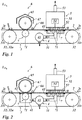
- Fig. 1 shows a device 1 for the surface coating of a substrate 2, comprising a transport device 3, a vacuum suction device 4, a corona device 5 and a coating device 6.
- the transport device 3 is designed as a revolving conveyor belt 31 which is mounted on two deflecting rollers 32 spaced apart from one another, one of the deflecting rollers 32 being designed as a drive roller 32a.
- the conveyor belt 31 is in the in Fig. 1
- the embodiment shown is designed as a seamless band made of stainless steel.
- the conveyor belt 31 revolves in a transport direction 31t.
- the substrate 2 is arranged in a transport section of the transport belt 31 on the transport belt 31 and is fixed on the transport belt 31 by negative pressure.
- the substrate 2 is moved in a transport direction 2t corresponding to the transport direction 31t of the transport belt 31, which corresponds to the transport direction 31 in the transport section.
- the support device 7 arranged below the corona device 5 is in the in Fig. 1
- the illustrated embodiment is formed from four support rollers 71 which are arranged next to one another in the longitudinal extension of the conveyor belt 31.
- the support rollers 71 can in particular rotate at the same speed as the overlying conveyor belt 31 moves, so that the lowest possible friction arises between the support rollers 71 and the conveyor belt 31. That is to say, the support rollers 71 have the same speed on their circumference as the conveyor belt 31 on top.
- the four support rollers 71 are mounted in a rigid or adjustable manner so that they can rotate.
- the support device 7 arranged below the coating device 6 has a support roller 71, the axis of rotation of which is likewise oriented transversely to the transport direction 31t of the transport belt 31.
- the maximum deflection of the conveyor belt 31 under operational load is in the range from 1 ⁇ m to 10 ⁇ m. With such a slight deflection, the conveyor belt can serve particularly advantageously as a mechanical counter-bearing for the substrate.
- the conveyor belt 31 has a thickness in the range from 0.2 mm to 1 mm, preferably in the range from 0.3 mm to 0.5 mm.
- the conveyor belt 31 is made of a material which has a degree of hardness in the range from 450 HV10 to 520 HV10, preferably in the range from 465 HV10 to 500 HV10.
- the conveyor belt 31 can be formed from a steel alloy, preferably from stainless steel. It can also be provided that the conveyor belt is made of copper, aluminum or titanium.
- the surface of the conveyor belt facing the substrate 2 is polished, i.e. it has a roughness depth of less than 0.3 ⁇ m.
- the conveyor belt 31 is designed as a vacuum suction belt 31v with through holes 31d (see Figures 4 to 8 ), by means of which a negative pressure can be formed on the upper side of the conveyor belt 31 which fixes the substrate 2 on the conveyor belt 31.
- the negative pressure is in the range from 10,000 Pascal to 100,000 Pascal (0.1 bar to 1 bar).
- the through holes 31 can be designed as in particular circular bores and / or in particular elliptical elongated holes and / or slots and / or rhombuses.
- a section of the conveyor belt 31 arranged above the sealing element 42 is connected to a suction head 41 of the vacuum suction device 4 in a gas-tight or approximately gas-tight manner.
- the sealing element 42 is designed as a circumferential sealing lip.
- a suction head 41 is provided according to the invention, wherein the
- Suction head 41 is arranged under the corona device 5.
- the vacuum suction device 4 is designed with a vacuum pump 43, the inlet of which is connected to the suction head 41.
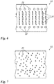
- Fig. 4 and 8th show a first embodiment of the vacuum suction belt 31v.
- Through holes 31 d designed as bores with a circular cross section are arranged in a grid.
- the through holes 31d can have a diameter in the range from 0.2 mm to 5 mm, preferably in have a range of 0.3 mm to 2 mm or have a surface area corresponding to a circular hole of the aforementioned diameter.
- the through holes 31 d have a diameter of 1 mm.
- Fig. 5 shows a second embodiment in which the through holes 31d are designed as diamond-shaped elongated holes which are arranged in a grid.
- Fig. 6 shows a third embodiment, in which the through holes 31 are formed in areas with a different contour. In a central area, the through holes 31d are formed in a diamond shape. In the two edge regions, the through holes 31 are formed with a circular cross section. The grid is also designed differently in areas.
- Fig. 6 Fig. 13 shows a fourth embodiment in which the through holes 31d are randomly arranged.
- the grid can be formed regularly or irregularly or randomly.
- the corona device 5 has a housing 51 which is open on the underside and in which an electrode 52 is arranged.
- the electrode 52 is designed as an air-cooled ceramic electrode and is arranged above the substrate 2.
- the conveyor belt 31 forms a counter electrode 31e, which is in particular grounded.
- the illustrated embodiment has the electrode 52 a cross section of 16 mm x 16 mm and a length that corresponds to the width of the conveyor belt 31 (here: 350 mm).
- the corona device 5 can be arranged with its longitudinal extension transverse to the transport direction 31t of the transport belt 31.
- the electrode 52 is connected as a cathode.
- the counter electrode 31e is connected as an anode.
- the corona gap 5l is adjustable, in particular adjustable in height, and in FIG Fig. 1 illustrated embodiment 1 mm to 2 mm.
- the smallest possible corona gap 51 can be set, for example depending on the thickness and / or the material of the substrate 2, in order to be able to adapt the electric field surrounding and / or penetrating the substrate 2.
- a high electrical voltage is applied to the electrode 52 and the counter-electrode 31e, which is generated by a high-frequency generator 54 with a frequency range of 10 kHz to 60 kHz and forms a field strength of 20 kV / cm to 30 kV / cm in the air gap 5l. Ions are formed by field ionization, which are accelerated in the electric field and adhere to the surface of the substrate 2.
- the corona device 5 has a suction device 53 connected to the housing 51 in a gas-tight manner for suctioning off ozone.
- the ionization of the air in the air gap 5l creates ozone, which has to be sucked off or destroyed.
- the ozone-containing exhaust air is led through an exhaust hose and discharged outside of the production room.
- the ozone-containing exhaust air can be passed through an ozone destroyer, for example an activated carbon filter, before being discharged into the environment. In this way 99.5% of the ozone can be destroyed.
- the exhaust air hose can, for example, have a length of 12 to 15 m. A delivery rate of 4.9 m 3 / min has proven itself.
- the suction device 53 simultaneously forms a cooling device for the electrode 52.
- An embossing roller 67 of the embossing device 65 has on its outer circumference a coating made of an elastomer with a thickness in the range from 3 mm to 10 mm, preferably in the range from 5 mm to 10 mm.
- the elastomer is preferably silicone rubber. In the in Fig. 1 shown In the exemplary embodiment, the silicone rubber has a hardness of 80 ° Shore A.
- the support roller 71 arranged in the area of the embossing device 65 forms a counter-pressure roller for the embossing roller 67.
- the device 1 shown is like that in Fig. 2
- the device shown is designed, with the difference that the coating device 6 is designed as a printing device 61, comprising a printing roller 62 and an ink application device 63.
- Other printing devices can also be provided, for example a printing device based on the screen printing principle and / or based on the inkjet principle.
Landscapes
- Engineering & Computer Science (AREA)
- Mechanical Engineering (AREA)
- Physics & Mathematics (AREA)
- Plasma & Fusion (AREA)
- Fluid Mechanics (AREA)
- Coating Apparatus (AREA)
- Delivering By Means Of Belts And Rollers (AREA)
- Mechanical Treatment Of Semiconductor (AREA)
Description
- Die Erfindung betrifft eine Vorrichtung zur Oberflächenbehandlung eines Substrats nach dem Oberbegriff des Gegenstands des Anspruchs 1.
- Vorrichtungen zur Oberflächenbehandlung eines Substrats werden beispielsweise eingesetzt, um die Oberflächen bogen- oder bahnförmiger Substrate zu bedrucken oder mit einer Übertragungsschicht einer Prägefolie zu beschichten.
- Aus der
DE 10159661 C1 ist eine Heißprägevorrichtung der beschriebenen Art bekannt. - Aus
EP 1 757 450 A2 ist eine Bogendruckmaschine bekannt, welche mehrere Koronaeinrichtungen aufweist, welche dazu dienen, die Haftung einer auf ein Substrat aufgebrachten Beschichtung zu verbessern. -
DE 102 32 255 A1 offenbart eine Rotationsdruckmaschine, welche eine Koronaeinrichtung zur Verbesserung der Haftung einer Bedruckung aufweist. - Aus
DE 10 2012 110 149 A1 ist eine Heißprägevorrichtung bekannt, welche eine Transporteinrichtung für ein Substrat aufweist, die ein umlaufendes dünnes Band enthält. -
EP 2 918 529 A2 offenbart eine Transportvorrichtung mit einem Vakuumsaugband, welches ein Substrat durch die Vorrichtung transportiert. - Aus
WO 2014/146669 A1 ist eine Einheit und ein Verfahren zur Koronabehandlung eines Substrates bekannt. - Aufgabe der vorliegenden Erfindung ist es, eine verbesserte Vorrichtung zur Oberflächenbehandlung eines Substrats anzugeben.
- Erfindungsgemäß wird diese Aufgabe mit dem Gegenstand des Anspruchs 1 gelöst. Es wird eine Vorrichtung zur Oberflächenbehandlung eines Substrats, aufweisend eine Transporteinrichtung, eine Vakuumansaugeinrichtung, eine Koronaeinrichtung und eine Beschichtungseinrichtung, vorgeschlagen, wobei vorgesehen ist, dass die Transporteinrichtung ein Transportband aufweist, dass das Transportband als ein Vakuumsaugband der Vakuumansaugeinrichtung ausgebildet ist, und dass das Transportband als eine Gegenelektrode der Koronaeinrichtung ausgebildet ist. Dabei ist zwischen der dem Substrat abgewandten Seite des Transportbandes und einem Ansaugkopf der Vakuumansaugeinrichtung ein Dichtelement mit einer umlaufenden Dichtlippe angeordnet, wobei der Ansaugkopf unter der Koronaeinrichtung angeordnet ist.
- Die erfindungsgemäße Vorrichtung weist den Vorteil auf, dass die Transporteinrichtung ein Transportband aufweist, das drei Funktionen erfüllt, nämlich den Transport des Substrats, die Lagefixierung des Substrats durch Vakuumansaugung auf dem Transportband und die Bereitstellung einer Elektrode für die Koronaeinrichtung. Diese drei Funktionen kann das Transportband insbesondere gleichzeitig erfüllen, sodass eine sehr vorteilhafte Synergie zwischen diesen Funktionen entsteht.
- Es kann vorgesehen sein, dass das Transportband auf zwei voneinander beabstandeten Umlenkwalzen gelagert ist, wobei eine der Umlenkwalzen als eine Antriebswalze ausgebildet ist.
- Das Transportband kann als ein umlaufendes Band ausgebildet sein, welches insbesondere um die beiden Umlenkwalzen umläuft.
- Weiter kann vorgesehen sein, dass das Transportband im Bereich der Beschichtungseinrichtung und/oder der Koronaeinrichtung auf einer Auflageeinrichtung gelagert ist. Es können mehrere Auflageeinrichtungen vorgesehen sein, die beispielsweise im Bereich der Beschichtungseinrichtung und der Koronaeinrichtung angeordnet sind.
- Die Auflageeinrichtung kann eine Auflagewalze oder mehrere Auflagewalzen, die in Längserstreckung des Transportbandes nebeneinander angeordnet sind, aufweisen. Die Auflagewalzen können dabei insbesondere mit derselben Geschwindigkeit rotieren, wie sich das aufliegende Transportband bewegt, sodass eine möglichst geringe Reibung zwischen den Auflagewalzen und dem Transportband entsteht. D.h. die Auflagewalzen haben an ihrem Umfang dieselbe Geschwindigkeit wie das aufliegende Transportband.
- Die Auflageeinrichtung kann alternativ oder zusätzlich einen insbesondere feststehenden Stützkörper, bevorzugt in Form einer Platte aufweisen.
- Das Transportband kann eine Dicke im Bereich von 0,2 mm bis 1 mm aufweisen, bevorzugt im Bereich von 0,3 mm bis 0,5 mm aufweisen.
- Es kann vorgesehen sein, dass das Transportband aus einem Material ausgebildet ist, das einen Härtegrad im Bereich von 450 HV10 bis 520 HV10, vorzugsweise im Bereich von 465 HV10 bis 500 HV10 aufweist.
- In einer vorteilhaften Ausbildung kann vorgesehen sein, dass das Transportband so ausgebildet und/oder gelagert ist, dass seine maximale Durchbiegung bei betriebsmäßiger Belastung im Bereich von 1 µm bis 10 µm liegt.
- Weiter kann vorgesehen sein, dass die dem Substrat zugewandte Oberfläche des Transportbandes poliert ist, d.h. eine Rautiefe kleiner als 0,3 µm aufweist.
- Das Transportband kann aus einer Stahllegierung ausgebildet sein.
- In einer vorteilhaften Ausbildung kann vorgesehen sein, dass das Transportband aus Edelstahl ausgebildet ist.
- Alternativ kann vorgesehen sein, dass das Transportband aus Kupfer oder Aluminium oder Titan oder aus einer Legierung, die Kupfer und/oder Aluminium und/oder Titan, insbesondere aus einer Legierung, die Aluminium und/oder Titan enthält, ausgebildet ist.
- Das Transportband kann als ein nahtloses Band ausgebildet sein. Ein nahtloses Transportband ohne Stoßstellen bietet über seine gesamte Oberfläche die gleichen Bedingungen hinsichtlich der Eigenschaft als mechanisches Gegenlager für das Substrat.
- Das Transportband kann mehrere Teiltransportbänder aufweisen, die in Transportrichtung aneinander anschließend angeordnet sind, bevorzugt mit möglichst geringem Abstand zwischen den Teiltransportbändern. Diese Teiltransportbänder können gleiche oder auch unterschiedliche Eigenschaften aufweisen, insbesondere bzgl. Material und/oder Härte und/oder Dicke und/oder Biegesteifigkeit. Die für das Transportband oben beschriebenen Eigenschaften gelten auch für die Teiltransportbänder.
- Beispielsweise kann ein erstes Teiltransportband im Bereich der Beschichtungseinrichtung und ein zweites Teiltransportband im Bereich der Koronaeinrichtung angeordnet sein.
- In einer vorteilhaften Ausbildung kann vorgesehen sein, dass zwischen benachbarten Teiltransportbändern ein Auflageelement angeordnet ist, das den Abstandsraum zwischen den benachbarten Teiltransportbändern spaltfrei überbrückt.
- Alternativ kann vorgesehen sein, dass das Transportband als ein Gliederband aus plattenförmigen Gliedern ausgebildet ist, wobei benachbarte Glieder durch ein Drehgelenk so miteinander verbunden sind, dass sie im gestreckten Zustand eine spaltfreie Auflagefläche bilden.
- Es kann vorgesehen sein, dass das Transportband randseitige Transportausnehmungen aufweist, und dass die Umlenkwalzen korrespondierende Zahnkränze aufweisen, die in die Transportausnehmungen eingreifen.
- Weiter kann vorgesehen sein, dass das Transportband Durchgangslöcher, insbesondere eine Vielzahl an Durchgangslöchern aufweist.
- Die Durchgangslöcher können als insbesondere kreisförmige Bohrungen und/oder insbesondere ellipsenförmige Langlöcher und/oder Schlitze und/oder Rauten ausgebildet sein.
- Weiter kann vorgesehen sein, dass die Durchgangslöcher in einem Raster angeordnet sind.
- Das Raster kann regelmäßig oder unregelmäßig oder zufällig ausgebildet sein.
- Es kann auch vorgesehen sein, dass das Raster bereichsweise unterschiedlich ausgebildet ist.
- Die Durchgangslöcher können einen Durchmesser im Bereich von 0,2 mm bis 5 mm, bevorzugt in einem Bereich von 0,3 mm bis 2 mm aufweisen oder einen einem kreisförmigen Loch vorgenannten Durchmessers entsprechenden Flächeninhalt aufweisen, insbesondere wenn das Durchgangsloch nicht kreisförmig ausgebildet ist.
- Erfindungsgemäß ist vorgesehen, dass zwischen der dem Substrat abgewandten Seite des Transportbandes und einem Ansaugkopf der Vakuumansaugeinrichtung ein Dichtelement mit einer umlaufenden Dichtlippe angeordnet ist.
- In einer vorteilhaften Ausbildung kann vorgesehen sein, dass der Unterdruck der Vakuumansaugvorrichtung im Bereich 10000 Pascal bis 100000 Pascal (0,1 bar bis 1 bar) insbesondere im Bereich von 10000 Pascal bis 75000 Pascal (0,1 bar bis 0,75 bar) liegt.
- Es kann vorgesehen sein, dass die Koronaeinrichtung ein an seiner Unterseite offenes Gehäuse aufweist, in dessen unteren Endabschnitt eine Elektrode angeordnet ist. Die Elektrode kann beispielsweise als eine luftgekühlte Keramik-Elektrode ausgebildet sein, einen Querschnitt von 16 mm x 16 mm und eine Länge, die der Breite des Transportbandes entspricht, aufweisen. Dabei kann die Koronaeinrichtung mit ihrer Längserstreckung quer zur Transportrichtung des Transportbandes und über dem Substrat angeordnet sein.
- Es kann vorgesehen sein, dass die Elektrode der Koronaeinrichtung die Kathode und das Transportband als Gegenelektrode die Anode der Koronaeinrichtung bilden, wobei zwischen der Kathode und der Anode ein Koronaspalt ausgebildet ist. Der Koronaspalt kann beispielsweise im Bereich von 1 mm bis 2 mm liegen.
- An die Elektrode und die Gegenelektrode ist eine hohe elektrische Spannung angelegt, die durch einen Hochfrequenzgenerator mit einem Frequenzbereich von 10 kHz bis 60 kHz erzeugt wird und in dem Luftspalt eine Feldstärke von 20 kV/cm bis 30 kV/cm ausbildet. Durch Feldionisation werden Ionen gebildet, die im elektrischen Feld beschleunigt werden und sich an die Oberfläche des Substrats anheften.
- Durch die Bildung polarer, funktionieller Gruppen kann der polare Anteil der Oberflächenspannung des Substrats angehoben werden. Die Oberfläche des Substrats wird elektrisch aufgeladen, die Oberflächenenergie des Substrats wird erhöht. Für eine gute Benetzung des Substrats mit einer Flüssigkeit, also z.B. eines UV-Klebers oder einer Drucktinte, sollte die Oberflächenspannung des Substrats ca.10 mN/m bis 15 mN/m höher liegen, als die Oberflächenspannung der Flüssigkeit. Beispielsweise kann die Oberflächenspannung einer Tinte zwischen 20 mN/m bis 25 mN/m und die Oberflächenspannung eines zu bedruckenden folienförmigen Substrats zwischen 30 mN/m bis 35 mN/m liegen. Mittels der Koronaeinrichtung kann die Oberflächenspannung des Substrats auf ca. 40 mN/m bis 45 mN/m angehoben werden, wodurch sich dieses Substrat bedrucken lässt.
- Der Koronaspalt kann einstellbar ausgebildet sein. Beispielsweise kann die Elektrode der Koronaeinrichtung höheneinstellbar ausgebildet sein. Dadurch kann ein möglichst kleiner Koronaspalt einstellbar sein, beispielsweise abhängig von der Dicke und/oder vom Material des Substrats, um das das Substrat umschließende und/oder durchdringende elektrische Feld anpassen zu können.
- Die Koronaeinrichtung kann eine gasdicht mit dem Gehäuse verbundene Absaugvorrichtung zur Ozonabsaugung aufweisen. Durch die Ionisation der Luft in dem Koronaspalt entsteht Ozon, welches abgesaugt oder vernichtet werden muss. Die ozonhaltige Abluft wird über einen Abluftschlauch geführt und außerhalb des Fertigungsraumes abgeführt. Optional kann die ozonhaltige Abluft vor der Ableitung in die Umwelt durch einen Ozonvernichter geleitet werden, beispielsweise ein Aktivkohlefilter. Auf diese Weise können 99,5 % des Ozons vernichtet werden. Der Abbluftschlauch kann beispielsweise eine Länge von 12 m bis 15 m aufweisen. Eine Förderleistung von 4,9 m3/min hat sich bewährt. Die Absaugvorrichtung kann gleichzeitig eine Kühlvorrichtung für die Elektrode bilden.
- Es kann vorgesehen sein, dass die Beschichtungseinrichtung als eine Druckeinrichtung ausgebildet ist. Die Druckeinrichtung kann beispielsweise eine Druckwalze und eine Farbauftragsvorrichtung aufweisen und/oder nach dem Siebdruckprinzip und/oder nach dem Tintenstrahlprinzip arbeiten.
- Es kann auch vorgesehen sein, dass die Beschichtungseinrichtung eine Prägevorrichtung zur Übertragung einer auf einer Trägerschicht einer Transferfolie, insbesondere einer Heißprägefolie oder Kaltprägefolie angeordneten Übertragungsschicht auf das Substrat aufweist.
- Eine Prägewalze der Prägevorrichtung kann an ihrem Außenumfang eine Beschichtung aus einem Elastomer mit einer Dicke im Bereich von 3 mm bis 10 mm aufweisen, bevorzugt im Bereich von 5 mm bis 10 mm. Bei dem Elastomer handelt es sich vorzugsweise um Silikonkautschuk. Der Silikonkautschuk weist bevorzugt eine Härte im Bereich von 60° Shore A bis 95° Shore A, bevorzugt im Bereich von 70° Shore A bis 90° Shore A auf. Eine im Bereich der Prägevorrichtung angeordnete Auflagewalze bildet eine Gegendruckwalze für die Prägewalze.
- Die Beschichtungseinrichtung kann bevorzugt stromabwärts hinter der Koronaeinrichtung angeordnet sein. Dadurch kann die Beschichtung des Substrats nach der Behandlung der Oberfläche des Substrats mittels der Koronaeinrichtung erfolgen.
- Stromabwärts nach der Koronaeinrichtung können auch mehrere Beschichtungsstationen stromabwärts hintereinander angeordnet sein, beispielsweise mehrere Druckeinrichtungen und/oder mehrere Prägevorrichtung und/oder eine Druckeinrichtung und eine Prägevorrichtung oder andere Kombinationen davon. Die Druckeinrichtungen können dabei jeweils nach dem gleichen Druckverfahren und/oder nach unterschiedlichen Druckverfahren arbeiten. Die Prägevorrichtungen können dabei jeweils nach dem gleichen Verfahren und/oder nach unterschiedlichen Verfahren arbeiten.
- Ebenso ist es möglich, stromabwärts nach der Koronaeinrichtung und bevorzugt nach der mindestens einen Beschichtungseinrichtung weitere Bearbeitungsstationen wie Sortierstationen, Stanzstationen, Blindprägestationen, Faltstationen oder andere Bearbeitungsstationen zur Bearbeitung des Substrats anzuordnen.
- Die Transferfolie weist eine auf einer Trägerschicht angeordnete Übertragungsschicht auf. Die Trägerschicht kann z.B. aus PET oder aus Polypropylen, Polystyrol, PVC, PMMA, ABS, Polyamid sein. Die Heißprägefolie ist so angeordnet, dass die Übertragungsschicht der Oberseite des zu beprägenden Substrats zugewandt ist. Die Übertragungsschicht kann mit einer hitzeaktivierbaren Kleberschicht beschichtet sein oder selbstklebend (Kaltkleber) ausgebildet sein. Zwischen der Übertragungsschicht und der Trägerschicht kann eine Trennschicht angeordnet sein, die das Ablösen der Übertragungsschicht von der Trägerschicht erleichtert.
- Die Übertragungsschicht der Transferfolie weist im Allgemeinen mehrere Schichten auf, insbesondere eine Ablöseschicht (beispielsweise aus Wachs oder wachshaltigen Verbindungen), eine Schutzlackschicht, eine hitzeaktivierbare Kleberschicht. Zusätzlich können eine oder mehrere, flächig partiell oder vollflächig aufgebrachte, Dekorationsschichten und/oder Funktionsschichten enthalten sein. Dekorationsschichten sind zum Beispiel farbige (opak oder transparent oder transluzent) Lackschichten, Metallschichten oder Reliefstrukturen (haptisch oder optisch refraktiv oder optisch diffraktiv wirkend). Funktionsschichten sind beispielsweise elektrisch leitende Schichten (Metall, ITO (ITO = Indium Tin Oxide)), elektrisch halbleitende Schichten (z.B. Halbleiterpolymere) oder elektrisch nichtleitende Schichten (elektrisch isolierende Lackschichten) oder optisch mattierende oder anti-reflektierend wirkende Schichten (z.B. mit mikroskopischen Mattstrukturen) oder die Haftwirkung und/oder die Oberflächenspannung modifizierende Strukturen (Lotus-Effekt-Strukturen oder ähnliche). Zwischen den einzelnen Schichten können zusätzliche Hilfsschichten, insbesondere Haftvermittlerschichten vorhanden sein. Die einzelnen Schichten der Übertragungslage sind etwa zwischen 1 nm und 50 µm dick.
- Das Substrat ist bevorzugt ein flexibles Substrat, beispielsweise Papier mit einem Flächengewicht von 30 g/m2 bis 350 g/m2, bevorzugt 80 g/m2 bis 350 g/m2 oder Karton oder Kunststoff oder ein Hybridmaterial aus mehreren Papier- und Kunststoffschichten oder ein Laminat aus mehreren Papier- und/oder Kunststoffschichten.
- Die Erfindung wird nun anhand von Ausführungsbeispielen näher erläutert. Es zeigen
- Fig. 1
- ein erstes Ausführungsbeispiel der erfindungsgemäßen Vorrichtung in schematischer Darstellung;
- Fig. 2
- ein zweites Ausführungsbeispiel der erfindungsgemäßen Vorrichtung in schematischer Darstellung;
- Fig. 3
- ein drittes Ausführungsbeispiel der erfindungsgemäßen Vorrichtung in schematischer Darstellung;
- Fig. 4
- ein erstes Ausführungsbeispiel eines Transportbandes in
Fig. 1 in schematischer Draufsicht; - Fig. 5
- ein zweites Ausführungsbeispiel des Transportbandes in
Fig. 1 in schematischer Draufsicht; - Fig. 6
- ein drittes Ausführungsbeispiel des Transportbandes in
Fig. 1 in schematischer Draufsicht; - Fig. 7
- ein viertes Ausführungsbeispiel des Transportbandes in
Fig. 1 in schematischer Draufsicht; - Fig. 8
- ein viertes Ausführungsbeispiel des Transportbandes in
Fig. 1 in der Draufsicht. -
Fig. 1 zeigt eine Vorrichtung 1 zur Oberflächenbeschichtung eines Substrats 2, umfassend eine Transporteinrichtung 3, eine Vakuumansaugeinrichtung 4, eine Koronaeinrichtung 5 und eine Beschichtungseinrichtung 6. - Die Transporteinrichtung 3 ist als ein umlaufendes Transportband 31 ausgebildet, das auf zwei voneinander beabstandeten Umlenkwalzen 32 gelagert ist, wobei eine der Umlenkwalzen 32 als eine Antriebswalze 32a ausgebildet ist. Das Transportband 31 ist in der in
Fig. 1 gezeigten Ausführung als ein nahtloses Band aus Edelstahl ausgebildet. - Es kann auch vorgesehen sein, dass das Transportband 31 als ein Gliederband aus plattenförmigen Gliedern ausgebildet ist, wobei benachbarte Glieder durch ein Drehgelenk so miteinander verbunden sind, dass sie im gestreckten Zustand eine spaltfreie Auflagefläche bilden. Vorteilhafterweise kann das Transportband 31 bei dieser in den Figuren nicht dargestellten Ausbildung randseitige Transportausnehmungen aufweisen, die mit korrespondierenden Zahnkränzen zusammenwirken, die mit den Umlenkwalzen 32 drehstarr verbunden sind.
- Das Transportband 31 läuft in einer Transportrichtung 31t um. Das Substrat 2 ist in einem Transportabschnitt des Transportbandes 31 auf dem Transportband 31 angeordnet und ist durch Unterdruck auf dem Transportband 31 fixiert. Das Substrat 2 wird entsprechend der Transportrichtung 31t des Transportbandes 31 in einer Transportrichtung 2t bewegt, die der Transportrichtung 31 in dem Transportabschnitt entspricht.
- Das Transportband 31 ist im Bereich der Koronaeinrichtung 5 und im Bereich der Beschichtungseinrichtung 6 auf einer Auflageeinrichtung 7 gelagert. Die Beschichtungseinrichtung 6 ist stromabwärts hinter der Koronaeinrichtung 5 angeordnet.
- Die unter der Koronaeinrichtung 5 angeordnete Auflageeinrichtung 7 ist in dem in
Fig. 1 dargestellten Ausführungsbeispiel aus vier Auflagewalzen 71 ausgebildet, die in Längserstreckung des Transportbandes 31 nebeneinander angeordnet sind. Die Auflagewalzen 71 können dabei insbesondere mit derselben Geschwindigkeit rotieren, wie sich das aufliegende Transportband 31 bewegt, sodass eine möglichst geringe Reibung zwischen den Auflagewalzen 71 und dem Transportband 31 entsteht. D.h. die Auflagewalzen 71 haben an ihrem Umfang dieselbe Geschwindigkeit wie das aufliegende Transportband 31. Die vier Auflagewalzen 71 sind starr oder einstellbar drehbar gelagert. Die Drehachsen der Auflagewalzen 71 können an ihrer außenseitigen Lagerstelle so einstellbar befestigt sein, dass beispielsweise eine Einstellung mit einer exzentrischen Lagerung und entsprechender Fixierung der Lagerung eine Einstellung der Drehachsen relativ zum Transportband 31 möglich ist. Die Drehachsen der Auflagewalzen 71 sind quer zu der Transportrichtung 31t des Transportbandes 31 ausgerichtet. Alternativ oder zusätzlich zu den Auflagewalzen 71 kann auch eine plattenförmige Auflage insbesondere als fest stehender Stützkörper vorgesehen sein. - Die unter der Beschichtungseinrichtung 6 angeordnete Auflageeinrichtung 7 weist eine Auflagewalze 71 auf, deren Drehachse ebenfalls quer zu der Transportrichtung 31t des Transportbandes 31 ausgerichtet ist.
- In dem in
Fig. 1 dargestellten Ausführungsbeispiel liegt die maximale Durchbiegung des Transportbandes 31 bei betriebsmäßiger Belastung im Bereich von 1 µm bis 10 µm. Durch eine derartig geringe Durchbiegung kann das Transportband besonders vorteilhaft als mechanisches Gegenlager für das Substrat dienen. - Das Transportband 31 weist eine Dicke im Bereich von 0,2 mm bis 1 mm auf, bevorzugt im Bereich von 0,3 mm bis 0,5 mm.
- Das Transportband 31 ist aus einem Material ausgebildet, das einen Härtegrad im Bereich von 450 HV10 bis 520 HV10, vorzugsweise im Bereich von 465 HV10 bis 500 HV10 aufweist.
- Das Transportband 31 kann aus einer Stahllegierung ausgebildet sein, bevorzugt aus Edelstahl. Es kann auch vorgesehen sein, das Transportband aus Kupfer, Aluminium oder Titan ausgebildet ist.
- Die dem Substrat 2 zugewandte Oberfläche des Transportbandes ist poliert, d.h. sie weist eine Rautiefe kleiner als 0,3 µm auf.
- Das Transportband 31 ist als ein Vakuumsaugband 31v mit Durchgangslöchern 31 d (siehe
Fig. 4 bis 8 ) ausgebildet, über die ein Unterdruck auf der Oberseite des Transportbandes 31 ausbildbar ist, welcher das Substrat 2 auf dem Transportband 31 fixiert. In dem inFig. 1 dargestellten Ausführungsbeispiel liegt der Unterdruck im Bereich von 10000 Pascal bis 100000 Pascal (0,1 bar bis 1 bar). - Die Durchgangslöcher 31 können als insbesondere kreisförmige Bohrungen und/oder insbesondere ellipsenförmige Langlöcher und/oder Schlitze und/oder Rauten ausgebildet sein.
- Über ein an der dem Substrat 2 abgewandten Seite des Transportbandes 31 angeordnetes Dichtelement 42 ist ein über dem Dichtelement 42 angeordneter Abschnitt des Transportbandes 31 mit einem Ansaugkopf 41 der Vakuumansaugeinrichtung 4 gasdicht oder annähernd gasdicht verbunden. Das Dichtelement 42 ist als eine umlaufende Dichtlippe ausgebildet. In dem in
Fig. 1 dargestellten Ausführungsbeispiel ist erfindungsgemäß ein Ansaugkopf 41 vorgesehen, wobei der - Ansaugkopf 41 unter der Koronaeinrichtung 5 angeordnet ist. Die Vakuumansaugeinrichtung 4 ist mit einer Vakuumpumpe 43 ausgebildet, deren Eingang mit dem Ansaugkopf 41 verbunden ist.
-
Fig. 4 und8 zeigen ein erstes Ausführungsbeispiel des Vakuumsaugbandes 31v. Als Bohrungen mit kreisförmigem Querschnitt ausgebildete Durchgangslöcher 31 d sind in einem Raster angeordnet. Die Durchgangslöcher 31d können einen Durchmesser im Bereich von 0,2 mm bis 5 mm, bevorzugt in einem Bereich von 0,3 mm bis 2 mm aufweisen oder einen einem kreisförmigen Loch vorgenannten Durchmessers entsprechenden Flächeninhalt aufweisen. In dem inFig. 7 dargestellten Ausführungsbeispiel weisen die Durchgangslöcher 31 d einen Durchmesser von 1 mm auf. -
Fig. 5 zeigt ein zweites Ausführungsbeispiel, bei dem die Durchgangslöcher 31d als rautenförmige Langlöcher ausgebildet sind, die in einem Raster angeordnet sind. -
Fig. 6 zeigt ein drittes Ausführungsbeispiel, bei dem die Durchgangslöcher 31 bereichsweise mit einer unterschiedlichen Kontur ausgebildet sind. In einem mittleren Bereich sind die Durchgangslöcher 31d rautenförmig ausgebildet. In den beiden Randbereichen sind die Durchgangslöcher 31 mit kreisförmigem Querschnitt ausgebildet. Auch das Raster ist bereichsweise unterschiedlich ausgebildet. -
Fig. 6 zeigt ein viertes Ausführungsbeispiel, bei dem die Durchgangslöcher 31d zufällig verteilt angeordnet sind. - Wie die vorbeschriebenen Ausführungsbeispiele zeigen, kann das Raster regelmäßig oder unregelmäßig oder zufällig ausgebildet sein.
- Die Koronaeinrichtung 5 weist ein an der Unterseite offenes Gehäuse 51 auf, in dem eine Elektrode 52 angeordnet ist. Die Elektrode 52 ist als eine luftgekühlte Keramik-Elektrode ausgebildet und über dem Substrat 2 angeordnet. Das Transportband 31 bildet eine Gegenelektrode 31e, die insbesondere geerdet ist. In dem in
Fig. 1 dargestellten Ausführungsbeispiel weist die Elektrode 52 einen Querschnitt von 16 mm x 16 mm auf und eine Länge, die der Breite des Transportbandes 31 entspricht (hier: 350 mm). Dabei kann die Koronaeinrichtung 5 mit ihrer Längserstreckung quer zur Transportrichtung 31t des Transportbandes 31 angeordnet sein. Die Elektrode 52 ist als Kathode geschaltet. Die Gegenelektrode 31e ist als Anode geschaltet. Zwischen der Elektrode 52 und der Gegenelektrode 31e ist ein Koronaspalt 5l ausgebildet, zwischen dem die Koronaentladung erzeugt wird. Der Koronaspalt 5l ist einstellbar, insbesondere höheneinstellbar und beträgt in dem inFig. 1 dargestellten Ausführungsbeispiel 1 mm bis 2 mm. Dadurch kann ein möglichst kleiner Koronaspalt 5l einstellbar sein, beispielsweise abhängig von der Dicke und/oder vom Material des Substrats 2, um das das Substrat 2 umschließende und/oder durchdringende elektrische Feld anpassen zu können. - An die Elektrode 52 und die Gegenelektrode 31e ist eine hohe elektrische Spannung angelegt, die durch einen Hochfrequenzgenerator 54 mit einem Frequenzbereich von 10 kHz bis 60 kHz erzeugt wird und in dem Luftspalt 5l eine Feldstärke von 20 kV/cm bis 30 kV/cm ausbildet. Durch Feldionisation werden Ionen gebildet, die im elektrischen Feld beschleunigt werden und sich an die Oberfläche des Substrats 2 anheften.
- Durch die Bildung polarer, funktionieller Gruppen kann der polare Anteil der Oberflächenspannung des Substrats 2 angehoben werden. Die Oberfläche des Substrats 2 wird elektrisch aufgeladen, die Oberflächenenergie des Substrats 2 wird erhöht. Für eine gute Benetzung des Substrats 2 mit einer Flüssigkeit, also z.B. eines UV-Klebers oder einer Drucktinte, sollte die Oberflächenspannung des Substrats 2 ca. 10 mN/m bis 15 mN/m höher liegen, als die Oberflächenspannung der Flüssigkeit. Beispielsweise kann die Oberflächenspannung einer Tinte zwischen 20 mN/m bis 25 mN/m und die Oberflächenspannung eines zu bedruckenden folienförmigen Substrats 2 zwischen 30 mN/m bis 35 mN/m liegen. Mittels der Koronaeinrichtung 5 kann die Oberflächenspannung des Substrats 2 auf ca. 40 mN/m bis 45 mN/m angehoben werden, wodurch sich dieses Substrat 2 bedrucken lässt.
- Die Koronaeinrichtung 5 weist eine gasdicht mit dem Gehäuse 51 verbundene Absaugvorrichtung 53 zur Ozonabsaugung auf. Durch die Ionisation der Luft in dem Luftspalt 5l entsteht Ozon, welches abgesaugt oder vernichtet werden muss. Die ozonhaltige Abluft wird über einen Abluftschlauch geführt und außerhalb des Fertigungsraumes abgeführt. Optional kann die ozonhaltige Abluft vor der Ableitung in die Umwelt durch einen Ozonvernichter geleitet werden, beispielsweise ein Aktivkohlefilter. Auf diese Weise können 99,5 % des Ozons vernichtet werden. Der Abbluftschlauch kann beispielsweise eine Länge von 12 bis 15 m aufweisen. Eine Förderleistung von 4,9 m3/min hat sich bewährt. Die Absaugvorrichtung 53 bildet gleichzeitig eine Kühlvorrichtung für die Elektrode 52.
- Die Beschichtungseinrichtung 6 ist als eine Prägevorrichtung 65 zur Übertragung einer auf einer Trägerschicht einer Transferfolie 66, insbesondere einer Heißprägefolie oder Kaltprägefolie angeordneten Übertragungsschicht auf das Substrat 2 ausgebildet.
- Eine Prägewalze 67 der Prägevorrichtung 65 weist an ihrem Außenumfang eine Beschichtung aus einem Elastomer mit einer Dicke im Bereich von 3 mm bis 10 mm auf, bevorzugt im Bereich von 5 mm bis 10 mm. Bei dem Elastomer handelt es sich vorzugsweise um Silikonkautschuk. In dem in
Fig. 1 dargestellten Ausführungsbeispiel weist der Silikonkautschuk eine Härte von 80° Shore A auf. Die im Bereich der Prägevorrichtung 65 angeordnete Auflagewalze 71 bildet eine Gegendruckwalze für die Prägewalze 67. - In dem in
Fig. 2 dargestellten Ausführungsbeispiel sind im Unterschied zuFig. 1 zwei Ansaugköpfe 41 vorgesehen, wobei der eine Ansaugkopf 41 unter der Koronaeinrichtung 5 und der andere Ansaugkopf 41 unter der Beschichtungseinrichtung 6 angeordnet ist. Die Vakuumansaugeinrichtung 4 ist mit einer Vakuumpumpe 43 ausgebildet, deren Eingänge mit den beiden Ansaugköpfen 41 verbunden sind. - Die in
Fig. 3 dargestellte Vorrichtung 1 ist wie die inFig. 2 dargestellte Vorrichtung ausgebildet, mit dem Unterschied, dass die Beschichtungseinrichtung 6 als eine Druckeinrichtung 61 ausgebildet ist, umfassend eine Druckwalze 62 und eine Farbauftragsvorrichtung 63. Es können auch andere Druckeinrichtungen vorgesehen sein, beispielsweise eine Druckeinrichtung nach dem Siebdruckprinzip und/oder nach dem Tintenstrahlprinzip. -
- 1
- Vorrichtung
- 2
- Substrat
- 2t
- Transportrichtung
- 3
- Transporteinrichtung
- 3t
- Transportrichtung
- 4
- Vakuumansaugeinrichtung
- 5
- Koronaeinrichtung
- 5l
- Luftspalt
- 6
- Beschichtungseinrichtung
- 7
- Auflageeinrichtung
- 31
- Transportband
- 31 d
- Durchgangsloch
- 31 e
- Gegenelektrode
- 31t
- Transportrichtung
- 31 v
- Vakuumsaugband
- 32
- Umlenkwalzen
- 32a
- Antriebswalze
- 41
- Ansaugkopf
- 42
- Dichtelement
- 43
- Vakuumpumpe
- 51
- Gehäuse
- 52
- Elektrode
- 53
- Absaugvorrichtung
- 54
- Hochfrequenzgenerator
- 61
- Druckeinrichtung
- 62
- Druckwalze
- 63
- Farbauftragseinrichtung
- 65
- Prägevorrichtung
- 66
- Transferfolie
- 67
- Prägewalze
- 71
- Auflagewalze
Claims (14)
- Vorrichtung (1) zur Oberflächenbehandlung eines Substrats (2), aufweisend eine Transporteinrichtung (3), eine Vakuumansaugeinrichtung (4), eine Koronaeinrichtung (5) und eine Beschichtungseinrichtung (6),
wobei die Transporteinrichtung (3) ein Transportband (31) aufweist und
das Transportband (31) als ein Vakuumsaugband (31v) der Vakuumansaugeinrichtung (4) ausgebildet ist, dadurch gekennzeichnet,
dass das Transportband (31) als eine Gegenelektrode (31 e) der Koronaeinrichtung (5) ausgebildet ist, wobei zwischen der dem Substrat (2) abgewandten Seite des Transportbandes (31) und einem Ansaugkopf (41) der Vakuumansaugeinrichtung (4) ein Dichtelement (42) mit einer umlaufenden Dichtlippe angeordnet ist und der Ansaugkopf (41) unter der Koronaeinrichtung (5) angeordnet ist. - Vorrichtung nach Anspruch 1,
dadurch gekennzeichnet,
dass das Transportband (31) auf zwei voneinander beabstandeten Umlenkwalzen (32) gelagert ist, wobei eine der Umlenkwalzen (32) als eine Antriebswalze (32a) ausgebildet ist. - Vorrichtung nach Anspruch 1 oder 2,
dadurch gekennzeichnet,
dass das Transportband (31) als ein umlaufendes Band ausgebildet ist. - Vorrichtung nach einem der vorangehenden Ansprüche,
dadurch gekennzeichnet,
dass das Transportband (31) im Bereich der Koronaeinrichtung (5) und/oder der Beschichtungseinrichtung (6) auf einer Auflageeinrichtung (7) gelagert ist, insbesondere wobei die Auflageeinrichtung (7) eine Auflagewalze (71) oder mehrere Auflagewalzen (71), die in Längserstreckung des Transportbandes (31) nebeneinander angeordnet sind, aufweist. - Vorrichtung nach einem der vorangehenden Ansprüche,
dadurch gekennzeichnet,
dass das Transportband (31) eine Dicke im Bereich von 0,2 mm bis 1 mm aufweist, bevorzugt im Bereich von 0,3 mm bis 0,5 mm aufweist, und/oder aus einem Material ausgebildet ist, das einen Härtegrad im Bereich von 450 HV10 bis 520 HV10, vorzugsweise im Bereich von 465 HV10 bis 500 HV10 aufweist, und/oder so ausgebildet und/oder gelagert ist, dass seine maximale Durchbiegung bei betriebsmäßiger Belastung im Bereich von 1 µm bis 10 µm liegt. - Vorrichtung nach einem der vorangehenden Ansprüche,
dadurch gekennzeichnet,
dass das Transportband (31) aus einer Stahllegierung ausgebildet ist, insbesondere wobei das Transportband (31) aus Edelstahl ausgebildet ist. - Vorrichtung nach einem der vorangehenden Ansprüche,
dadurch gekennzeichnet,
dass das Transportband (31) als ein nahtloses Band ausgebildet ist. - Vorrichtung nach einem der Ansprüche 1 bis 7,
dadurch gekennzeichnet,
dass das Transportband (31) mehrere Teiltransportbänder aufweist, die in Transportrichtung (31t) aneinander anschließend angeordnet sind, insbesondere wobei zwischen benachbarten Teiltransportbändern ein Auflageelement angeordnet ist, das den Abstandsraum zwischen den benachbarten Teiltransportbändern spaltfrei überbrückt, und/oder dass das Transportband (31) als ein Gliederband aus plattenförmigen Gliedern ausgebildet ist, wobei benachbarte Glieder durch ein Drehgelenk so miteinander verbunden sind, dass sie im gestreckten Zustand eine spaltfreie Auflagefläche bilden, insbesondere wobei das Transportband (31) randseitige Transportausnehmungen aufweist, und
dass die Umlenkwalzen korrespondierende Zahnkränze aufweisen, die in die Transportausnehmungen eingreifen. - Vorrichtung nach einem der vorangehenden Ansprüche,
dadurch gekennzeichnet,
dass das Transportband (31) Durchgangslöcher (31 d) aufweist, insbesondere wobei die Durchgangslöcher (31 d) als Bohrungen und/oder Langlöcher und/oder Schlitze und/oder Rauten ausgebildet sind, insbesondere bevorzugt wobei die Durchgangslöcher (31d) in einem Raster angeordnet sind, besonders bevorzugt wobei das Raster regelmäßig oder unregelmäßig oder zufällig ausgebildet ist und/oder bereichsweise unterschiedlich ausgebildet ist. - Vorrichtung nach Anspruch 9,
dadurch gekennzeichnet,
dass die Durchgangslöcher (31 d) einen Durchmesser im Bereich von 0,2 mm bis 5 mm, bevorzugt in einem Bereich von 0,3 mm bis 2 mm aufweisen oder einen einem kreisförmigen Loch vorgenannten Durchmessers entsprechenden Flächeninhalt aufweisen. - Vorrichtung nach einem der vorangehenden Ansprüche,
dadurch gekennzeichnet,
dass der Unterdruck der Vakuumansaugeinrichtung (4) im Bereich von 10000 Pascal bis 100000 Pascal (0,1 bar bis 1 bar) liegt, bevorzugt im Bereich von 10000 Pascal bis 75000 Pascal (0,1 bar bis 0,75 bar) liegt. - Vorrichtung nach einem der vorangehenden Ansprüche,
dadurch gekennzeichnet,
dass die Koronaeinrichtung (5) ein an seiner Unterseite offenes Gehäuse (51) aufweist, in dessen unteren Endabschnitt eine Elektrode (52) angeordnet ist, insbesondere wobei die Elektrode (52) der Koronaeinrichtung (5) die Kathode und das Transportband (31) als Gegenelektrode die Anode der Koronaeinrichtung (5) bilden, wobei zwischen der Kathode und der Anode ein Koronaspalt (5l) ausgebildet ist, insbesondere bevorzugt wobei der Koronaspalt (5l) einstellbar ausgebildet ist. - Vorrichtung nach einem der vorangehenden Ansprüche,
dadurch gekennzeichnet,
dass die Beschichtungseinrichtung (6) als eine Druckeinrichtung (61) ausgebildet ist. - Vorrichtung nach einem der Ansprüche 1 bis 13,
dadurch gekennzeichnet,
dass die Beschichtungseinrichtung (6) als eine Prägevorrichtung (65) zur Übertragung einer auf einer Trägerschicht einer Transferfolie (66) angeordneten Übertragungsschicht auf das Substrat (2) ausgebildet ist.
Priority Applications (1)
| Application Number | Priority Date | Filing Date | Title |
|---|---|---|---|
| PL17716837T PL3458265T3 (pl) | 2016-05-17 | 2017-04-06 | Urządzenie do obróbki powierzchni podłoża z metaliczną taśmą transportową |
Applications Claiming Priority (2)
| Application Number | Priority Date | Filing Date | Title |
|---|---|---|---|
| DE102016109044.1A DE102016109044B3 (de) | 2016-05-17 | 2016-05-17 | Vorrichtung zur Oberflächenbehandlung eines Substrats |
| PCT/EP2017/058291 WO2017198390A1 (de) | 2016-05-17 | 2017-04-06 | Vorrichtung zur oberflächenbehandlung eines substrats mit einem metallischen transportband |
Publications (2)
| Publication Number | Publication Date |
|---|---|
| EP3458265A1 EP3458265A1 (de) | 2019-03-27 |
| EP3458265B1 true EP3458265B1 (de) | 2021-08-11 |
Family
ID=58536961
Family Applications (1)
| Application Number | Title | Priority Date | Filing Date |
|---|---|---|---|
| EP17716837.4A Active EP3458265B1 (de) | 2016-05-17 | 2017-04-06 | Vorrichtung zur oberflächenbehandlung eines substrats mit einem metallischen transportband |
Country Status (11)
| Country | Link |
|---|---|
| US (1) | US11155427B2 (de) |
| EP (1) | EP3458265B1 (de) |
| JP (1) | JP6946347B2 (de) |
| KR (1) | KR102304657B1 (de) |
| CN (1) | CN109311310B (de) |
| DE (1) | DE102016109044B3 (de) |
| ES (1) | ES2886963T3 (de) |
| HU (1) | HUE056316T2 (de) |
| IL (1) | IL262861B (de) |
| PL (1) | PL3458265T3 (de) |
| WO (1) | WO2017198390A1 (de) |
Families Citing this family (11)
| Publication number | Priority date | Publication date | Assignee | Title |
|---|---|---|---|---|
| CN108057567B (zh) * | 2017-12-19 | 2019-07-19 | 浙江奔富新能源股份有限公司 | 一种涂布机 |
| CN108639731B (zh) * | 2018-05-04 | 2019-11-22 | 利辛县宝隆橡塑密封件有限责任公司 | 一种橡胶垫圈生产用的出料机构 |
| EP3851210B1 (de) * | 2020-01-14 | 2025-12-24 | Jesús Francisco Barberan Latorre | Beschichtungsrolle |
| CN111942015B (zh) * | 2020-08-05 | 2022-04-01 | 上海弗列加滤清器有限公司 | 一种用于增加产品表面张力的装置 |
| CN112659652B (zh) * | 2020-12-24 | 2022-09-09 | 武汉龙发包装有限公司 | 一种瓦楞纸板及其生产线 |
| CN112938559A (zh) * | 2021-03-24 | 2021-06-11 | 深圳市全印数码科技有限公司 | 一种印花机输送系统及印花机 |
| DE102021001582A1 (de) | 2021-03-25 | 2022-09-29 | Giesecke+Devrient Currency Technology Gmbh | Optisch variables Sicherheitselement, Herstellungsverfahren und Prägeanordnung |
| CN113511008A (zh) * | 2021-03-31 | 2021-10-19 | 合阳县虹媒文化有限公司 | 一种仿石浮雕模板制作装置 |
| CN117283857B (zh) * | 2023-09-28 | 2025-04-15 | 蠡县华都橡胶机带有限公司 | 一种橡胶输送带生产制作用的脱模装置 |
| EP4696518A1 (de) | 2024-08-14 | 2026-02-18 | Canon Production Printing Holding B.V. | Vorrichtung zur koronabehandlung |
| CN119795747A (zh) * | 2025-03-11 | 2025-04-11 | 陕西彩航包装装潢有限公司 | 一种ps版逆象uv标签的印刷生产设备 |
Family Cites Families (30)
| Publication number | Priority date | Publication date | Assignee | Title |
|---|---|---|---|---|
| CH621421A5 (en) | 1976-03-31 | 1981-01-30 | Du Pont | Magnetographic dry copying process and device for carrying it out |
| DE3134615A1 (de) * | 1981-09-01 | 1983-03-10 | Agfa-Gevaert Ag, 5090 Leverkusen | Verfahren und vorrichtung zur vorbehandlung von fotografischen traegermaterialien |
| JP2505273Y2 (ja) * | 1990-01-26 | 1996-07-24 | 池上通信機株式会社 | 被検体搬送装置 |
| US5397413A (en) * | 1992-04-10 | 1995-03-14 | Fiberweb North America, Inc. | Apparatus and method for producing a web of thermoplastic filaments |
| US5651313A (en) * | 1994-09-23 | 1997-07-29 | Ward Holding Company, Inc. | Paperboard processing machine with vacuum transfer system |
| US5634185A (en) | 1996-06-27 | 1997-05-27 | Xerox Corporation | Removing toner additive films, spots, comets and residual toner on a flexible planar member using ultrasonic vibrational energy |
| US5895738A (en) | 1997-08-22 | 1999-04-20 | Xerox Corporation | Extension of xerocolorgraphy to full color printing employing additive RGB+ K colors |
| US20030038420A1 (en) * | 2000-10-30 | 2003-02-27 | Vutek, Inc. | Printing system with vacuum table |
| JP2003168593A (ja) * | 2001-11-29 | 2003-06-13 | Sekisui Chem Co Ltd | 放電プラズマ処理装置 |
| DE10159661C1 (de) * | 2001-12-05 | 2003-02-20 | Kurz Leonhard Fa | Heißprägemaschine mit einer Prägestation |
| DE10232255A1 (de) * | 2002-07-17 | 2004-02-05 | Koenig & Bauer Ag | Rotationsdruckmaschine |
| DE10232225A1 (de) * | 2002-07-17 | 2004-01-29 | Kuhn Maschinentechnik Gmbh & Co. Kg | Segmentlade-Einrichtung für Stangenmaterial |
| DE10312153A1 (de) * | 2003-03-17 | 2004-10-07 | Ebe Hesterman | Maschine für den Bogenrotationsdruck oder Bogenbeschichtung |
| AU2004320020B2 (en) * | 2004-05-20 | 2011-06-09 | Softal Electronic Gmbh | Continuous and semi-continuous treatment of textile materials integrating CORONA discharge |
| JP2006076202A (ja) | 2004-09-10 | 2006-03-23 | Fuji Photo Film Co Ltd | 液体吐出装置及び電界付与方法 |
| JP2006290624A (ja) * | 2005-04-01 | 2006-10-26 | Heidelberger Druckmas Ag | ベルトコンベヤによって被印刷体枚葉紙を搬送する方法、およびその方法に適したベルトコンベヤ |
| DE102006019792A1 (de) * | 2005-05-04 | 2006-11-09 | Ist Metz Gmbh | Vorrichtung und Verfahren zur Koronabehandlung von Flachmaterial |
| US20090277590A1 (en) | 2005-05-04 | 2009-11-12 | Ist Metz Gmbh | Device and method for corona treatment of flat material |
| DE102005029360B4 (de) * | 2005-06-24 | 2011-11-10 | Softal Corona & Plasma Gmbh | Zwei Verfahren zur kontinuierlichen Atmosphärendruck Plasmabehandlung von Werkstücken, insbesondere Materialplatten oder -bahnen |
| DE102005038834A1 (de) * | 2005-08-17 | 2007-02-22 | Man Roland Druckmaschinen Ag | Bogendruckmaschine |
| CN100455717C (zh) * | 2006-03-02 | 2009-01-28 | 大连理工大学 | 一种电晕放电低温等离子体织物表面改性处理装置 |
| JP2009073589A (ja) * | 2007-09-19 | 2009-04-09 | Seiko Epson Corp | ライン記録方式の画像形成装置及び画像形成方法 |
| DK2251453T3 (da) * | 2009-05-13 | 2014-07-07 | Sio2 Medical Products Inc | Beholderholder |
| JP5842546B2 (ja) * | 2011-11-04 | 2016-01-13 | 株式会社リコー | インクジェット記録装置 |
| EP2802455B1 (de) * | 2012-01-13 | 2016-04-27 | OCE-Technologies B.V. | Vorrichtung zur behandlung der korona |
| DE102012110149B4 (de) * | 2012-10-24 | 2019-02-07 | Leonhard Kurz Stiftung & Co. Kg | Heißprägevorrichtung |
| DK177766B3 (da) * | 2013-03-19 | 2018-04-30 | Tresu As | Enhed og fremgangsmåde til koronabehandling |
| CN203390404U (zh) * | 2013-07-22 | 2014-01-15 | 广东大族粤铭激光科技股份有限公司 | 激光切割装置防磨损送料机构 |
| US9493307B2 (en) * | 2014-03-11 | 2016-11-15 | Sun Automation, Inc. | Conveyors for box making machines |
| JP6252326B2 (ja) * | 2014-04-10 | 2017-12-27 | 京セラドキュメントソリューションズ株式会社 | 搬送装置、及びインクジェット記録装置 |
-
2016
- 2016-05-17 DE DE102016109044.1A patent/DE102016109044B3/de active Active
-
2017
- 2017-04-06 CN CN201780038153.7A patent/CN109311310B/zh active Active
- 2017-04-06 IL IL262861A patent/IL262861B/en unknown
- 2017-04-06 KR KR1020187036278A patent/KR102304657B1/ko active Active
- 2017-04-06 HU HUE17716837A patent/HUE056316T2/hu unknown
- 2017-04-06 PL PL17716837T patent/PL3458265T3/pl unknown
- 2017-04-06 EP EP17716837.4A patent/EP3458265B1/de active Active
- 2017-04-06 JP JP2018560600A patent/JP6946347B2/ja active Active
- 2017-04-06 US US16/301,265 patent/US11155427B2/en active Active
- 2017-04-06 ES ES17716837T patent/ES2886963T3/es active Active
- 2017-04-06 WO PCT/EP2017/058291 patent/WO2017198390A1/de not_active Ceased
Non-Patent Citations (1)
| Title |
|---|
| None * |
Also Published As
| Publication number | Publication date |
|---|---|
| US20190210823A1 (en) | 2019-07-11 |
| DE102016109044B3 (de) | 2017-07-06 |
| CN109311310A (zh) | 2019-02-05 |
| IL262861B (en) | 2022-07-01 |
| WO2017198390A1 (de) | 2017-11-23 |
| IL262861A (en) | 2018-12-31 |
| JP2019517968A (ja) | 2019-06-27 |
| ES2886963T3 (es) | 2021-12-21 |
| HUE056316T2 (hu) | 2022-02-28 |
| CN109311310B (zh) | 2021-09-21 |
| KR102304657B1 (ko) | 2021-09-27 |
| EP3458265A1 (de) | 2019-03-27 |
| JP6946347B2 (ja) | 2021-10-06 |
| PL3458265T3 (pl) | 2021-11-08 |
| US11155427B2 (en) | 2021-10-26 |
| KR20190008332A (ko) | 2019-01-23 |
Similar Documents
| Publication | Publication Date | Title |
|---|---|---|
| EP3458265B1 (de) | Vorrichtung zur oberflächenbehandlung eines substrats mit einem metallischen transportband | |
| EP2856848B1 (de) | Verfahren und anlage zum herstellen eines mehrschichtelements sowie mehrschichtelement | |
| WO2005076206A1 (de) | Verfahren und vorrichtung zum kontinuierlichen herstellen elektronischer folienbauteile sowie elektronisches folienbauteil | |
| EP3113947A1 (de) | Rollenmaterial für eine oder mit einer submikrometerschicht auf einem flexiblen träger und verwendung davon | |
| DE602006000397T2 (de) | Mantel für einen Prägungszylinder oder einen Transportzylinder einer Druckerpresse | |
| WO2023247491A1 (de) | Umlenkeinrichtung zum trennen und abziehen einer materialbahn | |
| DE102012207148A1 (de) | Vorrichtung und Verfahren zum Beeinflussen von Flüssigkeitströpfchen oder Partikeln am Walzenauslauf eines Walzenpaares | |
| DE102014005851B4 (de) | Verfahren und Vorrichtung zur Herstellung von Elastomer-Aktuatoren | |
| EP1029388B1 (de) | Corona-station zur vorbehandlung von einer materialbahn | |
| DE102008009156B4 (de) | Anordnung zum Ableiten elektrostatischer Ladungen von einem Bedruckstoff | |
| DE102012016375A1 (de) | Verfahren zur Herstellung dielektrischer Elastomeraktoren | |
| DE2754425A1 (de) | Verfahren und vorrichtung zum kontinuierlichen herstellen von zwei- oder mehrlagigen bahnfoermigen verbundwerkstoffen | |
| EP2572887B1 (de) | Behälterbedruckungsanlage | |
| EP0258353A1 (de) | Haftklebendbeschichteter gegenstand und verfahren zu seiner herstellung | |
| DE102017212828A1 (de) | Vorrichtung zum Beschichten von Nutzen, eine Druckmaschine und Verfahren zum Beschichten von Nutzen | |
| EP0761458A1 (de) | Verfahren und Vorrichtung zur elektrostatischen Substratübertragung | |
| EP4423825B1 (de) | Verfahren und vorrichtung zur herstellung von membran-baugruppen | |
| EP1757450B1 (de) | Bogendruckmaschine | |
| DE102016203413A1 (de) | Erhöhung der Abzugskraft durch selektive Plasmavorbehandlung | |
| DE102017101284A1 (de) | Zweischichtwalzen | |
| EP0598313A1 (de) | Verfahren und Vorrichtung zum Verbinden textiler Flächengebilde | |
| EP2692528A1 (de) | Ablage von Folien | |
| DE102009009460A1 (de) | Bogenführungszylinder mit Aufzug in einer Verarbeitungsmaschine | |
| EP2735437A1 (de) | Laminierplatte und Verfahren zu deren Herstellung sowie Anordnung zum Laminieren | |
| DE20203719U1 (de) | Schichtkörper zum Verhüten des Verschmierens von Maschinenteilen oder Bedruckstoffen in einer Verarbeitungsmaschine |
Legal Events
| Date | Code | Title | Description |
|---|---|---|---|
| STAA | Information on the status of an ep patent application or granted ep patent |
Free format text: STATUS: UNKNOWN |
|
| STAA | Information on the status of an ep patent application or granted ep patent |
Free format text: STATUS: THE INTERNATIONAL PUBLICATION HAS BEEN MADE |
|
| PUAI | Public reference made under article 153(3) epc to a published international application that has entered the european phase |
Free format text: ORIGINAL CODE: 0009012 |
|
| STAA | Information on the status of an ep patent application or granted ep patent |
Free format text: STATUS: REQUEST FOR EXAMINATION WAS MADE |
|
| 17P | Request for examination filed |
Effective date: 20181206 |
|
| AK | Designated contracting states |
Kind code of ref document: A1 Designated state(s): AL AT BE BG CH CY CZ DE DK EE ES FI FR GB GR HR HU IE IS IT LI LT LU LV MC MK MT NL NO PL PT RO RS SE SI SK SM TR |
|
| AX | Request for extension of the european patent |
Extension state: BA ME |
|
| DAV | Request for validation of the european patent (deleted) | ||
| DAX | Request for extension of the european patent (deleted) | ||
| STAA | Information on the status of an ep patent application or granted ep patent |
Free format text: STATUS: EXAMINATION IS IN PROGRESS |
|
| 17Q | First examination report despatched |
Effective date: 20200827 |
|
| GRAP | Despatch of communication of intention to grant a patent |
Free format text: ORIGINAL CODE: EPIDOSNIGR1 |
|
| STAA | Information on the status of an ep patent application or granted ep patent |
Free format text: STATUS: GRANT OF PATENT IS INTENDED |
|
| INTG | Intention to grant announced |
Effective date: 20210316 |
|
| RIN1 | Information on inventor provided before grant (corrected) |
Inventor name: KOSALLA, KONSTANTIN Inventor name: TRIEPEL, MICHAEL |
|
| GRAS | Grant fee paid |
Free format text: ORIGINAL CODE: EPIDOSNIGR3 |
|
| GRAA | (expected) grant |
Free format text: ORIGINAL CODE: 0009210 |
|
| STAA | Information on the status of an ep patent application or granted ep patent |
Free format text: STATUS: THE PATENT HAS BEEN GRANTED |
|
| AK | Designated contracting states |
Kind code of ref document: B1 Designated state(s): AL AT BE BG CH CY CZ DE DK EE ES FI FR GB GR HR HU IE IS IT LI LT LU LV MC MK MT NL NO PL PT RO RS SE SI SK SM TR |
|
| REG | Reference to a national code |
Ref country code: CH Ref legal event code: EP |
|
| REG | Reference to a national code |
Ref country code: DE Ref legal event code: R096 Ref document number: 502017011166 Country of ref document: DE |
|
| REG | Reference to a national code |
Ref country code: NL Ref legal event code: FP |
|
| REG | Reference to a national code |
Ref country code: IE Ref legal event code: FG4D Free format text: LANGUAGE OF EP DOCUMENT: GERMAN Ref country code: AT Ref legal event code: REF Ref document number: 1418985 Country of ref document: AT Kind code of ref document: T Effective date: 20210915 |
|
| REG | Reference to a national code |
Ref country code: LT Ref legal event code: MG9D |
|
| REG | Reference to a national code |
Ref country code: ES Ref legal event code: FG2A Ref document number: 2886963 Country of ref document: ES Kind code of ref document: T3 Effective date: 20211221 |
|
| PG25 | Lapsed in a contracting state [announced via postgrant information from national office to epo] |
Ref country code: SE Free format text: LAPSE BECAUSE OF FAILURE TO SUBMIT A TRANSLATION OF THE DESCRIPTION OR TO PAY THE FEE WITHIN THE PRESCRIBED TIME-LIMIT Effective date: 20210811 Ref country code: RS Free format text: LAPSE BECAUSE OF FAILURE TO SUBMIT A TRANSLATION OF THE DESCRIPTION OR TO PAY THE FEE WITHIN THE PRESCRIBED TIME-LIMIT Effective date: 20210811 Ref country code: HR Free format text: LAPSE BECAUSE OF FAILURE TO SUBMIT A TRANSLATION OF THE DESCRIPTION OR TO PAY THE FEE WITHIN THE PRESCRIBED TIME-LIMIT Effective date: 20210811 Ref country code: NO Free format text: LAPSE BECAUSE OF FAILURE TO SUBMIT A TRANSLATION OF THE DESCRIPTION OR TO PAY THE FEE WITHIN THE PRESCRIBED TIME-LIMIT Effective date: 20211111 Ref country code: PT Free format text: LAPSE BECAUSE OF FAILURE TO SUBMIT A TRANSLATION OF THE DESCRIPTION OR TO PAY THE FEE WITHIN THE PRESCRIBED TIME-LIMIT Effective date: 20211213 Ref country code: FI Free format text: LAPSE BECAUSE OF FAILURE TO SUBMIT A TRANSLATION OF THE DESCRIPTION OR TO PAY THE FEE WITHIN THE PRESCRIBED TIME-LIMIT Effective date: 20210811 Ref country code: LT Free format text: LAPSE BECAUSE OF FAILURE TO SUBMIT A TRANSLATION OF THE DESCRIPTION OR TO PAY THE FEE WITHIN THE PRESCRIBED TIME-LIMIT Effective date: 20210811 Ref country code: BG Free format text: LAPSE BECAUSE OF FAILURE TO SUBMIT A TRANSLATION OF THE DESCRIPTION OR TO PAY THE FEE WITHIN THE PRESCRIBED TIME-LIMIT Effective date: 20211111 |
|
| PG25 | Lapsed in a contracting state [announced via postgrant information from national office to epo] |
Ref country code: LV Free format text: LAPSE BECAUSE OF FAILURE TO SUBMIT A TRANSLATION OF THE DESCRIPTION OR TO PAY THE FEE WITHIN THE PRESCRIBED TIME-LIMIT Effective date: 20210811 Ref country code: GR Free format text: LAPSE BECAUSE OF FAILURE TO SUBMIT A TRANSLATION OF THE DESCRIPTION OR TO PAY THE FEE WITHIN THE PRESCRIBED TIME-LIMIT Effective date: 20211112 |
|
| REG | Reference to a national code |
Ref country code: HU Ref legal event code: AG4A Ref document number: E056316 Country of ref document: HU |
|
| PG25 | Lapsed in a contracting state [announced via postgrant information from national office to epo] |
Ref country code: DK Free format text: LAPSE BECAUSE OF FAILURE TO SUBMIT A TRANSLATION OF THE DESCRIPTION OR TO PAY THE FEE WITHIN THE PRESCRIBED TIME-LIMIT Effective date: 20210811 |
|
| REG | Reference to a national code |
Ref country code: DE Ref legal event code: R097 Ref document number: 502017011166 Country of ref document: DE |
|
| PG25 | Lapsed in a contracting state [announced via postgrant information from national office to epo] |
Ref country code: SM Free format text: LAPSE BECAUSE OF FAILURE TO SUBMIT A TRANSLATION OF THE DESCRIPTION OR TO PAY THE FEE WITHIN THE PRESCRIBED TIME-LIMIT Effective date: 20210811 Ref country code: SK Free format text: LAPSE BECAUSE OF FAILURE TO SUBMIT A TRANSLATION OF THE DESCRIPTION OR TO PAY THE FEE WITHIN THE PRESCRIBED TIME-LIMIT Effective date: 20210811 Ref country code: RO Free format text: LAPSE BECAUSE OF FAILURE TO SUBMIT A TRANSLATION OF THE DESCRIPTION OR TO PAY THE FEE WITHIN THE PRESCRIBED TIME-LIMIT Effective date: 20210811 Ref country code: EE Free format text: LAPSE BECAUSE OF FAILURE TO SUBMIT A TRANSLATION OF THE DESCRIPTION OR TO PAY THE FEE WITHIN THE PRESCRIBED TIME-LIMIT Effective date: 20210811 Ref country code: CZ Free format text: LAPSE BECAUSE OF FAILURE TO SUBMIT A TRANSLATION OF THE DESCRIPTION OR TO PAY THE FEE WITHIN THE PRESCRIBED TIME-LIMIT Effective date: 20210811 Ref country code: AL Free format text: LAPSE BECAUSE OF FAILURE TO SUBMIT A TRANSLATION OF THE DESCRIPTION OR TO PAY THE FEE WITHIN THE PRESCRIBED TIME-LIMIT Effective date: 20210811 |
|
| PLBE | No opposition filed within time limit |
Free format text: ORIGINAL CODE: 0009261 |
|
| STAA | Information on the status of an ep patent application or granted ep patent |
Free format text: STATUS: NO OPPOSITION FILED WITHIN TIME LIMIT |
|
| 26N | No opposition filed |
Effective date: 20220512 |
|
| PG25 | Lapsed in a contracting state [announced via postgrant information from national office to epo] |
Ref country code: SI Free format text: LAPSE BECAUSE OF FAILURE TO SUBMIT A TRANSLATION OF THE DESCRIPTION OR TO PAY THE FEE WITHIN THE PRESCRIBED TIME-LIMIT Effective date: 20210811 |
|
| REG | Reference to a national code |
Ref country code: DE Ref legal event code: R119 Ref document number: 502017011166 Country of ref document: DE |
|
| REG | Reference to a national code |
Ref country code: BE Ref legal event code: MM Effective date: 20220430 |
|
| PG25 | Lapsed in a contracting state [announced via postgrant information from national office to epo] |
Ref country code: MC Free format text: LAPSE BECAUSE OF FAILURE TO SUBMIT A TRANSLATION OF THE DESCRIPTION OR TO PAY THE FEE WITHIN THE PRESCRIBED TIME-LIMIT Effective date: 20210811 Ref country code: LU Free format text: LAPSE BECAUSE OF NON-PAYMENT OF DUE FEES Effective date: 20220406 Ref country code: DE Free format text: LAPSE BECAUSE OF NON-PAYMENT OF DUE FEES Effective date: 20221103 |
|
| PG25 | Lapsed in a contracting state [announced via postgrant information from national office to epo] |
Ref country code: BE Free format text: LAPSE BECAUSE OF NON-PAYMENT OF DUE FEES Effective date: 20220430 |
|
| PG25 | Lapsed in a contracting state [announced via postgrant information from national office to epo] |
Ref country code: IE Free format text: LAPSE BECAUSE OF NON-PAYMENT OF DUE FEES Effective date: 20220406 |
|
| REG | Reference to a national code |
Ref country code: AT Ref legal event code: MM01 Ref document number: 1418985 Country of ref document: AT Kind code of ref document: T Effective date: 20220406 |
|
| PG25 | Lapsed in a contracting state [announced via postgrant information from national office to epo] |
Ref country code: AT Free format text: LAPSE BECAUSE OF NON-PAYMENT OF DUE FEES Effective date: 20220406 |
|
| PG25 | Lapsed in a contracting state [announced via postgrant information from national office to epo] |
Ref country code: MK Free format text: LAPSE BECAUSE OF FAILURE TO SUBMIT A TRANSLATION OF THE DESCRIPTION OR TO PAY THE FEE WITHIN THE PRESCRIBED TIME-LIMIT Effective date: 20210811 Ref country code: CY Free format text: LAPSE BECAUSE OF FAILURE TO SUBMIT A TRANSLATION OF THE DESCRIPTION OR TO PAY THE FEE WITHIN THE PRESCRIBED TIME-LIMIT Effective date: 20210811 |
|
| PG25 | Lapsed in a contracting state [announced via postgrant information from national office to epo] |
Ref country code: MT Free format text: LAPSE BECAUSE OF FAILURE TO SUBMIT A TRANSLATION OF THE DESCRIPTION OR TO PAY THE FEE WITHIN THE PRESCRIBED TIME-LIMIT Effective date: 20210811 |
|
| PGFP | Annual fee paid to national office [announced via postgrant information from national office to epo] |
Ref country code: PL Payment date: 20250214 Year of fee payment: 9 |
|
| PGFP | Annual fee paid to national office [announced via postgrant information from national office to epo] |
Ref country code: TR Payment date: 20250326 Year of fee payment: 9 |
|
| PGFP | Annual fee paid to national office [announced via postgrant information from national office to epo] |
Ref country code: NL Payment date: 20250422 Year of fee payment: 9 |
|
| PGFP | Annual fee paid to national office [announced via postgrant information from national office to epo] |
Ref country code: ES Payment date: 20250519 Year of fee payment: 9 Ref country code: GB Payment date: 20250423 Year of fee payment: 9 |
|
| PGFP | Annual fee paid to national office [announced via postgrant information from national office to epo] |
Ref country code: HU Payment date: 20250331 Year of fee payment: 9 |
|
| PGFP | Annual fee paid to national office [announced via postgrant information from national office to epo] |
Ref country code: IT Payment date: 20250430 Year of fee payment: 9 |
|
| PGFP | Annual fee paid to national office [announced via postgrant information from national office to epo] |
Ref country code: FR Payment date: 20250425 Year of fee payment: 9 |
|
| PGFP | Annual fee paid to national office [announced via postgrant information from national office to epo] |
Ref country code: CH Payment date: 20250501 Year of fee payment: 9 |