EP2802455B1 - Vorrichtung zur behandlung der korona - Google Patents
Vorrichtung zur behandlung der korona Download PDFInfo
- Publication number
- EP2802455B1 EP2802455B1 EP13700552.6A EP13700552A EP2802455B1 EP 2802455 B1 EP2802455 B1 EP 2802455B1 EP 13700552 A EP13700552 A EP 13700552A EP 2802455 B1 EP2802455 B1 EP 2802455B1
- Authority
- EP
- European Patent Office
- Prior art keywords
- sheet
- corona
- treatment device
- electrode
- sheet guide
- Prior art date
- Legal status (The legal status is an assumption and is not a legal conclusion. Google has not performed a legal analysis and makes no representation as to the accuracy of the status listed.)
- Active
Links
- 238000003851 corona treatment Methods 0.000 title claims description 87
- 239000000463 material Substances 0.000 claims description 99
- 238000009832 plasma treatment Methods 0.000 claims description 57
- 238000003825 pressing Methods 0.000 claims description 38
- 229910010293 ceramic material Inorganic materials 0.000 claims description 11
- 238000007639 printing Methods 0.000 claims description 10
- 229920000642 polymer Polymers 0.000 claims description 7
- 239000011248 coating agent Substances 0.000 claims description 4
- 238000000576 coating method Methods 0.000 claims description 4
- 230000032258 transport Effects 0.000 description 171
- 210000002683 foot Anatomy 0.000 description 29
- 239000010410 layer Substances 0.000 description 12
- 238000004381 surface treatment Methods 0.000 description 12
- 238000010276 construction Methods 0.000 description 11
- 229910052581 Si3N4 Inorganic materials 0.000 description 8
- 230000008901 benefit Effects 0.000 description 8
- HQVNEWCFYHHQES-UHFFFAOYSA-N silicon nitride Chemical compound N12[Si]34N5[Si]62N3[Si]51N64 HQVNEWCFYHHQES-UHFFFAOYSA-N 0.000 description 8
- 238000011109 contamination Methods 0.000 description 7
- 238000007599 discharging Methods 0.000 description 5
- 238000000034 method Methods 0.000 description 5
- 230000008569 process Effects 0.000 description 5
- CBENFWSGALASAD-UHFFFAOYSA-N Ozone Chemical compound [O-][O+]=O CBENFWSGALASAD-UHFFFAOYSA-N 0.000 description 4
- 239000004809 Teflon Substances 0.000 description 4
- 229920006362 Teflon® Polymers 0.000 description 4
- 230000001965 increasing effect Effects 0.000 description 4
- TWNQGVIAIRXVLR-UHFFFAOYSA-N oxo(oxoalumanyloxy)alumane Chemical compound O=[Al]O[Al]=O TWNQGVIAIRXVLR-UHFFFAOYSA-N 0.000 description 4
- HBMJWWWQQXIZIP-UHFFFAOYSA-N silicon carbide Chemical compound [Si+]#[C-] HBMJWWWQQXIZIP-UHFFFAOYSA-N 0.000 description 4
- 239000000919 ceramic Substances 0.000 description 3
- 230000007423 decrease Effects 0.000 description 3
- 238000001035 drying Methods 0.000 description 3
- 230000005684 electric field Effects 0.000 description 3
- 238000007641 inkjet printing Methods 0.000 description 3
- 239000007788 liquid Substances 0.000 description 2
- 230000004048 modification Effects 0.000 description 2
- 238000012986 modification Methods 0.000 description 2
- 239000002344 surface layer Substances 0.000 description 2
- 229920000271 Kevlar® Polymers 0.000 description 1
- 229910000831 Steel Inorganic materials 0.000 description 1
- 229910052782 aluminium Inorganic materials 0.000 description 1
- XAGFODPZIPBFFR-UHFFFAOYSA-N aluminium Chemical compound [Al] XAGFODPZIPBFFR-UHFFFAOYSA-N 0.000 description 1
- 239000004760 aramid Substances 0.000 description 1
- 229920003235 aromatic polyamide Polymers 0.000 description 1
- 230000008859 change Effects 0.000 description 1
- 239000003086 colorant Substances 0.000 description 1
- 230000001419 dependent effect Effects 0.000 description 1
- 230000000694 effects Effects 0.000 description 1
- 230000005611 electricity Effects 0.000 description 1
- 230000002708 enhancing effect Effects 0.000 description 1
- 238000001704 evaporation Methods 0.000 description 1
- 239000004744 fabric Substances 0.000 description 1
- 230000006870 function Effects 0.000 description 1
- 239000011521 glass Substances 0.000 description 1
- 238000010438 heat treatment Methods 0.000 description 1
- 229920001903 high density polyethylene Polymers 0.000 description 1
- 229920006158 high molecular weight polymer Polymers 0.000 description 1
- 239000004700 high-density polyethylene Substances 0.000 description 1
- 239000011810 insulating material Substances 0.000 description 1
- 230000003993 interaction Effects 0.000 description 1
- 239000004761 kevlar Substances 0.000 description 1
- 230000003472 neutralizing effect Effects 0.000 description 1
- 239000000123 paper Substances 0.000 description 1
- 239000004033 plastic Substances 0.000 description 1
- 229920003023 plastic Polymers 0.000 description 1
- 239000013047 polymeric layer Substances 0.000 description 1
- 230000007480 spreading Effects 0.000 description 1
- 230000003068 static effect Effects 0.000 description 1
- 239000010959 steel Substances 0.000 description 1
- 230000007723 transport mechanism Effects 0.000 description 1
Images


Classifications
-
- B—PERFORMING OPERATIONS; TRANSPORTING
- B41—PRINTING; LINING MACHINES; TYPEWRITERS; STAMPS
- B41J—TYPEWRITERS; SELECTIVE PRINTING MECHANISMS, i.e. MECHANISMS PRINTING OTHERWISE THAN FROM A FORME; CORRECTION OF TYPOGRAPHICAL ERRORS
- B41J2/00—Typewriters or selective printing mechanisms characterised by the printing or marking process for which they are designed
- B41J2/385—Typewriters or selective printing mechanisms characterised by the printing or marking process for which they are designed characterised by selective supply of electric current or selective application of magnetism to a printing or impression-transfer material
-
- H—ELECTRICITY
- H01—ELECTRIC ELEMENTS
- H01T—SPARK GAPS; OVERVOLTAGE ARRESTERS USING SPARK GAPS; SPARKING PLUGS; CORONA DEVICES; GENERATING IONS TO BE INTRODUCED INTO NON-ENCLOSED GASES
- H01T19/00—Devices providing for corona discharge
-
- B—PERFORMING OPERATIONS; TRANSPORTING
- B29—WORKING OF PLASTICS; WORKING OF SUBSTANCES IN A PLASTIC STATE IN GENERAL
- B29C—SHAPING OR JOINING OF PLASTICS; SHAPING OF MATERIAL IN A PLASTIC STATE, NOT OTHERWISE PROVIDED FOR; AFTER-TREATMENT OF THE SHAPED PRODUCTS, e.g. REPAIRING
- B29C59/00—Surface shaping of articles, e.g. embossing; Apparatus therefor
- B29C59/10—Surface shaping of articles, e.g. embossing; Apparatus therefor by electric discharge treatment
-
- H—ELECTRICITY
- H05—ELECTRIC TECHNIQUES NOT OTHERWISE PROVIDED FOR
- H05H—PLASMA TECHNIQUE; PRODUCTION OF ACCELERATED ELECTRICALLY-CHARGED PARTICLES OR OF NEUTRONS; PRODUCTION OR ACCELERATION OF NEUTRAL MOLECULAR OR ATOMIC BEAMS
- H05H1/00—Generating plasma; Handling plasma
- H05H1/24—Generating plasma
- H05H1/2406—Generating plasma using dielectric barrier discharges, i.e. with a dielectric interposed between the electrodes
-
- H—ELECTRICITY
- H05—ELECTRIC TECHNIQUES NOT OTHERWISE PROVIDED FOR
- H05H—PLASMA TECHNIQUE; PRODUCTION OF ACCELERATED ELECTRICALLY-CHARGED PARTICLES OR OF NEUTRONS; PRODUCTION OR ACCELERATION OF NEUTRAL MOLECULAR OR ATOMIC BEAMS
- H05H1/00—Generating plasma; Handling plasma
- H05H1/24—Generating plasma
- H05H1/47—Generating plasma using corona discharges
-
- B—PERFORMING OPERATIONS; TRANSPORTING
- B41—PRINTING; LINING MACHINES; TYPEWRITERS; STAMPS
- B41J—TYPEWRITERS; SELECTIVE PRINTING MECHANISMS, i.e. MECHANISMS PRINTING OTHERWISE THAN FROM A FORME; CORRECTION OF TYPOGRAPHICAL ERRORS
- B41J11/00—Devices or arrangements of selective printing mechanisms, e.g. ink-jet printers or thermal printers, for supporting or handling copy material in sheet or web form
- B41J11/0015—Devices or arrangements of selective printing mechanisms, e.g. ink-jet printers or thermal printers, for supporting or handling copy material in sheet or web form for treating before, during or after printing or for uniform coating or laminating the copy material before or after printing
Definitions
- the present invention relates to a corona treatment device for treating a cut sheet material.
- the present invention further relates to a printing system comprising the corona treatment device for treating a cut sheet material.
- a disadvantage of the web transport mechanism is that it is not able to controllably transport a cut sheet material along the corona unit.
- the leading edge and trailing edge of the cut sheet material can not be controlled all the time and therefore the distance of the cut sheet material to the corona unit may vary during transport along the corona unit.
- the quality of the corona treatment of the surface of the cut sheet material is not controlled.
- Another disadvantage is that in case the thickness of the cut sheet varies, the transport path of the cut sheet material needs to be adjusted.
- Another disadvantage is that the cut sheet material may get damaged or stuck by hitting the corona unit during transport along the corona unit.
- a sheet and web cleaner having a pressurized air ionizing bar, which discharges ionized air at high velocity onto a moving sheet or web.
- the sheet or web is transported along a path along elongated air discharge openings.
- the treatment by the discharge ionized air provides a charge to the sheet or web for neutralizing the static electricity on both the sheet or web material being processed.
- a corona discharge device including an electrically conductive shield case and a corona wire.
- the wire applies a corona discharge to the back surface of a sheet material.
- a guide member is provided for preventing entry of a sheet material in the shield case.
- the corona discharge device provides a charge to the sheet material for transferring a toner image on a rotating drum to a sheet material or for peeling the sheet material when in intimate contact with the surface of the rotating drum.
- a disadvantage of the known devices is that the treatment is not able to chemically modify the surface of a cut sheet material.
- a rotary printing machine comprising a corona treatment device for treating a sheet, the corona treatment device comprising a cylinder and a corona electrode, wherein the cylinder is arranged as a counter electrode.
- the corona electrode is arranged facing the cylinder for forming a corona gap in between one another.
- the corona treatment device is arranged for treating the sheet to enhance adhesion of print material to the sheet.
- a corona treatment device for treating a cut sheet material
- the corona treatment device comprising a corona means for applying a corona treatment onto a surface of a sheet
- the corona means comprising a corona electrode
- a sheet transporting means for transporting the sheet in the direction of a transport path along the corona means
- a plurality of sheet guide elements for guiding the sheet along the corona means, the plurality of sheet guide elements being positioned between the corona electrode and the transport path thereby providing a predetermined distance between the transport path and the corona electrode
- the plurality of sheet guide elements comprises at least a first sheet guide element extending in a direction at a first angle with respect to the sheet transport direction
- the plurality of sheet guide elements comprises at least a first sheet guide element extending in a direction at a first angle in a plane of the sheet transport direction with respect to the sheet transport direction, and wherein the first angle in said plane of the sheet transport direction of the sheet guide element together with
- the corona treatment device comprises a corona means for applying a corona plasma treatment onto a surface of a sheet, the corona means comprising a corona electrode and a counter electrode in close proximity of each other, a sheet transporting means for transporting the cut sheet material in the direction of a transport path, the transport path of the cut sheet material being positioned through the corona means and in between the corona electrode and the counter electrode, and a plurality of sheet guide elements for guiding the sheet along the corona electrode, the plurality of sheet guide elements being positioned between the corona electrode and the transport path thereby providing a predetermined distance between the transport path and the corona electrode, wherein the plurality of sheet guide elements comprises at least a first sheet guide element extending in a direction at a first angle with respect to the sheet transport direction.
- the corona treatment device comprises a corona means.
- the corona means comprises a corona electrode and a counter electrode.
- the corona means provides a plasma in between the corona electrode and the counter electrode.
- the plasma according to the invention is provided in the direction of the surface of the sheet, which is transported along the transport path in between the corona electrode and the counter electrode.
- the corona electrode and the counter electrode are preferably arranged substantially parallel to each other at both sides of the transport path in order to provide a uniform plasma in a high voltage alternating electrical field.
- the plasma which is formed in between the corona electrode and the counter electrode is provided in order to chemically modify the surface of the cut sheet material. It is known that materials such as plastics, cloth, or paper may be passed through the plasma in order to change the surface energy of the material as is known from, for example, FR2578176 and GB925354 .
- the plasma may chemically modify the surface energy of the cut sheet material when it is controllably passed in between the corona electrode and the counter electrode in order to adapt interaction of the surface of the cut sheet material to ink droplets by providing a plurality of sheet guide elements according to the present invention.
- the plasma may modify the surface energy of the cut sheet material thereby reducing inter color bleed between adjacent ink droplets or increasing ink droplet spreading of each individual ink droplet.
- the plasma is formed and provided directly to the surface of the cut sheet by providing a high voltage alternating electrical field between the corona electrode and the counter electrode during the transport of the cut sheet through the transport path.
- the corona electrode may be a ceramic bar, a discharge electrode, a curved electrode, or any other corona discharge elements.
- the corona means may also comprise a plurality of corona electrodes.
- the counter electrode is preferably electrically grounded.
- the counter electrode is arranged at the other side of the transport path opposite of the corona electrode.
- the corona means may provide a corona plasma treatment to the surface of the cut sheet in the transport path between the corona electrode and the counter electrode.
- the counter electrode may have a flat surface and may also have a curved surface.
- the surface of the counter electrode preferably has a lower curvature than the surface of the corona electrode.
- the counter electrode may have a bare electrical conducting surface and the counter electrode may comprise a dielectric surface layer.
- a dielectric sheet supporting surface may be arranged in between the counter electrode and the transport path for supporting the cut sheet material during transport through the transport path.
- the sheet transporting means is configured for transporting the sheet in the direction of a transport path along the corona electrode.
- the transport path is positioned in between the corona electrode and the counter electrode.
- the sheet transporting means may push the sheet in the direction of a transport path and/or may pull the sheet in the direction of a transport path.
- the sheet transporting means may comprise a sheet input pinch roller for pushing the sheet near the inlet position of the transport path.
- the transport path has a height in between the sheet guide elements and a supporting surface at the side of the counter electrode.
- the supporting surface of the cut sheet material during transport through the transport path may be the outer surface of the counter electrode.
- the height of the transport path is preferably in the range of 1 to 3 mm, more preferably in the range of 1 to 1.5 mm.
- the plasma treatment of the cut sheet material becomes less uniform, as the cut sheet material may freely move in the transport path in the height direction during transport along the corona electrode.
- the cut sheet material may become obstructed during transport between the sheet guide elements and the counter electrode.
- the minimum height of the transport path is at least the same as the thickness of the cut sheet material in order to accommodate the transported cut sheet material.
- the plurality of sheet guide elements guide the sheet through the transport path along the corona electrode.
- the plurality of sheet guide elements is positioned between the corona electrode and the transport path thereby providing a predetermined distance between the transport path and the corona electrode.
- the guided sheet is kept at a predetermined distance from the corona electrode, which distance is suitable for providing a uniform plasma treatment onto the surface of the cut sheet material.
- the predetermined distance is a relatively short distance in order to provide a sufficient plasma treatment effect due to the corona means.
- the predetermined distance is in the range of 1 to 3 mm, more preferably in the range of 1 mm to 1.5 mm, in particular the predetermined distance is about 1.25 mm.
- the intensity and uniformity of the corona plasma is sufficient to uniformly modify the surface of the cut sheet material.
- Each of the plurality of sheet guide elements may be arranged between the corona electrode and the transport path thereby partly extending over a treatment length of the corona electrode in the transport direction of the sheet and may be arranged completely extending over a treatment length of the corona electrode in the transport direction of the sheet. In case the sheet guide element completely extends over the treatment length of the corona electrode, the guidance of the cut sheet material through the transport path is enhanced.
- each of the plurality of sheet guide elements comprises a ceramic material.
- the ceramic material is sufficiently inert (chemically stable) towards the plasma and does not degrade the plasma which has been formed by the corona means.
- the ceramic material as used herein is an electrical insulating material.
- the sheet guide element has an electrical conductive surface material, such as steel or aluminum, the sheet guide element degrades the uniformity of the corona plasma.
- the ceramic material supports the durability of the plurality of sheet guide elements, thereby maintaining the predetermined distance during life time, while enhancing the corona plasma treatment process.
- Each of the plurality of sheet guide elements may comprise a ceramic surface layer.
- each of the plurality of sheet guide elements may be constituted by the ceramic material.
- the ceramic material may be for example aluminium oxide (Al 2 O 3 ), silicon nitride (Si 3 N 4 ) or silicon carbide (SiC).
- the plurality of sheet guide elements comprises at least a first sheet guide element extending in a direction at a first angle in a plane of the transport path with respect to the sheet transport direction, wherein the angle of the sheet guide element together with a width of the sheet guide element W guid defines which part of a corona plasma treatment length L corona of the corona means is covered by the sheet guide element in the sheet transport direction and wherein at most 20% of the corona plasma treatment length L corona of the corona means is covered.
- the plurality of sheet guide elements comprises at least a first sheet guide element extending in a direction, the extending direction being arranged at a first angle with respect to the sheet transport direction.
- the at least a first sheet guide element may be a subset comprising two or more sheet guide elements.
- the angle of the at least a first sheet guide element with respect to the sheet transport direction is at least larger than zero.
- the angle of the at least a first sheet guide element is the angle in a plane parallel to the transport path.
- the transport path of the sheet may be substantially perpendicular to the corona discharge direction.
- the first angle of the at least a first sheet guide element is selected such that in operation on the whole surface of the sheet the corona treatment is applied.
- the corona means have a certain effective corona plasma treatment length L corona and the sheet guide element has a certain width W guid , the angle of the at least a first sheet guide element is selected, such that the sheet is plasma treated by the corona means over a sufficient long distance and / or time.
- the angle of the sheet guide element together with a width of the sheet guide element W guid defines which part of a treatment length of the corona means L corona is covered by the sheet guide element in the sheet transport direction and wherein at most 20% of the treatment length of the corona means L corona is covered.
- the angle is suitably selected such that at most 20% for a certain position of the surface of the cut sheet is covered by the sheet guide element during transport in the sheet transport direction over the corona plasma treatment length L corona and that at least 80% of the corona means length is effectively used in treating said position of the surface.
- the angle may be increased to ensure a sufficient surface treatment.
- the corona plasma treatment length for one corona electrode is typically the same as the dimension of the corona electrode in the direction of the sheet transport.
- the corona plasma treatment length is also widened.
- the corona plasma treatment length is longer than the dimension of the corona electrode in the direction of the sheet transport.
- the corona plasma treatment length of a corona means which comprises a plurality of corona electrodes is the sum of the respective corona plasma treatment lengths of each of the plurality of corona electrodes.
- the width of the sheet guide element W guid is in the range 0.3 mm to 1 mm and the treatment length of the corona means is at least 10 mm.
- the range of the width of the sheet guide element and the corona plasma treatment length is selected to balance mechanical stiffness of the sheet guide element and the quality of surface treatment by the corona means.
- the plurality of sheet guide elements is arranged at an angle with respect to the sheet transport direction, the angle being larger than 2 degrees and smaller than 43 degrees.
- the angle of the plurality of sheet guide elements with respect to the sheet transport direction is the angle in a plane parallel to the plane of the transported sheet. This angle further enhances sheet transport by providing that side edges of a sheet will not be obstructed during transport along the corona unit.
- the angle is larger than 5 degrees. This angle provides the advantage that sheet guide elements having a width of at least 0.3 mm may be employed extending over the full corona plasma treatment length L corona while maintaining a sufficient quality in corona plasma treatment of the surface of the sheet.
- the angle is larger than 5 degrees and smaller than 43 degrees.
- the angle is smaller than 35 degrees.
- the plurality of sheet guide elements may be arranged at a relatively short distance from each other while extending over the full corona plasma treatment length L corona , for example at a distance of about 10 mm.
- the advantage is that the cut sheet material is easily maintained at the predetermined distance during transport along the corona means. As a result the quality of corona plasma treatment of the whole surface of the sheet is substantially uniform.
- the angle becomes larger than 35 degrees the corona plasma treatment of a portion of the surface of the sheet is obstructed by at least two of the plurality of sheet guide elements for a corona plasma treatment length of 15 mm or longer. As a result the uniformity of surface treatment will be reduced.
- the angle is larger than 5 degrees and smaller than 35 degrees.
- the angle is smaller than 20 degrees.
- the corona plasma treatment may be provided over a longer corona plasma treatment length, e.g. over at least 30 mm corona length, while arranging the plurality of sheet guide elements extending over the full corona plasma treatment length L corona at a relatively short distance between each of the plurality of sheet guide elements, for example at a distance of about 10 mm.
- This embodiment provides the advantage that the quality and/or level of the corona plasma treatment of the surface of the cut sheet is improved by using a longer treatment path, while maintaining proper guiding of the cut sheet along the corona means, especially for cut sheet materials which are more flexible.
- the corona means may comprise two commercially available corona electrodes being arranged next to each other in the sheet transport direction.
- the corona means comprising two corona electrodes have a longer corona plasma treatment length than a corresponding single corona electrode.
- the angle becomes larger than 20 degrees the corona plasma treatment of a portion of the surface of the sheet is obstructed by at least two of the plurality of sheet guide elements during treatment, thereby reducing the treatment level of the surface of the cut sheet.
- the angle is larger than 5 degrees and smaller than 20 degrees.
- the plurality of sheet guide elements comprises a second sheet guide element extending in a direction at a second angle with respect to the sheet transport direction, the second angle being different from the first angle.
- the first angle of the at least a first sheet guide element is different from the second angle of the second sheet guide element.
- the first angle may be larger than the second angle, the first angle may also be smaller than the second angle.
- the first angle and second angle may be selected differently based on the width of respective first or second of the plurality of sheet guide elements and may be selected based on the length of the corona electrode near the respective first or second one of the plurality of sheet guide elements.
- the first angle and second angle may also be selected based on position of the sheet guide element. For example in a certain position where a side edge of the cut sheet will move along the corona means, the angle of the sheet guide element may be adjusted in order to improve the guidance of the side edge of the cut sheet material.
- the first angle is in opposite direction of the second angle with respect to the sheet transport direction.
- the first angle may be clockwise with respect to the sheet transport direction and the second angle may be counterclockwise with respect to the sheet transport direction.
- the first angle and second angle may have the same absolute value, but alternatively may also have a different absolute value.
- the first angle and the second angle may be directed away with respect to each of the nearest side edges of a transported sheet in the transport direction of the sheet. This arrangement provides that the leading edge of the cut sheet contacts a sheet guide element prior to a contact between the sheet guide element and the corner of the cut sheet. This provides the advantage that the guiding of cut sheet material having curl behavior is improved.
- first one and the second one of the plurality of sheet guide elements are arranged opposite of each other with respect to the middle of a transported sheet in the transport direction of the sheet.
- the plurality of sheet guide elements comprises a third sheet guide element being arranged in parallel to the first sheet guide element or the second sheet guide element.
- At least one of the plurality of sheet guide elements is supported by at least one supporting element, which at least one supporting element is arranged substantially parallel to the corona electrode.
- the supporting element provides a relatively high stiffness to the sheet guide elements in the direction perpendicular to the length.
- the corona means comprises a plurality of corona electrodes.
- This provides a relatively simple grid construction.
- the grid construction provide a relatively short length between each supporting position of the plurality of sheet guide elements, thereby providing a relatively high stiffness to the sheet guide elements in the direction perpendicular to the length.
- the at least one supporting element supporting the plurality of sheet guide elements may be arranged close to the corona electrodes and may be directly connected to the corona electrodes.
- the corona means comprises a plurality of corona electrodes and wherein the plurality of sheet guide elements is supported by the plurality of corona electrodes.
- the sheet guide elements may be supported by the lower surface of the plurality of corona electrodes, the surface being closest to the transport path, may be supported by a left or right side of the plurality of corona electrodes or may be supported by the upper side of the plurality of corona electrodes.
- each of the sheet guide elements may be supported by a corona electrode by means of a bridge element, such as a hollow beam element, which bridge element at least partially encloses the corona electrode.
- the support enables that the sheet guide element has a relatively short length between each supporting point, thereby attaining a relatively high stiffness in the direction perpendicular to the length of the sheet guide element.
- the predetermined distance between the corona electrodes and the transport path is accurately maintained, for example also during contact with the cut sheet material during transport along the sheet guide elements.
- At least one of the sheet guide element is constituted by a wire, whereby the wire comprises a perfluoroalkylene polymer such as Teflon material.
- the wire may comprise a surface coating which comprises a perfluoroalkylene polymer, such as Teflon material.
- the wire comprises a high density and/or high molecular weight polymer, such as HDPE and alike, in order to provide strength.
- a wire comprising an aromatic polyamide material such as Kevlar may be used for providing strength.
- the sheet transporting means further comprises a supporting surface for supporting the sheet in operation during the transport of the sheet along the corona electrode, the supporting surface being arranged in between the transport path and the counter electrode. This enables a simple enclosing and directing of the sheet through the transport path during the transport of the sheet along the corona electrode.
- the sheet transporting means further comprises a sheet input pinch roller.
- the sheet input pinch roller provides a controlled input of the cut sheet into the transport path along the corona means.
- the sheet transporting means further comprises a pressing foot for pressing a portion of the sheet onto the sheet supporting surface, the pressing foot being positioned downstream from the sheet input pinch roller with respect to the sheet transport direction.
- This pressing foot presses a portion of the sheet onto the sheet supporting surface and thereby provides stiffness to the sheet in the direction perpendicular to the sheet transport direction. This enables an improved control over the transport direction of the sheet along the corona unit, for example in case an airflow is provided inside the transport path.
- An airflow may be provided inside the transport path in order to cool the corona device and / or to remove ozone gasses from the corona device.
- the pressing foot is fixed to the sheet input pinch roller.
- the sheet guide element is a portion of the pressing foot of the sheet transporting means.
- the pressing foot is fixed to the sheet input pinch roller.
- the sheet guide element may be easily arranged and supported for partly extending over the corona plasma treatment length of the corona means.
- said portion of the pressing foot extends over at most 20% of the corona plasma treatment length L corona in the transport direction x.
- an electrical insulating layer is arranged in between the transport path and the counter electrode.
- the arrangement of the counter electrode and electrical insulating layer provides that a corona discharging treatment process directing from the corona electrode to the counter electrode attains a certain discharging plasma treatment widening, thereby improving the quality of the surface treatment of a sheet.
- the dielectric property and thickness of the electrical insulating layer may be suitably selected in order to adapt the corona plasma treatment width.
- the counter electrode is a cylindrical electrode being rotatable around its axial axis, wherein optionally the counter electrode comprises the electrical insulating layer at the outer surface of the counter electrode.
- a printing system for processing a cut sheet material, the printing system comprising the corona treatment device according to invention for treating a surface of the cut sheet material, at least one marking station for applying a marking material on the cut sheet material, a cut sheet feeding station and a cut sheet delivery station.
- an inkjet printing system (6) is shown.
- the inkjet printing system (6) comprises an inkjet marking module (1), an inkjet print drying module (2) and a data controller (3).
- the controller is connected to a network through a network cable (32).
- the print data enters the controller through the network and is further processed.
- the print data can be saved on a non-volatile memory like a hard disk and sent to the inkjet marking module (1) using an interface board.
- a cut sheet supply module (4) supplies a receiving medium (20) to the inkjet marking module (1).
- the receiving medium is separated from a pile (7) and brought in contact with the belt (11) of the inkjet marking module (1).
- the inkjet marking module (1) comprises an assembly of four colour inkjet printheads (12a, 12b, 12c, 12d).
- the belt (11) transports the receiving medium to the area beneath the four colour inkjet printheads (12a, 12b, 12c, 12d).
- the colours provided by the inkjet printheads (12a, 12b, 12c, 12d) is black, cyan, magenta and yellow.
- the inkjet printheads (12a, 12b, 12c, 12d) each generate droplets of inkjet marking material and position these droplets on the receiving medium (20).
- the belt (11) is transported by an assembly of belt rollers (13a, 13b).
- the belt (11) is transported by one roller belt roller (13a) in the direction of x, and the position of the belt (11) in the direction y is steered by means of another belt roller (13b).
- the belt (11) comprises holes and the receiving medium (20) is held in close contact with said belt (11) by means of an air suction device (15).
- the receiving medium After the inkjet marking material has been printed on the receiving medium, the receiving medium is moved to an area beneath a scanner module (17).
- the scanner module (17) determines the position of each of the four colour images on the receiving medium (20) and sends this data to the data controller (3).
- the receiving medium is transported to the inkjet print drying module (2).
- the inkjet print drying module (2) comprises belt (22), which is transported by an assembly of belt rollers (24).
- the receiving medium (20) is dried on the belt by means of a heating plate (26), thereby evaporating the liquid of the inkjet marking material.
- the evaporated liquid is condensed in the condenser (28).
- the dried print product is made available on a tray (30) in the print storage module (5).
- the present invention may also be used in alternative printing systems or cut sheet processing systems.
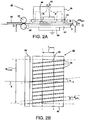
- Fig. 2A shows the side view of the corona treatment device according to an embodiment of the present invention.
- a cut sheet material 54 is transported by sheet transporting means through a transport path 48 in the direction indicated by arrow X along a corona unit 40.
- the transport path 48 has a height H, which is sufficient to accommodate the thickness of the transported cut sheet material. Note that the transport path height H in Fig. 2A is shown schematically and is typically in the range of 1 to 3 mm.
- the sheet transport means comprises a driving roller 58 and a free rotatable roller 57, which together form a transport pinch.
- the corona unit 40 comprises a body 46, a corona means comprising one corona electrode 42, and a plurality of sheet guide elements 44 (see Fig. 2B ).
- the plurality of sheet guide elements 44 is positioned between the corona electrode 42 and the transport path 48.
- Each of the plurality of sheet guide elements 44 provides a predetermined distance PD guid between the transport path 48 and the corona electrode 42.
- the predetermined distance PD guid in Fig. 2A is shown schematically and is typically in the range of about 1.5 mm.
- the sheet guide element 44 may be constituted of a ceramic material, such as aluminium oxide (Al 2 O 3 ), silicon nitride (Si 3 N 4 ) or silicon carbide (SiC).
- the corona unit further comprises a counter electrode 50.
- the counter electrode 50 is electrically grounded.
- the sheet transporting means comprises a sheet supporting surface 52 for supporting the sheet 54 during transport in the direction of the sheet transport path 48 along the corona electrode 42.
- An air flow indicated by arrows A is provided inside of the corona unit 40.
- the air flow removes air contaminations, which is generated between the corona electrode 42 and the counter electrode 50, and directs the contaminations towards an air pump device (not shown).
- the air pump device further contains a filter in order to remove the air contaminations, such as ozone, from the air flow.
- the sheet supporting surface 52 comprises an electrical insulating layer, for example a ceramic layer, such as a glass layer, or a polymeric layer.
- the electrical insulating layer arranged in between the counter electrode 50 and the transport path 48 provides that the surface treatment of the cut sheet material 54 during the corona discharge process of the corona means 42 towards the surface of the cut sheet material attains a certain treatment widening. This improves the uniformity and quality of the surface treatment of the cut sheet material 54.
- Fig. 2B shows a bottom view of the corona treatment device of the embodiment shown in Fig. 2A along the line II-II.
- the corona electrode 42 has a certain width W corona and length L corona over which a corona plasma treatment is applied.
- the corona plasma treatment length of the corona electrode in this embodiment is the same as the dimension of the corona electrode L corona in the direction of the sheet transport X.
- the cut sheet material is guided by the sheet guide elements 44 along the corona unit 40 in the direction indicated by arrow X.
- Each of the plurality of sheet guide elements 44 extend in a direction, the extending direction being arranged at an angle indicated by ⁇ with respect to the sheet transport direction X.
- a sheet guide element prohibits or reduces a surface treatment of the cut sheet material in the area where the sheet guide element covers the corona electrode 42.
- the distance between each of the plurality of guide elements is d guid . In an embodiment the distance d guid is such that a portion of the surface of the cut sheet at most contacts one of the plurality of the guide elements 44 when moving in the direction X along the corona unit 40 over the treatment length L corona of the corona electrode 42.
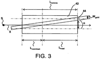
- Fig. 3 shows schematically an enlarged bottom view of an angle of a sheet guide element of a corona treatment device according to the present invention.
- the sheet guide element 44 has a certain width W guid and is arranged at the angle indicated by ⁇ with respect to the sheet transport direction X.
- the corona electrode 42 has a treatment length L corona over which a corona plasma treatment can be provided to a certain portion of a surface of a cut sheet material.
- the angle ⁇ is selected such that at most 20%, of the treatment length of the corona is covered by the sheet guide element 44. In case the width W guid of the sheet guide element 44 increases, or the treatment length L corona of the corona electrode 42 decreases, the angle ⁇ may be increased to ensure a sufficient surface treatment.
- the angle ⁇ is selected such that it is at least ⁇ (minimum) or higher.
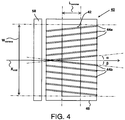
- Fig. 4 shows a bottom view of another embodiment of the corona treatment device.
- the cut sheet material is guided by the subset of the plurality of sheet guide elements 44a and the subset of the plurality of sheet guide elements 44b along the corona unit 40 in the direction indicated by arrow X.
- the subset of the plurality of guide elements 44a at one side of the line indicated by arrow X mid is arranged at an angle indicated by ⁇ with respect to the sheet transport direction X.
- the subset of the plurality of guide elements 44b at the other side of the line indicated by arrow X mid is arranged at an angle indicated by ⁇ with respect to the sheet transport direction X.
- a cut sheet is transported along the direction X.
- a cut sheet may be transported such that the side edges of the cut sheet move at the opposite of the line indicated by arrow X mid . As a result the two side edges of the cut sheet are both guided without disturbing the cut sheet transport.
- each cut sheet is moved at the line indicated by arrow X mid .
- the two side edges of a cut sheet material are located at either sides of the arrow X mid independently of the width of the cut sheet material.
- the subsets of plurality of guide elements 44a and 44b are arranged at both sides of the line X mid such that each of the plurality of guide elements is directed away from the respective side edge of a transported sheet in the direction of the sheet.
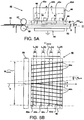
- Fig. 5A shows a side view of a corona treatment device according to an embodiment of the present invention.
- the corona unit 40 comprises four corona electrodes 42a, 42b, 42c, 42d which are arranged at a distance relative to each other along the sheet transport path 48.
- the corona electrodes 42a, 42b, 42c, 42d are arranged such that the air flow represented by arrows indicated with A can easily flow inside of the corona unit 40.
- the air flow removes air contaminations, which is generated between the plurality of corona electrodes 42a, 42b, 42c, 42d and the counter electrode 50, and directs the contaminations towards an air pump device (not shown).
- Fig. 5B shows a bottom view of the corona treatment device of the embodiment shown in Fig. 5A along the line II-II.
- the cut sheet material is guided by the subset of the plurality of sheet guide elements 44a and the subset of the plurality of sheet guide elements 44b along the corona unit 40 in the direction indicated by arrow X.
- the subset of the plurality of guide elements 44a is arranged at an angle indicated by ⁇ with respect to the sheet transport direction X.
- the subset of the plurality of guide elements 44b is arranged at an angle indicated by ⁇ with respect to the sheet transport direction X.
- the corona electrode 42a, 42b, 42c, 42d have a length L x (a), L x (b), L x (c), L x (d) over which it applies a corona plasma treatment to a portion of the surface of a cut sheet material.
- the treatment lengths of the corona electrodes 42a, 42b, 42c, 42d may be identical and may be different to each other.
- the plurality of corona electrodes 42a, 42b, 42c, 42d is arranged over a length L' corona in the direction of the sheet transport direction X.
- the total corona plasma treatment length is the sum of the respective treatment lengths L x (a), L x (b), L x (c), L x (d) of each corona electrode 42a, 42b, 42c, 42d.
- the distance d guid between neighboring sheet guide elements is such, that a portion of the surface of the cut sheet at most contacts one of the plurality of the guide elements 44 when moving in the direction X along the corona unit 40 over the length L' corona of the four corona electrodes 42a, 42b, 42c, 42d.
- the angle ⁇ and ⁇ are selected such that at most 20%, of the sum of the lengths L x (a), L x (b), L x (c), L x (d) of the plurality of corona electrodes 42a, 42b, 42c, 42d is covered by the sheet guide element 44.
- the angle ⁇ and ⁇ may be increased to ensure a sufficient surface treatment.
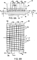
- Fig. 6A shows a side view of a corona treatment device according to an embodiment of the present invention.
- the corona unit 40 comprises four corona electrodes 42a, 42b, 42c, 42d, a plurality of sheet guide elements 44 (shown in fig. 6B ) and three supporting elements 62a, 62b and 62c.
- the supporting elements 62a, 62b, 62c are arranged substantially parallel to the corona electrodes 42a, 42b, 42c, 42d in between the four corona electrodes 42a, 42b, 42c, 42d.
- the supporting elements 62a, 62b, 62c are connected to the plurality of sheet guide elements 44. This provides a relatively simple and mechanically strong grid construction.
- connection to the supporting elements 62a, 62b, 62c provide a relatively short length d support between each supporting position of the plurality of sheet guide elements 44, thereby providing a relatively high stiffness to the sheet guide elements 44 in the direction perpendicular to the length d support .
- the sheet guide elements 44 have a height H guid , which is adjusted to be smaller than the predetermined distance PD guid and are arranged at a certain distance from the corona electrodes 42a, 42b, 42c, 42d. This has the advantage that the sheet guide elements 44 are less exposed to the electrical field generated by the corona electrodes 42a, 42b, 42c, 42d.
- the predetermined distance PD guid between the corona electrodes 42a, 42b, 42c, 42d and the transport path 48 is still accurately maintained, for example also during contact with the cut sheet material 54 during transport along the sheet guide elements 44.
- the at least one supporting element 62a, 62b, 62c are connected to each other by connecting elements 64a, 64b (shown in Fig. 6B ).
- the connecting elements 64a, 64b are fixed to the body 46.
- Fig. 6B shows a bottom view of the corona treatment device of the embodiment shown in Fig. 6A along the line II-II.
- the cut sheet material is guided by the subset of the plurality of sheet guide elements 44a and the subset of the plurality of sheet guide elements 44b along the corona unit 40 in the direction indicated by arrow X.
- the subset of the plurality of guide elements 44a is arranged at an angle indicated by ⁇ with respect to the sheet transport direction X.
- the subset of the plurality of guide elements 44b is arranged at an angle indicated by ⁇ with respect to the sheet transport direction X.
- Fig. 7 shows a side view of a sheet transporting means comprising a pressing foot for pressing a portion of the sheet onto a sheet supporting surface according to an embodiment of the invention.
- a cut sheet material 54 is transported by a sheet transporting means in the direction of a sheet transport path 48 indicated by arrow X along a corona unit 40.
- the sheet transport means comprises a driving roller 58 and a free rotatable roller 57, which together form a transport pinch.
- a pressing foot 74 is fixed to the axis 70 of the free rotatable roller 57 by clamp 76.
- a weight 72 is provided on the downstream side of the pressing foot 74, thereby providing a pressure indicated by arrow F onto a sheet supporting surface 52 near the sheet transport path 48.
- An airflow represented by arrows A is provided inside the transport path in order to remove air contamination, such as ozone gasses, from the corona device 40.
- the pressing foot 74 provides stiffness to the sheet 54 in the direction perpendicular to the sheet transport direction X. This enables an improved control over the transport direction of the sheet 54 along the corona unit 40, even in case the airflow is provided inside the transport path 48.
- Fig. 8A shows an enlarged side view of the construction of a sheet guide element according to an embodiment of the present invention.
- the sheet guide element 44 comprises three protrusions 84a, 84b and 84c.
- Each protrusion comprises a hole 85a, 85b, 85c.
- Each of the holes 85a, 85b, 85c may provide a space suitable to embrace a corona electrode 42 (not shown).
- the protrusion 84a, 84b and 84c is fixed at at least one side of the hole 85a, 85b, 85c to the corona electrode 42, the corona electrode 42 provides a support element for the sheet guide element 44.
- the sheet guide element 44 is constituted of a ceramic material, such as aluminium oxide (Al 2 O 3 ), silicon nitride (Si 3 N 4 ) or silicon carbide (SiC).
- the corona electrode 42 has substantially the same height as the height of the hole 85a - 85e.
- the distance d p between two protrusions 84a, 84b may be adjusted in order to provide better mechanical properties to the sheet guide element 44. In an embodiment the distance d p may be 0, whereby the protrusions 84a, 84b may be elements of a single protrusion comprising the two holes 85a, 85b.
- the holes 85a, 85b, 85c may be aligned with the upper side 44' of the extending sheet guide element (hole 85a, 85c) or may be offset with respect to the upper side 44' of the extending sheet guide element (hole 85b).
- the hole may be rectangular, but may also have any other shape.
- the predetermined distance PD guid between the corona electrode 42 and the paper transport path 48, i.e. the lower side 44" of the sheet guide element, is aligned with the upper side 44' in case the lower side of the corona electrode 42 is aligned with the upper side 44' of the sheet guide element 44.
- the lower side of the corona electrode may be arranged offset from the upper side 44' of the sheet guide element 44, thereby adjusting the predetermined distance (not shown).
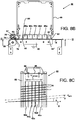
- Fig. 8B shows a side view of the construction of a corona treatment device according to an embodiment of the present invention.
- a cut sheet material is transported by a sheet transporting means in the direction of a sheet transport path indicated by arrow X along a corona unit 40.
- the sheet transport means comprises a driving roller 58 and a free rotatable roller 57, which together form a transport pinch.
- a pressing foot 74 is fixed to the axis of the free rotatable roller 57 by clamp 76.
- a weight 72 is provided on the downstream side of the pressing foot, thereby providing a pressure onto a sheet supporting surface 50 near the sheet transport path.
- An airflow (not shown) is provided inside the transport path in order to remove air contamination, such as ozone gasses, from the corona device 40.
- the corona unit 40 comprises a body 46, five corona electrodes 42a, 42b, 42c, 42d, 42e (shown in Fig. 8c ), a plurality of sheet guide elements 44 (shown in Fig. 8C ) each comprising a protrusion 84.
- the protrusion 84 comprises five holes 85a - 85e. Each of the five holes embraces a corona electrode 42a - 42e (shown in Fig. 8C ).
- the body 46 comprises two body elements 82 for holding the plurality of sheet guide elements 44. The two body elements 82 extend in a direction parallel to the corona electrodes 42a - 42e and are both electrical insulating.
- the sheet guide elements 44 provide a predetermined distance PD guid (not shown) between the corona electrodes 42a - 42e and the transport path, which is typically in the range of about 1.5 mm.
- the sheet guide elements 44 is constituted of a ceramic material, such as aluminium oxide (Al 2 O 3 ), silicon nitride (Si 3 N 4 ) or silicon carbide (SiC).
- the holes 85a - 85e are arranged offset from the upper side of the sheet guide element 44'.
- the parts of the sheet guide elements 44 between the holes 85a - 85e and the lower side of the sheet guide element 44" have a smaller height than the height of the other parts of the sheet guide elements 44.
- the sheet guide elements 44 are connected to each of the five corona electrodes 42 by way of at least one side of each of the holes 85a - 85e of the protrusion 84.
- each of the five corona electrodes 42 has the same height as the height of the corresponding holes 85a - 85e.
- the protrusion 84 together with the connection to the corona electrodes 42a - 42e provides a relatively high stiffness to the sheet guide elements 44 in the direction perpendicular to the length of the sheet guide element.
- the sheet supporting surface 50 is a RVS plate, which is electrically grounded, and as such also serves as a counter electrode.
- Fig. 8C shows a partial bottom view of the construction of the corona treatment device of the embodiment shown in Fig 8B along the line II-II.
- the body 46 comprises the two body elements 82 for holding the plurality of sheet guide elements 44.
- the body 46 further comprises at each end a handle 86 for handling the corona unit 40.
- Each of the plurality of guide elements 44 has a width W guid of about 1 mm and extend in a direction, the direction being arranged at an angle indicated by a with respect to the sheet transport direction X.
- a sheet guide element prohibits or reduces a surface treatment of the cut sheet material in the area where the sheet guide element covers the corona electrodes 42a-42e.
- the corona plasma treatment length in this embodiment of each of the corona electrodes 42a-42e is 10 mm.
- the sum of the corona plasma treatment length L corona is 50 mm.
- the total length L' corona of the five corona electrodes 42a-42e being about 55 mm is determined by the sum of the corona plasma treatment length plus the distances between the five corona electrodes, and is in this embodiment not equal to the corona plasma treatment length L corona .
- each of the plurality of sheet guide elements d guid is 10 mm.
- the distance d guid between neighboring sheet guide elements is selected, such that a portion of the surface of the cut sheet at most contacts one of the plurality of the guide elements 44 when moving in the direction X along the corona unit 40 over the length L' corona of the five corona electrodes 42a-42e.
- the angle ⁇ in this embodiment is selected in the range 6 to 10 degrees.
- the lower value of the angle corresponds to the width of the sheet guide element 44 and the treatment length of the corona L corona .
- the upper value of the angle corresponds to the distance d guid between neighboring sheet guide elements 44 and the total length L' corona of the five corona electrodes 42a-42e.
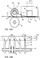
- Fig. 9A shows a side view of the construction a corona treatment device according to an embodiment of the present invention.
- a counter electrode unit 61 is provided below the transport path 48 comprising a counter electrode 50.
- the counter electrode 50 is a cylindrical electrode being rotatable around axial axis 59 and comprising an electrical insulating layer 60 at the outer surface of the counter electrode 50.
- the counter electrode 50 is electrically grounded.
- the electrical insulating layer 60 provides that a corona discharging treatment process directing from the corona element 42 to the counter electrode 50 attains a certain discharging treatment widening, thereby improving the quality of the surface treatment of a sheet.
- the counter electrode is rotated in the direction R around axial axis 59. Air is provided in the direction C in order to cool the surface of the counter electrode 50.
- a sheet supporting surface 52 is arranged in between the counter electrode 50 and the transport path 48 in order to support a cut sheet 54 during transport along the corona unit 40.
- Fig. 9B shows a bottom view of the corona treatment device of the embodiment shown in Fig. 9A along the line III-III.
- the treatment length of the corona electrode 42 in this embodiment is 15 mm and the diameter D counter of the counter electrode 50 is 100 mm.
- the sheet supporting surface 52 comprises a plurality of sheet supporting elements 92.
- the sheet supporting elements 92 extend in a direction, having an angle ⁇ with respect to the sheet transport direction X.
- the angle ⁇ may be zero, as the sheet supporting elements 92 at the lower side of the transport path 48 do not prohibit a surface corona plasma treatment of the cut sheet by the corona electrode 42 at the upper side of the transport path 48.
- the angle ⁇ may be selected larger than zero in order to provide a controlled guiding of the lower side of the cut sheet along the counter electrode 50.
- the sheet supporting elements may be constituted by wires, for example wires comprising a perfluoroalkylene polymer.
- Fig. 10A and 10B show an embodiment of the present invention wherein the sheet guide element is a portion of a pressing foot of the sheet transporting means.
- Fig. 10A shows a side view of a sheet transporting means comprising the pressing foot 174 for pressing a portion of the sheet 54 onto a sheet supporting surface 52.
- the cut sheet material 54 is transported by a sheet transporting means in the direction of a sheet transport path 48 indicated by arrow X along a corona unit 40.
- the sheet transport means comprises a driving roller 58 and a free rotatable roller 57, which together form a transport pinch.
- the pressing foot 174 is fixed to the axis 170 of the free rotatable roller 57 by clamp 176.
- the pressing foot 174 comprises a first portion 175, which extends in the direction of the sheet transport path 48 up to the corona electrode 42 of the corona unit 40.
- the pressing foot 174 further comprises a second portion 178, which extends between the corona electrode 42 and the transport path 48 over at least a part of the corona plasma treatment length L corona .
- a bottom view is shown of the sheet transporting means and the pressing foot shown in Fig. 10A along the line II-II.
- a number of pressing foots 174 are shown.
- Each of the pressing foot 174 is connected to the axis 170 of the free rotatable roller 57.
- the first portion 175 of the pressing foot 174 extends in the transport direction x of the sheet transport path 48 up to the corona electrode 42 of the corona unit 40.
- the second portion 178 of the pressing foot 174 extends in a direction which is arranged at an angle ⁇ with respect to the transport direction x of the sheet transport path 48.
- the angle ⁇ is suitably selected such that the second portion 178 of the pressing foot only partially covers a corona plasma treatment length L corona of the corona electrode 42.
- the second portion 178 of the pressing foot covers at most 20% of the corona plasma treatment length L corona of the corona electrode 42 in the transport direction x.
- the corona electrode 42 provides a corona plasma treatment of the cut sheet media over the width of the corona electrode 42 (i.e. perpendicular to the transport direction x) which is uniform and of high quality.
- the terms and phrases used herein are not intended to be limiting; but rather, to provide an understandable description of the invention.
- the terms "a” or “an”, as used herein, are defined as one or more than one.
- the term plurality, as used herein, is defined as two or more than two.
- the term another, as used herein, is defined as at least a second or more.
- the terms including and/or having, as used herein, are defined as comprising (i.e., open language).
- the term coupled, as used herein, is defined as connected, although not necessarily directly.
Landscapes
- Physics & Mathematics (AREA)
- Engineering & Computer Science (AREA)
- Plasma & Fusion (AREA)
- Spectroscopy & Molecular Physics (AREA)
- Treatments Of Macromolecular Shaped Articles (AREA)
- Supply, Installation And Extraction Of Printed Sheets Or Plates (AREA)
- Electrostatic Charge, Transfer And Separation In Electrography (AREA)
- Ink Jet (AREA)
- Feeding Of Articles By Means Other Than Belts Or Rollers (AREA)
Claims (14)
- Koronabehandlungsvorrichtung (40) zur Behandlung eines geschnittenen Bogenmaterials (54), welche Koronabehandlungsvorrichtung aufweist:- eine Koronaeinrichtung zum Anwenden einer Korona-Plasmabehandlung auf eine Oberfläche eines Bogens (54), wobei die Koronaeinrichtung eine Koronaelektrode (42, 42a-e) und eine Gegenelektrode (50) aufweist, die in enger Nachbarschaft zueinander angeordnet sind,- eine Bogentransporteinrichtung (57, 58) zum Transportieren des Bogens (54) in Richtung eines Transportpfades (48), wobei der Transportpfad des geschnittenen Bogenmaterials durch die Koronaeinrichtung hindurch und zwischen der Koronaelektrode und der Gegenelektrode verläuft und- mehrere Bogenführungselemente (44) zum Führen des Bogens entlang der Koronaelektrode (42, 42a-e), wobei die mehreren Bogenführungselemente (44) zwischen der Koronaelektrode (42,42a-e) und dem Transportpfad (48) angeordnet sind und dadurch einen vorbestimmten Abstand (PDguid) zwischen dem Transportpfad und der Koronaelektrode schaffen,wobei die mehreren Bogenführungselemente (44) wenigstens ein erstes Bogenführungselement (44, 44a) aufweisen, das sich in einer Richtung unter einem ersten Winkel (α) in einer Ebene der Bogentransportrichtung in Bezug auf die Bogentransportrichtung (X) erstreckt,
dadurch gekennzeichnet, dass der erste Winkel (α) in der Ebene der Bogentransportrichtung des Bogenführungselements (44, 44a) zusammen mit einer Breite des Bogenführungselements Wguid definiert, welcher Teil einer Behandlungslänge der Koronaeinrichtung Lcorona in der Bogentransportrichtung (X) durch das Bogenführungselement (44, 44a) in der Ebene der Bogentransportrichtung (X) abgedeckt wird, und wobei höchstens 20% der Behandlungslänge der Koronaeinrichtung Lcorona abgedeckt werden. - Koronabehandlungsvorrichtung nach Anspruch 1, bei der der vorbestimmte Abstand (PDguid) im Bereich von 1 mm bis 3 mm liegt.
- Koronabehandlungsvorrichtung nach Anspruch 1, bei der jedes der mehreren Bogenführungselemente (44) ein keramisches Material aufweist.
- Koronabehandlungsvorrichtung nach Anspruch 1, bei der die Breite des Bogenführungselements Wguid im Bereich von 0,3 mm bis 1 mm liegt und die Behandlungslänge der Koronaeinrichtung wenigstens 10 mm beträgt.
- Koronabehandlungsvorrichtung nach einem der vorstehenden Ansprüche, bei der die mehreren Bogenführungselemente (44) ein zweites Bogenführungselement (44b) aufweisen, das sich in einer Richtung unter einem zweiten Winkel (β) in der Ebene der Bogentransportrichtung (X) in Bezug auf die Bogentransportrichtung (X) erstreckt, wobei der zweite Winkel von dem ersten Winkel verschieden ist.
- Koronabehandlungsvorrichtung nach Anspruch 5, bei der der zweite Winkel (β) dem ersten Winkel (a) in der Ebene der Bogentransportrichtung in Bezug auf die Bogentransportrichtung (X) entgegen gerichtet ist.
- Koronabehandlungsvorrichtung nach einem der vorstehenden Ansprüche, bei der wenigstens eines der mehreren Bogenführungselemente (44) durch wenigstens ein Tragelement (62a-c; 42a-c) gehalten ist, wobei das wenigstens eine Tragelement (62a-c) im wesentlichen parallel zu der Koronaelektrode (42a-c) angeordnet ist, wobei insbesondere wenigstens eines der mehreren Bogenführungselemente (44) durch die Koronaelektrode (42a-c) gehalten ist, die das Tragelement bildet.
- Koronabehandlungsvorrichtung nach einem der vorstehenden Ansprüche, bei der wenigstens eines der Bogenführungselemente (44) durch einen Draht gebildet wird, wobei der Draht ein Perfluoralkylenpolymer aufweist, wobei der Draht insbesondere eine Oberflächebeschichtung aufweist, die ein Perfluoralkylenpolymer enthält.
- Koronabehandlungsvorrichtung nach einem der vorstehenden Ansprüche, bei der die Bogentransporteinrichtung weiterhin eine Bogenabstützfläche (52) zur Abstützung des Bogens (54) während des Transport des Bogens entlang der Koronaeinrichtung (42, 50) aufweist, wobei die Abstützfläche (52) zwischen dem Transportpfad (48) und der Gegenelektrode (50) angeordnet ist.
- Koronabehandlungsvorrichtung nach Anspruch 9, bei der die Bogentransporteinrichtung weiterhin eine Bogeneinzugsklemmrolle (57) aufweist, wobei die Bogentransporteinrichtung weiterhin ein Andruckfüßchen (74, 174) zum Andrücken eines Teils des Bogens (54) auf die Bogenabstützfläche (52) aufweist, wobei das Andruckfüßchen (74, 174) in Bezug auf die Bogentransportrichtung (X) stromabwärts der Bogeneinzugsklemmrolle (57) angeordnet ist.
- Koronabehandlungsvorrichtung nach Anspruch 10, bei der das Bogenführungselement (178) ein Teil des Andruckfüßchens (174) der Bogentransporteinrichtung ist.
- Koronabehandlungsvorrichtung nach einem der vorstehenden Ansprüche, bei der die Koronaeinrichtung weiterhin eine elektrische Isolationsschicht (52, 60) aufweist, die zwischen dem Transportpfad und der Gegenelektrode angeordnet ist.
- Koronabehandlungsvorrichtung nach Anspruch 1, bei der die Gegenelektrode eine zylindrische Elektrode (50) ist, die um ihre axiale Achse (59) drehbar ist, wobei die Gegenelektrode wahlweise eine elektrisch isolierende Schicht (60) an der äußeren Oberfläche der Gegenelektrode aufweist.
- Druckersystem zum Verarbeiten eines geschnittenen Bogenmaterials, wobei das Druckersystem die Koronabehandlungsvorrichtung nach Anspruch 1 bis 13 zur Plasmabehandlung einer Oberfläche des geschnittenen Bogenmaterials (54), wenigstens eine Markierungsstation (1) zum Anbringen eines Markierungsmaterials auf dem geschnittenen Bogenmaterial, eine Einzugsstation (4) für die geschnittenen Bögen, und eine Ausgabestation (5) für die geschnittenen Bögen aufweist.
Priority Applications (1)
| Application Number | Priority Date | Filing Date | Title |
|---|---|---|---|
| EP13700552.6A EP2802455B1 (de) | 2012-01-13 | 2013-01-11 | Vorrichtung zur behandlung der korona |
Applications Claiming Priority (3)
| Application Number | Priority Date | Filing Date | Title |
|---|---|---|---|
| EP12151049 | 2012-01-13 | ||
| PCT/EP2013/050483 WO2013104753A2 (en) | 2012-01-13 | 2013-01-11 | Corona treatment device |
| EP13700552.6A EP2802455B1 (de) | 2012-01-13 | 2013-01-11 | Vorrichtung zur behandlung der korona |
Publications (2)
| Publication Number | Publication Date |
|---|---|
| EP2802455A2 EP2802455A2 (de) | 2014-11-19 |
| EP2802455B1 true EP2802455B1 (de) | 2016-04-27 |
Family
ID=47563495
Family Applications (1)
| Application Number | Title | Priority Date | Filing Date |
|---|---|---|---|
| EP13700552.6A Active EP2802455B1 (de) | 2012-01-13 | 2013-01-11 | Vorrichtung zur behandlung der korona |
Country Status (4)
| Country | Link |
|---|---|
| US (1) | US20140320575A1 (de) |
| EP (1) | EP2802455B1 (de) |
| JP (1) | JP2015510458A (de) |
| WO (1) | WO2013104753A2 (de) |
Families Citing this family (9)
| Publication number | Priority date | Publication date | Assignee | Title |
|---|---|---|---|---|
| DK177766B3 (da) * | 2013-03-19 | 2018-04-30 | Tresu As | Enhed og fremgangsmåde til koronabehandling |
| JP2015085527A (ja) * | 2013-10-28 | 2015-05-07 | 株式会社リコー | 改質装置、画像形成装置、画像形成システム、及び印刷物の製造方法 |
| EP3129230B1 (de) | 2014-04-11 | 2018-02-28 | OCE-Technologies B.V. | Tintenstrahldrucker umfassend eine plasmaerzeugende vorrichtung, plasmaerzeugende vorrichtung dazu, und verfahren dazu |
| EP3025991B1 (de) * | 2014-11-27 | 2017-07-26 | OCE-Technologies B.V. | Verfahren und bogentransportanordnung zur übertragung eines bogens zwischen zwei förderern |
| DE102016109044B3 (de) | 2016-05-17 | 2017-07-06 | Leonhard Kurz Stiftung & Co. Kg | Vorrichtung zur Oberflächenbehandlung eines Substrats |
| JP2018099871A (ja) * | 2016-11-18 | 2018-06-28 | イマジニアリング株式会社 | 印刷装置 |
| JP7110018B2 (ja) * | 2018-07-19 | 2022-08-01 | サカタインクス株式会社 | プラズマ処理インクジェット印刷装置 |
| WO2023074632A1 (ja) * | 2021-10-29 | 2023-05-04 | 株式会社デュプロ | 放電処理装置及びシート材処理システム |
| CN115847795B (zh) * | 2022-12-30 | 2023-09-15 | 常州奥福电子设备有限公司 | 一种电晕间隙均匀的薄膜电晕机 |
Citations (1)
| Publication number | Priority date | Publication date | Assignee | Title |
|---|---|---|---|---|
| DE10050301A1 (de) * | 2000-10-10 | 2002-04-25 | Windmoeller & Hoelscher | Verfahren zum Ablösen einer gasförmigen laminaren Grenzschicht von schnelllaufendem Material |
Family Cites Families (4)
| Publication number | Priority date | Publication date | Assignee | Title |
|---|---|---|---|---|
| JPH0617127Y2 (ja) * | 1987-11-25 | 1994-05-02 | 三田工業株式会社 | コロナ放電器 |
| US5527123A (en) * | 1995-02-28 | 1996-06-18 | Hewlett-Packard Company | Media handling in an ink-jet printer |
| US6941606B2 (en) * | 2002-07-02 | 2005-09-13 | Electrostatics, Incorporated | Sheet and web cleaner on suction hood |
| JP2009279796A (ja) * | 2008-05-20 | 2009-12-03 | Tohoku Ricoh Co Ltd | インクジェット記録方法及びインクジェット記録装置 |
-
2013
- 2013-01-11 WO PCT/EP2013/050483 patent/WO2013104753A2/en active Application Filing
- 2013-01-11 EP EP13700552.6A patent/EP2802455B1/de active Active
- 2013-01-11 JP JP2014551626A patent/JP2015510458A/ja not_active Withdrawn
-
2014
- 2014-07-11 US US14/329,724 patent/US20140320575A1/en not_active Abandoned
Patent Citations (1)
| Publication number | Priority date | Publication date | Assignee | Title |
|---|---|---|---|---|
| DE10050301A1 (de) * | 2000-10-10 | 2002-04-25 | Windmoeller & Hoelscher | Verfahren zum Ablösen einer gasförmigen laminaren Grenzschicht von schnelllaufendem Material |
Also Published As
| Publication number | Publication date |
|---|---|
| JP2015510458A (ja) | 2015-04-09 |
| WO2013104753A2 (en) | 2013-07-18 |
| WO2013104753A3 (en) | 2013-11-21 |
| EP2802455A2 (de) | 2014-11-19 |
| US20140320575A1 (en) | 2014-10-30 |
Similar Documents
| Publication | Publication Date | Title |
|---|---|---|
| EP2802455B1 (de) | Vorrichtung zur behandlung der korona | |
| US7216968B2 (en) | Media electrostatic hold down and conductive heating assembly | |
| US9268286B2 (en) | Printing arrangement for two-sided printing on a recording medium and printing method | |
| US7029111B2 (en) | Unit for the continuous production of printed textile strips, in particular printed label strips | |
| US8628188B2 (en) | Drying apparatus and printing apparatus | |
| US9994049B1 (en) | Adjustable path length of print media in a dryer of a printing system | |
| US20120224003A1 (en) | Sheet processing device | |
| US8408270B2 (en) | Apparatuses useful in printing, fixing devices and methods of stripping substrates from surfaces in apparatuses useful in printing | |
| US9707778B2 (en) | Belt on belt sheet transport system for a printing system | |
| JP6221211B2 (ja) | 誘電体バリア放電発生装置とシート材改質装置、画像形成装置及び印刷物の生産方法 | |
| US6997549B2 (en) | Media hold down system | |
| US8840105B1 (en) | Recharger to restore electrostatic holding force | |
| JP2017223384A (ja) | 乾燥装置及び液体定着装置 | |
| US10723152B2 (en) | Electric field generating transport member | |
| JP2006212929A (ja) | インクジェット記録装置 | |
| US9776431B2 (en) | Medium conveying device and image recording apparatus | |
| US20150036155A1 (en) | Charger providing non-uniform electrostatic holding force | |
| CN111907213B (zh) | 用于减少由喷墨打印机打印的基片中的卷曲的系统和装置 | |
| US9809039B2 (en) | Plasma generating device | |
| US8844926B1 (en) | Controlling recharging to restore electrostatic holding force | |
| JP2007331239A (ja) | 液滴吐出装置 | |
| JP6344280B2 (ja) | 記録媒体処理装置、画像形成装置及び画像形成システム | |
| US10493777B1 (en) | Electric field generating transport member | |
| CN115151423B (zh) | 具有电荷加载装置的印刷机 | |
| JP2006219291A (ja) | 用紙搬送装置及び画像形成装置 |
Legal Events
| Date | Code | Title | Description |
|---|---|---|---|
| PUAI | Public reference made under article 153(3) epc to a published international application that has entered the european phase |
Free format text: ORIGINAL CODE: 0009012 |
|
| 17P | Request for examination filed |
Effective date: 20140813 |
|
| AK | Designated contracting states |
Kind code of ref document: A2 Designated state(s): AL AT BE BG CH CY CZ DE DK EE ES FI FR GB GR HR HU IE IS IT LI LT LU LV MC MK MT NL NO PL PT RO RS SE SI SK SM TR |
|
| DAX | Request for extension of the european patent (deleted) | ||
| 17Q | First examination report despatched |
Effective date: 20150608 |
|
| GRAP | Despatch of communication of intention to grant a patent |
Free format text: ORIGINAL CODE: EPIDOSNIGR1 |
|
| INTG | Intention to grant announced |
Effective date: 20151110 |
|
| GRAS | Grant fee paid |
Free format text: ORIGINAL CODE: EPIDOSNIGR3 |
|
| GRAA | (expected) grant |
Free format text: ORIGINAL CODE: 0009210 |
|
| AK | Designated contracting states |
Kind code of ref document: B1 Designated state(s): AL AT BE BG CH CY CZ DE DK EE ES FI FR GB GR HR HU IE IS IT LI LT LU LV MC MK MT NL NO PL PT RO RS SE SI SK SM TR |
|
| REG | Reference to a national code |
Ref country code: GB Ref legal event code: FG4D |
|
| REG | Reference to a national code |
Ref country code: CH Ref legal event code: EP |
|
| REG | Reference to a national code |
Ref country code: AT Ref legal event code: REF Ref document number: 794279 Country of ref document: AT Kind code of ref document: T Effective date: 20160515 |
|
| REG | Reference to a national code |
Ref country code: IE Ref legal event code: FG4D |
|
| REG | Reference to a national code |
Ref country code: DE Ref legal event code: R096 Ref document number: 602013006984 Country of ref document: DE |
|
| REG | Reference to a national code |
Ref country code: NL Ref legal event code: FP |
|
| REG | Reference to a national code |
Ref country code: LT Ref legal event code: MG4D |
|
| REG | Reference to a national code |
Ref country code: AT Ref legal event code: MK05 Ref document number: 794279 Country of ref document: AT Kind code of ref document: T Effective date: 20160427 |
|
| PG25 | Lapsed in a contracting state [announced via postgrant information from national office to epo] |
Ref country code: NO Free format text: LAPSE BECAUSE OF FAILURE TO SUBMIT A TRANSLATION OF THE DESCRIPTION OR TO PAY THE FEE WITHIN THE PRESCRIBED TIME-LIMIT Effective date: 20160727 Ref country code: FI Free format text: LAPSE BECAUSE OF FAILURE TO SUBMIT A TRANSLATION OF THE DESCRIPTION OR TO PAY THE FEE WITHIN THE PRESCRIBED TIME-LIMIT Effective date: 20160427 Ref country code: LT Free format text: LAPSE BECAUSE OF FAILURE TO SUBMIT A TRANSLATION OF THE DESCRIPTION OR TO PAY THE FEE WITHIN THE PRESCRIBED TIME-LIMIT Effective date: 20160427 Ref country code: PL Free format text: LAPSE BECAUSE OF FAILURE TO SUBMIT A TRANSLATION OF THE DESCRIPTION OR TO PAY THE FEE WITHIN THE PRESCRIBED TIME-LIMIT Effective date: 20160427 |
|
| PG25 | Lapsed in a contracting state [announced via postgrant information from national office to epo] |
Ref country code: ES Free format text: LAPSE BECAUSE OF FAILURE TO SUBMIT A TRANSLATION OF THE DESCRIPTION OR TO PAY THE FEE WITHIN THE PRESCRIBED TIME-LIMIT Effective date: 20160427 Ref country code: GR Free format text: LAPSE BECAUSE OF FAILURE TO SUBMIT A TRANSLATION OF THE DESCRIPTION OR TO PAY THE FEE WITHIN THE PRESCRIBED TIME-LIMIT Effective date: 20160728 Ref country code: SE Free format text: LAPSE BECAUSE OF FAILURE TO SUBMIT A TRANSLATION OF THE DESCRIPTION OR TO PAY THE FEE WITHIN THE PRESCRIBED TIME-LIMIT Effective date: 20160427 Ref country code: HR Free format text: LAPSE BECAUSE OF FAILURE TO SUBMIT A TRANSLATION OF THE DESCRIPTION OR TO PAY THE FEE WITHIN THE PRESCRIBED TIME-LIMIT Effective date: 20160427 Ref country code: PT Free format text: LAPSE BECAUSE OF FAILURE TO SUBMIT A TRANSLATION OF THE DESCRIPTION OR TO PAY THE FEE WITHIN THE PRESCRIBED TIME-LIMIT Effective date: 20160829 Ref country code: LV Free format text: LAPSE BECAUSE OF FAILURE TO SUBMIT A TRANSLATION OF THE DESCRIPTION OR TO PAY THE FEE WITHIN THE PRESCRIBED TIME-LIMIT Effective date: 20160427 Ref country code: AT Free format text: LAPSE BECAUSE OF FAILURE TO SUBMIT A TRANSLATION OF THE DESCRIPTION OR TO PAY THE FEE WITHIN THE PRESCRIBED TIME-LIMIT Effective date: 20160427 Ref country code: RS Free format text: LAPSE BECAUSE OF FAILURE TO SUBMIT A TRANSLATION OF THE DESCRIPTION OR TO PAY THE FEE WITHIN THE PRESCRIBED TIME-LIMIT Effective date: 20160427 |
|
| PG25 | Lapsed in a contracting state [announced via postgrant information from national office to epo] |
Ref country code: BE Free format text: LAPSE BECAUSE OF FAILURE TO SUBMIT A TRANSLATION OF THE DESCRIPTION OR TO PAY THE FEE WITHIN THE PRESCRIBED TIME-LIMIT Effective date: 20160427 Ref country code: IT Free format text: LAPSE BECAUSE OF FAILURE TO SUBMIT A TRANSLATION OF THE DESCRIPTION OR TO PAY THE FEE WITHIN THE PRESCRIBED TIME-LIMIT Effective date: 20160427 |
|
| REG | Reference to a national code |
Ref country code: FR Ref legal event code: PLFP Year of fee payment: 5 |
|
| REG | Reference to a national code |
Ref country code: DE Ref legal event code: R097 Ref document number: 602013006984 Country of ref document: DE |
|
| PG25 | Lapsed in a contracting state [announced via postgrant information from national office to epo] |
Ref country code: DK Free format text: LAPSE BECAUSE OF FAILURE TO SUBMIT A TRANSLATION OF THE DESCRIPTION OR TO PAY THE FEE WITHIN THE PRESCRIBED TIME-LIMIT Effective date: 20160427 Ref country code: CZ Free format text: LAPSE BECAUSE OF FAILURE TO SUBMIT A TRANSLATION OF THE DESCRIPTION OR TO PAY THE FEE WITHIN THE PRESCRIBED TIME-LIMIT Effective date: 20160427 Ref country code: RO Free format text: LAPSE BECAUSE OF FAILURE TO SUBMIT A TRANSLATION OF THE DESCRIPTION OR TO PAY THE FEE WITHIN THE PRESCRIBED TIME-LIMIT Effective date: 20160427 Ref country code: SK Free format text: LAPSE BECAUSE OF FAILURE TO SUBMIT A TRANSLATION OF THE DESCRIPTION OR TO PAY THE FEE WITHIN THE PRESCRIBED TIME-LIMIT Effective date: 20160427 Ref country code: EE Free format text: LAPSE BECAUSE OF FAILURE TO SUBMIT A TRANSLATION OF THE DESCRIPTION OR TO PAY THE FEE WITHIN THE PRESCRIBED TIME-LIMIT Effective date: 20160427 |
|
| PG25 | Lapsed in a contracting state [announced via postgrant information from national office to epo] |
Ref country code: SM Free format text: LAPSE BECAUSE OF FAILURE TO SUBMIT A TRANSLATION OF THE DESCRIPTION OR TO PAY THE FEE WITHIN THE PRESCRIBED TIME-LIMIT Effective date: 20160427 |
|
| PLBE | No opposition filed within time limit |
Free format text: ORIGINAL CODE: 0009261 |
|
| STAA | Information on the status of an ep patent application or granted ep patent |
Free format text: STATUS: NO OPPOSITION FILED WITHIN TIME LIMIT |
|
| 26N | No opposition filed |
Effective date: 20170130 |
|
| PG25 | Lapsed in a contracting state [announced via postgrant information from national office to epo] |
Ref country code: SI Free format text: LAPSE BECAUSE OF FAILURE TO SUBMIT A TRANSLATION OF THE DESCRIPTION OR TO PAY THE FEE WITHIN THE PRESCRIBED TIME-LIMIT Effective date: 20160427 |
|
| REG | Reference to a national code |
Ref country code: CH Ref legal event code: PL |
|
| PG25 | Lapsed in a contracting state [announced via postgrant information from national office to epo] |
Ref country code: MC Free format text: LAPSE BECAUSE OF FAILURE TO SUBMIT A TRANSLATION OF THE DESCRIPTION OR TO PAY THE FEE WITHIN THE PRESCRIBED TIME-LIMIT Effective date: 20160427 |
|
| PG25 | Lapsed in a contracting state [announced via postgrant information from national office to epo] |
Ref country code: LI Free format text: LAPSE BECAUSE OF NON-PAYMENT OF DUE FEES Effective date: 20170131 Ref country code: CH Free format text: LAPSE BECAUSE OF NON-PAYMENT OF DUE FEES Effective date: 20170131 |
|
| REG | Reference to a national code |
Ref country code: IE Ref legal event code: MM4A |
|
| PG25 | Lapsed in a contracting state [announced via postgrant information from national office to epo] |
Ref country code: LU Free format text: LAPSE BECAUSE OF NON-PAYMENT OF DUE FEES Effective date: 20170111 |
|
| REG | Reference to a national code |
Ref country code: FR Ref legal event code: PLFP Year of fee payment: 6 |
|
| PG25 | Lapsed in a contracting state [announced via postgrant information from national office to epo] |
Ref country code: IE Free format text: LAPSE BECAUSE OF NON-PAYMENT OF DUE FEES Effective date: 20170111 |
|
| PG25 | Lapsed in a contracting state [announced via postgrant information from national office to epo] |
Ref country code: MT Free format text: LAPSE BECAUSE OF NON-PAYMENT OF DUE FEES Effective date: 20170111 |
|
| PG25 | Lapsed in a contracting state [announced via postgrant information from national office to epo] |
Ref country code: AL Free format text: LAPSE BECAUSE OF FAILURE TO SUBMIT A TRANSLATION OF THE DESCRIPTION OR TO PAY THE FEE WITHIN THE PRESCRIBED TIME-LIMIT Effective date: 20160427 |
|
| PG25 | Lapsed in a contracting state [announced via postgrant information from national office to epo] |
Ref country code: HU Free format text: LAPSE BECAUSE OF FAILURE TO SUBMIT A TRANSLATION OF THE DESCRIPTION OR TO PAY THE FEE WITHIN THE PRESCRIBED TIME-LIMIT; INVALID AB INITIO Effective date: 20130111 |
|
| PG25 | Lapsed in a contracting state [announced via postgrant information from national office to epo] |
Ref country code: BG Free format text: LAPSE BECAUSE OF FAILURE TO SUBMIT A TRANSLATION OF THE DESCRIPTION OR TO PAY THE FEE WITHIN THE PRESCRIBED TIME-LIMIT Effective date: 20160427 |
|
| PG25 | Lapsed in a contracting state [announced via postgrant information from national office to epo] |
Ref country code: CY Free format text: LAPSE BECAUSE OF FAILURE TO SUBMIT A TRANSLATION OF THE DESCRIPTION OR TO PAY THE FEE WITHIN THE PRESCRIBED TIME-LIMIT Effective date: 20160427 |
|
| PG25 | Lapsed in a contracting state [announced via postgrant information from national office to epo] |
Ref country code: MK Free format text: LAPSE BECAUSE OF FAILURE TO SUBMIT A TRANSLATION OF THE DESCRIPTION OR TO PAY THE FEE WITHIN THE PRESCRIBED TIME-LIMIT Effective date: 20160427 |
|
| PG25 | Lapsed in a contracting state [announced via postgrant information from national office to epo] |
Ref country code: TR Free format text: LAPSE BECAUSE OF FAILURE TO SUBMIT A TRANSLATION OF THE DESCRIPTION OR TO PAY THE FEE WITHIN THE PRESCRIBED TIME-LIMIT Effective date: 20160427 |
|
| PG25 | Lapsed in a contracting state [announced via postgrant information from national office to epo] |
Ref country code: IS Free format text: LAPSE BECAUSE OF FAILURE TO SUBMIT A TRANSLATION OF THE DESCRIPTION OR TO PAY THE FEE WITHIN THE PRESCRIBED TIME-LIMIT Effective date: 20160827 |
|
| PGFP | Annual fee paid to national office [announced via postgrant information from national office to epo] |
Ref country code: FR Payment date: 20230124 Year of fee payment: 11 |
|
| PGFP | Annual fee paid to national office [announced via postgrant information from national office to epo] |
Ref country code: NL Payment date: 20231214 Year of fee payment: 12 |
|
| PGFP | Annual fee paid to national office [announced via postgrant information from national office to epo] |
Ref country code: DE Payment date: 20240119 Year of fee payment: 12 Ref country code: GB Payment date: 20240123 Year of fee payment: 12 |