EP3452131B1 - Systeme und verfahren zum betrieb von unterdruckquellen in unterdrucktherapiesystemen - Google Patents
Systeme und verfahren zum betrieb von unterdruckquellen in unterdrucktherapiesystemen Download PDFInfo
- Publication number
- EP3452131B1 EP3452131B1 EP17721366.7A EP17721366A EP3452131B1 EP 3452131 B1 EP3452131 B1 EP 3452131B1 EP 17721366 A EP17721366 A EP 17721366A EP 3452131 B1 EP3452131 B1 EP 3452131B1
- Authority
- EP
- European Patent Office
- Prior art keywords
- negative pressure
- driving circuit
- source
- wound
- actuator
- Prior art date
- Legal status (The legal status is an assumption and is not a legal conclusion. Google has not performed a legal analysis and makes no representation as to the accuracy of the status listed.)
- Active
Links
Images


Classifications
-
- A—HUMAN NECESSITIES
- A61—MEDICAL OR VETERINARY SCIENCE; HYGIENE
- A61M—DEVICES FOR INTRODUCING MEDIA INTO, OR ONTO, THE BODY; DEVICES FOR TRANSDUCING BODY MEDIA OR FOR TAKING MEDIA FROM THE BODY; DEVICES FOR PRODUCING OR ENDING SLEEP OR STUPOR
- A61M1/00—Suction or pumping devices for medical purposes; Devices for carrying-off, for treatment of, or for carrying-over, body-liquids; Drainage systems
- A61M1/90—Negative pressure wound therapy devices, i.e. devices for applying suction to a wound to promote healing, e.g. including a vacuum dressing
- A61M1/96—Suction control thereof
- A61M1/962—Suction control thereof having pumping means on the suction site, e.g. miniature pump on dressing or dressing capable of exerting suction
-
- A—HUMAN NECESSITIES
- A61—MEDICAL OR VETERINARY SCIENCE; HYGIENE
- A61M—DEVICES FOR INTRODUCING MEDIA INTO, OR ONTO, THE BODY; DEVICES FOR TRANSDUCING BODY MEDIA OR FOR TAKING MEDIA FROM THE BODY; DEVICES FOR PRODUCING OR ENDING SLEEP OR STUPOR
- A61M1/00—Suction or pumping devices for medical purposes; Devices for carrying-off, for treatment of, or for carrying-over, body-liquids; Drainage systems
- A61M1/71—Suction drainage systems
- A61M1/74—Suction control
-
- A—HUMAN NECESSITIES
- A61—MEDICAL OR VETERINARY SCIENCE; HYGIENE
- A61M—DEVICES FOR INTRODUCING MEDIA INTO, OR ONTO, THE BODY; DEVICES FOR TRANSDUCING BODY MEDIA OR FOR TAKING MEDIA FROM THE BODY; DEVICES FOR PRODUCING OR ENDING SLEEP OR STUPOR
- A61M1/00—Suction or pumping devices for medical purposes; Devices for carrying-off, for treatment of, or for carrying-over, body-liquids; Drainage systems
- A61M1/90—Negative pressure wound therapy devices, i.e. devices for applying suction to a wound to promote healing, e.g. including a vacuum dressing
- A61M1/96—Suction control thereof
- A61M1/966—Suction control thereof having a pressure sensor on or near the dressing
-
- A—HUMAN NECESSITIES
- A61—MEDICAL OR VETERINARY SCIENCE; HYGIENE
- A61M—DEVICES FOR INTRODUCING MEDIA INTO, OR ONTO, THE BODY; DEVICES FOR TRANSDUCING BODY MEDIA OR FOR TAKING MEDIA FROM THE BODY; DEVICES FOR PRODUCING OR ENDING SLEEP OR STUPOR
- A61M2205/00—General characteristics of the apparatus
- A61M2205/02—General characteristics of the apparatus characterised by a particular materials
- A61M2205/0272—Electro-active or magneto-active materials
- A61M2205/0294—Piezoelectric materials
-
- A—HUMAN NECESSITIES
- A61—MEDICAL OR VETERINARY SCIENCE; HYGIENE
- A61M—DEVICES FOR INTRODUCING MEDIA INTO, OR ONTO, THE BODY; DEVICES FOR TRANSDUCING BODY MEDIA OR FOR TAKING MEDIA FROM THE BODY; DEVICES FOR PRODUCING OR ENDING SLEEP OR STUPOR
- A61M2205/00—General characteristics of the apparatus
- A61M2205/10—General characteristics of the apparatus with powered movement mechanisms
- A61M2205/106—General characteristics of the apparatus with powered movement mechanisms reciprocating
-
- A—HUMAN NECESSITIES
- A61—MEDICAL OR VETERINARY SCIENCE; HYGIENE
- A61M—DEVICES FOR INTRODUCING MEDIA INTO, OR ONTO, THE BODY; DEVICES FOR TRANSDUCING BODY MEDIA OR FOR TAKING MEDIA FROM THE BODY; DEVICES FOR PRODUCING OR ENDING SLEEP OR STUPOR
- A61M2205/00—General characteristics of the apparatus
- A61M2205/33—Controlling, regulating or measuring
- A61M2205/3331—Pressure; Flow
-
- A—HUMAN NECESSITIES
- A61—MEDICAL OR VETERINARY SCIENCE; HYGIENE
- A61M—DEVICES FOR INTRODUCING MEDIA INTO, OR ONTO, THE BODY; DEVICES FOR TRANSDUCING BODY MEDIA OR FOR TAKING MEDIA FROM THE BODY; DEVICES FOR PRODUCING OR ENDING SLEEP OR STUPOR
- A61M2205/00—General characteristics of the apparatus
- A61M2205/50—General characteristics of the apparatus with microprocessors or computers
- A61M2205/502—User interfaces, e.g. screens or keyboards
-
- A—HUMAN NECESSITIES
- A61—MEDICAL OR VETERINARY SCIENCE; HYGIENE
- A61M—DEVICES FOR INTRODUCING MEDIA INTO, OR ONTO, THE BODY; DEVICES FOR TRANSDUCING BODY MEDIA OR FOR TAKING MEDIA FROM THE BODY; DEVICES FOR PRODUCING OR ENDING SLEEP OR STUPOR
- A61M2205/00—General characteristics of the apparatus
- A61M2205/82—Internal energy supply devices
- A61M2205/8206—Internal energy supply devices battery-operated
- A61M2205/8212—Internal energy supply devices battery-operated with means or measures taken for minimising energy consumption
Definitions
- Embodiments of the present disclosure relate to methods (N.B. unclaimed) and apparatuses for dressing and treating a wound with negative or reduced pressure therapy or topical negative pressure (TNP) therapy.
- embodiments disclosed herein relate to negative pressure therapy devices, methods for controlling the operation of TNP systems, and methods of using TNP systems.
- An apparatus for applying negative pressure to a wound is disclosed, according to claim 1.
- the actuator can generate negative pressure by converting the electrical energy to the mechanical energy without converting the electrical energy to a magnetic energy.
- the source of negative pressure can include a piezoelectric pump, and the actuator can include a piezoelectric transducer.
- the source of negative pressure can include a micropump.
- the apparatus can further include the wound dressing, and the source of negative pressure can be disposed on or within the wound dressing.
- the coupling circuit limits a rate of change over time of the driving signal supplied from the driving circuit to the actuator.
- the inductive reactance can be greater than 5 m ⁇ at an operating frequency of 1 kHz.
- the coupling circuit includes an inductor electrically coupled in series between an output of the driving circuit and an input of the actuator.
- the inductor can have an inductance between 1 ⁇ H and 100 ⁇ H.
- the inductor can have a maximum current rating of at least 1 A.
- the coupling circuit includes an electrical short electrically coupled in series between another output of the driving circuit and another input of actuator.
- the driving circuit can include an H-bridge circuit.
- the controller can further provide a control signal to the driving circuit, and the controller can control the driving signal by adjusting a pulse width modulation of the control signal.
- a magnitude of the driving signal can be less than 50 V.
- a method of operating a negative pressure wound therapy apparatus can include: generating and outputting a control signal; activating a plurality of switches responsive to the control signal; supplying a driving signal to an actuator of a source of negative pressure via the plurality of switches; limiting a rate of change over time of the driving signal; and supplying negative pressure with the source of negative pressure to a wound dressing responsive to the driving signal.
- the limiting the rate of change over time includes limiting the rate of change over time using an inductive reactance.
- the supplying negative pressure can be performed by converting an electrical energy to a mechanical energy without converting the electrical energy to a magnetic energy.
- the activating the plurality of switches can include activating pairs of the plurality of switches responsive to the control signal.
- the control signal can include a square waveform having a duty cycle of 50%.
- the present disclosure relates to methods (N.B. unclaimed) and apparatuses for dressing and treating a wound with reduced pressure therapy or topical negative pressure (TNP) therapy.
- embodiments of this disclosure relate to negative pressure therapy apparatuses, methods for controlling the operation of TNP systems, and methods of using TNP systems.
- TNP therapy sometimes referred to as vacuum assisted closure, negative pressure wound therapy, or reduced pressure wound therapy, can be a beneficial mechanism for improving the healing rate of a wound.
- Such therapy is applicable to a broad range of wounds such as incisional wounds, open wounds and abdominal wounds or the like.
- TNP therapy can assist in the closure and healing of wounds by reducing tissue oedema, encouraging blood flow, stimulating the formation of granulation tissue, removing excess exudates, and reducing bacterial load and thus, infection to the wound. Furthermore, TNP therapy can permit less outside disturbance of the wound and promote more rapid healing.
- reduced or negative pressure levels represent pressure levels that are below atmospheric pressure, which typically corresponds to 760 mmHg (or 1 atm, 29.93 inHg, 101.325 kPa, 14.696 psi, etc.).
- a negative pressure value of -X mmHg reflects pressure that is X mmHg below atmospheric pressure, such as a pressure of (760-X) mmHg.
- negative pressure that is "less” or "smaller” than -X mmHg corresponds to pressure that is closer to atmospheric pressure (e.g., -40 mmHg is less than -60 mmHg).
- Negative pressure that is "more” or “greater” than -X mmHg corresponds to pressure that is further from atmospheric pressure (e.g., -80 mmHg is more than -60 mmHg).
- a driving circuit of a TNP apparatus can supply a driving signal (for example, an electrical current and voltage) to a negative pressure source of the TNP apparatus via a coupling circuit of the TNP apparatus.
- the negative pressure source can include a pump like a piezoelectric pump or micropump.
- the coupling circuit has an inductive reactance that limits a rate of change over time of the driving signal supplied by the driving circuit to the negative pressure source.
- the TNP apparatus having such a construction may consume less power to generate negative pressure than other TNP apparatuses.
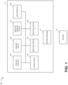
- FIG. 1 illustrates a negative pressure therapy system 100 that includes a TNP apparatus 11 and a wound 14 according to some embodiments.
- the TNP apparatus 11 can be used to treat the wound 14.
- the TNP apparatus 11 can include control circuitry 12A, memory 12B, a negative pressure source 12C, a user interface 12D, a power source 12E, a first pressure sensor 12F, and a second pressure sensor 12G that are configured to electrically communicate with one another.
- the TNP apparatus 11 can include a wound dressing 13.
- the power source 12E can provide power to one or more components of the TNP apparatus 11.
- control circuitry 12A, memory device 12B, negative pressure source 12C, user interface 12D, power source 12E, first pressure sensor 12F, and second pressure sensor 12G can be integral with, incorporated as part of, attached to, or disposed in the wound dressing 13.
- the TNP apparatus 11 can accordingly be considered to have its control electronics and pump on-board the wound dressing 13 rather than separate from the wound dressing 13.
- the control circuitry 12A can include one or more controllers (for example, a microcontroller or microprocessor), activation circuits, boost converters, current limiters, feedback conditioning circuits, and H-bridge inverters.
- the control circuitry 12A can control the operations of one or more other components of the TNP apparatus 11 according at least to instructions stored in the memory device 12B.
- the control circuitry 12A can, for instance, control operations of and supply of negative pressure by the negative pressure source 12C.
- the negative pressure source 12C can include a pump, such as, without limitation, a rotary diaphragm pump or other diaphragm pump, a piezoelectric pump, a peristaltic pump, a piston pump, a rotary vane pump, a liquid ring pump, a scroll pump, a pump operated by a piezoelectric transducer, or any other suitable pump or micropump or any combinations of the foregoing.
- the pump can include an actuator driven by a source of energy, such as electrical energy, mechanical energy, and the like.
- the actuator can be an electric motor, a piezoelectric transducer, a voice coil actuator, an electroactive polymer, a shape-memory alloy, a comb drive, a hydraulic motor, a pneumatic actuator, a screw jack, a servomechanism, a solenoid actuator, a stepper motor, a plunger, a combustion engine, and the like.
- the negative pressure source 12C can supply negative pressure by converting electrical energy to mechanical energy without converting the electrical energy to magnetic energy.
- the negative pressure source 12C can have a different impact when electrically coupled to one or more other components of the control circuitry 12A than if the negative pressure source 12C supplied negative pressure by converting the electrical energy to the magnetic energy and then to the mechanical energy.
- the user interface 12D can include one or more elements that receive user inputs or provide user outputs to a patient or caregiver.
- the one or more elements that receive user inputs can include buttons, switches, dials, touch screens, or the like, and the one or more elements that provide user outputs can include activation of a light emitting diode (LED) or one or more pixels of the display or activation of a speaker or the like.
- the user interface 12D can include a switch to receive user inputs (for instance, a negative pressure activation or deactivation input) and two LEDs to indicate an operating status (for example, functioning normally, under fault condition, or awaiting user input) of the TNP apparatus 11.
- the first pressure sensor 12F can be used to monitor pressure underneath the wound dressing 13, such as pressure in a fluid flow path connecting the negative pressure source 12C and the wound 14, pressure at the wound 14, or pressure in the negative pressure source 12C.
- the second pressure sensor 12G can be used to monitor pressure external to the wound dressing 13.
- the pressure external to the wound dressing can be atmospheric pressure; however, the atmospheric pressure can vary depending on, for instance, an altitude of use or pressurized environment in which the TNP apparatus 11 may be used.
- the control circuitry 12A can control the supply of negative pressure by the negative pressure source 12C according at least to a comparison between the pressure monitored by the first pressure sensor 12F and the pressure monitored by the second pressure sensor 12G.
- the wound dressing 13 can include a wound contact layer, a spacer layer, and an absorbent layer.
- the wound contact layer can be in contact with the wound 14.
- the wound contact layer can include an adhesive on the patient facing side for securing the dressing to the skin surrounding the wound 14 or on the top side for securing the wound contact layer to a cover layer or other layer of the wound dressing 13.
- the wound contact layer can provide unidirectional flow so as to facilitate removal of exudate from the wound while blocking or substantially preventing exudate from returning to the wound 14.
- the spacer layer can assist in distributing negative pressure over the wound site and facilitating transport of wound exudate and fluids into the wound dressing 13.
- the absorbent layer can absorb and retain exudate aspirated from the wound 14.
- the control circuitry 12A can monitor the activity of the negative pressure source 12C, which may include monitoring a duty cycle of the negative pressure source 12C (for example, the duty cycle of the actuator of the negative pressure source).
- a duty cycle of the negative pressure source 12C for example, the duty cycle of the actuator of the negative pressure source.
- the "duty cycle” can reflect the amount of time the negative pressure source 12C is active or running over a period of time. In other words, the duty cycle can reflect time that the negative pressure source 12C is in an active state as a fraction of total time under consideration.
- Duty cycle measurements can reflect a level of activity of the negative pressure source 12C. For example, the duty cycle can indicate that the negative pressure source 12C is operating normally, working hard, working extremely hard, etc.
- the duty cycle measurements can reflect various operating conditions, such as presence or severity of leaks, rate of flow of fluid (for instance, air, liquid, or solid exudate, etc.) aspirated from a wound, or the like.
- the controller can execute or be programmed to execute algorithms or logic that control the operation of the system.
- duty cycle measurements can indicate presence of a high leak, and the control circuitry 12A can be programmed to indicate this condition to a user (for instance, patient, caregiver, or physician) or temporarily suspend or pause operation of the source of negative pressure in order to conserve power.
- the wound dressing 13 can create a substantially sealed or closed space around the wound 13 and under the wound dressing 13, and the first pressure sensor 12F can periodically or continuously measure or monitor a level of pressure in this space.
- the control circuitry 12A can control the level of pressure in the space between a first negative pressure set point limit and at least a second negative pressure set point limit.
- the first set point limit can be approximately -70 mmHg, or from approximately -60 mmHg or less to approximately -80 mmHg or more.
- the second set point limit can be approximately -90 mmHg, or from approximately -80 mmHg or less to approximately -100 mmHg or more.
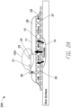
- FIG. 2A illustrates a side view of a negative pressure therapy system 200
- FIG. 2B illustrates a top view of the negative pressure therapy system 200 according to some embodiments.
- the negative pressure therapy system 200 can be an example implementation of the negative pressure therapy system 100.
- the wound dressing 13 of the TNP apparatus 11 is shown as attached to the wound 14. Arrows depict the flow of air through the wound dressing 13 and wound exudate from the wound 14.
- the TNP apparatus 11 can include an air exhaust 26 and a component area 25, such as a components housing or storage area for components of the TNP apparatus 11 like one or more of the control circuitry 12A, memory device 12B, negative pressure source 12C, user interface 12D, power source 12E, first pressure sensor 12F, and second pressure sensor 12G.
- the user interface 12D of the negative pressure therapy system 200 can include a switch 21 (such as a dome switch), a first indicator 23 (such as a first LED), and a second indicator 24 (such as a second LED).
- the switch 21 can receive a negative pressure activation or deactivation user input (for example, such as receiving the activation or deactivation user input in response to depression of the switch 21 for a period of time, like from between 0.5 seconds and 5 seconds).
- the first indicator 23 and the second indicator 24 can indicate an operating status like functioning normally, under fault condition, or awaiting user input.
- the switch 21 can couple to a power supply connection of the negative pressure source 12C or the control circuitry 12A or an enable signal of the negative pressure source 12C or the control circuitry 12A to activate or deactivate supply of negative pressure or disable supply of negative pressure.
- Component parts of the wound dressing 13 of the negative pressure therapy system 200 are illustrated to include an airlock layer 27, an absorbing layer 28, and a contact layer 29.
- the airlock layer 27 can enable air flow.
- the absorbing layer 28 can absorb wound exudate.
- the contact layer 29 can be soft and include silicon and be used to couple the TNP apparatus 11 to the patient.
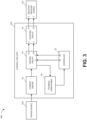
- FIG. 3 illustrates a block diagram 300 depicting example electrical communication paths between the power source 12D, control circuitry 12A, and negative pressure source 12C, as well as example components of the control circuitry 12A including a controller 31, a current limiter 32, a driving circuit 33, a feedback conditioner 34, and the coupling circuit 35.
- FIG. 3 shows, in particular, how the controller 31 can be used to control the supply of negative pressure by the negative pressure source 12C according to some embodiments.
- the power source 12D can include one or more power supplies, such as batteries (such as, multiple 3 V batteries) or a connection to mains power, to provide power for one or more components of the TNP apparatus 11.
- the power source 12D can, for instance, provide electrical current and voltage to the current limiter 32.
- the voltage output by the power source 12D can be around 30 V, such as 29 V ⁇ 1 V, in some implementations.
- the power source 12D can additionally include circuitry, such as a boost converter, to control the electrical current and voltage provided to the current limiter 32.
- the current limiter 32 can serve to limit or clamp the current at a maximum current level, such as at 100 mA, 250 mA, 466 mA, 500 mA, or 1 A, to limit potential fault current through the driving circuit 33 and the negative pressure source 12C. Under normal operation (for example, in most or some instances), the current limiter 32 may not operate to limit current or voltage.
- the current limiter 32 can provide electric current and voltage to the driving circuit 33.
- the driving circuit 33 can include an H-bridge circuit composed of multiple switches.
- the H-bridge can be constructed to operate as an H-bridge inverter.
- the driving circuit 33 can provide feedback to the controller 31 via the feedback conditioner 34.
- the feedback conditioner 34 can be used, for instance, to condition current feedback information from the driving circuit 33 before the current feedback information is provided to the controller 31.
- the feedback conditioner 34 can include a low-pass filter (which can, for example, include active circuit components) to filter switching noise caused by the switching of one or more switches of the driving circuit 33.
- the controller 31 can, in turn, control the operations of the driving circuit 33 based on the feedback, in some instances.
- the controller 31 can control operations of the driving circuit 33, and in turn the negative pressure source 12C, by outputting one or more control signals via one or more outputs of the controller 31 to one or more inputs of the driving circuit 33.
- the controller 31 can output a first control signal via a first output O1 of the controller 31 to a first input I1 of the driving circuit 33 and a second control signal via a second output O2 of the controller 31 to a second input I2 of the driving circuit 33.
- the controller 31 can vary a pulse width modulation (PWM) of the first and second control signals to adjust an electrical current and voltage provided by the driving circuit 33 to the coupling circuit 35 and then to the negative pressure source 12C.
- PWM pulse width modulation
- the electrical current or voltage provided by the driving circuit 33 may, in some instances, be referred to herein as a driving signal.
- the driving circuit 33 can include an H-bridge, and the controller 31 can generate the first and second control signals to cause the H-bridge to output the driving signal having a square waveform (such as ⁇ 3 V, ⁇ 5 V, ⁇ 10 V, ⁇ 15 V, ⁇ 20 V, ⁇ 25 V, ⁇ 30 V, or ⁇ 40 V) with a frequency (such as 10 kHz to 32 kHz, 14 kHz to 28kHz, 18 kHz to 24 kHz, 20 KHz to 22 KHz, or about 21 kHz) and a duty cycle or ratio (such as 20%, 30%, 40%, 45%, 50%, 55%, 60%, 70%, or 80%) via a first output O1 of the driving circuit 33 and a second output O2 of the driving circuit 33.
- a square waveform such as ⁇ 3 V, ⁇ 5 V, ⁇ 10 V, ⁇ 15 V, ⁇ 20 V, ⁇ 25 V, ⁇ 30 V, or ⁇ 40 V
- a frequency such as 10 kHz to 32
- the driving circuit 33 can control supply negative pressure by the negative pressure source 12C by providing the driving signal to the negative pressure source 12C (for example, to the actuator of the negative pressure source 12C) via the coupling circuit 35.
- the driving circuit 33 can, for instance, output electrical currents via the first and second outputs O1 and O2 of the driving circuit 33 to a first input I1 of the coupling circuit 35 and a second input I2 of the coupling circuit 35.
- the coupling circuit 35 can, in turn, output electrical currents via a first output O1 of the coupling circuit 35 and a second output O2 of the coupling circuit 35 to a first input I1 of the negative pressure source 12C and a second input I2 of the negative pressure source 12C.
- the electrical currents output by the driving circuit 33 and the coupling circuit 35 can notably be considered to result in positive charge flowing away from the driving circuit 33 (that is, sourcing of electrical current by the driving circuit 33) or toward the driving circuit 33 (that is, sinking of electrical current by the driving circuit 33).
- the coupling circuit 35 can serve to limit a rate of change over time of the current supplied by the driving circuit 33 to the negative pressure source 12C or limit a rate of change over time of a voltage across first and second inputs I1 and I2 of the negative pressure source 12C.
- the coupling circuit 35 can have an inductive reactance greater than 1 m ⁇ , 5 m ⁇ , 10 m ⁇ , 50 m ⁇ , 100 m ⁇ , 500 m ⁇ , 750 m ⁇ at an operating frequency of 1 kHz.
- the coupling circuit 35 can include passive circuit elements and not include active circuit elements, but in other embodiments, the coupling circuit 35 can include one or both of passive circuit elements and active circuit elements.
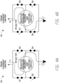
- FIGS. 4A and 4B illustrate example simplified circuit components of the driving circuit 33 according to some embodiments.
- the driving circuit 33 can be composed of at least four switches, including a first switch S1, a second switch S2, a third switch S3, and a fourth switch S4 but together form an H-bridge.
- the first and fourth switches S1 and S4 can be closed at the same time and the second and third switches S2 and S3 can be opened at the same time, as shown in FIG. 4A , to supply a first current i1 in a first direction through the coupling circuit 35 and the negative pressure source 12C.
- the second and third switches S2 and S3 can be closed at the same time and the first and fourth switches S1 and S4 can be opened at the same time, as shown in FIG. 4B , to supply a second current i2 in a second direction through the coupling circuit 35 and the negative pressure source 12C.
- the first direction can be opposite the second direction.
- FIG. 4C illustrates example circuit components of the driving circuit 33 (an H-bridge in the illustrated example) that include a resistor 42 according to some embodiments.
- the electrical current that travels through the resistor 42 can be the same or substantially the same as the electrical current that travels through the coupling circuit 35 and the negative pressure source 12C (for example, the actuator of the negative pressure source 12C).
- a feedback provided to the feedback conditioner 34 can, for instance, be a voltage level or drop across the resistor 42, which can be proportional to the electrical current that travels through the resistor 42, as well as the electrical current that travels through the coupling circuit 35 and the negative pressure source 12C.
- the resistor 42 thus can be used to measure one or more properties of the electrical current, such as a magnitude, that is fed to the negative pressure source 12C via the coupling circuit 35, such as via an inductor of the coupling circuit 35 like an inductor 52 described with respect to FIG. 5 .
- the resistor 42 can be coupled to a low-pass filter, as described herein.
- FIG. 5 illustrates example circuit components of the coupling circuit 35 according to some embodiments.
- the coupling circuit 35 can include (i) the inductor 52 electrically coupled in series between the first output O1 of the driving circuit 33 and the first input I1 of the negative pressure source 12C and (ii) a wire or an electrical short 54 electrically coupled in series between the second output O2 of the driving circuit 23 and the second input I2 of the negative pressure source 12C.
- the inductor can have an inductance ranging from 0.1 ⁇ H to 1000 ⁇ H, 1 ⁇ H to 100 ⁇ H, or 3 ⁇ H to 10 ⁇ H, or an inductance of about 7.5 ⁇ H.
- the inductor can have a maximum current rating of greater than 0.25 A, 0.5 A, 0.75 A, 1 A, or 1.25 A.
- the inductor 52 can be used to oppose rapid changes in a current or voltage supplied to drive the negative pressure source 12C.
- the coupling circuit 35 can include (i) a first wire or a first electrical short electrically coupled in series between the first output O1 of the driving circuit 33 and the first input I1 of the negative pressure source 12C and (ii) a second wire or a second electrical short electrically coupled in series between the second output O2 of the driving circuit 33 and the second input I2 of the negative pressure source 12C.
- the coupling circuit 35 can include (i) a first wire or a first electrical short electrically coupled in series between the first output O1 of the driving circuit 33 and the first input I1 of the negative pressure source 12C and (ii) an inductor (such as the inductor 52) electrically coupled in series between the second output O2 of the driving circuit 33 and the second input I2 of the negative pressure source 12C.
- the coupling circuit 35 can include (i) a first inductor (such as the inductor 52) electrically coupled in series between the first output O1 of the driving circuit 33 and the first input I1 of the negative pressure source 12C and (ii) a second inductor (such as the inductor 52) electrically coupled in series between the second output O2 of the driving circuit 33 and the second input I2 of the negative pressure source 12C.
- a first inductor such as the inductor 52
- a second inductor such as the inductor 52
- one or more active elements can be used in place of or in addition to one or more inductors.
- FIG. 6 illustrates a therapy control process 600 performable by an apparatus, such as the TNP apparatus 11 according to some embodiments.
- the therapy control process 600 is described in the context of the TNP apparatus 11, but may instead be implemented in other systems described herein, or by other systems not shown.
- the therapy control process 600 can generate and output a control signal.
- the controller 31 can generate and output a control signal to the driving circuit 33.
- the therapy control process 600 can activate switches responsive to the control signal.
- the driving circuit 33 can selectively open and close one or more switches of the driving circuit 33 responsive to the control signal.
- the therapy control process 600 can supply a driving signal via the switches.
- the driving circuit 33 can supply the driving signal to the coupling circuit 35 via opening and closing of the one or more switches of the driving circuit 33.
- the therapy control process 600 can limit a rate of change over time of the driving signal.
- the coupling circuit 35 can limit a rate of change over time of the driving signal from the driving circuit 33 using an inductive reactance.
- the therapy control process 600 can supply negative pressure responsive to the driving signal.
- the negative pressure source 33 can supply negative pressure to the wound dressing 13 responsive to the driving signal provided by the driving circuit 33 via the coupling circuit 35.
- any value of a threshold, limit, duration, etc. provided herein is not intended to be absolute and, thereby, can be approximate.
- any threshold, limit, duration, etc. provided herein can be fixed or varied either automatically or by a user.
- relative terminology such as exceeds, greater than, less than, etc. in relation to a reference value is intended to also encompass being equal to the reference value. For example, exceeding a reference value that is positive can encompass being equal to or greater than the reference value.
- relative terminology such as exceeds, greater than, less than, etc. in relation to a reference value is intended to also encompass an inverse of the disclosed relationship, such as below, less than, greater than, etc. in relations to the reference value.
- blocks of the various processes may be described in terms of determining whether a value meets or does not meet a particular threshold, the blocks can be similarly understood, for example, in terms of a value (i) being below or above a threshold or (ii) satisfying or not satisfying a threshold.
- the various components illustrated in the figures may be implemented as software or firmware on a processor, controller, ASIC, FPGA, or dedicated hardware.
- Hardware components such as processors, ASICs, FPGAs, and the like, can include logic circuitry.
- User interface screens illustrated and described herein can include additional or alternative components. These components can include menus, lists, buttons, text boxes, labels, radio buttons, scroll bars, sliders, checkboxes, combo boxes, status bars, dialog boxes, windows, and the like. User interface screens can include additional or alternative information. Components can be arranged, grouped, displayed in any suitable order.
- the term "or” is used in its inclusive sense (and not in its exclusive sense) so that when used, for example, to connect a list of elements, the term “or” means one, some, or all of the elements in the list.
- the term “each,” as used herein, in addition to having its ordinary meaning, can mean any subset of a set of elements to which the term “each” is applied.
- the terms “generally parallel” and “substantially parallel” refer to a value, amount, or characteristic that departs from exactly parallel by less than or equal to 15 degrees, 10 degrees, 5 degrees, 3 degrees, 1 degree, or 0.1 degree.
Landscapes
- Health & Medical Sciences (AREA)
- Heart & Thoracic Surgery (AREA)
- Vascular Medicine (AREA)
- Engineering & Computer Science (AREA)
- Anesthesiology (AREA)
- Biomedical Technology (AREA)
- Hematology (AREA)
- Life Sciences & Earth Sciences (AREA)
- Animal Behavior & Ethology (AREA)
- General Health & Medical Sciences (AREA)
- Public Health (AREA)
- Veterinary Medicine (AREA)
- External Artificial Organs (AREA)
- Accommodation For Nursing Or Treatment Tables (AREA)
Claims (11)
- Eine Vorrichtung zum Anlegen von Unterdruck an eine Wunde, wobei die Vorrichtung Folgendes beinhaltet:eine Unterdruckquelle (12C), die konfiguriert ist, um über einen Fluidströmungspfad einem Wundverband (13), der über einer Wunde eines Patienten platziert ist,Unterdruck bereitzustellen, wobei die Unterdruckquelle eine Betätigungseinrichtung beinhaltet, die konfiguriert ist, um eine elektrische Energie in eine mechanische Energie umzuwandeln;eine Kopplungsschaltung;eine Treiberschaltung, die konfiguriert ist, um der Betätigungseinrichtung über die Kopplungsschaltung ein Treibsignal zuzuführen, um die Unterdruckquelle zu veranlassen, Unterdruck bereitzustellen;eine Steuereinrichtung, die konfiguriert ist, um das Treibsignal zu steuern, das von der Treiberschaltung zugeführt wird, und dadurch gekennzeichnet, dassdie Kopplungsschaltung ein induktives Bauelement mit einem induktiven Blindwiderstand beinhaltet, wobei das induktive Bauelement elektrisch in Reihe zwischen einen Ausgang der Treiberschaltung und einen Eingang der Betätigungseinrichtung gekoppelt ist, und wobei die Kopplungsschaltung einen elektrischen Kurzschluss beinhaltet, der elektrisch in Reihe zwischen einen anderen Ausgang der Treiberschaltung und einen anderen Eingang der Betätigungseinrichtung gekoppelt ist.
- Vorrichtung gemäß Anspruch 1, wobei die Betätigungseinrichtung konfiguriert ist, um Unterdruck durch Umwandlung der elektrischen Energie in die mechanische Energie zu erzeugen, ohne die elektrische Energie in eine magnetische Energie umzuwandeln.
- Vorrichtung gemäß Anspruch 1, wobei die Unterdruckquelle eine piezoelektrische Pumpe beinhaltet und die Betätigungseinrichtung einen piezoelektrischen Wandler beinhaltet.
- Vorrichtung gemäß Anspruch 1, wobei die Unterdruckquelle eine Mikropumpe beinhaltet.
- Vorrichtung gemäß Anspruch 1, die ferner den Wundverband beinhaltet, wobei die Unterdruckquelle auf dem oder innerhalb des Wundverbands angeordnet ist.
- Vorrichtung gemäß Anspruch 1, wobei der induktive Blindwiderstand größer als 5 mΩ bei einer Betriebsfrequenz von 1 kHz ist.
- Vorrichtung gemäß Anspruch 1, wobei das induktive Bauelement eine Induktivität zwischen 1 µH und 100 µH aufweist.
- Vorrichtung gemäß Anspruch 7, wobei das induktive Bauelement eine maximale Strombelastbarkeit von mindestens 1 A aufweist.
- Vorrichtung gemäß Anspruch 1, wobei die Treiberschaltung eine H-Brückenschaltung beinhaltet.
- Vorrichtung gemäß Anspruch 1, wobei die Steuereinrichtung ferner konfiguriert ist, um der Treiberschaltung ein Steuersignal bereitzustellen, und die Steuereinrichtung konfiguriert ist, um das Treibsignal durch Einstellen einer Pulsbreitenmodulation des Steuersignals zu steuern.
- Vorrichtung gemäß Anspruch 1, wobei eine Größe des Treibsignals weniger als 50 V beträgt.
Applications Claiming Priority (3)
| Application Number | Priority Date | Filing Date | Title |
|---|---|---|---|
| US201662331109P | 2016-05-03 | 2016-05-03 | |
| US201762479592P | 2017-03-31 | 2017-03-31 | |
| PCT/EP2017/060470 WO2017191158A1 (en) | 2016-05-03 | 2017-05-03 | Systems and methods for driving negative pressure sources in negative pressure therapy systems |
Publications (2)
| Publication Number | Publication Date |
|---|---|
| EP3452131A1 EP3452131A1 (de) | 2019-03-13 |
| EP3452131B1 true EP3452131B1 (de) | 2025-01-01 |
Family
ID=58669792
Family Applications (1)
| Application Number | Title | Priority Date | Filing Date |
|---|---|---|---|
| EP17721366.7A Active EP3452131B1 (de) | 2016-05-03 | 2017-05-03 | Systeme und verfahren zum betrieb von unterdruckquellen in unterdrucktherapiesystemen |
Country Status (7)
| Country | Link |
|---|---|
| US (1) | US11305047B2 (de) |
| EP (1) | EP3452131B1 (de) |
| JP (1) | JP6975172B2 (de) |
| CN (1) | CN109069711A (de) |
| AU (1) | AU2017259003B2 (de) |
| CA (1) | CA3022587A1 (de) |
| WO (1) | WO2017191158A1 (de) |
Families Citing this family (22)
| Publication number | Priority date | Publication date | Assignee | Title |
|---|---|---|---|---|
| JP6911043B2 (ja) | 2016-03-07 | 2021-07-28 | スミス アンド ネフュー ピーエルシーSmith & Nephew Public Limited Company | 陰圧源が創傷被覆材内に一体化された創傷治療装置及び方法 |
| CN114469523A (zh) | 2016-04-26 | 2022-05-13 | 史密夫及内修公开有限公司 | 与具有流体侵入抑制部件的一体化负压源一起使用的伤口敷料和方法 |
| EP3452131B1 (de) | 2016-05-03 | 2025-01-01 | Smith & Nephew plc | Systeme und verfahren zum betrieb von unterdruckquellen in unterdrucktherapiesystemen |
| CA3038206A1 (en) | 2016-05-03 | 2017-11-09 | Smith & Nephew Plc | Optimizing power transfer to negative pressure sources in negative pressure therapy systems |
| WO2017191154A1 (en) | 2016-05-03 | 2017-11-09 | Smith & Nephew Plc | Negative pressure wound therapy device activation and control |
| AU2017315129B2 (en) | 2016-08-25 | 2022-10-27 | Smith & Nephew Plc | Absorbent negative pressure wound therapy dressing |
| US11564847B2 (en) | 2016-09-30 | 2023-01-31 | Smith & Nephew Plc | Negative pressure wound treatment apparatuses and methods with integrated electronics |
| US12447260B2 (en) | 2016-09-30 | 2025-10-21 | Smith & Nephew Plc | Negative pressure wound treatment apparatuses and methods with integrated electronics |
| US12005181B2 (en) | 2016-12-12 | 2024-06-11 | Smith & Nephew Plc | Pressure wound therapy status indication via external device |
| EP3592312B1 (de) | 2017-03-08 | 2024-01-10 | Smith & Nephew plc | Unterdruckwundtherapievorrichtungsteuerung in gegenwart eines fehlerzustands |
| JP7121050B2 (ja) | 2017-05-09 | 2022-08-17 | スミス アンド ネフュー ピーエルシー | 陰圧創傷療法システムの冗長制御 |
| GB201718070D0 (en) | 2017-11-01 | 2017-12-13 | Smith & Nephew | Negative pressure wound treatment apparatuses and methods with integrated electronics |
| AU2018331954B2 (en) | 2017-09-13 | 2024-07-04 | Smith & Nephew Plc | Negative pressure wound treatment apparatuses and methods with integrated electronics |
| GB201718072D0 (en) | 2017-11-01 | 2017-12-13 | Smith & Nephew | Negative pressure wound treatment apparatuses and methods with integrated electronics |
| GB201718054D0 (en) | 2017-11-01 | 2017-12-13 | Smith & Nephew | Sterilization of integrated negative pressure wound treatment apparatuses and sterilization methods |
| US11497653B2 (en) | 2017-11-01 | 2022-11-15 | Smith & Nephew Plc | Negative pressure wound treatment apparatuses and methods with integrated electronics |
| WO2019157466A1 (en) | 2018-02-12 | 2019-08-15 | Healyx Labs, Inc. | Negative pressure wound therapy systems, devices, and methods |
| USD898925S1 (en) | 2018-09-13 | 2020-10-13 | Smith & Nephew Plc | Medical dressing |
| GB201903774D0 (en) | 2019-03-20 | 2019-05-01 | Smith & Nephew | Negative pressure wound treatment apparatuses and methods with integrated electronics |
| EP4226963A1 (de) * | 2019-04-17 | 2023-08-16 | ResMed Pty Ltd | Cpap-system mit einem wasserreservoir |
| GB201907716D0 (en) | 2019-05-31 | 2019-07-17 | Smith & Nephew | Systems and methods for extending operational time of negative pressure wound treatment apparatuses |
| CN114469519B (zh) * | 2022-01-27 | 2022-08-05 | 长沙海润生物技术有限公司 | 一种负压耦合电场信号反馈治疗系统 |
Family Cites Families (344)
| Publication number | Priority date | Publication date | Assignee | Title |
|---|---|---|---|---|
| US3874387A (en) | 1972-07-05 | 1975-04-01 | Pasquale P Barbieri | Valved hemostatic pressure cap |
| US4224941A (en) | 1978-11-15 | 1980-09-30 | Stivala Oscar G | Hyperbaric treatment apparatus |
| US4398910A (en) | 1981-02-26 | 1983-08-16 | Blake L W | Wound drain catheter |
| US4534356A (en) | 1982-07-30 | 1985-08-13 | Diamond Shamrock Chemicals Company | Solid state transcutaneous blood gas sensors |
| US4569674A (en) | 1982-08-03 | 1986-02-11 | Stryker Corporation | Continuous vacuum wound drainage system |
| DE3323973A1 (de) | 1983-07-02 | 1985-01-03 | Boehringer Mannheim Gmbh, 6800 Mannheim | Erythrozyten-rueckhaltesubstrate |
| US4624656A (en) | 1983-07-25 | 1986-11-25 | Hospitak, Inc. | Hyperbaric gas treatment device |
| DE3441891A1 (de) | 1984-11-16 | 1986-05-28 | Walter Beck | Verfahren und vorrichtung zum absaugen von sekretfluessigkeit aus einer wunde |
| DE3601363A1 (de) | 1986-01-18 | 1988-12-29 | Stierlen Maquet Ag | Elektrisches schaltelement |
| US5527293A (en) | 1989-04-03 | 1996-06-18 | Kinetic Concepts, Inc. | Fastening system and method |
| US5056510A (en) | 1989-04-13 | 1991-10-15 | The Kendall Company | Vented wound dressing |
| US4979944A (en) | 1989-08-21 | 1990-12-25 | The Pullman Company | Surgical vacuum evacuation device |
| US5181905A (en) | 1989-11-28 | 1993-01-26 | Eric Flam | Method of monitoring the condition of the skin or wound |
| US5152757A (en) | 1989-12-14 | 1992-10-06 | Brigham And Women's Hospital | System for diagnosis and treatment of wounds |
| US5055198A (en) | 1990-03-07 | 1991-10-08 | Shettigar U Ramakrishna | Autologous blood recovery membrane system and method |
| JPH04354722A (ja) | 1991-05-30 | 1992-12-09 | Nippondenso Co Ltd | 電子荷札 |
| AU662901B2 (en) | 1991-05-07 | 1995-09-21 | Nippondenso Co. Ltd. | Electronic tag |
| US5636643A (en) | 1991-11-14 | 1997-06-10 | Wake Forest University | Wound treatment employing reduced pressure |
| US5266928A (en) | 1992-05-29 | 1993-11-30 | Johnson Lonnie G | Wet diaper detector |
| US5964723A (en) | 1992-06-19 | 1999-10-12 | Augustine Medical, Inc. | Normothermic tissue heating wound covering |
| USD357743S (en) | 1992-12-31 | 1995-04-25 | Alza Corporation | Electrotransport drug delivery system |
| US5902256A (en) | 1993-02-12 | 1999-05-11 | Jb Research, Inc. | Massage unit with replaceable hot and cold packs |
| GB9400994D0 (en) | 1994-01-20 | 1994-03-16 | Bristol Myers Squibb Co | Wound dressing |
| US5549584A (en) | 1994-02-14 | 1996-08-27 | The Kendall Company | Apparatus for removing fluid from a wound |
| EP0777504B1 (de) | 1994-08-22 | 1998-10-21 | Kinetic Concepts, Inc. | Wunddrainagevorrichtung |
| JPH0870590A (ja) | 1994-08-30 | 1996-03-12 | Olympus Optical Co Ltd | 超音波振動子の駆動装置 |
| US5643189A (en) | 1994-12-07 | 1997-07-01 | Masini; Michael A. | Composite wound dressing including inversion means |
| US6599262B1 (en) | 1994-12-07 | 2003-07-29 | Masini Michael A | Bandage with thermal insert |
| US6225523B1 (en) | 1994-12-07 | 2001-05-01 | Masini Michael A | Invertible wound dressings and method of making the same |
| US6261276B1 (en) | 1995-03-13 | 2001-07-17 | I.S.I. International, Inc. | Apparatus for draining surgical wounds |
| US5779657A (en) | 1995-07-21 | 1998-07-14 | Daneshvar; Yousef | Nonstretchable wound cover and protector |
| GB9523253D0 (en) | 1995-11-14 | 1996-01-17 | Mediscus Prod Ltd | Portable wound treatment apparatus |
| US6783328B2 (en) | 1996-09-30 | 2004-08-31 | Terumo Cardiovascular Systems Corporation | Method and apparatus for controlling fluid pumps |
| DE19722075C1 (de) | 1997-05-27 | 1998-10-01 | Wilhelm Dr Med Fleischmann | Vorrichtung zur Applikation von Wirkstoffen an einer Wundoberfläche |
| US6071267A (en) | 1998-02-06 | 2000-06-06 | Kinetic Concepts, Inc. | Medical patient fluid management interface system and method |
| US6458109B1 (en) | 1998-08-07 | 2002-10-01 | Hill-Rom Services, Inc. | Wound treatment apparatus |
| US6168800B1 (en) | 1998-08-20 | 2001-01-02 | Medwrap Corporation | Antimcrobial multi-layer island dressing |
| DE19844355A1 (de) | 1998-09-28 | 2000-04-06 | Rainer E Sachse | Wundverband mit integrierter Saugvorrichtung |
| GB9822341D0 (en) | 1998-10-13 | 1998-12-09 | Kci Medical Ltd | Negative pressure therapy using wall suction |
| WO2000078212A1 (en) | 1999-06-18 | 2000-12-28 | University Of Virginia Patent Foundation | An apparatus for fluid transport and related method thereof |
| US6261283B1 (en) | 1999-08-31 | 2001-07-17 | Alcon Universal Ltd. | Liquid venting surgical system and cassette |
| CA2390131C (en) | 1999-11-29 | 2009-06-23 | Hill-Rom Services, Inc. | Wound treatment apparatus |
| US6183438B1 (en) | 2000-01-04 | 2001-02-06 | Ramon Berguer | Catheter with centering wire |
| US20050119737A1 (en) | 2000-01-12 | 2005-06-02 | Bene Eric A. | Ocular implant and methods for making and using same |
| DE20000887U1 (de) | 2000-01-19 | 2001-06-07 | Riesinger, geb. Dahlmann, Birgit, 48346 Ostbevern | Auffangbeutel mit Aufsaugvorrichtung |
| US6794554B2 (en) | 2000-02-01 | 2004-09-21 | Ferris Pharmaceuticals, Inc. | Wound packing material |
| JP2004509658A (ja) | 2000-05-22 | 2004-04-02 | コフィー,アーサー,シー. | 小腸粘膜下組織と真空包帯の組合せとその使用方法 |
| US6685681B2 (en) | 2000-11-29 | 2004-02-03 | Hill-Rom Services, Inc. | Vacuum therapy and cleansing dressing for wounds |
| US6855135B2 (en) | 2000-11-29 | 2005-02-15 | Hill-Rom Services, Inc. | Vacuum therapy and cleansing dressing for wounds |
| US6976977B2 (en) | 2000-12-06 | 2005-12-20 | Sherwood Services Ag | Vacuum setting and indication system for a drainage device |
| JP4408018B2 (ja) | 2001-01-18 | 2010-02-03 | ナワ−ハイルミッテル ゲーエムベーハー | 包帯材および該包帯材とともに使用される処置溶液 |
| US7070584B2 (en) | 2001-02-20 | 2006-07-04 | Kci Licensing, Inc. | Biocompatible wound dressing |
| US7700819B2 (en) | 2001-02-16 | 2010-04-20 | Kci Licensing, Inc. | Biocompatible wound dressing |
| US7108683B2 (en) | 2001-04-30 | 2006-09-19 | Kci Licensing, Inc | Wound therapy and tissue management system and method with fluid differentiation |
| ES2345038T3 (es) * | 2001-07-12 | 2010-09-14 | Kci Medical Resources | Control de la velocidad de cambio de vacio. |
| US7004915B2 (en) | 2001-08-24 | 2006-02-28 | Kci Licensing, Inc. | Negative pressure assisted tissue treatment system |
| US6787682B2 (en) | 2001-11-05 | 2004-09-07 | Hollister Incorporated | Absorbent foam wound dressing |
| US7645253B2 (en) | 2001-11-16 | 2010-01-12 | National Quality Care, Inc. | Wearable ultrafiltration device |
| US6648862B2 (en) | 2001-11-20 | 2003-11-18 | Spheric Products, Ltd. | Personally portable vacuum desiccator |
| GB2382305B (en) | 2001-11-23 | 2004-12-15 | Johnson & Johnson Medical Ltd | Absorbent wound dressings containing a hydrogel layer |
| EP1627662B1 (de) | 2004-06-10 | 2011-03-02 | Candela Corporation | Apparat für vakuumunterstützte dermatologische Phototherapien |
| WO2003057070A2 (en) | 2001-12-26 | 2003-07-17 | Hill-Rom Services Inc. | Vented vacuum bandage and method |
| ATE387919T1 (de) | 2001-12-26 | 2008-03-15 | Hill Rom Services Inc | Vakuumbindenverpackung |
| US7338482B2 (en) | 2002-02-28 | 2008-03-04 | Hill-Rom Services, Inc. | External catheter access to vacuum bandage |
| US6942633B2 (en) | 2002-03-22 | 2005-09-13 | Twin Star Medical, Inc. | System for treating tissue swelling |
| AU2002359824A1 (en) | 2002-04-10 | 2003-10-27 | Hill-Rom Services, Inc. | Access openings in vacuum bandage |
| DE20207356U1 (de) | 2002-05-08 | 2003-06-12 | Riesinger, Birgit, 48346 Ostbevern | Absorptionskörper zum Anschluß an Haut- und Schleimhautoberflächen |
| US20030212357A1 (en) | 2002-05-10 | 2003-11-13 | Pace Edgar Alan | Method and apparatus for treating wounds with oxygen and reduced pressure |
| ES2642724T3 (es) | 2002-05-31 | 2017-11-17 | Kci Medical Resources | Aparato de tratamiento de heridas |
| EP2545946B1 (de) | 2002-08-21 | 2016-11-16 | KCI Medical Resources | Wundpackung zur vorbeugung des wundverschlusses |
| US7846141B2 (en) | 2002-09-03 | 2010-12-07 | Bluesky Medical Group Incorporated | Reduced pressure treatment system |
| US6979324B2 (en) | 2002-09-13 | 2005-12-27 | Neogen Technologies, Inc. | Closed wound drainage system |
| US7520872B2 (en) | 2002-09-13 | 2009-04-21 | Neogen Technologies, Inc. | Closed wound drainage system |
| US7815616B2 (en) | 2002-09-16 | 2010-10-19 | Boehringer Technologies, L.P. | Device for treating a wound |
| GB0224986D0 (en) | 2002-10-28 | 2002-12-04 | Smith & Nephew | Apparatus |
| US20040087884A1 (en) | 2002-10-31 | 2004-05-06 | Haddock Teresa H. | Textured breathable films and their use as backing material for bandages |
| US7612248B2 (en) | 2002-12-19 | 2009-11-03 | 3M Innovative Properties Company | Absorbent medical articles |
| US7976519B2 (en) | 2002-12-31 | 2011-07-12 | Kci Licensing, Inc. | Externally-applied patient interface system and method |
| US6951553B2 (en) | 2002-12-31 | 2005-10-04 | Kci Licensing, Inc | Tissue closure treatment system and method with externally-applied patient interface |
| EP1583493B1 (de) | 2002-12-31 | 2015-05-06 | BSN medical GmbH | Wundauflage |
| KR101037353B1 (ko) | 2003-07-07 | 2011-05-30 | 애버리 데니슨 코포레이션 | 가변 특성을 지닌 알에프아이디 장치 |
| GB2419467C (en) | 2003-07-11 | 2007-01-09 | Tribotek Inc | Multiple-contact woven electrical switches |
| US20050033211A1 (en) | 2003-08-08 | 2005-02-10 | Samuel Scheinberg | Friction reducing bandage |
| US7942866B2 (en) | 2003-08-28 | 2011-05-17 | Boehringer Technologies, L.P. | Device for treating a wound |
| US7361184B2 (en) | 2003-09-08 | 2008-04-22 | Joshi Ashok V | Device and method for wound therapy |
| EP1673139A2 (de) | 2003-09-10 | 2006-06-28 | Power Paper Ltd. | Elektrischer einwegverband |
| US7531711B2 (en) | 2003-09-17 | 2009-05-12 | Ossur Hf | Wound dressing and method for manufacturing the same |
| US20050065471A1 (en) | 2003-09-23 | 2005-03-24 | Charles Kuntz | Continuous safe suction device |
| GB2406519B (en) | 2003-09-30 | 2007-04-25 | David John Chapman-Jones | Dressing for tissue treatment |
| GB0325129D0 (en) | 2003-10-28 | 2003-12-03 | Smith & Nephew | Apparatus in situ |
| JP4660171B2 (ja) | 2004-02-05 | 2011-03-30 | 阿蘇製薬株式会社 | 救急用絆創膏 |
| US8062272B2 (en) | 2004-05-21 | 2011-11-22 | Bluesky Medical Group Incorporated | Flexible reduced pressure treatment appliance |
| US7776028B2 (en) | 2004-04-05 | 2010-08-17 | Bluesky Medical Group Incorporated | Adjustable overlay reduced pressure wound treatment system |
| US8529548B2 (en) | 2004-04-27 | 2013-09-10 | Smith & Nephew Plc | Wound treatment apparatus and method |
| GB2415382A (en) | 2004-06-21 | 2005-12-28 | Johnson & Johnson Medical Ltd | Wound dressings for vacuum therapy |
| MY139135A (en) | 2004-06-30 | 2009-08-28 | Uni Charm Corp | Disposable wearing article |
| US7104767B2 (en) | 2004-07-19 | 2006-09-12 | Wilson Greatbatch Technologies, Inc. | Diaphragm pump for medical applications |
| RU2392975C2 (ru) | 2004-09-20 | 2010-06-27 | Медела Холдинг Аг | Мембранный насос с воздушным клапаном |
| US7030329B1 (en) | 2004-10-22 | 2006-04-18 | Solectron Invotronics | Switch contact |
| DE202004017052U1 (de) | 2004-11-02 | 2005-06-09 | Riesinger, Birgit | Vorrichtung zur Wundbehandlung unter Einsatz von Unterdruck |
| US7371270B2 (en) | 2004-11-24 | 2008-05-13 | Welland Medical Limited | Odour absorbing filters |
| DE202004018245U1 (de) | 2004-11-24 | 2005-07-07 | Riesinger, Birgit | Drainagevorrichtung zur Wundbehandlung unter Einsatz von Unterdruck |
| US7161056B2 (en) | 2005-01-28 | 2007-01-09 | Ossur Hf | Wound dressing and method for manufacturing the same |
| DE102005007016A1 (de) | 2005-02-15 | 2006-08-24 | Fleischmann, Wilhelm, Dr.med. | Vorrichtung zur Behandlung von Wunden |
| GB0508194D0 (en) | 2005-04-22 | 2005-06-01 | The Technology Partnership Plc | Pump |
| US20080097291A1 (en) | 2006-08-23 | 2008-04-24 | Hanson Ian B | Infusion pumps and methods and delivery devices and methods with same |
| US7503910B2 (en) | 2006-02-01 | 2009-03-17 | Carmeli Adahan | Suctioning system, method and kit |
| US7837673B2 (en) | 2005-08-08 | 2010-11-23 | Innovative Therapies, Inc. | Wound irrigation device |
| CN102715984B (zh) | 2005-09-06 | 2014-07-09 | 施乐辉股份有限公司 | 具有微型泵的独立伤口敷料 |
| MX2008002880A (es) | 2005-09-07 | 2008-03-27 | Tyco Healthcare | Aparato de aposito independiente de herida. |
| EP1922095A2 (de) | 2005-09-07 | 2008-05-21 | Tyco Healthcare Group LP | Wundverband mit vakuumreservoir |
| EP3292846A1 (de) | 2005-11-02 | 2018-03-14 | BSN Medical GmbH | Absorptionskörper zur anbringung an menschliche oder tierische hautoberflächen |
| DE602006014295D1 (de) | 2005-11-09 | 2010-06-24 | Hill Rom Services Inc | Luftventilanordnung für eine patientenstütze |
| JP5149201B2 (ja) | 2006-01-23 | 2013-02-20 | ケーシーアイ ライセンシング インク | 超音波デブリドマンを使用した傷を治療するシステム及び方法 |
| EP1986715A1 (de) | 2006-02-02 | 2008-11-05 | Coloplast A/S | Pumpe und system zur behandlung einer wunde |
| US20070255187A1 (en) | 2006-04-26 | 2007-11-01 | Branch Alan P | Vibrating therapy device |
| US7779625B2 (en) | 2006-05-11 | 2010-08-24 | Kalypto Medical, Inc. | Device and method for wound therapy |
| US7615036B2 (en) | 2006-05-11 | 2009-11-10 | Kalypto Medical, Inc. | Device and method for wound therapy |
| US7914611B2 (en) | 2006-05-11 | 2011-03-29 | Kci Licensing, Inc. | Multi-layered support system |
| USD574500S1 (en) | 2006-05-19 | 2008-08-05 | Altea Therapeutic Corporation | Disposable microporation porator |
| US8257245B2 (en) | 2006-07-21 | 2012-09-04 | Specialties Remeex International, S.L. | Adjustable sling as a support of internal organs or anatomical tissues |
| EP1884223A1 (de) | 2006-08-04 | 2008-02-06 | IP Randwyck B.V. | Wundestimulierende Einheit |
| US8212100B2 (en) | 2006-08-04 | 2012-07-03 | Quandra Innovations International, LLC | Apparatus, system, and method for protecting and treating a traumatic wound |
| US7858838B2 (en) | 2006-08-10 | 2010-12-28 | 3M Innovative Properties Company | Conformable wound dressing |
| DE602007004546D1 (de) | 2006-09-28 | 2010-03-18 | Tyco Healthcare | Tragbares Wundtherapiesystem |
| EP3120893B1 (de) | 2006-10-13 | 2018-11-28 | KCI Licensing, Inc. | Unterdruckabgabesystem mit manuell betätigter pumpe zur behandlung leichter wunden |
| EP2079493B1 (de) * | 2006-10-17 | 2015-12-09 | Bluesky Medical Group Inc. | Hilfsangetriebene negativdruck-wundtherapie-vorrichtungen und -verfahren |
| RU2453298C2 (ru) | 2007-02-09 | 2012-06-20 | КейСиАй Лайсензинг Инк. | Воздухопроницаемая интерфейсная система для локального пониженного давления |
| BRPI0806221A2 (pt) | 2007-02-09 | 2011-09-06 | Kci Licensing Inc | aparelho para gerenciar a pressão reduzida em um sìtio de tecido e método para gerenciar a pressão reduzida em um sìtio do tecido |
| DE102008020553A1 (de) | 2007-04-29 | 2008-10-30 | Iskia Gmbh & Co.Kg | Flachdrainage für Wundbehandlungen |
| US7687678B2 (en) | 2007-05-10 | 2010-03-30 | Cisco Technology, Inc. | Electronic bandage with flexible electronic controller |
| GB0710846D0 (en) | 2007-06-06 | 2007-07-18 | Bristol Myers Squibb Co | A wound dressing |
| SE531259C2 (sv) | 2007-06-27 | 2009-02-03 | Moelnlycke Health Care Ab | Anordning för behandling av sår med reducerat tryck |
| DE102007029796A1 (de) | 2007-06-27 | 2009-01-08 | Paul Hartmann Ag | Wundverband |
| GB0715211D0 (en) | 2007-08-06 | 2007-09-12 | Smith & Nephew | Apparatus |
| US7945320B2 (en) | 2007-08-17 | 2011-05-17 | Isis Biopolymer, Inc. | Iontophoretic drug delivery system |
| GB2452720A (en) | 2007-09-11 | 2009-03-18 | Ethicon Inc | Wound dressing with an antimicrobial absorbent layer and an apertured cover sheet |
| EP2203137B1 (de) | 2007-10-11 | 2016-02-24 | Spiracur, Inc. | Unterdruck-therapievorrichtung für geschlossene schnittwunden |
| GB0720373D0 (en) | 2007-10-18 | 2007-11-28 | Dallison Adam | Supports |
| EP2244757A4 (de) | 2007-10-18 | 2013-11-20 | Convatec Technologies Inc | Ansaugsystem zur abführung von vom menschlichen körper ausgeschiedener flüssigkeit und flüssigkeitssensor dafür |
| TWI340653B (en) | 2007-11-09 | 2011-04-21 | Ind Tech Res Inst | Detachable pump and the negative pressure wound therapy system using the same |
| JP5613566B2 (ja) | 2007-11-21 | 2014-10-22 | スミス アンド ネフュー ピーエルシーSmith & Nephew Public Limited Company | 創傷被覆材 |
| EP3254650B1 (de) | 2007-11-21 | 2020-01-08 | Smith & Nephew plc | Wundauflage |
| GB0723852D0 (en) | 2007-12-06 | 2008-01-16 | Smith & Nephew | Wound fillers |
| GB2455962A (en) | 2007-12-24 | 2009-07-01 | Ethicon Inc | Reinforced adhesive backing sheet, for plaster |
| US8377017B2 (en) | 2008-01-03 | 2013-02-19 | Kci Licensing, Inc. | Low-profile reduced pressure treatment system |
| EP2244678A4 (de) | 2008-02-10 | 2013-01-16 | Empire Bio Medical Devices Inc | Vorrichtung und verfahren zur verbesserten wundbehandlung |
| EP2240244A4 (de) | 2008-02-15 | 2011-08-17 | Piezo Resonance Innovations Inc | Transdermales mikropflaster |
| US8449508B2 (en) | 2008-03-05 | 2013-05-28 | Kci Licensing, Inc. | Dressing and method for applying reduced pressure to and collecting and storing fluid from a tissue site |
| RU2010135033A (ru) | 2008-03-05 | 2012-04-10 | КейСиАй Лайсензинг Инк. (US) | Повязка и способ приложения пониженного давления к участку ткани и сбора и хранения текучей среды от участка ткани |
| BRPI0906107A2 (pt) | 2008-03-13 | 2016-06-21 | Kci Licensing Inc | sistema, aparelho e método para aplicar uma pressão reduzida a um local de tecido em um pé, e, método de fabricação de um aparelho para aplicação de pressão reduzida a um local de tecido em um pé. |
| EP2468323B1 (de) | 2008-03-13 | 2014-10-15 | KCI Licensing, Inc. | System zur Unterdruckbehandlung |
| WO2009120951A2 (en) | 2008-03-28 | 2009-10-01 | Nordson Corporation | Automated conformal coating inspection system and methods of use |
| JP2011516167A (ja) * | 2008-04-04 | 2011-05-26 | スリーエム イノベイティブ プロパティズ カンパニー | マイクロポンプを有する創傷ドレッシング |
| SE533170C2 (sv) | 2008-04-09 | 2010-07-13 | Moelnlycke Health Care Ab | Anordning för att behandla sår med undertryck |
| CN103893845B (zh) | 2008-05-02 | 2016-08-17 | 凯希特许有限公司 | 具有调节压力能力的手动致动减压治疗泵 |
| US8414519B2 (en) | 2008-05-21 | 2013-04-09 | Covidien Lp | Wound therapy system with portable container apparatus |
| US8007481B2 (en) | 2008-07-17 | 2011-08-30 | Tyco Healthcare Group Lp | Subatmospheric pressure mechanism for wound therapy system |
| AU2009262879B2 (en) | 2008-05-30 | 2013-05-02 | Solventum Intellectual Properties Company | Dressing assemblies for wound treatment using reduced pressure |
| EP3556407B1 (de) | 2008-05-30 | 2023-03-15 | 3M Innovative Properties Company | Lineare wundbehandlungssysteme mit reduziertem druck |
| GB2461048C (en) | 2008-06-18 | 2012-11-21 | Jake Timothy | Improved wound dressing |
| US8603074B2 (en) | 2008-06-25 | 2013-12-10 | Kci Licensing, Inc. | Absorbable, reduced-pressure manifolds and systems |
| US20100022990A1 (en) | 2008-07-25 | 2010-01-28 | Boehringer Technologies, L.P. | Pump system for negative pressure wound therapy and improvements thereon |
| CA127437S (en) | 2008-08-06 | 2009-03-16 | Ray Arbesman | Adhesive carpal tunnel brace |
| EP3954404A1 (de) | 2008-08-08 | 2022-02-16 | 3M Innovative Properties Co. | Behandlungssysteme mit reduziertem druck mit behältersteuerung |
| US9414968B2 (en) | 2008-09-05 | 2016-08-16 | Smith & Nephew, Inc. | Three-dimensional porous film contact layer with improved wound healing |
| TW201014624A (en) | 2008-09-18 | 2010-04-16 | Kci Licensing Inc | A system and method for delivering reduced pressure to subcutaneous tissue |
| US8357131B2 (en) | 2008-09-18 | 2013-01-22 | Kci Licensing, Inc. | Laminar dressings, systems, and methods for applying reduced pressure at a tissue site |
| CN107865985B (zh) | 2008-09-18 | 2023-04-28 | 3M创新知识产权公司 | 用于控制炎症反应的系统和方法 |
| US8158844B2 (en) | 2008-10-08 | 2012-04-17 | Kci Licensing, Inc. | Limited-access, reduced-pressure systems and methods |
| CA2777481A1 (en) | 2008-10-16 | 2010-04-22 | Carl Frederick Edman | Methods and devices for self adjusting phototherapeutic intervention |
| CN102196790B (zh) | 2008-10-24 | 2015-08-19 | 3M创新有限公司 | 伤口敷料 |
| KR101587673B1 (ko) | 2008-10-29 | 2016-01-21 | 케이씨아이 라이센싱 인코포레이티드 | 개방-강 감압 치료 장치 및 시스템 |
| EP3714850A1 (de) | 2008-11-14 | 2020-09-30 | KCI Licensing, Inc. | Flüssigkeitsbeutel, system und verfahren zur aufbewahrung von flüssigkeit aus einer gewebestelle |
| MX2011005156A (es) | 2008-11-18 | 2011-05-30 | Kci Licensing Inc | Distribuidores compuestos de presion reducida. |
| MX2011005192A (es) | 2008-11-19 | 2011-06-01 | Kci Licensing Inc | Sistemas y metodos dinamicos de tratamiento con presion reducida. |
| AU2009324913A1 (en) | 2008-11-25 | 2010-06-17 | Spiracur Inc. | Device for delivery of reduced pressure to body surfaces |
| FR2939320B1 (fr) | 2008-12-05 | 2010-12-31 | Ind Tech Res Inst | Pompe detachable et systeme de traitement de plaie par pression negative utilisant ce dispositif. |
| TWI396525B (zh) | 2008-12-19 | 2013-05-21 | Ind Tech Res Inst | 液體收集裝置 |
| US8529528B2 (en) | 2008-12-24 | 2013-09-10 | Kci Licensing, Inc. | Reduced-pressure wound treatment systems and methods employing microstrain-inducing manifolds |
| EP3511038B1 (de) | 2008-12-30 | 2023-06-07 | 3M Innovative Properties Company | Vorrichtungen zur verwaltung eines flüssigkeitsflusses an einer gewebestelle durch anwendung reduzierten drucks |
| RU2011122548A (ru) | 2008-12-31 | 2013-02-10 | КейСиАй ЛАЙСЕНЗИНГ, ИНК. | Манжеты, магистрали, системы и способы приложения пониженного давления к участку подкожной ткани |
| KR20110102929A (ko) | 2008-12-31 | 2011-09-19 | 케이씨아이 라이센싱 인코포레이티드 | 신경 조직에 유체 흐름을 제공하기 위한 시스템 |
| WO2010083135A1 (en) | 2009-01-15 | 2010-07-22 | Convatec Technologies Inc. | Aspirated wound dressing |
| US8167869B2 (en) | 2009-02-10 | 2012-05-01 | Tyco Healthcare Group Lp | Wound therapy system with proportional valve mechanism |
| JP2012517324A (ja) | 2009-02-12 | 2012-08-02 | パーフュジア メディカル インコーポレーテッド | 患者の循環系の循環を操作するための装置及び方法 |
| CA129778S (en) | 2009-02-18 | 2010-01-21 | Ray Arbesman | Adhesive elbow support brace |
| US9452088B2 (en) | 2009-03-26 | 2016-09-27 | Medical Devices, Inc. | Vented emergency wound dressings |
| GB0905290D0 (en) | 2009-03-27 | 2009-05-13 | First Water Ltd | Multilayer compositions and dressings |
| US8444614B2 (en) | 2009-04-10 | 2013-05-21 | Spiracur, Inc. | Methods and devices for applying closed incision negative pressure wound therapy |
| AU2010233221B2 (en) | 2009-04-10 | 2014-09-04 | Kci Licensing, Inc. | Methods and devices for applying closed incision negative pressure wound therapy |
| US8663132B2 (en) | 2009-04-14 | 2014-03-04 | Kci Licensing, Inc. | Reduced-pressure treatment systems and methods employing a variable cover |
| US8377015B2 (en) | 2009-04-24 | 2013-02-19 | Alcare Co., Ltd. | Wound dressing and method for producing it |
| CN102459899B (zh) | 2009-06-03 | 2016-05-11 | Kci医疗资源有限公司 | 具有盘形腔的泵 |
| SG176226A1 (en) | 2009-06-03 | 2011-12-29 | The Technology Partnership Plc | Fluid disc pump |
| GB2470940A (en) | 2009-06-10 | 2010-12-15 | Systagenix Wound Man Ip Co Bv | Vacuum wound dressing with hydrogel layer |
| US9168180B2 (en) | 2009-06-16 | 2015-10-27 | 3M Innovative Properties Company | Conformable medical dressing with self supporting substrate |
| DE102009031992A1 (de) | 2009-07-06 | 2011-01-13 | Paul Hartmann Ag | Vorrichtung zur Unterdrucktherapie von Wunden |
| EP3143943B1 (de) | 2009-08-21 | 2019-02-27 | 3M Innovative Properties Company | Produkte zur minimierung von gewebetrauma unter verwendung von wasserbestaendige stressverteilende materialen |
| US20110054429A1 (en) | 2009-08-25 | 2011-03-03 | Sns Nano Fiber Technology, Llc | Textile Composite Material for Decontaminating the Skin |
| US8690844B2 (en) | 2009-08-27 | 2014-04-08 | Kci Licensing, Inc. | Re-epithelialization wound dressings and systems |
| US10071196B2 (en) | 2012-05-15 | 2018-09-11 | West Pharma. Services IL, Ltd. | Method for selectively powering a battery-operated drug-delivery device and device therefor |
| EP3272386B1 (de) | 2009-09-30 | 2024-10-23 | Lohmann & Rauscher GmbH & Co. KG | Vakuumschwammdrainage |
| US8529526B2 (en) | 2009-10-20 | 2013-09-10 | Kci Licensing, Inc. | Dressing reduced-pressure indicators, systems, and methods |
| DE102009055951A1 (de) | 2009-11-27 | 2011-06-01 | Glatfelter Falkenhagen Gmbh | Absorbierende Struktur |
| CN102711857B (zh) | 2010-01-20 | 2015-09-23 | 凯希特许有限公司 | 用于流体滴注和负压伤口治疗的伤口连接垫,以及系统 |
| WO2011090991A2 (en) | 2010-01-20 | 2011-07-28 | Kci Licensing, Inc. | Foam wound inserts with regions of higher and lower densities, wound dressings, and methods |
| CN102711901B (zh) | 2010-01-20 | 2015-01-21 | 凯希特许有限公司 | 具有亲水性泡沫伤口插入物的用于流体滴注和/或负压伤口疗法的防漏绷带系统和方法 |
| US8371829B2 (en) * | 2010-02-03 | 2013-02-12 | Kci Licensing, Inc. | Fluid disc pump with square-wave driver |
| US8646479B2 (en) | 2010-02-03 | 2014-02-11 | Kci Licensing, Inc. | Singulation of valves |
| US8500776B2 (en) | 2010-02-08 | 2013-08-06 | Covidien Lp | Vacuum patch for rapid wound closure |
| US8721606B2 (en) | 2010-03-11 | 2014-05-13 | Kci Licensing, Inc. | Dressings, systems, and methods for treating a tissue site |
| US8430867B2 (en) | 2010-03-12 | 2013-04-30 | Kci Licensing, Inc. | Reduced-pressure dressing connection pads, systems, and methods |
| US8814842B2 (en) | 2010-03-16 | 2014-08-26 | Kci Licensing, Inc. | Delivery-and-fluid-storage bridges for use with reduced-pressure systems |
| CN201664463U (zh) | 2010-04-08 | 2010-12-08 | 上海理工大学 | 一种手持式的低功耗创面负压治疗仪 |
| GB201006323D0 (en) | 2010-04-15 | 2010-06-02 | Systagenix Wound Man Ip Co Bv | Leakage-reducing dressing |
| US8821458B2 (en) | 2010-04-16 | 2014-09-02 | Kci Licensing, Inc. | Evaporative body-fluid containers and methods |
| US20190381222A9 (en) | 2010-04-16 | 2019-12-19 | Kci Licensing, Inc. | Reduced-Pressure Sources, Systems, And Methods Employing A Polymeric, Porous, Hydrophobic Material |
| KR101758951B1 (ko) | 2010-04-22 | 2017-07-17 | 쓰리엠 이노베이티브 프로퍼티즈 컴파니 | 화학적 활성 미립자를 함유하는 부직 섬유질 웨브 및 이를 제조 및 사용하는 방법 |
| GB201008347D0 (en) | 2010-05-19 | 2010-07-07 | Smith & Nephew | Wound protection |
| US9061095B2 (en) | 2010-04-27 | 2015-06-23 | Smith & Nephew Plc | Wound dressing and method of use |
| GB201006983D0 (en) | 2010-04-27 | 2010-06-09 | Smith & Nephew | Wound dressing |
| US8623047B2 (en) | 2010-04-30 | 2014-01-07 | Kci Licensing, Inc. | System and method for sealing an incisional wound |
| US20110288535A1 (en) | 2010-05-18 | 2011-11-24 | Christopher Brian Locke | Systems and methods for measuring reduced pressure employing an isolated fluid path |
| US8409160B2 (en) * | 2010-05-18 | 2013-04-02 | Kci Licensing, Inc. | Reduced-pressure treatment systems and methods employing a fluidly isolated pump control unit |
| US9456508B2 (en) | 2010-05-28 | 2016-09-27 | Apple Inc. | Methods for assembling electronic devices by internally curing light-sensitive adhesive |
| ES2443966T3 (es) | 2010-06-10 | 2014-02-21 | Medskin Solutions Dr. Suwelack Ag | Biomatrices perforadas estratificadas |
| DE102010036371A1 (de) | 2010-07-13 | 2012-01-19 | Birgit Riesinger | Wundpflegeartikel zur Wundbehandlung unter Einsatz von Unterdruck enthaltend Mikrofasern |
| US8690845B2 (en) | 2010-07-16 | 2014-04-08 | Kci Licensing, Inc. | System and method for interfacing with a reduced pressure dressing |
| US9265665B2 (en) | 2010-07-19 | 2016-02-23 | Kci Licensing, Inc. | Inflatable off-loading wound dressing assemblies, systems, and methods |
| JP2013536358A (ja) | 2010-08-09 | 2013-09-19 | ケーシーアイ ライセンシング インコーポレイテッド | 圧電ポンプによって加えられた圧力を測定するためのシステムおよび方法 |
| GB201015656D0 (en) | 2010-09-20 | 2010-10-27 | Smith & Nephew | Pressure control apparatus |
| CA140189S (en) | 2010-10-15 | 2011-11-07 | Smith & Nephew | Medical dressing |
| US8579872B2 (en) * | 2010-10-27 | 2013-11-12 | Kci Licensing, Inc. | Reduced-pressure systems, dressings, and methods employing a wireless pump |
| JP6345935B2 (ja) | 2010-10-28 | 2018-06-20 | スリーエム イノベイティブ プロパティズ カンパニー | 細菌付着を低減するための加工表面 |
| CA2814873C (en) | 2010-11-17 | 2018-04-24 | Kci Licensing, Inc. | Systems and methods for managing reduced pressure at a plurality of wound sites |
| ES2940916T3 (es) | 2010-12-08 | 2023-05-12 | Convatec Technologies Inc | Sistema para eliminar exudados del sitio de una herida |
| US9119620B2 (en) | 2010-12-29 | 2015-09-01 | 3M Innovative Properties Company | Elastic strip |
| US9107990B2 (en) | 2011-02-14 | 2015-08-18 | Kci Licensing, Inc. | Reduced-pressure dressings, systems, and methods for use with linear wounds |
| US8439894B1 (en) | 2011-03-07 | 2013-05-14 | Larry W. Miller | Negative pressure bandage with internal storage chamber |
| BR112013023118B1 (pt) | 2011-03-11 | 2021-01-26 | Lohmann & Rauscher Gmbh & Co.Kg | sistema de vácuo para a terapia de vácuo endoscópica e arranjo de endoscopia |
| CA2827086A1 (en) | 2011-04-12 | 2013-02-14 | Kci Licensing, Inc. | Reduced-pressure dressings, systems, and methods with evaporative devices |
| JP2014516711A (ja) | 2011-05-25 | 2014-07-17 | ケーシーアイ ライセンシング インコーポレイテッド | 組織部位における肉芽形成を促すために正圧を使用する創傷治癒システム |
| AU2012262807B2 (en) | 2011-05-27 | 2016-07-07 | Solventum Intellectual Properties Company | Systems and methods for delivering fluid to a wound therapy dressing |
| JP6126090B2 (ja) | 2011-07-12 | 2017-05-10 | スリーエム イノベイティブ プロパティズ カンパニー | 傷あて材アセンブリ |
| EP3381483B1 (de) | 2011-07-26 | 2019-10-16 | KCI Licensing, Inc. | Systeme zur behandlung einer gewebestelle mit reduziertem druck unter verwendung einer druckreduzierten schnittstelle mit einem schneideelement |
| US10543303B2 (en) | 2013-11-08 | 2020-01-28 | Leviticus Cardio Ltd. | Batteries for use in implantable medical devices |
| WO2013039623A1 (en) | 2011-09-13 | 2013-03-21 | Kci Licensing, Inc. | Reduced-pressure canisters having hydrophobic pores |
| US9393354B2 (en) | 2011-11-01 | 2016-07-19 | J&M Shuler Medical, Inc. | Mechanical wound therapy for sub-atmospheric wound care system |
| US9084845B2 (en) | 2011-11-02 | 2015-07-21 | Smith & Nephew Plc | Reduced pressure therapy apparatuses and methods of using same |
| DE102011055782A1 (de) | 2011-11-28 | 2013-05-29 | Birgit Riesinger | Wundpflegevorrichtung zur behandlung von wunden mittels atmosphärischem unterdruck |
| JP6320930B2 (ja) | 2011-12-16 | 2018-05-09 | ケーシーアイ ライセンシング インコーポレイテッド | 剥離可能な医療用ドレープ |
| WO2013106251A1 (en) | 2012-01-10 | 2013-07-18 | Kcl Licensing, Inc. | Systems and methods for delivering fluid to a wound therapy dressing |
| WO2013116158A2 (en) * | 2012-02-02 | 2013-08-08 | Kci Licensing, Inc. | Systems and methods for delivering fluid to a wound therapy dressing |
| US8944659B2 (en) | 2012-02-21 | 2015-02-03 | Apple Inc. | Methods for assembling electronic devices using embedded light guide structures |
| EP2636417B1 (de) | 2012-03-05 | 2017-04-26 | Lohmann & Rauscher GmbH | Wundversorgungsanordnung und Abdeckeinrichtung dafür |
| CA3260090A1 (en) | 2012-03-12 | 2025-05-16 | Smith & Nephew | Reduced pressure apparatus and methods |
| RU131622U1 (ru) | 2012-03-21 | 2013-08-27 | Владимир Николаевич Оболенский | Устройство для лечения инфицированных и гнойных ран |
| JP6238417B2 (ja) | 2012-03-28 | 2017-11-29 | ケーシーアイ ライセンシング インコーポレイテッド | 電子構成部分と臨床構成部分の分離を促進する減圧システム、ドレッシング、および方法 |
| US20180021178A1 (en) | 2012-03-28 | 2018-01-25 | Kci Licensing, Inc. | Reduced-Pressure Systems, Dressings, Pump Assemblies And Methods |
| EP2861869B1 (de) | 2012-04-19 | 2016-07-06 | KCI Licensing, Inc. | Scheibenpumpenventil mit leistungssteigernder ventilklappe |
| EP2855937B1 (de) | 2012-04-19 | 2016-05-25 | KCI Licensing, Inc. | Scheibenpumpe mit umfangsventilkonfiguration |
| US9427505B2 (en) | 2012-05-15 | 2016-08-30 | Smith & Nephew Plc | Negative pressure wound therapy apparatus |
| CN107049603B (zh) | 2012-05-23 | 2021-01-26 | 史密夫及内修公开有限公司 | 用于负压伤口治疗的装置和方法 |
| BR112014032458A2 (pt) | 2012-06-26 | 2017-06-27 | 3M Innovative Properties Co | curativos médicos e método de prender um dispositivo médico |
| WO2014004701A1 (en) | 2012-06-28 | 2014-01-03 | Kci Licensing, Inc. | Wound connection pad with rfid and integrated strain gauge pressure sensor |
| WO2014008354A1 (en) | 2012-07-05 | 2014-01-09 | Kci Licensing, Inc. | Systems and methods for regulating the resonant frequency of a disc pump cavity |
| CA2880735C (en) | 2012-07-30 | 2020-06-02 | Kci Licensing, Inc. | Reduced-pressure absorbent dressing, system for treating a tissue site, and method of manufacturing the dressing |
| US20150202354A1 (en) | 2012-09-04 | 2015-07-23 | Integrated Healing Technolgies, LLC | Wound Dressing |
| BR112014028696A2 (pt) | 2012-09-24 | 2017-06-27 | Koninklijke Philips Nv | sistema de bomba tira-leite; e método para uso em um sistema de bomba tira-leite |
| US9320840B2 (en) | 2012-10-05 | 2016-04-26 | Luis F. Angel | Catheter vacuum dressing apparatus and methods of use |
| CN105050558B (zh) | 2012-11-16 | 2020-09-08 | 凯希特许有限公司 | 具有图案粘合剂层的医用盖布及其制造方法 |
| JP6495178B2 (ja) | 2012-12-21 | 2019-04-03 | スリーエム イノベイティブ プロパティズ カンパニー | フラップを有する医療用手当用品 |
| AU2013371549B2 (en) | 2013-01-03 | 2018-07-19 | Solventum Intellectual Properties Company | Recharging negative-pressure wound therapy |
| JP6392781B2 (ja) | 2013-01-16 | 2018-09-19 | ケーシーアイ ライセンシング インコーポレイテッド | 陰圧閉鎖療法用の非対称性の吸収性コアを備えるドレッシング |
| GB2511523B8 (en) | 2013-03-05 | 2016-06-22 | Jake Timothy | A vacuum Indicator |
| WO2014163733A2 (en) | 2013-03-13 | 2014-10-09 | Kci Licensing, Inc. | Expandable fluid collection canister |
| EP2967627B1 (de) | 2013-03-14 | 2017-08-30 | KCI Licensing, Inc. | Saugfähige substrate zur entnahme von hauttransplantaten |
| WO2014143488A1 (en) | 2013-03-14 | 2014-09-18 | Kci Licensing, Inc. | Absorbent dressing with hybrid drape |
| US9737649B2 (en) | 2013-03-14 | 2017-08-22 | Smith & Nephew, Inc. | Systems and methods for applying reduced pressure therapy |
| WO2014145993A2 (en) | 2013-03-15 | 2014-09-18 | Kci Licensing Inc. | Topical vacuum-press surgical incisional dressings, surgical adjuncts, hybrids and composites |
| DK3030286T3 (da) | 2013-08-05 | 2019-11-11 | Cam Med Llc | Komfortabel patch-pumpe |
| EP3038667B1 (de) | 2013-08-26 | 2019-10-09 | KCI Licensing, Inc. | Verbandschnittstelle mit feuchtigkeitsregelungsfunktion und dichtungsfunktion |
| BR112016007156B1 (pt) | 2013-10-02 | 2022-12-13 | 3M Innovative Properties Company | Sistema de pressão reduzida |
| WO2015065742A1 (en) | 2013-10-28 | 2015-05-07 | Kci Licensing, Inc. | Hybrid sealing tape |
| EP3062833B1 (de) | 2013-10-30 | 2019-04-17 | KCI Licensing, Inc. | Absorbierende leitung und system |
| EP3257486B1 (de) | 2013-10-30 | 2019-06-05 | KCI Licensing, Inc. | Kondensatabsorbierendes und -ableitendes system |
| US9956120B2 (en) | 2013-10-30 | 2018-05-01 | Kci Licensing, Inc. | Dressing with sealing and retention interface |
| TR201807060T4 (tr) | 2013-10-30 | 2018-06-21 | Kci Licensing Inc | Farklı boyutlarda perforasyonlara sahip sargı. |
| US10286127B2 (en) | 2013-11-13 | 2019-05-14 | 3M Innovative Properties Company | Pouch-shaped wound dressing system |
| DE102013113905A1 (de) | 2013-12-12 | 2015-06-18 | Reinhausen Plasma Gmbh | Anordnung zur Behandlung von Wunden |
| WO2015115516A1 (ja) | 2014-01-30 | 2015-08-06 | 株式会社村田製作所 | 吸入装置 |
| US9248221B2 (en) | 2014-04-08 | 2016-02-02 | Incuvate, Llc | Aspiration monitoring system and method |
| WO2015172108A1 (en) | 2014-05-09 | 2015-11-12 | Kci Licensing, Inc. | Dressing with contracting layer for linear tissue sites |
| AU2015255719B2 (en) | 2014-05-09 | 2019-09-19 | Solventum Intellectual Properties Company | Debriding dressing for use with negative pressure and fluid instillation |
| EP3139880B1 (de) | 2014-05-09 | 2018-03-21 | KCI Licensing, Inc. | Ablösungsverband zur verwendung mit unterdruck- und fluidinstillation |
| EP3854361B8 (de) | 2014-06-05 | 2024-03-27 | Solventum Intellectual Properties Company | Verband mit flüssigkeitsaufnahme- und -verteilungseigenschaften |
| US9579868B2 (en) | 2014-07-01 | 2017-02-28 | Isola Usa Corp. | Prepregs and laminates having a UV curable resin layer |
| WO2016006457A1 (ja) | 2014-07-07 | 2016-01-14 | 株式会社村田製作所 | 陰圧閉鎖治療装置 |
| WO2016006458A1 (ja) | 2014-07-08 | 2016-01-14 | 株式会社村田製作所 | 陰圧閉鎖治療装置 |
| US10391208B2 (en) | 2014-07-18 | 2019-08-27 | Kci Licensing, Inc. | Instillation cartridge and therapy system for negative-pressure therapy and instillation therapy |
| WO2016010793A1 (en) | 2014-07-18 | 2016-01-21 | Kci Licensing, Inc. | Instillation cartridge for vacuum actuated fluid delivery |
| WO2016015001A2 (en) | 2014-07-24 | 2016-01-28 | Kci Licensing, Inc. | Combination fluid instillation and negative pressure dressing |
| USD787690S1 (en) | 2014-08-19 | 2017-05-23 | Kt Health, Llc | Kinesiology tape with an x-shaped configuration |
| US10478536B2 (en) | 2014-09-10 | 2019-11-19 | Kci Licensing, Inc. | Therapy apparatus with integrated fluid conductors and noise attenuation |
| CA2960671A1 (en) | 2014-09-10 | 2016-03-17 | Kci Licensing, Inc. | Dynamic negative-pressure therapy with instillation |
| EP3446665B1 (de) | 2014-10-06 | 2021-12-15 | 3M Innovative Properties Company | Absorbierende ionenaustauschsysteme, vorrichtungen |
| US9483726B2 (en) | 2014-12-10 | 2016-11-01 | VivaLnk Inc. | Three dimensional electronic patch |
| EP3034054B1 (de) | 2014-12-16 | 2021-01-20 | Absorbest AB | Wundauflage mit einem Sensor und Verfahren zur Herstellung davon |
| JP6725527B2 (ja) | 2014-12-22 | 2020-07-22 | スミス アンド ネフュー ピーエルシーSmith & Nephew Public Limited Company | 陰圧閉鎖療法の装置および方法 |
| EP3240588B1 (de) | 2014-12-29 | 2020-02-12 | Smith & Nephew plc | Unterdruckwundtherapievorrichtung und verfahren für den betrieb der vorrichtung |
| TWM506601U (zh) | 2015-01-08 | 2015-08-11 | Benq Materials Corp | 負壓傷口敷料 |
| US20160199550A1 (en) | 2015-01-14 | 2016-07-14 | Kci Licensing, Inc. | Closed abdominal manifold dressing |
| WO2016126560A1 (en) | 2015-02-02 | 2016-08-11 | Kci Licensing, Inc. | Pressure-operated switch |
| WO2016134052A1 (en) | 2015-02-17 | 2016-08-25 | Sommetrics, Inc. | Medical pump filtration device, and methods of manufacture and use thereof |
| US10285867B2 (en) | 2015-02-24 | 2019-05-14 | Scott Rapp | Pressure-sensing compression bandage |
| WO2016164177A1 (en) | 2015-04-06 | 2016-10-13 | Kci Licensing, Inc. | Apparatus, method, & system for controlling negative-pressure treatment |
| CN107530531B (zh) | 2015-04-27 | 2021-07-13 | 史密夫及内修公开有限公司 | 减压装置 |
| EP3574877B1 (de) | 2015-05-08 | 2022-08-17 | 3M Innovative Properties Company | Verband für geringe akuität mit integrierter pumpe |
| JP7060959B2 (ja) | 2015-07-07 | 2022-04-27 | スリーエム イノベイティブ プロパティズ カンパニー | 多方向流体管理 |
| CN106510960B (zh) | 2015-09-15 | 2020-02-28 | 华星科技股份有限公司 | 智能护理耗材及具有其的生理监控装置 |
| US20190336347A9 (en) | 2015-10-27 | 2019-11-07 | Hill-Rom Services, Inc. | Dressing and Dressing Assembly for Preventing Pressure Ulcers |
| CN108472159B (zh) | 2015-10-30 | 2021-02-19 | 洛雷恩社区学院创新基金会 | 伤口治疗装置和方法 |
| WO2017079174A1 (en) | 2015-11-03 | 2017-05-11 | Kci Licensing, Inc. | Apparatus and methods for regulating negative pressure in a negative pressure wound therapy system |
| WO2017093972A1 (en) | 2015-12-03 | 2017-06-08 | Sabic Global Technologies B.V. | Flexible phototherapy device for wound treatment |
| JP6911043B2 (ja) | 2016-03-07 | 2021-07-28 | スミス アンド ネフュー ピーエルシーSmith & Nephew Public Limited Company | 陰圧源が創傷被覆材内に一体化された創傷治療装置及び方法 |
| CN114469523A (zh) | 2016-04-26 | 2022-05-13 | 史密夫及内修公开有限公司 | 与具有流体侵入抑制部件的一体化负压源一起使用的伤口敷料和方法 |
| WO2017191154A1 (en) | 2016-05-03 | 2017-11-09 | Smith & Nephew Plc | Negative pressure wound therapy device activation and control |
| EP3452131B1 (de) | 2016-05-03 | 2025-01-01 | Smith & Nephew plc | Systeme und verfahren zum betrieb von unterdruckquellen in unterdrucktherapiesystemen |
| CA3038206A1 (en) | 2016-05-03 | 2017-11-09 | Smith & Nephew Plc | Optimizing power transfer to negative pressure sources in negative pressure therapy systems |
| GB201608099D0 (en) | 2016-05-09 | 2016-06-22 | Convatec Technologies Inc | Negative pressure wound dressing |
| TWI595902B (zh) | 2016-05-10 | 2017-08-21 | 明基材料股份有限公司 | 攜帶型負壓裝置 |
| AU2017315129B2 (en) | 2016-08-25 | 2022-10-27 | Smith & Nephew Plc | Absorbent negative pressure wound therapy dressing |
| WO2018056060A1 (ja) | 2016-09-23 | 2018-03-29 | 株式会社村田製作所 | 陰圧閉鎖療法器具 |
| US12447260B2 (en) | 2016-09-30 | 2025-10-21 | Smith & Nephew Plc | Negative pressure wound treatment apparatuses and methods with integrated electronics |
| US11564847B2 (en) | 2016-09-30 | 2023-01-31 | Smith & Nephew Plc | Negative pressure wound treatment apparatuses and methods with integrated electronics |
| US20190365571A1 (en) | 2016-12-22 | 2019-12-05 | Fleming Medical Ltd. | A dressing system |
| EP3585453B1 (de) | 2017-02-22 | 2023-05-17 | Cornell University | Mechanischer vakuumwundverband zum mechanischen management, schutz und absaugen kleiner schnittwunden |
| JP2020508767A (ja) | 2017-02-28 | 2020-03-26 | ティージェイ スミス アンド ネフュー リミテッド | 複数の被覆材陰圧創傷療法システム |
| US12016991B2 (en) | 2017-03-06 | 2024-06-25 | Kci Licensing, Inc. | System and method for improving battery life of portable negative-pressure therapy through hysteresis control |
| EP3592312B1 (de) | 2017-03-08 | 2024-01-10 | Smith & Nephew plc | Unterdruckwundtherapievorrichtungsteuerung in gegenwart eines fehlerzustands |
| US10046095B1 (en) | 2017-04-04 | 2018-08-14 | Aatru Medical, LLC | Wound therapy device and method |
| WO2018185138A1 (en) | 2017-04-04 | 2018-10-11 | Roche Diabetes Care Gmbh | Body-wearable medical device |
| DE102017003826A1 (de) | 2017-04-20 | 2018-10-25 | Lohmann & Rauscher Gmbh | Wundversorgungsanordnung für die Unterdrucktherapie |
-
2017
- 2017-05-03 EP EP17721366.7A patent/EP3452131B1/de active Active
- 2017-05-03 JP JP2018555866A patent/JP6975172B2/ja active Active
- 2017-05-03 WO PCT/EP2017/060470 patent/WO2017191158A1/en not_active Ceased
- 2017-05-03 AU AU2017259003A patent/AU2017259003B2/en active Active
- 2017-05-03 CA CA3022587A patent/CA3022587A1/en active Pending
- 2017-05-03 CN CN201780025727.7A patent/CN109069711A/zh active Pending
- 2017-05-03 US US16/098,604 patent/US11305047B2/en active Active
Also Published As
| Publication number | Publication date |
|---|---|
| WO2017191158A1 (en) | 2017-11-09 |
| AU2017259003A1 (en) | 2018-11-15 |
| CN109069711A (zh) | 2018-12-21 |
| JP6975172B2 (ja) | 2021-12-01 |
| AU2017259003B2 (en) | 2022-09-22 |
| EP3452131A1 (de) | 2019-03-13 |
| US11305047B2 (en) | 2022-04-19 |
| CA3022587A1 (en) | 2017-11-09 |
| JP2019518501A (ja) | 2019-07-04 |
| US20190125943A1 (en) | 2019-05-02 |
Similar Documents
| Publication | Publication Date | Title |
|---|---|---|
| EP3452131B1 (de) | Systeme und verfahren zum betrieb von unterdruckquellen in unterdrucktherapiesystemen | |
| US12268577B2 (en) | Optimizing power transfer to negative pressure sources in negative pressure therapy systems | |
| US11896465B2 (en) | Negative pressure wound therapy device activation and control | |
| AU2018229808B2 (en) | Negative pressure wound therapy device control in presence of fault condition | |
| AU2018265052B2 (en) | Redundant controls for negative pressure wound therapy systems |
Legal Events
| Date | Code | Title | Description |
|---|---|---|---|
| STAA | Information on the status of an ep patent application or granted ep patent |
Free format text: STATUS: UNKNOWN |
|
| STAA | Information on the status of an ep patent application or granted ep patent |
Free format text: STATUS: THE INTERNATIONAL PUBLICATION HAS BEEN MADE |
|
| PUAI | Public reference made under article 153(3) epc to a published international application that has entered the european phase |
Free format text: ORIGINAL CODE: 0009012 |
|
| STAA | Information on the status of an ep patent application or granted ep patent |
Free format text: STATUS: REQUEST FOR EXAMINATION WAS MADE |
|
| 17P | Request for examination filed |
Effective date: 20181203 |
|
| AK | Designated contracting states |
Kind code of ref document: A1 Designated state(s): AL AT BE BG CH CY CZ DE DK EE ES FI FR GB GR HR HU IE IS IT LI LT LU LV MC MK MT NL NO PL PT RO RS SE SI SK SM TR |
|
| AX | Request for extension of the european patent |
Extension state: BA ME |
|
| RAP1 | Party data changed (applicant data changed or rights of an application transferred) |
Owner name: SMITH & NEPHEW PLC |
|
| DAV | Request for validation of the european patent (deleted) | ||
| DAX | Request for extension of the european patent (deleted) | ||
| STAA | Information on the status of an ep patent application or granted ep patent |
Free format text: STATUS: EXAMINATION IS IN PROGRESS |
|
| 17Q | First examination report despatched |
Effective date: 20211119 |
|
| GRAP | Despatch of communication of intention to grant a patent |
Free format text: ORIGINAL CODE: EPIDOSNIGR1 |
|
| STAA | Information on the status of an ep patent application or granted ep patent |
Free format text: STATUS: GRANT OF PATENT IS INTENDED |
|
| INTG | Intention to grant announced |
Effective date: 20240725 |
|
| GRAS | Grant fee paid |
Free format text: ORIGINAL CODE: EPIDOSNIGR3 |
|
| P01 | Opt-out of the competence of the unified patent court (upc) registered |
Free format text: CASE NUMBER: APP_57529/2024 Effective date: 20241022 |
|
| GRAA | (expected) grant |
Free format text: ORIGINAL CODE: 0009210 |
|
| STAA | Information on the status of an ep patent application or granted ep patent |
Free format text: STATUS: THE PATENT HAS BEEN GRANTED |
|
| AK | Designated contracting states |
Kind code of ref document: B1 Designated state(s): AL AT BE BG CH CY CZ DE DK EE ES FI FR GB GR HR HU IE IS IT LI LT LU LV MC MK MT NL NO PL PT RO RS SE SI SK SM TR |
|
| REG | Reference to a national code |
Ref country code: GB Ref legal event code: FG4D |
|
| REG | Reference to a national code |
Ref country code: DE Ref legal event code: R096 Ref document number: 602017087071 Country of ref document: DE |
|
| REG | Reference to a national code |
Ref country code: CH Ref legal event code: EP |
|
| REG | Reference to a national code |
Ref country code: IE Ref legal event code: FG4D |
|
| PGFP | Annual fee paid to national office [announced via postgrant information from national office to epo] |
Ref country code: FR Payment date: 20250321 Year of fee payment: 9 |
|
| REG | Reference to a national code |
Ref country code: LT Ref legal event code: MG9D |
|
| PGFP | Annual fee paid to national office [announced via postgrant information from national office to epo] |
Ref country code: GB Payment date: 20250320 Year of fee payment: 9 |
|
| REG | Reference to a national code |
Ref country code: NL Ref legal event code: MP Effective date: 20250101 |
|
| REG | Reference to a national code |
Ref country code: AT Ref legal event code: MK05 Ref document number: 1755592 Country of ref document: AT Kind code of ref document: T Effective date: 20250101 |
|
| PG25 | Lapsed in a contracting state [announced via postgrant information from national office to epo] |
Ref country code: NL Free format text: LAPSE BECAUSE OF FAILURE TO SUBMIT A TRANSLATION OF THE DESCRIPTION OR TO PAY THE FEE WITHIN THE PRESCRIBED TIME-LIMIT Effective date: 20250101 |
|
| PG25 | Lapsed in a contracting state [announced via postgrant information from national office to epo] |
Ref country code: FI Free format text: LAPSE BECAUSE OF FAILURE TO SUBMIT A TRANSLATION OF THE DESCRIPTION OR TO PAY THE FEE WITHIN THE PRESCRIBED TIME-LIMIT Effective date: 20250101 |
|
| PG25 | Lapsed in a contracting state [announced via postgrant information from national office to epo] |
Ref country code: PL Free format text: LAPSE BECAUSE OF FAILURE TO SUBMIT A TRANSLATION OF THE DESCRIPTION OR TO PAY THE FEE WITHIN THE PRESCRIBED TIME-LIMIT Effective date: 20250101 |
|
| PGFP | Annual fee paid to national office [announced via postgrant information from national office to epo] |
Ref country code: DE Payment date: 20250319 Year of fee payment: 9 |
|
| PG25 | Lapsed in a contracting state [announced via postgrant information from national office to epo] |
Ref country code: ES Free format text: LAPSE BECAUSE OF FAILURE TO SUBMIT A TRANSLATION OF THE DESCRIPTION OR TO PAY THE FEE WITHIN THE PRESCRIBED TIME-LIMIT Effective date: 20250101 |
|
| PG25 | Lapsed in a contracting state [announced via postgrant information from national office to epo] |
Ref country code: NO Free format text: LAPSE BECAUSE OF FAILURE TO SUBMIT A TRANSLATION OF THE DESCRIPTION OR TO PAY THE FEE WITHIN THE PRESCRIBED TIME-LIMIT Effective date: 20250401 Ref country code: IS Free format text: LAPSE BECAUSE OF FAILURE TO SUBMIT A TRANSLATION OF THE DESCRIPTION OR TO PAY THE FEE WITHIN THE PRESCRIBED TIME-LIMIT Effective date: 20250501 |
|
| PG25 | Lapsed in a contracting state [announced via postgrant information from national office to epo] |
Ref country code: HR Free format text: LAPSE BECAUSE OF FAILURE TO SUBMIT A TRANSLATION OF THE DESCRIPTION OR TO PAY THE FEE WITHIN THE PRESCRIBED TIME-LIMIT Effective date: 20250101 |
|
| PG25 | Lapsed in a contracting state [announced via postgrant information from national office to epo] |
Ref country code: LV Free format text: LAPSE BECAUSE OF FAILURE TO SUBMIT A TRANSLATION OF THE DESCRIPTION OR TO PAY THE FEE WITHIN THE PRESCRIBED TIME-LIMIT Effective date: 20250101 Ref country code: PT Free format text: LAPSE BECAUSE OF FAILURE TO SUBMIT A TRANSLATION OF THE DESCRIPTION OR TO PAY THE FEE WITHIN THE PRESCRIBED TIME-LIMIT Effective date: 20250502 |
|
| PG25 | Lapsed in a contracting state [announced via postgrant information from national office to epo] |
Ref country code: BG Free format text: LAPSE BECAUSE OF FAILURE TO SUBMIT A TRANSLATION OF THE DESCRIPTION OR TO PAY THE FEE WITHIN THE PRESCRIBED TIME-LIMIT Effective date: 20250101 Ref country code: GR Free format text: LAPSE BECAUSE OF FAILURE TO SUBMIT A TRANSLATION OF THE DESCRIPTION OR TO PAY THE FEE WITHIN THE PRESCRIBED TIME-LIMIT Effective date: 20250402 |
|
| PG25 | Lapsed in a contracting state [announced via postgrant information from national office to epo] |
Ref country code: AT Free format text: LAPSE BECAUSE OF FAILURE TO SUBMIT A TRANSLATION OF THE DESCRIPTION OR TO PAY THE FEE WITHIN THE PRESCRIBED TIME-LIMIT Effective date: 20250101 |
|
| PG25 | Lapsed in a contracting state [announced via postgrant information from national office to epo] |
Ref country code: CZ Free format text: LAPSE BECAUSE OF FAILURE TO SUBMIT A TRANSLATION OF THE DESCRIPTION OR TO PAY THE FEE WITHIN THE PRESCRIBED TIME-LIMIT Effective date: 20250101 |
|
| PG25 | Lapsed in a contracting state [announced via postgrant information from national office to epo] |
Ref country code: SE Free format text: LAPSE BECAUSE OF FAILURE TO SUBMIT A TRANSLATION OF THE DESCRIPTION OR TO PAY THE FEE WITHIN THE PRESCRIBED TIME-LIMIT Effective date: 20250101 |
|
| REG | Reference to a national code |
Ref country code: DE Ref legal event code: R097 Ref document number: 602017087071 Country of ref document: DE |
|
| PG25 | Lapsed in a contracting state [announced via postgrant information from national office to epo] |
Ref country code: SM Free format text: LAPSE BECAUSE OF FAILURE TO SUBMIT A TRANSLATION OF THE DESCRIPTION OR TO PAY THE FEE WITHIN THE PRESCRIBED TIME-LIMIT Effective date: 20250101 |
|
| PG25 | Lapsed in a contracting state [announced via postgrant information from national office to epo] |
Ref country code: DK Free format text: LAPSE BECAUSE OF FAILURE TO SUBMIT A TRANSLATION OF THE DESCRIPTION OR TO PAY THE FEE WITHIN THE PRESCRIBED TIME-LIMIT Effective date: 20250101 |
|
| PG25 | Lapsed in a contracting state [announced via postgrant information from national office to epo] |
Ref country code: IT Free format text: LAPSE BECAUSE OF FAILURE TO SUBMIT A TRANSLATION OF THE DESCRIPTION OR TO PAY THE FEE WITHIN THE PRESCRIBED TIME-LIMIT Effective date: 20250101 |
|
| PG25 | Lapsed in a contracting state [announced via postgrant information from national office to epo] |
Ref country code: EE Free format text: LAPSE BECAUSE OF FAILURE TO SUBMIT A TRANSLATION OF THE DESCRIPTION OR TO PAY THE FEE WITHIN THE PRESCRIBED TIME-LIMIT Effective date: 20250101 |
|
| PG25 | Lapsed in a contracting state [announced via postgrant information from national office to epo] |
Ref country code: RO Free format text: LAPSE BECAUSE OF FAILURE TO SUBMIT A TRANSLATION OF THE DESCRIPTION OR TO PAY THE FEE WITHIN THE PRESCRIBED TIME-LIMIT Effective date: 20250101 |
|
| PG25 | Lapsed in a contracting state [announced via postgrant information from national office to epo] |
Ref country code: SK Free format text: LAPSE BECAUSE OF FAILURE TO SUBMIT A TRANSLATION OF THE DESCRIPTION OR TO PAY THE FEE WITHIN THE PRESCRIBED TIME-LIMIT Effective date: 20250101 |
|
| PLBE | No opposition filed within time limit |
Free format text: ORIGINAL CODE: 0009261 |
|
| STAA | Information on the status of an ep patent application or granted ep patent |
Free format text: STATUS: NO OPPOSITION FILED WITHIN TIME LIMIT |