EP3447461B1 - Infrarotabbildungselement und infrarotkamera - Google Patents
Infrarotabbildungselement und infrarotkamera Download PDFInfo
- Publication number
- EP3447461B1 EP3447461B1 EP17785605.1A EP17785605A EP3447461B1 EP 3447461 B1 EP3447461 B1 EP 3447461B1 EP 17785605 A EP17785605 A EP 17785605A EP 3447461 B1 EP3447461 B1 EP 3447461B1
- Authority
- EP
- European Patent Office
- Prior art keywords
- voltage
- circuit
- output
- imaging element
- signal
- Prior art date
- Legal status (The legal status is an assumption and is not a legal conclusion. Google has not performed a legal analysis and makes no representation as to the accuracy of the status listed.)
- Active
Links
Images


Classifications
-
- G—PHYSICS
- G01—MEASURING; TESTING
- G01J—MEASUREMENT OF INTENSITY, VELOCITY, SPECTRAL CONTENT, POLARISATION, PHASE OR PULSE CHARACTERISTICS OF INFRARED, VISIBLE OR ULTRAVIOLET LIGHT; COLORIMETRY; RADIATION PYROMETRY
- G01J5/00—Radiation pyrometry, e.g. infrared or optical thermometry
- G01J5/10—Radiation pyrometry, e.g. infrared or optical thermometry using electric radiation detectors
- G01J5/20—Radiation pyrometry, e.g. infrared or optical thermometry using electric radiation detectors using resistors, thermistors or semiconductors sensitive to radiation, e.g. photoconductive devices
- G01J5/22—Electrical features thereof
-
- H—ELECTRICITY
- H04—ELECTRIC COMMUNICATION TECHNIQUE
- H04N—PICTORIAL COMMUNICATION, e.g. TELEVISION
- H04N25/00—Circuitry of solid-state image sensors [SSIS]; Control thereof
- H04N25/20—Circuitry of solid-state image sensors [SSIS]; Control thereof for transforming only infrared radiation into image signals
- H04N25/21—Circuitry of solid-state image sensors [SSIS]; Control thereof for transforming only infrared radiation into image signals for transforming thermal infrared radiation into image signals
-
- H—ELECTRICITY
- H04—ELECTRIC COMMUNICATION TECHNIQUE
- H04N—PICTORIAL COMMUNICATION, e.g. TELEVISION
- H04N25/00—Circuitry of solid-state image sensors [SSIS]; Control thereof
- H04N25/60—Noise processing, e.g. detecting, correcting, reducing or removing noise
- H04N25/63—Noise processing, e.g. detecting, correcting, reducing or removing noise applied to dark current
- H04N25/633—Noise processing, e.g. detecting, correcting, reducing or removing noise applied to dark current by using optical black pixels
-
- H—ELECTRICITY
- H04—ELECTRIC COMMUNICATION TECHNIQUE
- H04N—PICTORIAL COMMUNICATION, e.g. TELEVISION
- H04N25/00—Circuitry of solid-state image sensors [SSIS]; Control thereof
- H04N25/60—Noise processing, e.g. detecting, correcting, reducing or removing noise
- H04N25/67—Noise processing, e.g. detecting, correcting, reducing or removing noise applied to fixed-pattern noise, e.g. non-uniformity of response
- H04N25/671—Noise processing, e.g. detecting, correcting, reducing or removing noise applied to fixed-pattern noise, e.g. non-uniformity of response for non-uniformity detection or correction
-
- H—ELECTRICITY
- H04—ELECTRIC COMMUNICATION TECHNIQUE
- H04N—PICTORIAL COMMUNICATION, e.g. TELEVISION
- H04N25/00—Circuitry of solid-state image sensors [SSIS]; Control thereof
- H04N25/70—SSIS architectures; Circuits associated therewith
- H04N25/709—Circuitry for control of the power supply
-
- H—ELECTRICITY
- H04—ELECTRIC COMMUNICATION TECHNIQUE
- H04N—PICTORIAL COMMUNICATION, e.g. TELEVISION
- H04N25/00—Circuitry of solid-state image sensors [SSIS]; Control thereof
- H04N25/70—SSIS architectures; Circuits associated therewith
- H04N25/76—Addressed sensors, e.g. MOS or CMOS sensors
- H04N25/78—Readout circuits for addressed sensors, e.g. output amplifiers or A/D converters
-
- H—ELECTRICITY
- H10—SEMICONDUCTOR DEVICES; ELECTRIC SOLID-STATE DEVICES NOT OTHERWISE PROVIDED FOR
- H10F—INORGANIC SEMICONDUCTOR DEVICES SENSITIVE TO INFRARED RADIATION, LIGHT, ELECTROMAGNETIC RADIATION OF SHORTER WAVELENGTH OR CORPUSCULAR RADIATION
- H10F39/00—Integrated devices, or assemblies of multiple devices, comprising at least one element covered by group H10F30/00, e.g. radiation detectors comprising photodiode arrays
- H10F39/10—Integrated devices
- H10F39/12—Image sensors
- H10F39/18—Complementary metal-oxide-semiconductor [CMOS] image sensors; Photodiode array image sensors
- H10F39/184—Infrared image sensors
-
- H—ELECTRICITY
- H10—SEMICONDUCTOR DEVICES; ELECTRIC SOLID-STATE DEVICES NOT OTHERWISE PROVIDED FOR
- H10F—INORGANIC SEMICONDUCTOR DEVICES SENSITIVE TO INFRARED RADIATION, LIGHT, ELECTROMAGNETIC RADIATION OF SHORTER WAVELENGTH OR CORPUSCULAR RADIATION
- H10F39/00—Integrated devices, or assemblies of multiple devices, comprising at least one element covered by group H10F30/00, e.g. radiation detectors comprising photodiode arrays
- H10F39/80—Constructional details of image sensors
- H10F39/803—Pixels having integrated switching, control, storage or amplification elements
- H10F39/8037—Pixels having integrated switching, control, storage or amplification elements the integrated elements comprising a transistor
Definitions
- the present invention relates to an infrared imaging element that detects a temperature change due to, for example, incident infrared rays, by a two-dimensionally arranged semiconductor sensor, and particularly relates to an infrared imaging element that integrates electric signals from a semiconductor sensor by a signal processing circuit, and outputs the integrated signals.
- the present invention relates to an infrared camera using the above infrared imaging element.
- pixels having a heat insulating layer are two-dimensionally arranged, and an infrared image is captured by utilizing the fact that a temperature of the pixel changes due to incident infrared rays.
- a temperature sensor which configures a pixel, using a semiconductor element such as a diode or transistor, besides a bolometer such as polysilicon, amorphous silicon, silicon carbide, or vanadium oxide.
- a semiconductor element such as a diode is advantageous in making the characteristics of each of pixels uniform, since variations in electrical characteristics and temperature dependency are very small between individual elements.
- the pixels are two-dimensionally arranged, connected by a driving line for each of rows, and connected by a signal line for each of columns.
- Each of driving lines is sequentially selected by a vertical scanning circuit and a switch, and the pixel is energized from a power supply via the selected driving line.
- An output of the pixel is transmitted to an integration circuit via the signal line, integrated and amplified by the integration circuit, and output to the output terminal sequentially by a horizontal scanning circuit and a switch (for example, see Non-Patent Document 1).
- a voltage drop in the driving line affects the voltage input to the integration circuit.
- the output of the integration circuit also has a different value for each of pixel columns, resulting in generation of an offset distribution in a captured image due to a resistance of the driving line.
- a response to infrared light of the thermal infrared solid-state imaging element that is, a change in the voltage across the pixel is much smaller than a voltage drop component in the driving line. For this reason, saturation or the like occurs in the amplifier due to a voltage drop distribution due to the driving line, and there is also such a problem that a necessary degree of amplification cannot be secured.
- a response of a pixel includes a response due to element temperature change in addition to a response of infrared light, resulting in such a problem that an element output drifts with a change in an element temperature. That is, while completely heat-insulating the pixel and detecting only the temperature change due to infrared ray absorption are ideal, since a heat insulating layer of the pixel has a finite thermal resistance, the output also changes when an ambient temperature changes during a detection operation. Since output fluctuation due to a change in an ambient temperature cannot be distinguished from a change in incident infrared rays, measurement accuracy of the infrared rays declines, disabling stable image acquisition.
- Patent Document 1 adopts the following configuration.
- the voltage applied to the bias line is generated based on the reference signal output circuit that outputs a signal output change with respect to element temperature fluctuation of the pixel, a drift due to element temperature fluctuation is also subtracted by the differential integration circuit and is not output to the outside.
- Patent Document 2 adopts the following configuration.
- Non-Patent Document 1 Ishikawa et al., "Low Cost 320 x 240 Uncooled IRFPA Using Conventional Silicon IC Process", Part of the SPIE Conference on Infrared Technology and Applications XXV, published in April 1999, Vol. 3698, pp. 556 to 564
- an infrared imaging element of Patent Document 1 has a mechanism in which an output level stabilized voltage that keeps the pixel signal level at a constant level is generated and fed back as an element bias, and the pixel signal does not include substrate temperature information.
- an output level stabilized voltage that keeps the pixel signal level at a constant level is generated and fed back as an element bias, and the pixel signal does not include substrate temperature information.
- acquiring accurate temperature information requires that temperature information in an element, more preferably, in a pixel array is a signal component as temperature information. More preferably, it is preferable to acquire temperature information at a timing when a pixel is operating, that is, at a timing of reading out the temperature information.
- An object of the present invention is to provide an infrared imaging element that can solve the above problems and can acquire temperature information at low cost with a circuit configuration simpler than that of the prior art, and to provide an infrared camera provided with the infrared imaging element.
- an infrared imaging element includes a photosensitive pixel array having a heat insulating layer and an infrared ray absorption member, the photosensitive pixel array including a plurality of photosensitive pixels arranged in a two-dimensional shape; a driving line commonly connected with one pole of each of the photosensitive pixels for each of rows; a vertical scanning circuit that sequentially selects the driving line to connect the driving line to a power supply; a signal line commonly connected with another pole of each of the photosensitive pixels for each of columns, the signal line having an end part connected with first constant current source means; a bias line that is connected in parallel with second constant current source means provided for each of the columns of the photosensitive pixel array, the bias line generating a voltage drop substantially identical to that of the driving line; a differential integration circuit provided for each of the columns of the photosensitive pixel array, the differential integration circuit time-integrating and outputting a difference between a voltage across the first constant current source means and a
- the infrared imaging element further includes: a reference pixel array that outputs a reference signal that changes substantially in accordance with a change in a temperature of a whole of the plurality of photosensitive pixels; a bias generating circuit that generates a bias voltage for applying the bias voltage to the bias line, the bias voltage corresponding to a difference between a predetermined reference voltage and a differential signal between the reference signal and a voltage at a predetermined position on the bias line, and the bias voltage including a voltage component of an output level stabilized voltage; and a voltage generating circuit that generates a predetermined temperature signal generation voltage based on the bias voltage, and adds the predetermined temperature signal generation voltage to the image signal output terminal.
- an image signal including a temperature signal generation voltage it is possible to generate an image signal including a temperature signal generation voltage. Therefore, for example, it is possible to acquire temperature information by the A/D converter same as that for acquisition of an image signal, resulting in neither an increase in power consumption nor an increase in circuit scale. At the same time, both the image information and the temperature information are output, facilitating various image corrections in an image signal processing circuit in a subsequent stage.
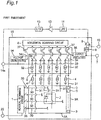
- FIG. 1 is a circuit diagram showing a configuration example of a thermal infrared solid-state imaging element according to a first embodiment of the present invention.
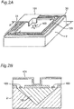
- FIG. 2A is a perspective view showing an appearance of a photosensitive pixel 2 of FIG. 1
- FIG. 2B is a longitudinal cross-sectional view taken along line A-A' of FIG. 2A .
- the thermal infrared solid-state imaging element according to the first embodiment is a configured such that, in a manner similar to that of a thermal infrared solid-state imaging element according to the prior art, a plurality of photosensitive pixels 2 are arranged in a lattice shape in a two-dimensional shape so as to form a photosensitive pixel array 2A.
- each of photosensitive pixels 2 is configured to include a plurality (which may be at least one) of diodes 100 connected in series. As shown in FIGS. 2A and 2B , the photosensitive pixel 2 is formed by forming a supporting leg 103 on a heat insulating layer 102, and forming an infrared ray absorption member 101 on the supporting leg 103.
- a driving line 30 is commonly connected for each of rows of a predetermined number of the photosensitive pixels 2, while a signal line 31 is commonly connected for each of columns of a predetermined number of the photosensitive pixels 2.
- An end of each of signal lines 31 is connected with a first constant current source 4 as a first group of constant current source means, and also connected to an inverting input terminal of a differential integration circuit 34.
- the driving line 30 is sequentially selected by a vertical scanning circuit 1 and a plurality of vertical selection switches 35, and each of driving lines 30 is sequentially connected to a power supply terminal 22.
- a second constant current source 32 configured to allow substantially the same current as the first constant current source 4 to flow, and a plurality of the second constant current sources 32 are connected in parallel by a bias line 33 that is substantially parallel to the driving line 30.
- the bias line 33 has substantially the same resistance value as that of the driving line 30 to generate a voltage drop substantially the same as that of the driving line 30, and is connected to a non-inverting output terminal of each of differential integration circuits 34.
- the bias line 33 has substantially the same voltage effect as that of the driving line 30, and does not necessarily have the same resistance as that of the driving line 30.
- the bias line 33 and the driving line 30 may have different resistances, accordingly.
- the differential integration circuit 34 is provided for each of rows of the photosensitive pixels 2, and the differential integration circuit 34 time-integrates and amplifies a difference between a voltage across the first constant current source 4 and a voltage across the second constant current source 32 with a predetermined integration interval.
- a signal voltage of the pixel signal resulting from the integration and amplification is output via an output amplifier 36 and a plurality of horizontal selection switches 37 configured to include, for example, transistors.
- the plurality of horizontal selection switches 37 are sequentially turned ON by a horizontal scanning circuit 6, and an output signal of the differential integration circuit 34 arranged for each of columns is output as a pixel signal to an external circuit from an image signal output terminal 7 via the output amplifier 36. Since substantially the same voltage drop as that of the driving line 30 occurs in the bias line 33, the voltage drop in the driving line 30 is canceled from the output voltage by the above configuration, and an offset distribution derived from the driving line 30 is removed.
- the differential integration circuit 34 at the right end of FIG. 1 generates a differential signal between a voltage of the bias line 33 and a reference signal that reflects an element temperature and is output from a reference pixel 3 of a reference pixel array 3A (reference signal output circuit) provided in the photosensitive pixel array 2A or outside the photosensitive pixel array 2A. Further, via the output amplifier 36 and a sample-and-hold circuit 8, the differential integration circuit 34 outputs the differential signal to the inverting input terminal of a bias generating circuit 9 that is configured to include a differential amplifier circuit.
- the bias generating circuit 9 compares the differential signal with a predetermined reference voltage 10, generates a bias voltage corresponding to the difference, and feeds back to the bias line 33 via a low-pass filter 11, a buffer amplifier 12, and a low-pass filter 13. With the loop circuit described above, it is possible to automatically correct voltage variation of the bias line due to manufacturing variations or the like while changing the voltage of the bias line 33 according to the reference signal (that is, according to the element temperature).
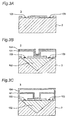
- FIGS. 3A to 3E are longitudinal cross-sectional views showing a configuration of the reference pixel 3 of FIG. 1 according to the first to fifth implementation examples, respectively.
- the reference pixel 3 is formed by removing at least one of the heat insulating layer 102 and the infrared ray absorption member 101 from the photosensitive pixel 2, or adding an infrared ray shielding layer 104.
- the structure of the reference pixel array 3A of FIGS. 3A to 3E may be applied to other embodiments and their modified embodiments other than the first embodiment.
- the reference pixel 3 may be formed by removing the infrared ray absorption member 101 and the heat insulating layer 102 from the structure of FIGS. 2A and 2B .
- the reference pixel 3 may be formed by merely adding the infrared ray shielding layer 104 directly to the infrared ray absorption member 101 in the structure of FIGS. 2A and 2B .
- the reference pixel 3 may be formed such that the infrared ray shielding layer 104 covers the entire pixel with respect to the structure of FIGS. 2A and 2B .
- the reference pixel 3 may be formed by removing the infrared ray absorption member 101 and forming the infrared ray shielding layer 104 in the structure of FIGS. 2A and 2B .
- the reference pixel 3 may be formed with the structure shown in FIG. 3E .
- the reference pixel 3 is formed by removing the infrared ray absorption member 101 from the structure of FIGS. 2A and 2B .
- a filter that inhibits incoming infrared rays may be installed on a front face of the thermal infrared solid-state imaging element (upper side on the plane of drawing of FIG. 1 ).
- a voltage across the first constant current source 4 connected to the reference pixel 3 is read out as a reference signal.
- This reference signal is read out in a manner similar to that of a path of a normal output signal of the photosensitive pixel 2. That is, the voltage across the first constant current source 4 connected to the reference pixel 3 is input to the inverting input terminal of the differential integration circuit 34 at the right end of FIG. 1 , the voltage across the second constant current source 32 that is adjacent to the differential integration circuit 34 and connected to the bias line 33 is input to a non-inverting input terminal of the differential integration circuit 34.
- This differential integration circuit 34 integrates, amplifies, and outputs the difference between the two input voltages.
- the output signal is read out as an output signal corresponding to the reference pixel 3 for each of lines of normal image reading by the horizontal scanning circuit 6 and the horizontal selection switch 37, and is output from the image signal output terminal 7 via the output amplifier 36.
- the sample-and-hold circuit 8 is connected to the image signal output terminal 7, and the sample-and-hold circuit 8 samples and holds the output signal of the reference pixel 3. Then, the sampled and held signal voltage is input to the inverting input terminal of the bias generating circuit 9 configured to include a differential amplifier circuit, while the reference voltage 10 is input to the non-inverting input terminal of the bias generating circuit 9.
- the bias generating circuit 9 generates and outputs a bias voltage corresponding to the difference between the two input voltages.
- the generated bias voltage is generated as the output level stabilized voltage 14a via the low-pass filter 11, the buffer amplifier 12, and the low-pass filter 13, and the output level stabilized voltage 14a is applied to the bias line 33.
- the sample-and-hold circuit 8 samples and holds the output signal of the reference pixel 3.
- the bias voltage may be determined by sampling and holding an output voltage of one pixel per screen.
- an output voltage of a plurality of pixels per screen may be averaged by sampling and holding.
- a subtractive polarity of the differential integration circuit 34 and a subtractive polarity of the bias generating circuit 9 are selected in such a direction that a change in the output signal corresponding to the reference pixel 3 is suppressed. That is, when a voltage of the bias line 33 (a voltage of the current source 32 connected to the bias line 33) is input to the non-inverting input terminal of the differential integration circuit 34, an output voltage from the differential integration circuit 34 is input to the inverting input terminal of the bias generating circuit 9.
- the bias generating circuit 9 changes the voltage of the bias line 33 into a direction to decrease this difference according to the difference between the sampled and held signal voltage and the reference voltage 10.
- the output level stabilized voltage 14a is directly applied to the bias line 33 via the low-pass filter 11, the buffer amplifier 12, and the low-pass filter 13. Since the output level stabilized voltage 14a maintains the signal level of the reference pixel 3 at a constant level, the pixel signal does not include the substrate temperature information, while the output level stabilized voltage 14a includes the temperature signal.
- the thermal infrared solid-state imaging element of the present embodiment applies the output level stabilized voltage 14a to a voltage generating circuit 14, and the voltage generating circuit 14 generates and outputs a voltage component of a temperature signal generation voltage 14c so as to be added to the image signal output terminal 7 via the horizontal selection switch 37 and the output amplifier 36.
- FIG. 4 is a circuit diagram showing a configuration example of the voltage generating circuit 14 of FIG. 1 .
- FIG. 11 is a schematic waveform chart showing a voltage level of each of terminals of the voltage generating circuit 14 of FIG. 4 .
- the output level stabilized voltage 14a changes in accordance with a substrate temperature.
- the substrate temperature is strongly influenced by an ambient temperature and is also influenced by slight temperature changes such as an element operation cycle. Therefore, when acquiring the substrate temperature, it is preferable to acquire temperature information during an operation interval of the differential integration circuit 34, that is, a pixel operation interval.
- a signal voltage of a pixel signal 50 is set within an output A/D conversion range of the pixel signal, whereas the output level stabilized voltage 14a is not necessarily set in this pixel signal output A/D conversion range.
- a first level shift circuit 40 converts the output level stabilized voltage 14a into a first generated voltage 14d, and outputs to a sample-and-hold circuit 41 so as to level-shift the output level stabilized voltage 14a within the pixel signal A/D conversion range at the image signal output terminal 7.
- a level shift amount adjustment voltage 42 may be input to the first level shift circuit 40.
- the sample-and-hold circuit 41 samples and holds the input first generated voltage 14d in an operation interval according to an operation interval signal 51 indicating the operation interval of the differential integration circuit 34, to generate the temperature signal generation voltage 14c. This enables acquisition of the substrate temperature in synchronization with a timing of acquiring the pixel signal.
- FIG. 12 is a schematic waveform chart showing an output voltage of the voltage generating circuit 14 of FIG. 4 .
- the temperature signal generation voltage 14c is output to the image signal output terminal 7. That is, the temperature signal generation voltage 14c and the pixel signal are applied on the same signal as the pixel signal 50 at different timings.
- the voltage generating circuit 14 of FIG. 1 is not limited to the above circuit configuration, as long as the stabilized voltage 14a is level-shifted within a pixel signal output range, and temperature information synchronized with a temperature signal acquisition interval can be acquired.
- the newly provided voltage generating circuit 14 generates a temperature signal generation voltage with the output level in the same range as that of the pixel signal. Outputting this temperature signal generation voltage to the image signal output terminal 7 enables acquisition of temperature information by the A/D converter same as that for image acquisition, which does not result in an increase in power consumption and an increase in circuit scale.
- the infrared imaging element includes: the photosensitive pixel array 2A having the heat insulating layer 102 and the infrared ray absorption member 101, and having the plurality of photosensitive pixels 2 arranged in a two-dimensional shape; the driving line 30 commonly connected with one pole of each of the photosensitive pixels 2 for each of rows; the vertical scanning circuit 1 configured to sequentially select the driving line 30 and connect the driving line 30 to a power supply; the signal line 31 commonly connected with another pole of each of the photosensitive pixels 2 for each of columns, and having an end part connected with the first constant current source 4; the bias line 33 that is connected in parallel with the second constant current source 32 provided for each of columns of the photosensitive pixel array 2A, and generates substantially the same voltage drop as that of the driving line 30; the differential integration circuit 34 that is provided for each of columns of the photosensitive pixel array 2A, and time-integrates and outputs a difference between a voltage across the first constant current source 4 and a voltage
- the infrared imaging element includes: the reference pixel array 3A that outputs a reference signal that changes substantially in accordance with a change in a temperature of the whole of the plurality of photosensitive pixels 2; the bias generating circuit 9 configured to generate a bias voltage to apply the bias voltage to the bias line, the bias voltage corresponding to a difference between a predetermined reference voltage and a differential signal between the reference signal and a voltage at a predetermined position on the bias line, and the bias voltage including a voltage component of the output level stabilized voltage; and the voltage generating circuit 14 configured to generate a predetermined temperature signal generation voltage based on the bias voltage, and to add the generated temperature signal generation voltage to the image signal output terminal.
- the newly provided voltage generating circuit 14 generates a temperature signal generation voltage with the output level in the same range as that of the pixel signal. Applying this temperature signal generation voltage to the image signal output terminal 7 enables acquisition of temperature information by the A/D converter 16a ( FIGS. 9 and 10 ) same as that for image signal acquisition, which does not result in an increase in power consumption and an increase in circuit scale. At the same time, the image information and the temperature information are synchronously output, facilitating various corrections of the image signal in the image signal processing circuit in a subsequent stage.
- the reference pixel array 3A is formed to remove either one or both of the heat insulating layer 102 and the infrared ray absorption member 101, or is formed to have the infrared ray shielding layer 104.
- the photosensitive pixel array 2A is formed to remove either one or both of the heat insulating layer 102 and the infrared ray absorption member.
- the reference pixel array 3A is formed so as to be adjacent to at least one side in a vertical direction or a horizontal direction of the photosensitive pixel array 2A.
- the reference pixel array 3A includes a plurality of reference pixels 3, and the infrared imaging element further includes the sample-and-hold circuit 8 that is provided in a preceding stage of the bias generating circuit 9, samples and holds pixel signals from the plurality of reference pixels 3 after averaging the pixel signals, and then outputs the sampled and held pixel signals to the bias generating circuit 9. Therefore, averaging the output signals from the plurality of reference pixels 3 enables stabilization of an output level stabilized voltage 14b, which consequently provides a stabilized output level of the image signal.
- the temperature signal generation voltage 14c is adjusted so as to become a predetermined voltage together with the voltage level of the image signal, and is configured to be added to the image signal at a timing different from that of the pixel signal.
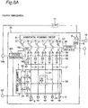
- FIG. 5 is a circuit diagram showing a configuration example of a thermal infrared solid-state imaging element according to a second embodiment of the present invention.
- the thermal infrared solid-state imaging element according to the second embodiment of FIG. 5 differs from the thermal infrared solid-state imaging element according to the first embodiment of FIG. 1 in the following points.
- the output level stabilized voltage 14a is directly applied to the bias line 33 via the low-pass filter 11, a buffer amplifier 12, and the low-pass filter 13.
- the output level stabilized voltage 14a applied to the bias line 33 is amplified by a differential integration circuit having a high degree of amplification (in many cases, a gain of 10 or more), and further amplified by an amplifier circuit inside a camera incorporated with the element, highly accurate setting is necessary.
- FIG. 13 is a chart showing a relationship between various voltage levels and an inherent noise component in a thermal infrared solid-state imaging element according to a comparison example, and is a schematic waveform chart showing a voltage level of each of terminals.
- FIG. 13 shows a relationship among a power supply terminal voltage 52 applied to the power supply terminal 22, the output level stabilized voltage 14a, a voltage across the first constant current source 4, and a voltage across a second constant current source 32.
- the output level stabilized voltage 14a changes in accordance with a substrate temperature
- the substrate temperature is strongly influenced by an ambient temperature and is also influenced by slight temperature changes such as an element operation cycle.
- various noises are also applied to a circuit of a path leading to the bias line 33 including the bias generating circuit 9 and the buffer amplifier 12.
- a noise component also exists in the power supply terminal voltage 52 applied to the power supply terminal 22, a noise component also exists. In this case, the noise components existing in the output level stabilized voltage 14a and the power supply terminal voltage 52 are not necessarily synchronized with each other.
- the voltage across the first constant current source 4 is generated from the power supply terminal voltage 52 via wiring of a vertical scanning circuit 1, a driving line 30, a diode 100, and the signal line 31. Since a voltage drop occurs in each of the paths, a voltage level across the first constant current source 4 becomes lower than that of the power supply terminal voltage 52. In addition, the voltage across the first constant current source 4 has a synthesized noise of the noise component in each of the paths and the noise component inherent in the power supply terminal voltage 52.
- the voltage across the second constant current source 32 is generated from the output level stabilized voltage 14a via the bias line 33.
- a voltage level of the second constant current source 32 becomes lower than that of the output level stabilized voltage 14a.
- the voltage across the second constant current source 32 has a synthesized noise of the noise component that generates in the bias line 33 and the noise component inherent in the output level stabilized voltage 14a.
- the noise components are not synchronized with each other, and a sum of the noise of the two types of signals is output in the output voltage from the differential integration circuit 34.
- the thermal infrared solid-state imaging element according to the present embodiment solves these problems and will be described in detail below.
- FIGS. 6A to 6D are block diagrams showing a configuration example of the voltage generating circuit 14A of FIG. 5 according to the first to fourth implementation examples, respectively.
- FIG. 14 is a schematic waveform chart showing an output voltage level of the voltage generating circuit 14A of FIG. 6A .
- the voltage generating circuit 14A of FIG. 6A is configured to include a first level shift circuit 40, a sample-and-hold circuit 41, a second level shift circuit 43, a noise component application circuit 44, and a buffer amplifier 45.
- the output level stabilized voltage 14a is input to the first level shift circuit 40 and the second level shift circuit 43.
- the voltage output from the first level shift circuit 40 is subjected to voltage stabilization by the sample-and-hold circuit 41 in a manner similar to that of the first embodiment, and is generated as the temperature signal generation voltage 14c.
- the temperature signal generation voltage 14c is output to the image signal output terminal 7 via the horizontal selection switch 37.
- the output level stabilized voltage 14a is level-shifted by the second level shift circuit 43 to generate a second generated voltage 14e.
- a circuit gain (a gain of the output level stabilized voltage 14b with respect to the input voltage) in the second level shift circuit 43 to more than 0 and 1 or less, the noise component inherent in the output level stabilized voltage 14a is suppressed.
- the second generated voltage 14e is input to the noise component application circuit 44, and a noise component inherent in the power supply terminal voltage 52 is applied from the power supply terminal 22, generating a third generated voltage 14f.
- the third generated voltage 14f is output via the buffer amplifier 45, and the buffer amplifier 45 generates the output level stabilized voltage 14b, and outputs to the bias line 33.
- These circuit configurations consequently suppress the noise component inherent in the output stabilized voltage 14a in the output level stabilized voltage 14b, and applies a noise component synchronized with the power supply terminal voltage 52, which is a power supply voltage (hereinafter, referred to as a driving power supply voltage) that drives a photosensitive pixel 2 of a photosensitive pixel array 2A.
- Two types of voltage signals applied to the differential integration circuit 34 that is, the voltage across the first constant current source 4 and the voltage across the second constant current source 32 are determined by the power supply terminal voltage 52 and the output level stabilized voltage 14b. Therefore, these two types of voltage signals have a noise component synchronized with the driving power supply voltage.
- the output voltage of the differential integration circuit 34 has an effect of canceling a noise component synchronized with the driving power supply voltage, a common mode noise suppression effect can be obtained. As a result, the noise component at the image signal output terminal 7 is to be suppressed.
- a circuit gain (a gain of the output level stabilized voltage 14b with respect to the input voltage) in a current path from the second level shift circuit 43 to the buffer amplifier 45 is set to be more than 0 and 1 or less. This suppresses the noise component inherent in the output level stabilized voltage 14a, and consequently suppresses the noise component in the image signal output terminal 7.
- the output level stabilized voltage 14b applied to the bias line 33 becomes highly accurate by the reciprocal of the circuit gain of the voltage generating circuit 14A.
- temperature information can be acquired by an A/D converter same as that for image acquisition, maintaining the effect of not increasing the power consumption and not increasing the circuit scale.
- the image information and the temperature information are synchronously output, also maintaining the effect of facilitating various corrections in the signal processing circuit.
- the voltage generating circuit 14A is not limited to the circuit configuration shown in FIG. 6A , as long as the voltage generating circuit 14A has a function of, based on the output level stabilized voltage 14a, generating the temperature signal generation voltage 14c, which is a stable voltage level-shifted within the pixel signal output range, and a function of, based on the output level stabilized voltage 14a, generating the output level stabilized voltage 14b that is applied with a noise component synchronized with the driving power supply voltage input to the power supply terminal 22 and has a fluctuation width subjected to attenuation processing.
- a modified embodiment will be described below.
- the noise component application circuit 44 may be omitted by providing a function of the noise component application circuit 44 of FIG. 6A , which is to apply the noise component from the power supply terminal 22.
- the output stabilized voltage 14a is input to a third level shift circuit 46, and a voltage obtained from the output voltage from the third level shift circuit 46 via the buffer amplifier 45 is resistively divided by a first resistor 47 and a second resistor 48. A voltage obtained at a connection point of the first resistor 47 and the second resistor 48 is sampled and held by the sample-and-hold circuit 41, to provide the temperature signal generation voltage 14c.
- a voltage obtained from an output voltage of the buffer amplifier 45 via the first resistor 47 and the second resistor 48 is generated as the output level stabilized voltage 14b.
- a switch SW may be additionally inserted between the power supply terminal 22, and the second level shift circuit 43 and the buffer amplifier 45, as compared with the voltage generating circuit 14A of FIG. 6B .
- the voltages applied to the second level shift circuit 43 and the buffer amplifier 45 may be ON/OFF controlled by the switch SW based on a predetermined control signal.
- the ON timing is a timing at which infrared detection is being performed (an integration interval of the differential integration circuit 34 of FIG. 1 or the like, which is a drive timing of the voltage generating circuit 14A of FIG. 6D ), that is, synchronized with a vertical selection switch 35.
- This causes power consumption in the voltage generating circuit 14A to be limited only to the ON interval, providing a power consumption suppression effect.
- the voltage generating circuit 14A has a buffer function, it is sufficient to insert only the low-pass filter 11 between the bias generating circuit 9 and the voltage generating circuit 14A, eliminating necessity of the buffer amplifier 12 and the low-pass filter 13. This enables removal of the noise component that generates in the buffer amplifier 12 in the output level stabilized voltage 14a, providing effect of reducing noise in the output signal. At the same time, power consumption in the buffer amplifier 12 becomes unnecessary, enabling low power consumption and suppression of manufacturing cost.
- the voltage generating circuit 14A based on the bias voltage and the input voltage from the power supply terminal 22, the voltage generating circuit 14A generates and adds the temperature signal generation voltage 14c to the image signal output terminal 7, and generates and applies the output level stabilized voltage 14b to the bias line 33.
- the second embodiment and its modified embodiment have the function and effect similar to the first embodiment, and it is possible to add a noise component having the same phase as a driving voltage of the photosensitive pixel to the output level stabilized voltage 14b, and effectively provide the common mode noise suppression effect in the differential integration circuit 34.
- the voltage generating circuit 14 is configured to be driven during the integration interval of the differential integration circuit 34. Therefore, the power consumption in the voltage generating circuit 14 is limited only to the ON interval, providing a power consumption suppression effect.
- the output level stabilized voltage 14b includes a noise component synchronized with the driving power supply voltage that drives the photosensitive pixel 2. Therefore, by adding a noise component having the same phase as the driving power supply voltage to the output level stabilized voltage 14b, the common mode noise suppression effect in the differential integration circuit 34 can be effectively obtained.
- the circuit gain of the output level stabilized voltage 14b with respect to the input voltage in the voltage generating circuit 14 is set to be more than 0 and 1 or less. This can enhance controllability of the output level stabilized voltage 14b and suppress the influence of the noise component included in the output level stabilized voltage 14b on the pixel output signal.
- the low-pass filter 11 that low-pass filters the bias voltage from the bias generating circuit 9, and outputs the bias voltage to the voltage generating circuit 14. Therefore, when providing the buffer function to the voltage generating circuit 14, it is sufficient to provide only the low-pass filter 11 between the bias generating circuit 9 and the voltage generating circuit 14, eliminating necessity of the buffer amplifier 12 and the low-pass filter 13 of FIG. 1 . This enables removal of the noise component that generates in the buffer amplifier 12 in the output level stabilized voltage 14a, providing effect of reducing noise in the output signal.
- FIG. 7A is a circuit diagram showing a configuration example of a thermal infrared solid-state imaging element according to a third embodiment of the present invention.
- FIG. 7B is a circuit diagram showing a configuration example of a thermal infrared solid-state imaging element according to a first modified embodiment of the third embodiment of the present invention.
- FIG. 7C is a circuit diagram showing a configuration example of a thermal infrared solid-state imaging element according to a second modified embodiment of the third embodiment of the present invention.
- the reference pixel array 3A described in the first and second embodiments is not limited to the one column on the right side as shown in FIG. 1 , as long as a temperature of a reference pixel 3 is equivalent to a temperature of a photosensitive pixel 2 of a photosensitive pixel array 2A.
- a reference pixel array 3A may be arranged as one row on a lower side, or may be arranged at any one pixel as shown in FIG. 7B .
- the reference pixel array 3A may be arranged outside the photosensitive pixel array 2A as shown in FIG. 7C .
- averaging signal voltages of pixel signals from a plurality of the photosensitive pixels 2 allows stabilization of the output level stabilized voltage 14a, and consequently, the effect of obtaining a stabilized output level of the image signal can be obtained.
- FIG. 8A is a circuit diagram showing a configuration example of a thermal infrared solid-state imaging element according to a fourth embodiment of the present invention.
- FIG. 8B is a circuit diagram showing a configuration example of a thermal infrared solid-state imaging element according to a modified embodiment of the fourth embodiment of the present invention.
- the first constant current source 4 of FIG. 1 shown in the first embodiment and in FIG. 5 shown in the second embodiment is provided at the end of each of the signal lines 31, but the present invention is not limited to such an arrangement.
- a first constant current source 4 may be provided at a position opposed to a second constant current source 32 with a photosensitive pixel 2 interposed therebetween.
- a voltage at a connection point of the photosensitive pixel 2 to the signal line 31 is input to the differential integration circuit 34.
- the voltage signal input to the differential integration circuit 34 in FIGS. 1 and 5 includes a voltage drop component in the signal line 31, but the voltage drop component is not included in this configuration. Since it is possible to obtain an output voltage of a pixel signal from which variation components such as a manufacturing variation and a voltage drop amount change when a temperature component changes are removed, the pixel signal level can be stabilized.
- the voltage from the power supply terminal 22 may be input from upper and lower ends of a vertical scanning circuit 1.
- This circuit configuration enhances uniformity of the voltage input to the driving line 30 in each of rows, so that the pixel signal level can be stabilized.
- the input is from the upper and lower two points of FIG. 8B , the present invention is not limited to this.
- the pixel signal level can be further stabilized by including the input in the middle of the vertical scanning circuit 1 and allowing multi-point input.
- the first constant current source 4 and the second constant current source 32 are provided so as to sandwich a photosensitive pixel array 2A. Therefore, the voltage signal input to the differential integration circuit 34 does not include the voltage drop component in the signal line 31. As a result, since it is possible to output a pixel signal from which variation components such as a manufacturing variation and a voltage drop amount change when a temperature component changes are removed, the output signal can be stabilized.
- FIG. 9 is a block diagram showing a configuration example of an image correction circuit of a thermal infrared solid-state imaging element according to a comparison example.
- an image correction circuit 17 is configured to include a temperature signal variation amount determination circuit 18, a correction signal generating circuit 19, and an image signal synthesizing circuit 20, and a memory 21 that holds correction data according to a temperature change is connected to the correction signal generating circuit 19 and the image signal synthesizing circuit 20 in advance.
- FIG. 9 there is an image signal A/D converter 16a as means to read an image signal, and there is a temperature signal A/D converter 16b as means to read a temperature signal.
- the temperature signal variation amount determination circuit 18 determines a substrate temperature, and outputs the determination result to the correction signal generating circuit 19.
- the correction signal generating circuit 19 generates a correction signal based on the input determination result and correction data from the memory 21, and outputs the correction signal to the image signal synthesizing circuit 20.
- the image signal synthesizing circuit 20 corrects the image signal read out by the image signal A/D converter 16a using the correction signal, to synthesize and output the corrected image signal. Accordingly, a stable image output can be obtained even when the temperature changes.
- FIG. 10 is a block diagram showing a configuration example of an image correction circuit of a thermal infrared solid-state imaging element according to a fifth embodiment of the present invention.
- the thermal infrared solid-state imaging element of FIG. 1 shown in the first embodiment and shown in the second embodiment, a temperature signal can be added to the pixel signal. Therefore, the temperature signal A/D converter 16b can be omitted as compared with the comparison example of FIG. 9 , as shown in FIG. 10 . As a result, the image correction circuit 17 can collectively determine the image signal and the temperature signal based on the image signal read out from the image signal A/D converter 16a.
- an image signal is corrected and synthesized by using the temperature signal variation amount determination circuit 18, the memory 21, the correction signal generating circuit 19, and the image signal synthesizing circuit 20, in a manner similar to that of FIG. 9 .
- this configuration it is possible to improve the effect of obtaining a stable image output even when the temperature changes, and to prevent an increase in power consumption and manufacturing cost and an increase in circuit scale.
- an infrared imaging element provided with the image correction circuit of FIG. 10 , and an infrared camera that performs predetermined image signal processing on an image signal from the infrared imaging element, and stores image signal data in an image memory.
- an image signal including a temperature signal generation voltage it is possible to generate an image signal including a temperature signal generation voltage. Therefore, for example, it is possible to acquire temperature information by the A/D converter same as that for acquisition of an image signal, resulting in neither an increase in power consumption nor an increase in circuit scale. At the same time, both the image information and the temperature information are output, facilitating various image corrections in an image signal processing circuit in a subsequent stage.
Landscapes
- Engineering & Computer Science (AREA)
- Multimedia (AREA)
- Signal Processing (AREA)
- Physics & Mathematics (AREA)
- General Physics & Mathematics (AREA)
- Spectroscopy & Molecular Physics (AREA)
- Transforming Light Signals Into Electric Signals (AREA)
- Photometry And Measurement Of Optical Pulse Characteristics (AREA)
Claims (13)
- Infrarot-Abbildungselement, das Folgendes aufweist:- eine photosensitive Pixelmatrix (2A), die eine wärmeisolierende Schicht (102) und ein Infrarotstrahlungs-Absorptionselement (101) aufweist, wobei die photosensitive Pixelmatrix (2A) eine Vielzahl von photosensitiven Pixeln (2) aufweist, die in einer zweidimensionalen Form angeordnet sind;- eine Ansteuerleitung (30), die gemeinsam mit einem Pol von jedem der photosensitiven Pixeln (2) für jede Zeile verbunden ist;- eine Vertikalabtastschaltung (1), die dazu ausgebildet ist, die Ansteuerleitung (30) sequentiell auszuwählen, um die Ansteuerleitung (30) mit einer Stromversorgung zu verbinden;- eine Signalleitung (31), die gemeinsam mit einem anderen Pol von jedem der photosensitiven Pixel (2) für jede Spalte verbunden ist, wobei die Signalleitung einen Endbereich aufweist, der mit einer ersten Konstantstromquellen-Einrichtung (4) verbunden ist;- eine Vorspannungsleitung (33), die parallel zu einer zweiten Konstantstromquellen-Einrichtung (32) geschaltet ist, die für jede der Spalten der photosensitiven Pixelmatrix (2A) angeordnet ist, wobei die Vorspannungsleitung (33) dazu ausgebildet ist, einen Spannungsabfall zu erzeugen, der im Wesentlichen identisch zu dem der Ansteuerleitung (30) ist;- eine Differentialintegrationsschaltung (34), die für jede der Spalten der photosensitiven Pixelmatrix (2A) angeordnet ist, wobei die Differentialintegrationsschaltung (34) zur Zeit-Integration und zum Ausgeben einer Differenz zwischen einer Spannung an der ersten Konstantstromquellen-Einrichtung (4) und einer Spannung an der zweiten Konstantstromquellen-Einrichtung (32) mit einer vorbestimmten Integrationszeit ausgebildet ist;- eine Horizontalabtastschaltung (6), die dazu ausgebildet ist, ein Ausgangssignal der Differentialintegrationsschaltung (34) für jede der Spalten auszuwählen, um das Ausgangssignal als Bildsignal zu einem Bildsignal-Ausgangsanschluss (7) zu übertragen;- eine Referenzpixelmatrix (3A), die dazu ausgebildet ist, ein Referenzsignal auszugeben, das sich im Wesentlichen in Abhängigkeit von einer Änderung der Temperatur der Gesamtheit der Vielzahl von photosensitiven Pixeln (2) ändert;eine Vorspannungs-Erzeugungsschaltung (9), die dazu ausgebildet ist, eine Vorspannung zum Anlegen der Vorspannung an die Vorspannungsleitung (33) zu erzeugen, wobei die Vorspannung einer Differenz zwischen einer vorbestimmten Referenzspannung und einem Differentialsignal zwischen dem Referenzsignal und einer Spannung an einer vorbestimmten Position auf der Vorspannungsleitung (33) entspricht,
dadurch gekennzeichnet,
dass die Vorspannung eine Spannungskomponente einer ausgangspegelstabilisierten Spannung (14b) aufweist; und
dass eine Spannungs-Erzeugungsschaltung (14, 14A) angeschlossen ist, die dazu ausgebildet ist, eine vorbestimmte Temperatursignal-Erzeugungsspannung (14c) basierend auf der Vorspannung zu erzeugen und die vorbestimmte Temperatursignal-Erzeugungsspannung (14c) zu dem Bildsignal-Ausgangsanschluss (7) hinzuzufügen. - Infrarot-Abbildungselement nach Anspruch 1,
wobei die Spannungs-Erzeugungsschaltung (14, 14A) dazu ausgebildet ist, die Temperatursignal-Erzeugungsspannung (14c) basierend auf der Vorspannung und einer Eingangsspannung von einem Stromversorgungsanschluss (22) zu erzeugen, und die Temperatursignal-Erzeugungsspannung (14c) zu dem Bildsignal-Ausgangsanschluss (7) hinzuzufügen, und wobei die Spannungs-Erzeugungsschaltung (14, 14A) ferner dazu ausgebildet ist, eine ausgangspegelstabilisierte Spannung (14b) zu erzeugen und die ausgangspegelstabilisierte Spannung an die Vorspannungsleitung (33) anzulegen. - Infrarot-Abbildungselement nach Anspruch 1 oder 2,
wobei die Referenzpixelmatrix (3A) dazu ausgebildet ist, entweder die wärmeisolierende Schicht (102) oder das Infrarotstrahlungs-Absorptionselement (101) oder beide zu entfernen, oder so ausgebildet ist, dass sie eine Infrarotstrahlungs-Abschirmschicht (104) aufweist. - Infrarot-Abbildungselement nach einem der Ansprüche 1 bis 3,
wobei die photosensitive Pixelmatrix (2A) dazu ausgebildet ist, entweder die wärmeisolierende Schicht (102) oder das Infrarotstrahlungs-Absorptionselement (101) oder beide zu entfernen. - Infrarot-Abbildungselement nach einem der Ansprüche 1 bis 4,
wobei die Referenzpixelmatrix (3A) so ausgebildet ist, dass sie in vertikaler Richtung oder in horizontaler Richtung an mindestens eine Seite der photosensitiven Pixelmatrix (2A) angrenzt. - Infrarot-Abbildungselement nach einem der Ansprüche 1 bis 5,
wobei die Referenzpixelmatrix (3A) eine Vielzahl von Referenzpixeln (3) aufweist, und
wobei das Infrarot-Abbildungselement ferner eine Abtast-und-HalteSchaltung (41) aufweist, die in einer vorhergehenden Stufe der Vorspannungs-Erzeugungsschaltung (9) angeordnet ist, Pixelsignale abtastet und dazu ausgebildet ist, die Pixelsignale von der Vielzahl von Referenzpixeln (3) nach einer Mittelwertbildung der Pixelsignale zu halten, und die abgetasteten und gehaltenen Pixelsignale an die Vorspannungs-Erzeugungsschaltung (9) auszugeben. - Infrarot-Abbildungselement nach einem der Ansprüche 1 bis 6,
wobei die erste Konstantstromquellen-Einrichtung (4) und die zweite Konstantstromquellen-Einrichtung (32) so angeordnet sind, dass sie die photosensitive Pixelmatrix (2A) sandwichartig umgeben. - Infrarot-Abbildungselement nach einem der Ansprüche 1 bis 7,
wobei die Temperatursignal-Erzeugungsspannung (14c) so angepasst ist, dass sie zusammen mit einem Spannungspegel des Bildsignals eine vorbestimmte Spannung ergibt, und so ausgebildet ist, dass sie dem Bildsignal zu einem Zeitpunkt hinzugefügt wird, der sich von dem des Bildsignals unterscheidet. - Infrarot-Abbildungselement nach einem der Ansprüche 1 bis 8,
wobei die Spannungs-Erzeugungsschaltung (14, 14A) so ausgebildet ist, dass sie während eines Integrationsintervalls der Differentialintegrationsschaltung angesteuert wird. - Infrarot-Abbildungselement nach Anspruch 2,
wobei die ausgangspegelstabilisierte Spannung (14b) eine Rauschkomponente aufweist, die mit einer Ansteuerungsenergie-Versorgungsspannung synchronisiert ist, die dazu ausgebildet ist, die photosensitiven Pixel (2) anzusteuern. - Infrarot-Abbildungselement nach Anspruch 2 oder 10,
wobei eine Schaltungsverstärkung der ausgangspegelstabilisierten Spannung (14b) bezogen auf eine Eingangsspannung in der Spannungs-Erzeugungsschaltung (14, 14A) mit größer als 0 und kleiner gleich 1 vorgegeben wird. - Infrarot-Abbildungselement nach Anspruch 2, 10 oder 11,
das ferner einen Tiefpassfilter (11) aufweist, der dazu ausgebildet ist, die Vorspannung mit einem Tiefpass zu filtern und die Vorspannung an die Spannungs-Erzeugungsschaltung auszugeben. - Infrarotkamera, die Folgendes aufweist:- ein Infrarot-Abbildungselement nach einem der Ansprüche 1 bis 12; und- eine Bildkorrekturschaltung (17), die dazu ausgebildet ist, ein Ausgangsbildsignal basierend auf einem Bildsignal so zu korrigieren, dass es konstant ist, wobei das Bildsignal von dem Infrarot-Abbildungselement ausgegeben wird und die Temperatursignal-Erzeugungsspannung (14c) enthält.
Applications Claiming Priority (2)
| Application Number | Priority Date | Filing Date | Title |
|---|---|---|---|
| JP2016083354 | 2016-04-19 | ||
| PCT/JP2017/004434 WO2017183260A1 (ja) | 2016-04-19 | 2017-02-07 | 赤外線撮像素子及び赤外線カメラ |
Publications (3)
| Publication Number | Publication Date |
|---|---|
| EP3447461A1 EP3447461A1 (de) | 2019-02-27 |
| EP3447461A4 EP3447461A4 (de) | 2019-05-01 |
| EP3447461B1 true EP3447461B1 (de) | 2020-04-01 |
Family
ID=60115875
Family Applications (1)
| Application Number | Title | Priority Date | Filing Date |
|---|---|---|---|
| EP17785605.1A Active EP3447461B1 (de) | 2016-04-19 | 2017-02-07 | Infrarotabbildungselement und infrarotkamera |
Country Status (5)
| Country | Link |
|---|---|
| US (1) | US10848689B2 (de) |
| EP (1) | EP3447461B1 (de) |
| JP (1) | JP6715922B2 (de) |
| CN (1) | CN109073458B (de) |
| WO (1) | WO2017183260A1 (de) |
Families Citing this family (6)
| Publication number | Priority date | Publication date | Assignee | Title |
|---|---|---|---|---|
| JP7132235B2 (ja) * | 2017-10-31 | 2022-09-06 | ソニーセミコンダクタソリューションズ株式会社 | 撮像装置 |
| WO2019234966A1 (ja) * | 2018-06-06 | 2019-12-12 | 三菱電機株式会社 | 赤外線撮像素子およびそれを備えた空気調和機 |
| FR3082385B1 (fr) * | 2018-06-08 | 2021-05-14 | Ulis | Dispositif et procede de compensation de chaleur parasite dans une camera infrarouge |
| CN110987197B (zh) * | 2019-11-14 | 2021-08-10 | 北京贯月芯通科技有限责任公司 | 信号处理装置及方法 |
| US11706542B2 (en) * | 2020-09-01 | 2023-07-18 | Pixart Imaging Inc. | Pixel circuit outputting time difference data and image data, and operating method of pixel array |
| JP7638409B1 (ja) | 2024-02-15 | 2025-03-03 | 三菱電機エンジニアリング株式会社 | 赤外線撮像装置および赤外線撮像装置の出力値補正方法 |
Family Cites Families (22)
| Publication number | Priority date | Publication date | Assignee | Title |
|---|---|---|---|---|
| JP3344163B2 (ja) * | 1995-06-06 | 2002-11-11 | 三菱電機株式会社 | 赤外線撮像素子 |
| US5757008A (en) * | 1995-11-08 | 1998-05-26 | Nikon Corporation | Infrared-ray image sensor |
| JP3573040B2 (ja) * | 1999-05-07 | 2004-10-06 | 三菱電機株式会社 | 赤外線カメラ及び赤外線カメラシステム |
| JP3583704B2 (ja) * | 2000-01-12 | 2004-11-04 | 独立行政法人 科学技術振興機構 | 温度測定装置、熱型赤外線イメージセンサ及び温度測定方法 |
| EP1279011A2 (de) * | 2000-05-01 | 2003-01-29 | BAE SYSTEMS Information and Electronic Systems Integration, Inc. | Verfahren und vorrichtung zur kompensation der temperaturschwankungen eines sthrahlungssensors |
| CA2428996C (en) * | 2000-12-01 | 2009-09-15 | Makoto Furukawa | Output-compensating device for image sensor |
| JP2002314887A (ja) | 2001-02-08 | 2002-10-25 | Honda Motor Co Ltd | イメージセンサの出力補正装置 |
| JP3866069B2 (ja) * | 2001-09-26 | 2007-01-10 | 株式会社東芝 | 赤外線固体撮像装置 |
| JP3806042B2 (ja) * | 2002-01-31 | 2006-08-09 | 三菱電機株式会社 | 熱型赤外線固体撮像素子 |
| JP4153861B2 (ja) * | 2003-05-14 | 2008-09-24 | 株式会社東芝 | 赤外線センサ |
| US7030378B2 (en) * | 2003-08-05 | 2006-04-18 | Bae Systems Information And Electronic Systems Integration, Inc. | Real-time radiation sensor calibration |
| JP4009598B2 (ja) | 2004-01-27 | 2007-11-14 | 三菱電機株式会社 | 赤外線固体撮像素子 |
| CN1898538B (zh) * | 2004-10-18 | 2010-10-13 | 松下电器产业株式会社 | 红外线传感器及红外线传感器阵列 |
| WO2007015235A1 (en) * | 2005-08-04 | 2007-02-08 | Semi-Conductor Devices-An Elbit Systems-Rafael Partnership | Circuitry for balancing a differential type focal plane array of bolometer based infra-red detectors |
| JP2008185465A (ja) | 2007-01-30 | 2008-08-14 | Nec Electronics Corp | 赤外線センサの温度補償方法および装置 |
| JP5127278B2 (ja) * | 2007-04-05 | 2013-01-23 | 三菱電機株式会社 | 熱型赤外線固体撮像素子及び赤外線カメラ |
| US8357900B2 (en) * | 2008-01-08 | 2013-01-22 | Mitsubishi Electric Corporation | Thermal infrared detecting device |
| JP5264418B2 (ja) * | 2008-01-08 | 2013-08-14 | 三菱電機株式会社 | 熱型赤外線検出素子 |
| JP5443793B2 (ja) * | 2009-03-13 | 2014-03-19 | 株式会社東芝 | 赤外線固体撮像素子 |
| JP5557232B2 (ja) * | 2009-06-15 | 2014-07-23 | 防衛省技術研究本部長 | 赤外線撮像素子モジュール |
| JP5335006B2 (ja) * | 2010-02-26 | 2013-11-06 | 三菱電機株式会社 | 赤外線固体撮像素子 |
| JP2012026925A (ja) * | 2010-07-26 | 2012-02-09 | Mitsubishi Electric Corp | 赤外線固体撮像装置 |
-
2017
- 2017-02-07 CN CN201780023233.5A patent/CN109073458B/zh active Active
- 2017-02-07 JP JP2018512791A patent/JP6715922B2/ja active Active
- 2017-02-07 US US16/082,097 patent/US10848689B2/en active Active
- 2017-02-07 EP EP17785605.1A patent/EP3447461B1/de active Active
- 2017-02-07 WO PCT/JP2017/004434 patent/WO2017183260A1/ja not_active Ceased
Non-Patent Citations (1)
| Title |
|---|
| None * |
Also Published As
| Publication number | Publication date |
|---|---|
| JP6715922B2 (ja) | 2020-07-01 |
| CN109073458B (zh) | 2021-01-22 |
| US20200059610A1 (en) | 2020-02-20 |
| CN109073458A (zh) | 2018-12-21 |
| EP3447461A4 (de) | 2019-05-01 |
| EP3447461A1 (de) | 2019-02-27 |
| JPWO2017183260A1 (ja) | 2018-12-20 |
| WO2017183260A1 (ja) | 2017-10-26 |
| US10848689B2 (en) | 2020-11-24 |
Similar Documents
| Publication | Publication Date | Title |
|---|---|---|
| EP3447461B1 (de) | Infrarotabbildungselement und infrarotkamera | |
| JP5335006B2 (ja) | 赤外線固体撮像素子 | |
| JP4952301B2 (ja) | 撮像装置およびカメラ | |
| JP4795610B2 (ja) | 放射センサの温度変動を補償するための方法および装置 | |
| US7700919B2 (en) | Device for detecting electromagnetic radiation, especially infrared radiation | |
| JP6132583B2 (ja) | 光電変換装置 | |
| JP3216616B2 (ja) | 半導体装置 | |
| US20070214200A1 (en) | Gain calibration in EMCCD cameras | |
| EP3586504B1 (de) | Kostengünstige und leistungsstarke bolometerschaltung und verfahren | |
| JP2005328135A (ja) | Ad変換方法および物理量分布検知の半導体装置 | |
| WO2016085586A2 (en) | Low cost and high performance bolometer circuitry and methods | |
| JP4009598B2 (ja) | 赤外線固体撮像素子 | |
| Goebel et al. | Overview of the SAPHIRA detector for adaptive optics applications | |
| US8138804B2 (en) | Correlated double sampling circuit | |
| US20200358975A1 (en) | Ad conversion circuit, imaging device, and endoscope system | |
| EP1397653B1 (de) | Vorrichtung und Verfahren zum Auslesen zusammengesetzter Mikrobolometermatrizen | |
| JP3578037B2 (ja) | 半導体装置及びその制御方法 | |
| JP2009135900A (ja) | 黒レベルを制御する装置および方法 | |
| JP4290034B2 (ja) | 赤外線固体撮像装置 | |
| JP2012026925A (ja) | 赤外線固体撮像装置 | |
| KR101563475B1 (ko) | 적외선 검출기 | |
| JP3377000B2 (ja) | 半導体装置 | |
| RU2407213C1 (ru) | Устройство формирования изображения | |
| JP2004333132A (ja) | 熱型赤外線固体撮像装置 |
Legal Events
| Date | Code | Title | Description |
|---|---|---|---|
| STAA | Information on the status of an ep patent application or granted ep patent |
Free format text: STATUS: THE INTERNATIONAL PUBLICATION HAS BEEN MADE |
|
| PUAI | Public reference made under article 153(3) epc to a published international application that has entered the european phase |
Free format text: ORIGINAL CODE: 0009012 |
|
| STAA | Information on the status of an ep patent application or granted ep patent |
Free format text: STATUS: REQUEST FOR EXAMINATION WAS MADE |
|
| 17P | Request for examination filed |
Effective date: 20181012 |
|
| AK | Designated contracting states |
Kind code of ref document: A1 Designated state(s): AL AT BE BG CH CY CZ DE DK EE ES FI FR GB GR HR HU IE IS IT LI LT LU LV MC MK MT NL NO PL PT RO RS SE SI SK SM TR |
|
| AX | Request for extension of the european patent |
Extension state: BA ME |
|
| A4 | Supplementary search report drawn up and despatched |
Effective date: 20190329 |
|
| RIC1 | Information provided on ipc code assigned before grant |
Ipc: G01J 1/02 20060101ALI20190325BHEP Ipc: H01L 27/144 20060101ALI20190325BHEP Ipc: G01J 1/44 20060101AFI20190325BHEP Ipc: H04N 5/374 20110101ALI20190325BHEP Ipc: H01L 27/146 20060101ALI20190325BHEP Ipc: H04N 5/378 20110101ALI20190325BHEP Ipc: H04N 5/33 20060101ALI20190325BHEP |
|
| DAV | Request for validation of the european patent (deleted) | ||
| DAX | Request for extension of the european patent (deleted) | ||
| GRAP | Despatch of communication of intention to grant a patent |
Free format text: ORIGINAL CODE: EPIDOSNIGR1 |
|
| STAA | Information on the status of an ep patent application or granted ep patent |
Free format text: STATUS: GRANT OF PATENT IS INTENDED |
|
| INTG | Intention to grant announced |
Effective date: 20191018 |
|
| GRAS | Grant fee paid |
Free format text: ORIGINAL CODE: EPIDOSNIGR3 |
|
| GRAA | (expected) grant |
Free format text: ORIGINAL CODE: 0009210 |
|
| STAA | Information on the status of an ep patent application or granted ep patent |
Free format text: STATUS: THE PATENT HAS BEEN GRANTED |
|
| AK | Designated contracting states |
Kind code of ref document: B1 Designated state(s): AL AT BE BG CH CY CZ DE DK EE ES FI FR GB GR HR HU IE IS IT LI LT LU LV MC MK MT NL NO PL PT RO RS SE SI SK SM TR |
|
| REG | Reference to a national code |
Ref country code: GB Ref legal event code: FG4D |
|
| REG | Reference to a national code |
Ref country code: AT Ref legal event code: REF Ref document number: 1251968 Country of ref document: AT Kind code of ref document: T Effective date: 20200415 Ref country code: CH Ref legal event code: EP |
|
| REG | Reference to a national code |
Ref country code: DE Ref legal event code: R096 Ref document number: 602017014122 Country of ref document: DE |
|
| REG | Reference to a national code |
Ref country code: IE Ref legal event code: FG4D |
|
| PG25 | Lapsed in a contracting state [announced via postgrant information from national office to epo] |
Ref country code: BG Free format text: LAPSE BECAUSE OF FAILURE TO SUBMIT A TRANSLATION OF THE DESCRIPTION OR TO PAY THE FEE WITHIN THE PRESCRIBED TIME-LIMIT Effective date: 20200701 |
|
| REG | Reference to a national code |
Ref country code: NL Ref legal event code: MP Effective date: 20200401 |
|
| REG | Reference to a national code |
Ref country code: LT Ref legal event code: MG4D |
|
| PG25 | Lapsed in a contracting state [announced via postgrant information from national office to epo] |
Ref country code: SE Free format text: LAPSE BECAUSE OF FAILURE TO SUBMIT A TRANSLATION OF THE DESCRIPTION OR TO PAY THE FEE WITHIN THE PRESCRIBED TIME-LIMIT Effective date: 20200401 Ref country code: IS Free format text: LAPSE BECAUSE OF FAILURE TO SUBMIT A TRANSLATION OF THE DESCRIPTION OR TO PAY THE FEE WITHIN THE PRESCRIBED TIME-LIMIT Effective date: 20200801 Ref country code: NO Free format text: LAPSE BECAUSE OF FAILURE TO SUBMIT A TRANSLATION OF THE DESCRIPTION OR TO PAY THE FEE WITHIN THE PRESCRIBED TIME-LIMIT Effective date: 20200701 Ref country code: GR Free format text: LAPSE BECAUSE OF FAILURE TO SUBMIT A TRANSLATION OF THE DESCRIPTION OR TO PAY THE FEE WITHIN THE PRESCRIBED TIME-LIMIT Effective date: 20200702 Ref country code: FI Free format text: LAPSE BECAUSE OF FAILURE TO SUBMIT A TRANSLATION OF THE DESCRIPTION OR TO PAY THE FEE WITHIN THE PRESCRIBED TIME-LIMIT Effective date: 20200401 Ref country code: CZ Free format text: LAPSE BECAUSE OF FAILURE TO SUBMIT A TRANSLATION OF THE DESCRIPTION OR TO PAY THE FEE WITHIN THE PRESCRIBED TIME-LIMIT Effective date: 20200401 Ref country code: LT Free format text: LAPSE BECAUSE OF FAILURE TO SUBMIT A TRANSLATION OF THE DESCRIPTION OR TO PAY THE FEE WITHIN THE PRESCRIBED TIME-LIMIT Effective date: 20200401 Ref country code: PT Free format text: LAPSE BECAUSE OF FAILURE TO SUBMIT A TRANSLATION OF THE DESCRIPTION OR TO PAY THE FEE WITHIN THE PRESCRIBED TIME-LIMIT Effective date: 20200817 Ref country code: NL Free format text: LAPSE BECAUSE OF FAILURE TO SUBMIT A TRANSLATION OF THE DESCRIPTION OR TO PAY THE FEE WITHIN THE PRESCRIBED TIME-LIMIT Effective date: 20200401 |
|
| REG | Reference to a national code |
Ref country code: AT Ref legal event code: MK05 Ref document number: 1251968 Country of ref document: AT Kind code of ref document: T Effective date: 20200401 |
|
| PG25 | Lapsed in a contracting state [announced via postgrant information from national office to epo] |
Ref country code: LV Free format text: LAPSE BECAUSE OF FAILURE TO SUBMIT A TRANSLATION OF THE DESCRIPTION OR TO PAY THE FEE WITHIN THE PRESCRIBED TIME-LIMIT Effective date: 20200401 Ref country code: RS Free format text: LAPSE BECAUSE OF FAILURE TO SUBMIT A TRANSLATION OF THE DESCRIPTION OR TO PAY THE FEE WITHIN THE PRESCRIBED TIME-LIMIT Effective date: 20200401 Ref country code: HR Free format text: LAPSE BECAUSE OF FAILURE TO SUBMIT A TRANSLATION OF THE DESCRIPTION OR TO PAY THE FEE WITHIN THE PRESCRIBED TIME-LIMIT Effective date: 20200401 |
|
| PG25 | Lapsed in a contracting state [announced via postgrant information from national office to epo] |
Ref country code: AL Free format text: LAPSE BECAUSE OF FAILURE TO SUBMIT A TRANSLATION OF THE DESCRIPTION OR TO PAY THE FEE WITHIN THE PRESCRIBED TIME-LIMIT Effective date: 20200401 |
|
| REG | Reference to a national code |
Ref country code: DE Ref legal event code: R097 Ref document number: 602017014122 Country of ref document: DE |
|
| PG25 | Lapsed in a contracting state [announced via postgrant information from national office to epo] |
Ref country code: AT Free format text: LAPSE BECAUSE OF FAILURE TO SUBMIT A TRANSLATION OF THE DESCRIPTION OR TO PAY THE FEE WITHIN THE PRESCRIBED TIME-LIMIT Effective date: 20200401 Ref country code: DK Free format text: LAPSE BECAUSE OF FAILURE TO SUBMIT A TRANSLATION OF THE DESCRIPTION OR TO PAY THE FEE WITHIN THE PRESCRIBED TIME-LIMIT Effective date: 20200401 Ref country code: ES Free format text: LAPSE BECAUSE OF FAILURE TO SUBMIT A TRANSLATION OF THE DESCRIPTION OR TO PAY THE FEE WITHIN THE PRESCRIBED TIME-LIMIT Effective date: 20200401 Ref country code: RO Free format text: LAPSE BECAUSE OF FAILURE TO SUBMIT A TRANSLATION OF THE DESCRIPTION OR TO PAY THE FEE WITHIN THE PRESCRIBED TIME-LIMIT Effective date: 20200401 Ref country code: EE Free format text: LAPSE BECAUSE OF FAILURE TO SUBMIT A TRANSLATION OF THE DESCRIPTION OR TO PAY THE FEE WITHIN THE PRESCRIBED TIME-LIMIT Effective date: 20200401 Ref country code: SM Free format text: LAPSE BECAUSE OF FAILURE TO SUBMIT A TRANSLATION OF THE DESCRIPTION OR TO PAY THE FEE WITHIN THE PRESCRIBED TIME-LIMIT Effective date: 20200401 Ref country code: IT Free format text: LAPSE BECAUSE OF FAILURE TO SUBMIT A TRANSLATION OF THE DESCRIPTION OR TO PAY THE FEE WITHIN THE PRESCRIBED TIME-LIMIT Effective date: 20200401 |
|
| PLBE | No opposition filed within time limit |
Free format text: ORIGINAL CODE: 0009261 |
|
| STAA | Information on the status of an ep patent application or granted ep patent |
Free format text: STATUS: NO OPPOSITION FILED WITHIN TIME LIMIT |
|
| PG25 | Lapsed in a contracting state [announced via postgrant information from national office to epo] |
Ref country code: PL Free format text: LAPSE BECAUSE OF FAILURE TO SUBMIT A TRANSLATION OF THE DESCRIPTION OR TO PAY THE FEE WITHIN THE PRESCRIBED TIME-LIMIT Effective date: 20200401 Ref country code: SK Free format text: LAPSE BECAUSE OF FAILURE TO SUBMIT A TRANSLATION OF THE DESCRIPTION OR TO PAY THE FEE WITHIN THE PRESCRIBED TIME-LIMIT Effective date: 20200401 |
|
| 26N | No opposition filed |
Effective date: 20210112 |
|
| PG25 | Lapsed in a contracting state [announced via postgrant information from national office to epo] |
Ref country code: SI Free format text: LAPSE BECAUSE OF FAILURE TO SUBMIT A TRANSLATION OF THE DESCRIPTION OR TO PAY THE FEE WITHIN THE PRESCRIBED TIME-LIMIT Effective date: 20200401 |
|
| PG25 | Lapsed in a contracting state [announced via postgrant information from national office to epo] |
Ref country code: MC Free format text: LAPSE BECAUSE OF FAILURE TO SUBMIT A TRANSLATION OF THE DESCRIPTION OR TO PAY THE FEE WITHIN THE PRESCRIBED TIME-LIMIT Effective date: 20200401 |
|
| REG | Reference to a national code |
Ref country code: BE Ref legal event code: MM Effective date: 20210228 |
|
| PG25 | Lapsed in a contracting state [announced via postgrant information from national office to epo] |
Ref country code: CH Free format text: LAPSE BECAUSE OF NON-PAYMENT OF DUE FEES Effective date: 20210228 Ref country code: LI Free format text: LAPSE BECAUSE OF NON-PAYMENT OF DUE FEES Effective date: 20210228 Ref country code: LU Free format text: LAPSE BECAUSE OF NON-PAYMENT OF DUE FEES Effective date: 20210207 |
|
| PG25 | Lapsed in a contracting state [announced via postgrant information from national office to epo] |
Ref country code: IE Free format text: LAPSE BECAUSE OF NON-PAYMENT OF DUE FEES Effective date: 20210207 |
|
| PG25 | Lapsed in a contracting state [announced via postgrant information from national office to epo] |
Ref country code: BE Free format text: LAPSE BECAUSE OF NON-PAYMENT OF DUE FEES Effective date: 20210228 |
|
| REG | Reference to a national code |
Ref country code: DE Ref legal event code: R084 Ref document number: 602017014122 Country of ref document: DE |
|
| REG | Reference to a national code |
Ref country code: GB Ref legal event code: 746 Effective date: 20230104 |
|
| P01 | Opt-out of the competence of the unified patent court (upc) registered |
Effective date: 20230512 |
|
| PG25 | Lapsed in a contracting state [announced via postgrant information from national office to epo] |
Ref country code: CY Free format text: LAPSE BECAUSE OF FAILURE TO SUBMIT A TRANSLATION OF THE DESCRIPTION OR TO PAY THE FEE WITHIN THE PRESCRIBED TIME-LIMIT Effective date: 20200401 |
|
| PG25 | Lapsed in a contracting state [announced via postgrant information from national office to epo] |
Ref country code: HU Free format text: LAPSE BECAUSE OF FAILURE TO SUBMIT A TRANSLATION OF THE DESCRIPTION OR TO PAY THE FEE WITHIN THE PRESCRIBED TIME-LIMIT; INVALID AB INITIO Effective date: 20170207 |
|
| PG25 | Lapsed in a contracting state [announced via postgrant information from national office to epo] |
Ref country code: MK Free format text: LAPSE BECAUSE OF FAILURE TO SUBMIT A TRANSLATION OF THE DESCRIPTION OR TO PAY THE FEE WITHIN THE PRESCRIBED TIME-LIMIT Effective date: 20200401 |
|
| PG25 | Lapsed in a contracting state [announced via postgrant information from national office to epo] |
Ref country code: MT Free format text: LAPSE BECAUSE OF FAILURE TO SUBMIT A TRANSLATION OF THE DESCRIPTION OR TO PAY THE FEE WITHIN THE PRESCRIBED TIME-LIMIT Effective date: 20200401 |
|
| PGFP | Annual fee paid to national office [announced via postgrant information from national office to epo] |
Ref country code: GB Payment date: 20241227 Year of fee payment: 9 |
|
| PGFP | Annual fee paid to national office [announced via postgrant information from national office to epo] |
Ref country code: DE Payment date: 20241231 Year of fee payment: 9 |
|
| PG25 | Lapsed in a contracting state [announced via postgrant information from national office to epo] |
Ref country code: TR Free format text: LAPSE BECAUSE OF FAILURE TO SUBMIT A TRANSLATION OF THE DESCRIPTION OR TO PAY THE FEE WITHIN THE PRESCRIBED TIME-LIMIT Effective date: 20200401 |
|
| PGFP | Annual fee paid to national office [announced via postgrant information from national office to epo] |
Ref country code: FR Payment date: 20251231 Year of fee payment: 10 |