EP3441295B1 - Bicycle brake disc - Google Patents
Bicycle brake disc Download PDFInfo
- Publication number
- EP3441295B1 EP3441295B1 EP18186720.1A EP18186720A EP3441295B1 EP 3441295 B1 EP3441295 B1 EP 3441295B1 EP 18186720 A EP18186720 A EP 18186720A EP 3441295 B1 EP3441295 B1 EP 3441295B1
- Authority
- EP
- European Patent Office
- Prior art keywords
- rotor
- coupling
- brake disc
- carrier
- coupling seat
- Prior art date
- Legal status (The legal status is an assumption and is not a legal conclusion. Google has not performed a legal analysis and makes no representation as to the accuracy of the status listed.)
- Active
Links
- 230000008878 coupling Effects 0.000 claims description 152
- 238000010168 coupling process Methods 0.000 claims description 152
- 238000005859 coupling reaction Methods 0.000 claims description 152
- 230000005489 elastic deformation Effects 0.000 description 8
- 238000013519 translation Methods 0.000 description 8
- 230000014616 translation Effects 0.000 description 8
- 239000000463 material Substances 0.000 description 5
- 238000012360 testing method Methods 0.000 description 4
- 238000012546 transfer Methods 0.000 description 4
- 238000010438 heat treatment Methods 0.000 description 3
- 230000010355 oscillation Effects 0.000 description 3
- 229910000838 Al alloy Inorganic materials 0.000 description 2
- 229910000831 Steel Inorganic materials 0.000 description 2
- XAGFODPZIPBFFR-UHFFFAOYSA-N aluminium Chemical compound [Al] XAGFODPZIPBFFR-UHFFFAOYSA-N 0.000 description 2
- 230000007423 decrease Effects 0.000 description 2
- 230000000694 effects Effects 0.000 description 2
- 239000010959 steel Substances 0.000 description 2
- 208000016261 weight loss Diseases 0.000 description 2
- 239000013585 weight reducing agent Substances 0.000 description 2
- 229910052782 aluminium Inorganic materials 0.000 description 1
- 230000002547 anomalous effect Effects 0.000 description 1
- 230000003247 decreasing effect Effects 0.000 description 1
- 238000013461 design Methods 0.000 description 1
- 230000002542 deteriorative effect Effects 0.000 description 1
- 238000006073 displacement reaction Methods 0.000 description 1
- 229910001234 light alloy Inorganic materials 0.000 description 1
- 238000012986 modification Methods 0.000 description 1
- 230000004048 modification Effects 0.000 description 1
- 238000011084 recovery Methods 0.000 description 1
- 230000035945 sensitivity Effects 0.000 description 1
- XLYOFNOQVPJJNP-UHFFFAOYSA-N water Substances O XLYOFNOQVPJJNP-UHFFFAOYSA-N 0.000 description 1
Images


Classifications
-
- F—MECHANICAL ENGINEERING; LIGHTING; HEATING; WEAPONS; BLASTING
- F16—ENGINEERING ELEMENTS AND UNITS; GENERAL MEASURES FOR PRODUCING AND MAINTAINING EFFECTIVE FUNCTIONING OF MACHINES OR INSTALLATIONS; THERMAL INSULATION IN GENERAL
- F16D—COUPLINGS FOR TRANSMITTING ROTATION; CLUTCHES; BRAKES
- F16D65/00—Parts or details
- F16D65/02—Braking members; Mounting thereof
- F16D65/12—Discs; Drums for disc brakes
- F16D65/123—Discs; Drums for disc brakes comprising an annular disc secured to a hub member; Discs characterised by means for mounting
-
- B—PERFORMING OPERATIONS; TRANSPORTING
- B62—LAND VEHICLES FOR TRAVELLING OTHERWISE THAN ON RAILS
- B62L—BRAKES SPECIALLY ADAPTED FOR CYCLES
- B62L1/00—Brakes; Arrangements thereof
-
- B—PERFORMING OPERATIONS; TRANSPORTING
- B62—LAND VEHICLES FOR TRAVELLING OTHERWISE THAN ON RAILS
- B62L—BRAKES SPECIALLY ADAPTED FOR CYCLES
- B62L1/00—Brakes; Arrangements thereof
- B62L1/005—Brakes; Arrangements thereof constructional features of brake elements, e.g. fastening of brake blocks in their holders
-
- F—MECHANICAL ENGINEERING; LIGHTING; HEATING; WEAPONS; BLASTING
- F16—ENGINEERING ELEMENTS AND UNITS; GENERAL MEASURES FOR PRODUCING AND MAINTAINING EFFECTIVE FUNCTIONING OF MACHINES OR INSTALLATIONS; THERMAL INSULATION IN GENERAL
- F16D—COUPLINGS FOR TRANSMITTING ROTATION; CLUTCHES; BRAKES
- F16D65/00—Parts or details
- F16D65/02—Braking members; Mounting thereof
- F16D65/12—Discs; Drums for disc brakes
-
- F—MECHANICAL ENGINEERING; LIGHTING; HEATING; WEAPONS; BLASTING
- F16—ENGINEERING ELEMENTS AND UNITS; GENERAL MEASURES FOR PRODUCING AND MAINTAINING EFFECTIVE FUNCTIONING OF MACHINES OR INSTALLATIONS; THERMAL INSULATION IN GENERAL
- F16D—COUPLINGS FOR TRANSMITTING ROTATION; CLUTCHES; BRAKES
- F16D65/00—Parts or details
- F16D65/02—Braking members; Mounting thereof
- F16D2065/13—Parts or details of discs or drums
- F16D2065/1304—Structure
- F16D2065/1316—Structure radially segmented
-
- F—MECHANICAL ENGINEERING; LIGHTING; HEATING; WEAPONS; BLASTING
- F16—ENGINEERING ELEMENTS AND UNITS; GENERAL MEASURES FOR PRODUCING AND MAINTAINING EFFECTIVE FUNCTIONING OF MACHINES OR INSTALLATIONS; THERMAL INSULATION IN GENERAL
- F16D—COUPLINGS FOR TRANSMITTING ROTATION; CLUTCHES; BRAKES
- F16D65/00—Parts or details
- F16D65/02—Braking members; Mounting thereof
- F16D2065/13—Parts or details of discs or drums
- F16D2065/1304—Structure
- F16D2065/1328—Structure internal cavities, e.g. cooling channels
-
- F—MECHANICAL ENGINEERING; LIGHTING; HEATING; WEAPONS; BLASTING
- F16—ENGINEERING ELEMENTS AND UNITS; GENERAL MEASURES FOR PRODUCING AND MAINTAINING EFFECTIVE FUNCTIONING OF MACHINES OR INSTALLATIONS; THERMAL INSULATION IN GENERAL
- F16D—COUPLINGS FOR TRANSMITTING ROTATION; CLUTCHES; BRAKES
- F16D65/00—Parts or details
- F16D65/02—Braking members; Mounting thereof
- F16D2065/13—Parts or details of discs or drums
- F16D2065/134—Connection
- F16D2065/1348—Connection resilient
-
- F—MECHANICAL ENGINEERING; LIGHTING; HEATING; WEAPONS; BLASTING
- F16—ENGINEERING ELEMENTS AND UNITS; GENERAL MEASURES FOR PRODUCING AND MAINTAINING EFFECTIVE FUNCTIONING OF MACHINES OR INSTALLATIONS; THERMAL INSULATION IN GENERAL
- F16D—COUPLINGS FOR TRANSMITTING ROTATION; CLUTCHES; BRAKES
- F16D65/00—Parts or details
- F16D65/02—Braking members; Mounting thereof
- F16D2065/13—Parts or details of discs or drums
- F16D2065/134—Connection
- F16D2065/1392—Connection elements
-
- F—MECHANICAL ENGINEERING; LIGHTING; HEATING; WEAPONS; BLASTING
- F16—ENGINEERING ELEMENTS AND UNITS; GENERAL MEASURES FOR PRODUCING AND MAINTAINING EFFECTIVE FUNCTIONING OF MACHINES OR INSTALLATIONS; THERMAL INSULATION IN GENERAL
- F16D—COUPLINGS FOR TRANSMITTING ROTATION; CLUTCHES; BRAKES
- F16D2200/00—Materials; Production methods therefor
- F16D2200/0004—Materials; Production methods therefor metallic
- F16D2200/0008—Ferro
- F16D2200/0021—Steel
-
- F—MECHANICAL ENGINEERING; LIGHTING; HEATING; WEAPONS; BLASTING
- F16—ENGINEERING ELEMENTS AND UNITS; GENERAL MEASURES FOR PRODUCING AND MAINTAINING EFFECTIVE FUNCTIONING OF MACHINES OR INSTALLATIONS; THERMAL INSULATION IN GENERAL
- F16D—COUPLINGS FOR TRANSMITTING ROTATION; CLUTCHES; BRAKES
- F16D2200/00—Materials; Production methods therefor
- F16D2200/0004—Materials; Production methods therefor metallic
- F16D2200/0026—Non-ferro
- F16D2200/003—Light metals, e.g. aluminium
-
- F—MECHANICAL ENGINEERING; LIGHTING; HEATING; WEAPONS; BLASTING
- F16—ENGINEERING ELEMENTS AND UNITS; GENERAL MEASURES FOR PRODUCING AND MAINTAINING EFFECTIVE FUNCTIONING OF MACHINES OR INSTALLATIONS; THERMAL INSULATION IN GENERAL
- F16D—COUPLINGS FOR TRANSMITTING ROTATION; CLUTCHES; BRAKES
- F16D65/00—Parts or details
- F16D65/02—Braking members; Mounting thereof
- F16D65/12—Discs; Drums for disc brakes
- F16D65/128—Discs; Drums for disc brakes characterised by means for cooling
-
- F—MECHANICAL ENGINEERING; LIGHTING; HEATING; WEAPONS; BLASTING
- F16—ENGINEERING ELEMENTS AND UNITS; GENERAL MEASURES FOR PRODUCING AND MAINTAINING EFFECTIVE FUNCTIONING OF MACHINES OR INSTALLATIONS; THERMAL INSULATION IN GENERAL
- F16D—COUPLINGS FOR TRANSMITTING ROTATION; CLUTCHES; BRAKES
- F16D65/00—Parts or details
- F16D65/78—Features relating to cooling
- F16D65/84—Features relating to cooling for disc brakes
- F16D65/847—Features relating to cooling for disc brakes with open cooling system, e.g. cooled by air
Definitions
- the present invention relates to a bicycle brake disc.
- said bicycle is a racing bicycle.
- a disc brake comprises a caliper fixed onto the frame of the bicycle and a brake disc mounted on the hub of the wheel. Inside the caliper there are two or four opposite brake pads. The brake disc rotates inside the space defined between the opposite pads. By actuating the brake lever, the pads are brought closer to the brake disc, generating friction on the brake disc and, consequently, braking the wheel.
- the brake disc comprises a braking track configured to cooperate with the brake pads and a central coupling portion with the hub.
- the brake disc can be made in a single piece or in two components.
- a rotor comprising the braking track, is physically distinct from the central coupling portion with the hub and is connected to the latter to make the two components fixedly connected to one another.
- the rotor is made of a material that ensures good braking characteristics, like for example steel, whereas the central coupling portion with the hub, also called carrier, is typically made of a lighter material, like for example aluminum or light alloys to keep down the total weight of the brake disc.
- the rotor usually comprises a plurality of connection arms to the carrier that are in one piece with the braking track and that extend radially inside the latter.
- the carrier is equipped with a plurality of connection seats that receive the connection arms of the rotor.
- connection between the connection seats of the carrier and the connection arms of the rotor can be carried out so that the rotor and the carrier are substantially coplanar but not in direct contact.
- the rotor and the carrier are joined together by rivets or similar that, as well as joining the rotor and the carrier in the radial direction, take care of keeping these two components coplanar.
- This type of coupling also called “floating” avoids the occurrence of mechanical tensions between the carrier and the rotor after the heating of the braking track during braking due to the different thermal expansion coefficients of the two materials from which the rotor and the carrier are made.
- Brake discs with floating coupling have the drawback of possible axial movements of the rotor with respect to the carrier, especially when the rotor and the carrier have thicknesses different from one another.
- connection arms and of connection seats that, however, increase the weight of the brake disc.
- the two components of the brake disc can be coupled together so that there are overlapping regions between the connection arms of the rotor and the connection seats of the carrier, making a so-called non-floating coupling.
- connection arms and in the connection seats are inserted into overlapping holes made in the connection arms and in the connection seats so as to axially lock together the rotor and the carrier and so as to prevent translations of the connection arms with respect to the connection seats.
- the structural continuity and the axial stability of the entire brake disc is also ensured by the overlapping region between rotor and carrier.
- non-floating brake discs Since a smaller number of coupling arms and of coupling seats are required with respect to the floating solution, non-floating brake discs, for the same materials and sizes, have a lower weight than floating brake discs and are preferred to keep down the total weight of the bicycle.
- the Applicant has noted that during braking, the heat generated between brake pads and braking track (which can reach and exceed heat powers of 600-800 Watt) causes elastic deformations of the braking track outside of its lying plane.
- Such elastic deformations are of two types; a first type of deformation that tends to deform the entire braking track making it flex in an axial direction outside of its plane and a second type of deformation that engages the portions of braking track that extend between two connection arms and that tends to make such portions of braking track take on a sinusoidal shape.
- the present invention therefore relates to a bicycle brake disc according to claim 1.
- degree of rotational freedom it is meant a kinematic constraint that does not oppose rotations about an axis.
- geometric center it is meant the point inside a perimeter that would correspond to the center of mass (barycenter) of a right prism with base having the same shape as such a perimeter.
- axial and axially refer to a direction substantially coinciding with or substantially parallel to a rotation axis of the brake disc, which substantially coincides with a rotation axis of the wheel of the bicycle, whereas the terms “radial”, “radially” and similar refer to a direction that lies in a plane substantially perpendicular to the rotation axis of the brake disc and that passes through such a rotation axis.
- radially inner and radially outer it is meant a position respectively closer to and further from the rotation axis of the brake disc.
- circumferential it is meant a direction along a rotation direction of the brake disc.
- the two coupling seats can translate with respect to one another.
- the Applicant deems that in this way the tensions inside the rotor (induced by the heating of the braking track) can be reduced through a translation of the coupling seat of the rotor with respect to the coupling seat of the carrier along the direction in which the constraint between the two coupling seats has a degree of translational freedom.
- the Applicant deems that this avoids, or at least limits, the elastic (and plastic) deformations of the rotor that tend to deform the rotor.
- the bicycle brake disc of the present invention can comprise one or more of the following preferred features, taken individually or in combination.
- connection areas equal to half, rounded up or down, of the total number of connection areas, has a constraint between the coupling seat of the rotor and the respective coupling seat of the carrier having a degree of translational freedom.
- connection areas having a constraint with a degree of translational freedom are alternated with connection areas without constraint with a degree of translational freedom.
- connection areas have a degree of translational freedom between the coupling seat of the rotor and the coupling seat of the carrier.
- connection areas having a constraint with a degree of translational freedom are circumferentially consecutive.
- said coupling seat of the rotor and/or said coupling seat of the carrier has a first dimension and a second dimension, wherein the first and the second dimension are respectively measured on a first reference axis and a second reference axis lying on a first reference plane, wherein the second reference axis intersects the first reference axis in an intersection point, wherein said first dimension is greater than the second dimension.
- said intersection point between the first reference axis and the second reference axis defines a geometric center of the coupling seat of the rotor and/or of the coupling seat of the carrier.
- said degree of translational freedom is directed along the first reference axis.
- the coupling seat of the rotor and the coupling seat of the carrier are thus mutually mobile along the first reference axis.
- said first dimension is at least 1.5% greater than the second dimension.
- Such an amount defines, in absolute value, the minimum amount with respect to which the coupling seat of the rotor can move, along the first reference axis, with respect to the coupling seat of the carrier.
- said first reference plane is perpendicular to said rotation axis.
- the coupling seat of the rotor and the coupling seat of the carrier are thus mutually mobile along a direction perpendicular to the rotation axis.
- said second reference axis is substantially perpendicular to said first reference axis.
- said first reference axis forms an angle comprised in absolute value between 0 and 80° with respect to a second reference plane perpendicular to the first reference plane and containing said rotation axis, said angle being measured in a radially outer direction with respect to said intersection point.
- the Applicant has found that by suitably selecting the first reference axis, in other words by suitably selecting the direction with respect to which the coupling seat of the rotor can translate with respect to the coupling seat of the carrier, it is possible to maximize the effect caused by the degree of translational freedom.
- the Applicant has found that by selecting such a direction so that it is aligned as possible with the direction of transfer of forces between the rotor and the carrier during braking, the deformation of the braking track is minimal.
- the direction of transfer of forces between rotor and carrier is usually comprised in the aforementioned range of the angle formed between the first reference axis and the second reference plane.
- any two first reference axes are not perpendicular to one another.
- the coupling seat of the rotor can translate rigidly with the braking track with respect to the respective coupling seat of the carrier, allowing the braking track to discharge the internal tensions without deforming (or deforming little).
- At least two first reference axes are perpendicular to each other.
- the coupling seat of the rotor cannot translate rigidly with the braking track with respect to the respective coupling seat of the carrier.
- said coupling seat of the rotor and/or said coupling seat of the carrier is within a reference circumference, said reference circumference having a diameter equal to or less than said second dimension.
- said coupling seat of the rotor and/or said coupling seat of the carrier is delimited by a first edge, a second edge and two joining edges that extend respectively between the first and the second edge, wherein the first edge symmetrically mirrors the second edge with respect to said second reference axis and wherein said two joining edges symmetrically mirror one another with respect to said first reference axis.
- the coupling seat of the rotor and/or the coupling seat of the carrier can be made according to an axial-symmetric shape.
- said two joining edges have a length, measured along a projection on the first reference axis, of at least 1.5% of the second dimension.
- the two joining edges therefore define the greater extension of the first distance with respect to the second distance.
- said first edge has a semi-circular shape.
- the coupling seat of the carrier and/or the coupling seat of the rotor has a substantially elliptical shape.
- the coupling seat of the rotor and/or the coupling seat of the carrier has, or is defined by, a through hole configured to receive said mechanical joint.
- the through hole has said first dimension greater than said second dimension.
- the through hole with the quoted first direction greater than the second direction in combination with the mechanical joint, make an example of constraint with a degree of translational freedom between the coupling seat of the rotor and the coupling seat of the carrier.
- the through hole can, indeed, slide with respect to the mechanical joint along the first reference axis, in other words in the direction in which the through hole has said first dimension.
- the coupling seat of the rotor or the coupling seat of the carrier that does not comprise said through hole comprises a joining hole overlapping said through hole, said joining hole being able to have a reference circumference within it the diameter of which is less than said first dimension of the through hole.
- the coupling seat of the rotor when the coupling seat of the rotor has the through hole, the coupling seat of the carrier has the joining hole.
- the coupling seat of the carrier when the coupling seat of the carrier has the through hole, the coupling seat of the rotor has the joining hole.
- the reference circumference of the joining hole has the same radius as a reference circumference within the through hole.
- the through hole is formed on, or is defined by, the coupling seat of the rotor.
- said mechanical joint is a rivet inserted in the through hole and in the joining hole; said rivet not contacting the entire edge that delimits the through hole.
- the constraint between at least one coupling seat of the rotor and a coupling seat of the carrier in a respective connection area also has a degree of rotational freedom.
- the degree of rotational freedom is with respect to an axis perpendicular to a reference plane on which the direction in which the constraint lies has a degree of translational freedom.
- said rotor comprises at least one coupling arm that extends radially inwards from said braking track, at least one of said coupling seats of the rotor being arranged on an end of said coupling arm.
- each coupling arm is connected to said braking track in a portion of the braking track comprised between two circumferential end points; each first reference axis passing through the respective connection area and intersecting a reference segment passing through the two circumferential end points.
- the direction of transfer of forces between rotor and carrier intersects said reference segment and passes through the connection area.
- each coupling arm is circumferentially delimited by a first outer edge and a second outer edge, wherein said first reference axis is aligned, at least at said connection area, with a direction comprised between said first and said second outer edge.
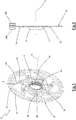
- reference numeral 10 wholly indicates a bicycle brake disc in accordance with the present invention.
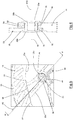
- the brake disc 10 is configured to be mounted on a hub (not illustrated) of a wheel of the bicycle between brake pads 100 (schematized in figure 2 ) of a brake caliper.
- the brake disc 10 rotates freely about a rotation axis X inside the space defined between the opposite brake pads 100 and by actuating a brake lever (not illustrated), the brake pads 100 are brought towards the brake disc 10, generating friction on the brake disc 10 and, consequently, braking the wheel.
- the brake disc 10 can be coupled with the hub of the wheel in per se known ways, for example through a central hole 11 having a grooved surface 12 matching a grooved surface of the hub (like in the embodiment illustrated in the attached figures) or through screws or bolts that axially and rotationally constrain the brake disc 10 to the hub.
- the brake disc 10 comprises a rotor 13 and a carrier 14.
- the carrier 14 is the portion of brake disc intended to be rotationally constrained to the hub of the wheel and the rotor 13 is the portion of brake disc intended to contact the brake pads 100.
- the carrier 14 is preferably made of aluminum or aluminum alloys, whereas the rotor 13 is preferably made of steel.
- the rotor 13 comprises a braking track 15 arranged in radially outer position and configured to rotate between the brake pads 100.
- the braking track 15 has a substantially annular extension, and can have an annular shape (like in the example illustrated in the attached drawings) or an undulating or multi-lobed shape to make a so-called daisy-wheel braking track.
- an annular shape like in the example illustrated in the attached drawings
- an undulating or multi-lobed shape to make a so-called daisy-wheel braking track.
- in the braking track 15 there can be a braking circumference 16 (illustrated in figure 2 ) having a diameter such as to intercept the brake pads 100.
- a plurality of through slits 17 of elongated shape can be provided that have the purpose of dissipating part of the heat generated on the braking track 15 during braking.
- the rotor 13 comprises a plurality of coupling seats 18 that are arranged radially towards the inside of the braking track 15 and that have the function of connecting the rotor 13 to the carrier 14.
- the coupling seats 18 are preferably made in one piece with the braking track 15.
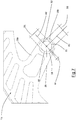
- Each coupling seat 18 is formed at an end of a coupling arm 18a that extends radially inwards from the braking track 16.
- the coupling arms 18a can have one or more weight-reduction through openings 19 (like in the embodiment illustrated in the attached figures).
- Each coupling arm 18a is circumferentially delimited by a first outer edge 20 and a second outer edge 21 between which one or more of the aforementioned weight-reduction through openings 19 can be provided.
- the first 20 and the second outer edge 21 can be parallel to one another or, more preferably not parallel, and can have a rectilinear or curved extension or one given by rectilinear and curved parts.
- the coupling arms 18a comprise a first 22 and a second circumferential end connection point 23 to the braking track 15.
- the first 22 and the second circumferential end point 23 are arranged in radially outer positions of the coupling arms 18a.
- the two end points 22, 23 are defined by the points circumferentially most distant from one another in which the coupling arm 18a connects to the braking track 15.
- the end points 22, 23 are defined by the intersection of an ideal circumference passing through the radially inner edge 15a of the braking track 15 and the coupling arm 18a.
- the carrier 14 comprises a plurality of coupling seats 24 to receive the coupling seats 18 of the rotor 13 and define connection areas 25 between the rotor 13 and the carrier 14.
- connection areas 25 the coupling seats 18 of the rotor 13 axially overlap the coupling seats 24 of the carrier 14 and are in direct contact with them, so as to make a non-floating connection.
- Each coupling arm 18a is identified between a respective connection area 25 in which it is connected with a respective coupling seat 24 of the carrier 14 and the first 20 and the second outer edge 21.
- connection areas 25, the coupling seats 24 of the carrier 14 and the coupling seats 18 of the rotor 13 are seven in number equally circumferentially spaced apart.
- mechanical joints 26 are provided, preferably rivets.
- connection area 25 On at least one connection area 25, the constraint between a coupling seat 18 of the rotor 13 and the respective coupling seat 24 of the carrier 14 has a degree of translational freedom.
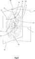
- Such a first reference axis A1 lies in a first reference plane P1 perpendicular to the rotation axis X of the brake disc 10 ( figure 8 ). It should be noted that the first reference plane P1 coincides with, or is parallel to, the lying plane of the braking track 15.
- connection area 25 furthermore, the constraint between a coupling seat 18 of the rotor 13 and the coupling seat 24 of the carrier 14 has a degree of rotational freedom with respect to a rotation axis AR1 parallel to the rotation axis of the brake disc 10.
- the first reference axis A1 passes through the connection area 25 and intersects a reference segment SR that passes through the first 22 and the second circumferential end point 23, as illustrated in figure 8 .
- the first reference axis A1, at the connection area 25, is comprised between the first 20 and the second outer edge 21 of the coupling arm 18a.
- the first reference axis A1 forms an angle AN comprised in absolute value between 0 and 80° with respect to a second reference plane P2 perpendicular to the first reference plane P1 and containing the rotation axis X.
- Such an angle AN is measured in a radially outer direction, as indicated in figure 8 .
- the angle AN is comprised, in absolute value, between 0 and 60°.
- the first reference axis A1 is comprised between the first 20 and the second outer edge 21 of the coupling arm 18a for the entire radial extension of the coupling arm 18a.
- connection area 25 In the preferred embodiment of the invention, what has been described above in relation to a connection area 25 is valid for all of the connection areas 25.
- connection areas 25 the constraint between a coupling seat 18 of the rotor 13 and the respective coupling seat 24 of the carrier 14 has a degree of translational freedom with respect to a respective reference axis A1.
- all of the reference axes A1 lie on the same first reference plane P1 and at least two of the reference axes A1 are not parallel to one another.
- connection area 25 The degree of translational freedom in each connection area 25 allows a mutual displacement of the coupling seat 18 of the rotor 13 with respect to the respective coupling seat 24 of the carrier 14 along the respective first reference axis A1.
- the coupling arms 18a can be shaped so that there are not two first reference axes A1 perfectly perpendicular to one another.
- the rotor 13 can move rigidly along the first reference plane P1 with respect to the carrier 14.
- the coupling arms 18a can alternatively be shaped so that there are at least two first reference axes A1 perfectly perpendicular to each other.
- the rotor 13 cannot move rigidly with respect to the carrier 14, since the rigid movement of the rotor 13 along the first of the two first reference axes would be impeded by the constraint to translation given by the second first reference axis perpendicular to the first of the two first reference axes.
- each coupling arm 18a has a thickness, measured in the axial direction, that is constant and preferably equal to the thickness of the braking track 15.
- the carrier 14 has a thickness in the axial direction that, preferably, is maximum at the groove 12 of the central hole and that decreases at the coupling seats 24, as indicated in figure 2 .
- each coupling seat 24 is formed on a radially outer portion 27 of the carrier 14.
- the radially outer portion 27 has a thickness in the axial direction reduced by an amount preferably equal to the thickness of the coupling seat 18 of the rotor 13.
- a shoulder 28 delimits, in the radially inner direction, the radially outer portion 27.
- the shape of the shoulder 28, in the preferred embodiment of the invention, is arched.
- the radially outer portion 27 is configured to receive in axial abutment the coupling seat 18 of the rotor 13, in particular an end portion 18b of the rotor 13 on which the coupling seat 18 is formed.
- the coupling seat 18, and in particular the end portion 18a does not contact the shoulder 28 of the radially outer portion 27.
- the end portion 18b is spaced from the shoulder 28 by a predetermined amount.
- the coupling seat 24 of the carrier has, or is defined by, a through hole 29 having a hole axis AF and passing through the geometric center of the hole itself.
- the hole axis AF coincides with the rotation axis AR1 with respect to which the coupling seat 18 of the rotor 13 and the coupling seat 24 of the carrier 14 have a degree of rotational freedom (as shown in figure 8 ).
- the through hole 29 is configured to receive the rivet 26.
- the through hole 29 has a first dimension D1 measured along the first reference axis A1 and a second dimension D2 measured along the second reference axis A2, which is contained in the first reference plane, is perpendicular to the first reference axis A1 and intersects the hole axis AF.
- the first reference axis A1 also intersects the hole axis AF.
- hole axis AF further coincides with the intersection point AF1 between the first reference axis A1 and the second reference axis A2.
- the second dimension D2 is substantially equal to the dimension of the stem 26a of the rivet 26 (already caulked) along the second reference axis A2.
- the first dimension D1 is greater than the second dimension D2.
- the first dimension D1 is at least 1.5% greater than the second dimension D2.
- the first dimension D1 is at least 3% greater than the second dimension D2.
- the first dimension D1 is less than 120% of the second dimension D2.
- the first dimension is about 105% of the second dimension D2.
- a brake disc having diameter of 160 millimeters has a through hole in which the second dimension D2 is 6.05 millimeters and the first dimension D1 is 6.35 millimeters.
- the through hole 29 preferably has a regular shape.
- the through hole 29 has (see figure 4 ) a first edge 30 and a second edge 31 of semi-circular shape, symmetrical to one another with respect to the second reference axis A2.
- the first 30 and the second edge 31 are joined together by two joining edges 32, symmetrical to one another with respect to the first reference axis A1.
- the two joining edges 32 preferably have an arched extension to make a substantially elliptical through hole 29.
- extension B1 measured along the first reference axis A1 of the two joining edges 32 defines the difference between the first D1 and the second dimension D2.
- the first dimension D1 coincides with the larger axis and the second dimension D2 coincides with the smaller axis of the elliptical shape of the through hole 29.
- the stem 26a of the rivet 26 does not contact all of the edges 30, 31, 32 of the through hole 29.
- the rivet 26 does not contact the entire extension of the first 30 and of the second edge 31.
- the coupling seat 18 of the rotor 13 has, or is defined by, a joining hole 32, preferably circular or in any case within a circumference.
- the diameter of the joining hole 32 ( figure 6 ) or of the circumference in the joining hole 32 is substantially equal to the diameter of the stem 26a of the rivet 26 when caulked.
- the rivet 26 is inserted both in the joining hole 32 and in the through hole 29 and, once caulked, has two opposite heads 26b that respectively act as axial shoulders for the coupling seat 18 of the rotor 13 and for the coupling seat 24 of the carrier 14, avoiding possible reciprocal translations of the rotor 13 with respect to the carrier 14 in the axial direction.
- the coupling seat 18 of the rotor 13 does not comprise the quoted joining hole 32 and comprises, or is defined by, a through hole 29 having the same features as the through hole 29 already described above.
- the coupling seat 24 of the carrier 14 can also comprise (or be defined by) a through hole 29 or a joining hole 32 (of the type described above).
- brake disc In an experimental test a comparison was made between two brake discs of the non-floating type, identical in dimensions, number of coupling seats and connection arms, materials and thicknesses and different only in that one brake disc does not have any constraint with a degree of translational freedom between coupling seat of the rotor and coupling seat of the carrier (hereinafter called conventional brake disc) and the other brake disc comprises a constraint with a degree of translational freedom (in accordance with the above) between all of the coupling seats of the rotor and all of the coupling seats of the carrier (hereinafter called brake disc in accordance with the invention).
- each brake disc was set in rotation about its own rotation axis and was suddenly braked with the same braking power (the rotation speed and the stopping time of the two brake discs being the same).
- An axial position transducer (a sensing lever) was arranged on each braking track to measure the axial shift of the braking track with respect to the starting axial position.
- the experimental test highlighted that during braking, in the conventional brake disc the braking track highlighted oscillations around the undeformed axial position of greater size (about 0.7 millimeters) with respect to the oscillations of the brake disc in accordance with the invention (about 0.1 millimeters).
- the frequency of oscillation was substantially the same for both brake discs.
- the conventional brake disc took about 45 seconds to recover its undeformed condition, whereas the brake disc in accordance with the invention took about 3 seconds to recover its undeformed condition.
Landscapes
- Engineering & Computer Science (AREA)
- General Engineering & Computer Science (AREA)
- Mechanical Engineering (AREA)
- Braking Arrangements (AREA)
Applications Claiming Priority (1)
| Application Number | Priority Date | Filing Date | Title |
|---|---|---|---|
| IT102017000092546A IT201700092546A1 (it) | 2017-08-09 | 2017-08-09 | Disco freno per bicicletta |
Publications (2)
| Publication Number | Publication Date |
|---|---|
| EP3441295A1 EP3441295A1 (en) | 2019-02-13 |
| EP3441295B1 true EP3441295B1 (en) | 2021-02-24 |
Family
ID=60766062
Family Applications (1)
| Application Number | Title | Priority Date | Filing Date |
|---|---|---|---|
| EP18186720.1A Active EP3441295B1 (en) | 2017-08-09 | 2018-07-31 | Bicycle brake disc |
Country Status (6)
| Country | Link |
|---|---|
| US (1) | US20190048950A1 (ja) |
| EP (1) | EP3441295B1 (ja) |
| JP (1) | JP2019049350A (ja) |
| CN (1) | CN109386560A (ja) |
| IT (1) | IT201700092546A1 (ja) |
| TW (1) | TWI763896B (ja) |
Families Citing this family (2)
| Publication number | Priority date | Publication date | Assignee | Title |
|---|---|---|---|---|
| TWI722937B (zh) * | 2020-07-02 | 2021-03-21 | 許再勝 | 浮動碟之鉚釘組 |
| TWI722936B (zh) * | 2020-07-02 | 2021-03-21 | 許再勝 | 浮動碟之內碟 |
Family Cites Families (23)
| Publication number | Priority date | Publication date | Assignee | Title |
|---|---|---|---|---|
| JPS61104842U (ja) * | 1984-12-14 | 1986-07-03 | ||
| JPH0249394Y2 (ja) * | 1987-05-21 | 1990-12-26 | ||
| US6135248A (en) * | 1995-11-08 | 2000-10-24 | Hayes Brake, Inc. | Brake disk |
| JP2916888B2 (ja) * | 1995-12-14 | 1999-07-05 | 株式会社ユタカ技研 | フローティングブレーキディスク |
| US6357561B2 (en) * | 1999-10-15 | 2002-03-19 | Stop Technologies Llc | Thermal expansion bushing in a metal matrix composite rotor |
| TW484551U (en) * | 2000-10-02 | 2002-04-21 | Robert J Seymour | Disk brake device |
| WO2004088162A1 (en) * | 2003-03-28 | 2004-10-14 | Hayes Disc Brakes, Llc | Quick-mount disc brake rotor |
| ES2354890T3 (es) * | 2004-05-18 | 2011-03-18 | Yutaka Giken Co., Ltd. | Freno de disco de tipo flotante. |
| WO2005111457A1 (ja) * | 2004-05-18 | 2005-11-24 | Yutaka Giken Co., Ltd. | フローティング型ディスクブレーキ |
| JP2006029552A (ja) * | 2004-07-21 | 2006-02-02 | Shimano Inc | 自転車用ディスクロータ |
| CN2889875Y (zh) * | 2005-12-07 | 2007-04-18 | 永祺车业股份有限公司 | 自行车花鼓碟盘锁固结构 |
| TWM335443U (en) * | 2008-01-30 | 2008-07-01 | yi-zhen Zhang | Brake disc device |
| US8353391B2 (en) * | 2008-07-08 | 2013-01-15 | Yutaka Giken Co., Ltd. | Floating type brake disc |
| ES2366889T3 (es) * | 2008-08-29 | 2011-10-26 | Stanislav Spacek | Disco de freno flotante. |
| ES2465943B1 (es) * | 2012-12-07 | 2014-12-05 | Marcos PÉREZ FERRER | Conjunto de freno de disco para un vehículo con un soporte interior y un aro exterior dividido en una pluralidad de sectores |
| JP5783994B2 (ja) * | 2012-12-25 | 2015-09-24 | 本田技研工業株式会社 | 車輪速センサーリング取り付け構造 |
| TWM462809U (zh) * | 2013-04-11 | 2013-10-01 | Talonbrake Industry Co Ltd | 自行車可替換浮動式碟盤 |
| DE202013104350U1 (de) * | 2013-09-24 | 2013-10-09 | Kun-Liang Chieh | Aufbau einer Schwimmscheibenbremse |
| CN104976253A (zh) * | 2014-04-11 | 2015-10-14 | 曾玉娟 | 浮动碟盘组合装置 |
| CN104309753B (zh) * | 2014-10-16 | 2017-02-08 | 宏展五金塑胶制品(苏州)有限公司 | 一种自行车制动盘 |
| TWM505425U (zh) * | 2015-02-12 | 2015-07-21 | Min-Lang Zeng | 浮動式煞車盤 |
| ITUB20155214A1 (it) * | 2015-10-19 | 2017-04-19 | Grimeca S R L | Disco freno. |
| US9874256B2 (en) * | 2016-01-07 | 2018-01-23 | Hb Performance Systems, Inc. | Brake rotor with tilted mounting slots |
-
2017
- 2017-08-09 IT IT102017000092546A patent/IT201700092546A1/it unknown
-
2018
- 2018-07-31 EP EP18186720.1A patent/EP3441295B1/en active Active
- 2018-08-02 TW TW107126808A patent/TWI763896B/zh active
- 2018-08-07 JP JP2018148081A patent/JP2019049350A/ja active Pending
- 2018-08-08 US US16/058,208 patent/US20190048950A1/en not_active Abandoned
- 2018-08-09 CN CN201810901609.4A patent/CN109386560A/zh active Pending
Non-Patent Citations (1)
| Title |
|---|
| None * |
Also Published As
| Publication number | Publication date |
|---|---|
| TWI763896B (zh) | 2022-05-11 |
| IT201700092546A1 (it) | 2019-02-09 |
| JP2019049350A (ja) | 2019-03-28 |
| EP3441295A1 (en) | 2019-02-13 |
| TW201910656A (zh) | 2019-03-16 |
| US20190048950A1 (en) | 2019-02-14 |
| CN109386560A (zh) | 2019-02-26 |
Similar Documents
| Publication | Publication Date | Title |
|---|---|---|
| EP3441295B1 (en) | Bicycle brake disc | |
| US9249848B2 (en) | Motor vehicle brake disc | |
| JP5224207B2 (ja) | 扇形片に分割された制動ディスクを備えた車輪用ブレーキ | |
| US4630713A (en) | Disc brake with sliding caliper | |
| JP2008540967A (ja) | ブレーキディスク・ハブ結合構造 | |
| US9897152B2 (en) | Wear optimized pad design | |
| TWI652189B (zh) | 碟式煞車碟盤及音輪 | |
| US5560452A (en) | Reinforcement device for carbon brake disks, and a brake disk fitted with such devices | |
| EP3910210B1 (en) | Brake rotor | |
| JP5349000B2 (ja) | タービンエンジンホイール | |
| WO2007041490A1 (en) | Aircraft wheel assembly | |
| CN113494552A (zh) | 刹车盘 | |
| SE463113B (sv) | Friktionsdyna | |
| US6135248A (en) | Brake disk | |
| EP3899306A1 (en) | Assembly of at least two brake pads and at least one spring | |
| JPH0227531B2 (ja) | ||
| US3456768A (en) | Disc element construction for disc brake | |
| CN109790890B (zh) | 车轮制动装置 | |
| ES2873798T3 (es) | Freno de disco rotor flotante con el accesorio de anillo expansor Marcel | |
| WO2004025133A1 (en) | Support for sliding brake discs | |
| US5884741A (en) | Friction clutch for a motor vehicle with wear adjustment | |
| US4120536A (en) | Wheel equipped with brake, particularly for motor-cycles | |
| JP2010530510A (ja) | 膨張部材を備えるシャフトハブ組立体 | |
| JP5140152B2 (ja) | 軸受カップに支持されるコンベヤーローラ | |
| US5803813A (en) | Tripod roller for a constant velocity universal joint |
Legal Events
| Date | Code | Title | Description |
|---|---|---|---|
| PUAI | Public reference made under article 153(3) epc to a published international application that has entered the european phase |
Free format text: ORIGINAL CODE: 0009012 |
|
| STAA | Information on the status of an ep patent application or granted ep patent |
Free format text: STATUS: THE APPLICATION HAS BEEN PUBLISHED |
|
| AK | Designated contracting states |
Kind code of ref document: A1 Designated state(s): AL AT BE BG CH CY CZ DE DK EE ES FI FR GB GR HR HU IE IS IT LI LT LU LV MC MK MT NL NO PL PT RO RS SE SI SK SM TR |
|
| AX | Request for extension of the european patent |
Extension state: BA ME |
|
| STAA | Information on the status of an ep patent application or granted ep patent |
Free format text: STATUS: REQUEST FOR EXAMINATION WAS MADE |
|
| 17P | Request for examination filed |
Effective date: 20190730 |
|
| RBV | Designated contracting states (corrected) |
Designated state(s): AL AT BE BG CH CY CZ DE DK EE ES FI FR GB GR HR HU IE IS IT LI LT LU LV MC MK MT NL NO PL PT RO RS SE SI SK SM TR |
|
| STAA | Information on the status of an ep patent application or granted ep patent |
Free format text: STATUS: EXAMINATION IS IN PROGRESS |
|
| 17Q | First examination report despatched |
Effective date: 20191121 |
|
| GRAP | Despatch of communication of intention to grant a patent |
Free format text: ORIGINAL CODE: EPIDOSNIGR1 |
|
| STAA | Information on the status of an ep patent application or granted ep patent |
Free format text: STATUS: GRANT OF PATENT IS INTENDED |
|
| INTG | Intention to grant announced |
Effective date: 20201028 |
|
| GRAS | Grant fee paid |
Free format text: ORIGINAL CODE: EPIDOSNIGR3 |
|
| GRAA | (expected) grant |
Free format text: ORIGINAL CODE: 0009210 |
|
| STAA | Information on the status of an ep patent application or granted ep patent |
Free format text: STATUS: THE PATENT HAS BEEN GRANTED |
|
| AK | Designated contracting states |
Kind code of ref document: B1 Designated state(s): AL AT BE BG CH CY CZ DE DK EE ES FI FR GB GR HR HU IE IS IT LI LT LU LV MC MK MT NL NO PL PT RO RS SE SI SK SM TR |
|
| REG | Reference to a national code |
Ref country code: CH Ref legal event code: EP |
|
| REG | Reference to a national code |
Ref country code: AT Ref legal event code: REF Ref document number: 1364128 Country of ref document: AT Kind code of ref document: T Effective date: 20210315 |
|
| REG | Reference to a national code |
Ref country code: IE Ref legal event code: FG4D |
|
| REG | Reference to a national code |
Ref country code: DE Ref legal event code: R096 Ref document number: 602018012932 Country of ref document: DE |
|
| REG | Reference to a national code |
Ref country code: LT Ref legal event code: MG9D |
|
| REG | Reference to a national code |
Ref country code: NL Ref legal event code: MP Effective date: 20210224 |
|
| PG25 | Lapsed in a contracting state [announced via postgrant information from national office to epo] |
Ref country code: BG Free format text: LAPSE BECAUSE OF FAILURE TO SUBMIT A TRANSLATION OF THE DESCRIPTION OR TO PAY THE FEE WITHIN THE PRESCRIBED TIME-LIMIT Effective date: 20210524 Ref country code: GR Free format text: LAPSE BECAUSE OF FAILURE TO SUBMIT A TRANSLATION OF THE DESCRIPTION OR TO PAY THE FEE WITHIN THE PRESCRIBED TIME-LIMIT Effective date: 20210525 Ref country code: HR Free format text: LAPSE BECAUSE OF FAILURE TO SUBMIT A TRANSLATION OF THE DESCRIPTION OR TO PAY THE FEE WITHIN THE PRESCRIBED TIME-LIMIT Effective date: 20210224 Ref country code: FI Free format text: LAPSE BECAUSE OF FAILURE TO SUBMIT A TRANSLATION OF THE DESCRIPTION OR TO PAY THE FEE WITHIN THE PRESCRIBED TIME-LIMIT Effective date: 20210224 Ref country code: NO Free format text: LAPSE BECAUSE OF FAILURE TO SUBMIT A TRANSLATION OF THE DESCRIPTION OR TO PAY THE FEE WITHIN THE PRESCRIBED TIME-LIMIT Effective date: 20210524 Ref country code: PT Free format text: LAPSE BECAUSE OF FAILURE TO SUBMIT A TRANSLATION OF THE DESCRIPTION OR TO PAY THE FEE WITHIN THE PRESCRIBED TIME-LIMIT Effective date: 20210624 Ref country code: LT Free format text: LAPSE BECAUSE OF FAILURE TO SUBMIT A TRANSLATION OF THE DESCRIPTION OR TO PAY THE FEE WITHIN THE PRESCRIBED TIME-LIMIT Effective date: 20210224 |
|
| REG | Reference to a national code |
Ref country code: AT Ref legal event code: MK05 Ref document number: 1364128 Country of ref document: AT Kind code of ref document: T Effective date: 20210224 |
|
| PG25 | Lapsed in a contracting state [announced via postgrant information from national office to epo] |
Ref country code: LV Free format text: LAPSE BECAUSE OF FAILURE TO SUBMIT A TRANSLATION OF THE DESCRIPTION OR TO PAY THE FEE WITHIN THE PRESCRIBED TIME-LIMIT Effective date: 20210224 Ref country code: NL Free format text: LAPSE BECAUSE OF FAILURE TO SUBMIT A TRANSLATION OF THE DESCRIPTION OR TO PAY THE FEE WITHIN THE PRESCRIBED TIME-LIMIT Effective date: 20210224 Ref country code: PL Free format text: LAPSE BECAUSE OF FAILURE TO SUBMIT A TRANSLATION OF THE DESCRIPTION OR TO PAY THE FEE WITHIN THE PRESCRIBED TIME-LIMIT Effective date: 20210224 Ref country code: RS Free format text: LAPSE BECAUSE OF FAILURE TO SUBMIT A TRANSLATION OF THE DESCRIPTION OR TO PAY THE FEE WITHIN THE PRESCRIBED TIME-LIMIT Effective date: 20210224 Ref country code: SE Free format text: LAPSE BECAUSE OF FAILURE TO SUBMIT A TRANSLATION OF THE DESCRIPTION OR TO PAY THE FEE WITHIN THE PRESCRIBED TIME-LIMIT Effective date: 20210224 |
|
| PG25 | Lapsed in a contracting state [announced via postgrant information from national office to epo] |
Ref country code: IS Free format text: LAPSE BECAUSE OF FAILURE TO SUBMIT A TRANSLATION OF THE DESCRIPTION OR TO PAY THE FEE WITHIN THE PRESCRIBED TIME-LIMIT Effective date: 20210624 |
|
| PG25 | Lapsed in a contracting state [announced via postgrant information from national office to epo] |
Ref country code: EE Free format text: LAPSE BECAUSE OF FAILURE TO SUBMIT A TRANSLATION OF THE DESCRIPTION OR TO PAY THE FEE WITHIN THE PRESCRIBED TIME-LIMIT Effective date: 20210224 Ref country code: CZ Free format text: LAPSE BECAUSE OF FAILURE TO SUBMIT A TRANSLATION OF THE DESCRIPTION OR TO PAY THE FEE WITHIN THE PRESCRIBED TIME-LIMIT Effective date: 20210224 Ref country code: SM Free format text: LAPSE BECAUSE OF FAILURE TO SUBMIT A TRANSLATION OF THE DESCRIPTION OR TO PAY THE FEE WITHIN THE PRESCRIBED TIME-LIMIT Effective date: 20210224 Ref country code: AT Free format text: LAPSE BECAUSE OF FAILURE TO SUBMIT A TRANSLATION OF THE DESCRIPTION OR TO PAY THE FEE WITHIN THE PRESCRIBED TIME-LIMIT Effective date: 20210224 |
|
| REG | Reference to a national code |
Ref country code: DE Ref legal event code: R097 Ref document number: 602018012932 Country of ref document: DE |
|
| PG25 | Lapsed in a contracting state [announced via postgrant information from national office to epo] |
Ref country code: RO Free format text: LAPSE BECAUSE OF FAILURE TO SUBMIT A TRANSLATION OF THE DESCRIPTION OR TO PAY THE FEE WITHIN THE PRESCRIBED TIME-LIMIT Effective date: 20210224 Ref country code: DK Free format text: LAPSE BECAUSE OF FAILURE TO SUBMIT A TRANSLATION OF THE DESCRIPTION OR TO PAY THE FEE WITHIN THE PRESCRIBED TIME-LIMIT Effective date: 20210224 Ref country code: SK Free format text: LAPSE BECAUSE OF FAILURE TO SUBMIT A TRANSLATION OF THE DESCRIPTION OR TO PAY THE FEE WITHIN THE PRESCRIBED TIME-LIMIT Effective date: 20210224 |
|
| PLBE | No opposition filed within time limit |
Free format text: ORIGINAL CODE: 0009261 |
|
| STAA | Information on the status of an ep patent application or granted ep patent |
Free format text: STATUS: NO OPPOSITION FILED WITHIN TIME LIMIT |
|
| PG25 | Lapsed in a contracting state [announced via postgrant information from national office to epo] |
Ref country code: AL Free format text: LAPSE BECAUSE OF FAILURE TO SUBMIT A TRANSLATION OF THE DESCRIPTION OR TO PAY THE FEE WITHIN THE PRESCRIBED TIME-LIMIT Effective date: 20210224 Ref country code: ES Free format text: LAPSE BECAUSE OF FAILURE TO SUBMIT A TRANSLATION OF THE DESCRIPTION OR TO PAY THE FEE WITHIN THE PRESCRIBED TIME-LIMIT Effective date: 20210224 |
|
| 26N | No opposition filed |
Effective date: 20211125 |
|
| PG25 | Lapsed in a contracting state [announced via postgrant information from national office to epo] |
Ref country code: SI Free format text: LAPSE BECAUSE OF FAILURE TO SUBMIT A TRANSLATION OF THE DESCRIPTION OR TO PAY THE FEE WITHIN THE PRESCRIBED TIME-LIMIT Effective date: 20210224 |
|
| REG | Reference to a national code |
Ref country code: CH Ref legal event code: PL |
|
| PG25 | Lapsed in a contracting state [announced via postgrant information from national office to epo] |
Ref country code: MC Free format text: LAPSE BECAUSE OF FAILURE TO SUBMIT A TRANSLATION OF THE DESCRIPTION OR TO PAY THE FEE WITHIN THE PRESCRIBED TIME-LIMIT Effective date: 20210224 |
|
| REG | Reference to a national code |
Ref country code: BE Ref legal event code: MM Effective date: 20210731 |
|
| PG25 | Lapsed in a contracting state [announced via postgrant information from national office to epo] |
Ref country code: LI Free format text: LAPSE BECAUSE OF NON-PAYMENT OF DUE FEES Effective date: 20210731 Ref country code: CH Free format text: LAPSE BECAUSE OF NON-PAYMENT OF DUE FEES Effective date: 20210731 |
|
| PG25 | Lapsed in a contracting state [announced via postgrant information from national office to epo] |
Ref country code: IS Free format text: LAPSE BECAUSE OF FAILURE TO SUBMIT A TRANSLATION OF THE DESCRIPTION OR TO PAY THE FEE WITHIN THE PRESCRIBED TIME-LIMIT Effective date: 20210624 Ref country code: LU Free format text: LAPSE BECAUSE OF NON-PAYMENT OF DUE FEES Effective date: 20210731 |
|
| PG25 | Lapsed in a contracting state [announced via postgrant information from national office to epo] |
Ref country code: IE Free format text: LAPSE BECAUSE OF NON-PAYMENT OF DUE FEES Effective date: 20210731 Ref country code: BE Free format text: LAPSE BECAUSE OF NON-PAYMENT OF DUE FEES Effective date: 20210731 |
|
| GBPC | Gb: european patent ceased through non-payment of renewal fee |
Effective date: 20220731 |
|
| PG25 | Lapsed in a contracting state [announced via postgrant information from national office to epo] |
Ref country code: GB Free format text: LAPSE BECAUSE OF NON-PAYMENT OF DUE FEES Effective date: 20220731 |
|
| P01 | Opt-out of the competence of the unified patent court (upc) registered |
Effective date: 20230517 |
|
| PG25 | Lapsed in a contracting state [announced via postgrant information from national office to epo] |
Ref country code: CY Free format text: LAPSE BECAUSE OF FAILURE TO SUBMIT A TRANSLATION OF THE DESCRIPTION OR TO PAY THE FEE WITHIN THE PRESCRIBED TIME-LIMIT Effective date: 20210224 |
|
| PG25 | Lapsed in a contracting state [announced via postgrant information from national office to epo] |
Ref country code: HU Free format text: LAPSE BECAUSE OF FAILURE TO SUBMIT A TRANSLATION OF THE DESCRIPTION OR TO PAY THE FEE WITHIN THE PRESCRIBED TIME-LIMIT; INVALID AB INITIO Effective date: 20180731 |
|
| PGFP | Annual fee paid to national office [announced via postgrant information from national office to epo] |
Ref country code: IT Payment date: 20230720 Year of fee payment: 6 |
|
| PGFP | Annual fee paid to national office [announced via postgrant information from national office to epo] |
Ref country code: FR Payment date: 20230725 Year of fee payment: 6 Ref country code: DE Payment date: 20230727 Year of fee payment: 6 |
|
| PG25 | Lapsed in a contracting state [announced via postgrant information from national office to epo] |
Ref country code: MK Free format text: LAPSE BECAUSE OF FAILURE TO SUBMIT A TRANSLATION OF THE DESCRIPTION OR TO PAY THE FEE WITHIN THE PRESCRIBED TIME-LIMIT Effective date: 20210224 |