EP3439460B1 - Système intelligent d'arrosage - Google Patents
Système intelligent d'arrosage Download PDFInfo
- Publication number
- EP3439460B1 EP3439460B1 EP16716528.1A EP16716528A EP3439460B1 EP 3439460 B1 EP3439460 B1 EP 3439460B1 EP 16716528 A EP16716528 A EP 16716528A EP 3439460 B1 EP3439460 B1 EP 3439460B1
- Authority
- EP
- European Patent Office
- Prior art keywords
- watering
- mode
- watering pump
- pump
- user
- Prior art date
- Legal status (The legal status is an assumption and is not a legal conclusion. Google has not performed a legal analysis and makes no representation as to the accuracy of the status listed.)
- Active
Links
- XLYOFNOQVPJJNP-UHFFFAOYSA-N water Substances O XLYOFNOQVPJJNP-UHFFFAOYSA-N 0.000 claims description 70
- 238000012545 processing Methods 0.000 claims description 44
- 238000004891 communication Methods 0.000 claims description 28
- 238000012423 maintenance Methods 0.000 claims description 20
- 230000004044 response Effects 0.000 claims description 14
- 238000001514 detection method Methods 0.000 claims description 5
- 230000001419 dependent effect Effects 0.000 claims description 4
- 241001061260 Emmelichthys struhsakeri Species 0.000 description 27
- 230000000875 corresponding effect Effects 0.000 description 15
- 238000010586 diagram Methods 0.000 description 8
- 230000000694 effects Effects 0.000 description 8
- 230000006870 function Effects 0.000 description 7
- 238000003973 irrigation Methods 0.000 description 7
- 230000002262 irrigation Effects 0.000 description 7
- 238000007726 management method Methods 0.000 description 7
- 238000000034 method Methods 0.000 description 7
- 239000002689 soil Substances 0.000 description 7
- 230000007246 mechanism Effects 0.000 description 6
- 241000196324 Embryophyta Species 0.000 description 5
- 230000003044 adaptive effect Effects 0.000 description 5
- 230000003993 interaction Effects 0.000 description 5
- 230000008859 change Effects 0.000 description 4
- 238000010413 gardening Methods 0.000 description 4
- 238000012544 monitoring process Methods 0.000 description 4
- 238000005406 washing Methods 0.000 description 4
- 244000025254 Cannabis sativa Species 0.000 description 3
- 230000009471 action Effects 0.000 description 3
- 230000005540 biological transmission Effects 0.000 description 3
- 230000001276 controlling effect Effects 0.000 description 3
- 238000003780 insertion Methods 0.000 description 3
- 230000037431 insertion Effects 0.000 description 3
- 230000000007 visual effect Effects 0.000 description 3
- 238000004364 calculation method Methods 0.000 description 2
- 239000003795 chemical substances by application Substances 0.000 description 2
- 238000005520 cutting process Methods 0.000 description 2
- 230000007613 environmental effect Effects 0.000 description 2
- 230000008014 freezing Effects 0.000 description 2
- 238000007710 freezing Methods 0.000 description 2
- 230000006872 improvement Effects 0.000 description 2
- 238000005259 measurement Methods 0.000 description 2
- 230000004048 modification Effects 0.000 description 2
- 238000012986 modification Methods 0.000 description 2
- 238000005507 spraying Methods 0.000 description 2
- 238000013519 translation Methods 0.000 description 2
- 230000002159 abnormal effect Effects 0.000 description 1
- 230000004913 activation Effects 0.000 description 1
- 230000002776 aggregation Effects 0.000 description 1
- 238000004220 aggregation Methods 0.000 description 1
- 230000003796 beauty Effects 0.000 description 1
- 230000006399 behavior Effects 0.000 description 1
- 239000003086 colorant Substances 0.000 description 1
- 230000002596 correlated effect Effects 0.000 description 1
- 230000008878 coupling Effects 0.000 description 1
- 238000010168 coupling process Methods 0.000 description 1
- 238000005859 coupling reaction Methods 0.000 description 1
- 238000013500 data storage Methods 0.000 description 1
- 230000003111 delayed effect Effects 0.000 description 1
- 230000001066 destructive effect Effects 0.000 description 1
- 239000006185 dispersion Substances 0.000 description 1
- 230000003370 grooming effect Effects 0.000 description 1
- 230000002452 interceptive effect Effects 0.000 description 1
- 230000007257 malfunction Effects 0.000 description 1
- 239000000463 material Substances 0.000 description 1
- 230000005012 migration Effects 0.000 description 1
- 238000013508 migration Methods 0.000 description 1
- 238000012806 monitoring device Methods 0.000 description 1
- 238000003825 pressing Methods 0.000 description 1
- 230000008569 process Effects 0.000 description 1
- 238000002791 soaking Methods 0.000 description 1
- 239000007787 solid Substances 0.000 description 1
- 238000003860 storage Methods 0.000 description 1
- 239000000126 substance Substances 0.000 description 1
- 230000002123 temporal effect Effects 0.000 description 1
- 230000001960 triggered effect Effects 0.000 description 1
Images


Classifications
-
- A—HUMAN NECESSITIES
- A01—AGRICULTURE; FORESTRY; ANIMAL HUSBANDRY; HUNTING; TRAPPING; FISHING
- A01G—HORTICULTURE; CULTIVATION OF VEGETABLES, FLOWERS, RICE, FRUIT, VINES, HOPS OR SEAWEED; FORESTRY; WATERING
- A01G25/00—Watering gardens, fields, sports grounds or the like
- A01G25/02—Watering arrangements located above the soil which make use of perforated pipe-lines or pipe-lines with dispensing fittings, e.g. for drip irrigation
-
- A—HUMAN NECESSITIES
- A01—AGRICULTURE; FORESTRY; ANIMAL HUSBANDRY; HUNTING; TRAPPING; FISHING
- A01G—HORTICULTURE; CULTIVATION OF VEGETABLES, FLOWERS, RICE, FRUIT, VINES, HOPS OR SEAWEED; FORESTRY; WATERING
- A01G25/00—Watering gardens, fields, sports grounds or the like
- A01G25/16—Control of watering
- A01G25/167—Control by humidity of the soil itself or of devices simulating soil or of the atmosphere; Soil humidity sensors
-
- A—HUMAN NECESSITIES
- A01—AGRICULTURE; FORESTRY; ANIMAL HUSBANDRY; HUNTING; TRAPPING; FISHING
- A01G—HORTICULTURE; CULTIVATION OF VEGETABLES, FLOWERS, RICE, FRUIT, VINES, HOPS OR SEAWEED; FORESTRY; WATERING
- A01G25/00—Watering gardens, fields, sports grounds or the like
- A01G25/16—Control of watering
- A01G25/165—Cyclic operations, timing systems, timing valves, impulse operations
-
- G—PHYSICS
- G05—CONTROLLING; REGULATING
- G05B—CONTROL OR REGULATING SYSTEMS IN GENERAL; FUNCTIONAL ELEMENTS OF SUCH SYSTEMS; MONITORING OR TESTING ARRANGEMENTS FOR SUCH SYSTEMS OR ELEMENTS
- G05B2219/00—Program-control systems
- G05B2219/20—Pc systems
- G05B2219/26—Pc applications
- G05B2219/2625—Sprinkler, irrigation, watering
Definitions
- Example embodiments generally relate to intelligent systems and, more particularly, relate to a system for intelligent watering that includes components configured to facilitate easy interface and operation.
- Grounds care maintenance tasks may include lawn care and/or gardening tasks related to facilitating growth and manicuring the lawns or gardens that hopefully prosper as a result of those efforts.
- Facilitating growth has commonly required individuals to focus routine attention on ensuring growing conditions are appropriate for the vegetation being grown, and on providing the necessary care and grooming tasks to further enhance growth.
- WO 2009/049361 A1 describes a water resource management system that employs several sensors as well as a watering pump disposed on a parcel of land and being part of a communication network that allows distant control via a common user terminal. The watering pump operates via an operation mode in accordance to the command of the user terminal.
- the programmable logic controller of the automated irrigation system with US 2014/236868 A1 will automatically force a reconnection of the deployed devices by a reset of power so that these devices can recontinue to operate.
- Some example embodiments may therefore provide a capability for intelligent control or management of a number of assets in connection with yard maintenance with the assistance or inclusion of a user terminal.
- sensor equipment and watering equipment operation may be coordinated remotely for efficient gardening and lawn care using a smart watering pump.
- the system according to claim 1 includes sensor equipment including one or more sensors disposed on a parcel of land, watering equipment disposed on the parcel and configured to selectively apply water to the parcel, and a gateway configured to provide for communication with the sensor equipment and the watering equipment.
- the watering equipment according to claim 1 includes a watering pump operably coupled to a water source and a water line to alternately couple the water source to and isolate the water source from the water line, and processing circuitry.
- the processing circuitry is configured to determine an operational mode of the watering pump; and direct the watering pump to operate in accordance with the operational mode.
- a watering pump for intelligent control or management of yard maintenance is provided in claim 15.
- Some example embodiments may improve the ability of operators to maximize the beauty and productivity of their yards and gardens, but do so in a user friendly and intuitive way.
- operable coupling should be understood to relate to direct or indirect connection that, in either case, enables functional interconnection of components that are operably coupled to each other.
- Example embodiments may provide an intelligent system for monitoring and/or maintaining yard conditions (i.e., lawn and/or garden conditions) at any of what may potentially be a number of locations throughout a particular parcel, and allowing the operator to interface with devices within the system in a flexible way.
- the devices of the system may be coordinated in their activities and/or may be configured to adapt to their environment or at least to the current conditions or stimuli that are present in their environment.
- the operations conducted and/or monitoring may be accomplished with the assistance of a mobile asset such as a robotic rover.
- the system may utilize a communication network that gathers information on growing conditions from sensor equipment for association of the information with the areas from which the information was gathered.
- the system may also employ an interface mechanism that allows the operator to have a great deal of flexibility with remotely controlling various components of the system and programming such components via processing circuitry at each respective component. Programming may therefore be coordinated remotely, but at least some of the programming may also be stored locally so that the system can operate with or without connectivity.
- the connectivity aspects of the system may utilize home network components and wide area network components (e.g., the internet), but may also include a gateway that is configured to interface between the deployed components (e.g., components in the yard/garden or otherwise related to yard maintenance) and the home network/wide area network components.
- the processing aspects may be distributed between local and remote management components so that some aspects of yard maintenance may utilize remote assets or at least incorporate information available from abroad, while other aspects can be managed locally.
- adaptability and ease of interface and control are characteristics of the system that are improved by employing example embodiments.
- the system may therefore employ any combination of fixed and/or mobile assets that gather data that relates to specific segments of the parcel that may correspond to respective different areas.
- the system may employ an intelligent watering pump that is configured to be programmed for servicing one or more such specific segments.
- the specific segments may have different types of plants therein, and therefore may optimally have different growing conditions desirable in connection with each respective one of the segments.
- the owner/operator may program operating instructions to guide the deployed components (including the intelligent watering pump) relative to operations in one or more of the specific segments, which may be referred to as "zones."
- the processing circuitry may be equipped to allow the user to define specific operating parameters and the system may then adapt to the current conditions to operate according to the operating parameters.
- the system may be employed to correlate desirable growing conditions to an identified plant species based on stored information associated with each plant species from a database or online resource.
- each zone may have corresponding growing condition parameters associated therewith, and the user can see the growing condition parameters relative to the various areas and program operation of system components accordingly relative to maintaining desired growing conditions (e.g., any or all of moisture level, temperature, lighting level, pH, and/or the like) for the corresponding zone.
- desired growing conditions e.g., any or all of moisture level, temperature, lighting level, pH, and/or the like
- schedules among deployed components may be deconflicted or otherwise organized to prevent damage to components, ineffective use of resources, or efficiency reducing behaviors.
- the deployed components associated with the zones may provide the operator with reports and/or warnings via the gateway to enable the operator to intercede in certain situations, or the components may simply respond and inform the operator of their responses via the gateway.
- FIG. 1 illustrates a block diagram of a system 10 that may be employed to accomplish the basic operations described above in accordance with the invention.
- certain tasks like grass cutting, chemical application, visual monitoring and/or the like may be performed by a robot or robotic rover 15. Because the system could operate without the robotic rover 15, the robotic rover 15 is shown in dashed lines in FIG. 1 . Robots or other devices could also be engaged to perform certain other yard maintenance tasks such as raking, fertilizing, lighting, wildlife dispersion and/or the like.
- sprinkler/irrigation heads and/or a watering pump that interfaces therewith.
- the sprinkler/irrigation heads may be attached to hoses and the watering pump may provide a mechanism by which to control the turning on/off of water application at the respective sprinkler/irrigation head locations by providing a central intelligently controllable source for providing water to the sprinkler/irrigation heads and/or the hoses.
- the hoses, sprinkler/irrigation heads, and/or watering pump may together form watering equipment 20.
- various sensors may be employed by insertion of such sensors into soil for monitoring soil or other growing conditions (e.g., lighting levels, moisture levels, pH, temperature, video or image data, etc.). These sensors may therefore be understood to take various forms within the system 10. However, generally speaking, the sensors may have connectivity to the system 10 in order to enhance operation of system components on the basis of the soil and/or growing condition information gathered by the sensors. Regardless of the specific configuration or placement paradigm, the various sensors may represent sensor equipment 30, as described above.
- the sensor equipment 30, and in some cases also one or more of the devices that comprise the watering equipment 20, may be in communication with a gateway 40 via wired or wireless connections.
- the gateway 40 may subsequently have wired or wireless connection to an access point (AP) 45, which may be directly or indirectly connectable to a user terminal 50.
- the AP 45 may be a router of a home network of the operator.
- direct connection of the AP 45 to the user terminal 50 may be provided via short range wireless communication methods (e.g., Bluetooth, WiFi and/or the like). Indirect connection of the AP 45 to the user terminal 50 may occur via a network 60.
- the network 60 may be a data network, such as a local area network (LAN), a metropolitan area network (MAN), a wide area network (WAN) (e.g., the internet), a wireless personal area network (WPAN), and/or the like, which may couple devices (e.g., the deployed components) to devices such as processing elements (e.g., personal computers, server computers or the like) and/or databases such as the user terminal 50.
- LAN local area network
- MAN metropolitan area network
- WAN wide area network
- WPAN wireless personal area network
- Communication between the network 60 and other devices of the system 10 may be accomplished by either wireline or wireless communication mechanisms and corresponding communication protocols.
- some or all of the sensors of the sensor equipment 30, the watering equipment 20 and/or the robotic rover 15 may be connected to the user terminal 50 by wire and/or be wireless communication means.
- the robotic rover 15 may act as one or both of a piece of sensor equipment 30 or a piece of watering equipment 20. However, given the ability of the robotic rover 15 to act as either or both of a piece of sensor equipment 30 or a piece of watering equipment 20 and the ability of the robotic rover 15 to perform other tasks (e.g., grass cutting) in combination with or independent of the sensor equipment 30 and the watering equipment 20, the robotic rover 15 is shown separately in FIG. 1 .
- the gateway 40 may be a translation agent configured to interface with any or all of the deployed components via wired or wireless communication.
- the gateway 40 may include a high performance antenna to enable the gateway 40 to communicate wirelessly with deployed components via an 868 mHz radio link (e.g., a first wireless link).
- 868 mHz radio link e.g., a first wireless link
- the first wireless link, and the components connected thereby may be part of a first network (e.g., a garden network) or deployed component network that extends outdoors. Components internal to the house or business, and extending to and between the user terminal 50 may form a second network.
- the gateway 40 may be a translation agent between the first and second networks.
- the gateway 40 may be an aggregation point and communications center for communications in both networks.
- the gateway 40 may be provided within the home or otherwise indoor environment of the operator, and still wirelessly communicate with the deployed components (via the first wireless link) to translate instructions thereto from the operator, which may be provided via a second wireless link to the AP 45.
- the wireless communications may be secured by employing encryption or other security techniques.
- the gateway 40 may also provide secure cloud data storage through connection to the network 60 (e.g., via the AP 45).
- the first and second wireless links may be different wireless links that employ different communication protocols and/or frequencies.
- the gateway 40 may also provide the ability for each of the deployed components to be monitored, controlled, programmed, or otherwise interfaced with by an operator using the user terminal 50.
- the user terminal 50 may be configured to execute an application (or app) that is tailored to providing an easy setup and/or easy to use interface for interaction with the gateway 40 (and the corresponding deployed components that are reachable through the gateway 40).
- the user terminal 50 may therefore be a smartphone or other mobile terminal, or a laptop, PC, or other computing/communication device.
- the user terminal 50 may include processing circuitry that is enabled to interface with corresponding processing circuitry of the gateway 40 and/or the deployed components to program, control or otherwise interact with the deployed components in a manner described in greater detail below.
- the interaction between the user terminal 50 and the gateway 40 to facilitate programming of, control of, or interaction with the deployed components may create an interactive and fully connectable garden system for irrigation or mowing control/coordination.
- the app that may be executed at the user terminal 50 may be configured for control of any or all of the deployed components on a real time or programmed basis.
- the resulting system may be a holistic and connected automatic garden system.
- the connection to content on the internet via network 60 may allow educational content to be integrated into the system's operation to provide operators with an improved interface and more control over gaining full satisfaction of their gardening experience.
- the educational content may include videos that example how to start, program, or troubleshoot any operations regarding the components of the water equipment 20.
- the app may be used to program at least some of the watering equipment 20 to operate on a locally stored watering schedule in a first mode and operate as an autonomous pressure pump in a second mode of operation.
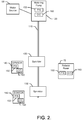
- FIG. 2 illustrates a water migration path that may be practiced in connection with an example embodiment.
- some of the components may be removed in simpler example embodiments, and some components may be added to provide more complex architectures in other example embodiments.
- the example of FIG. 2 is not provided to be limiting in relation to the components included in the system limited by the appended claims.
- FIG. 2 shows a single water delivery line, other embodiments can employ multiple water delivery lines to service a parcel or yard.
- example embodiments may be practiced with any number of lines, and with separate and/or different water sources.
- a water source 100 may be used to charge a water line 110 via a watering pump 120.
- the water source 100 may also charge a second water line via a second watering pump, or via the first watering pump 120.
- the water line 110 may be a flexible water hose or garden hose.
- the watering pump 120 may be one of the deployed components that forms one component of the watering equipment 20 of FIG. 1 .
- the watering pump 120 may be operably coupled to the water source 100 such that the water source 100 is a pressurized water supply for the water line 110 when the watering pump 120 is operational.
- the water line 110 may be substantially depressurized, or at least only have residual pressure remaining from the last operation of the watering pump 120.
- the water source 100 is not a typical pressurized water supply of a house or other structure. Instead, the water source 100 may typically be an otherwise unpressurized water source, such as a reservoir or cistern.
- one or more sprinklers may receive water from the water line 110.
- the water line 110 may be selectively charged under control of the watering pump 120 to provide water for spraying from the first and second sprinklers 130 and 132.
- the second water line may be selectively charged under control of the watering pump 120, or a second watering pump, to provide water for spraying from any additional sprinklers associated with the second water line.
- the first and second sprinklers 130 may be provided with pressurized water that is distributed therethough responsive to operation of the watering pump 120.
- the first and second sprinklers 130 and 132 may typically be components that are not provided with any local intelligence.
- first and second sprinklers 130 and 132 may only be controllable via operation of the watering pump 120 to turn on and off watering functions.
- first and second sprinklers 130 and 132 could have intelligent components and/or control aspects provided therein in some cases.
- One or more sensors may also be provided at various locations in the parcel that is served by the sprinklers to detect or sense conditions proximate to the corresponding sensors.
- the first and second sensors 140 and 142 may each correspond to a respective one of the first and second sprinklers 130 and 132, and the app at the user terminal 50 may be configured to note such correspondence so that information received from a respective one of the first or second sensor 140 or 142 can be correlated to actions that may be ordered to the watering pump 120, if needed, based on the information.
- some of the deployed components may include a power supply (P/S) 150 that is local to the corresponding ones of the deployed components.
- the P/S 150 of each component may be a battery or battery pack, or mains power.
- Each powered one of the deployed components may also include communication circuitry (C/C) 160 that includes processing circuitry for controlling each respective component and an antenna for enabling the deployed components to communicate with the gateway 40 via the first wireless link (or alternatively via a wired connection).
- the robotic rover 15 (if employed) may also be an example of the deployed components, and thus the robotic rover 15 may also include the P/S 150 and the C/C 160.
- the various power supply and communication circuitry components may have different scale, structure and configuration features.
- the watering pump 120 operates under the control of the C/C 160 to respectively isolate and operably couple the water source 100 from/to the water line 110.
- the watering pump 120 operates based on operational and volume mode instructions received through the gateway 40 or based on operational and volume information stored or otherwise accessible via the C/C 160 of the watering pump 120.
- the watering pump 120 may provide convenience to operation of the system 10 since the watering pump 120 can be controlled from anywhere and/or at anytime via the app at the user terminal 50, or via locally stored programming instructions, by selecting or executing the desired/programmed operational and volume mode, as described in greater detail below.
- the C/C 160 may include processing circuitry 201, as shown in FIG. 3 .
- the processing circuitry 201 that may be configured to perform data processing, control function execution, and/or other processing and management services according to the present invention.
- the processing circuitry 201 may be embodied as a chip or chip set.
- the processing circuitry 201 may comprise one or more physical packages (e.g., chips) including materials, components and/or wires on a structural assembly (e.g., a baseboard).
- the structural assembly may provide physical strength, conservation of size, and/or limitation of electrical interaction for component circuitry included thereon.
- the processing circuitry 201 may therefore, in some cases, be configured to implement an embodiment of the present invention on a single chip or as a single "system on a chip.” As such, in some cases, a chip or chipset may constitute means for performing one or more operations for providing the functionalities described herein.
- the processing circuitry 201 may include one or more instances of a processor 205 and memory 203 that may be in communication with or otherwise control a device interface 207.
- the processing circuitry 201 may be embodied as a circuit chip (e.g., an integrated circuit chip) configured (e.g., with hardware, software or a combination of hardware and software) to perform operations described herein.
- the processing circuitry 201 may communicate with internal electronic components of the watering pump 120, the first or second sensors 140 and 142 and/or the robotic rover 15, and enable communication externally with other components.
- the device interface 207 may include one or more interface mechanisms for enabling communication with other devices via the gateway 40.
- the device interface 207 may be any means such as a device or circuitry embodied in either hardware, or a combination of hardware and software that is configured to receive and/or transmit data from/to the gateway 40 by virtue of the device interface 207 being capable of sending and receiving messages via the gateway 40.
- the device interface 207 may provide interfaces for communication of components of or external to the system 10 via the gateway 40.
- the device interface 207 may further interface with a sensor (e.g., a temperature sensor, a pH sensor, a light sensor, a moisture sensor and/or the like) to obtain sensor data for communication to other devices (e.g., the watering pump(s)). Meanwhile, if the C/C 160 is for a watering pump, the device interface 207 may provide interfaces to other onboard components (e.g., a user interface including lights and a main button as described below).
- a sensor e.g., a temperature sensor, a pH sensor, a light sensor, a moisture sensor and/or the like
- other onboard components e.g., a user interface including lights and a main button as described below.
- the processor 205 may be embodied in a number of different ways.
- the processor 205 may be embodied as various processing means such as one or more of a microprocessor or other processing element, a coprocessor, a controller or various other computing or processing devices including integrated circuits such as, for example, an ASIC (application specific integrated circuit), an FPGA (field programmable gate array), or the like.
- the processor 205 may be configured to execute instructions stored in the memory 203 or otherwise accessible to the processor 205.
- the processor 205 may represent an entity (e.g., physically embodied in circuitry - in the form of processing circuitry 201) capable of performing operations according to embodiments of the present invention while configured accordingly.
- the processor 205 when the processor 205 is embodied as an ASIC, FPGA or the like, the processor 205 may be specifically configured hardware for conducting the operations described herein.
- the processor 205 when the processor 205 is embodied as an executor of software instructions, the instructions may specifically configure the processor 205 to perform the operations described herein.
- the processor 205 may be embodied as, include or otherwise control the C/C 160.
- the processor 205 may be said to cause each of the operations described in connection with the C/C 160 (and corresponding distributed component with which the C/C 160 is associated) by directing the C/C 160 to undertake the corresponding functionalities responsive to execution of instructions or algorithms configuring the processor 205 (or processing circuitry 201) accordingly.
- the C/C 160 of the sensors may be configured to detect environmental parameters (e.g., sensor data) and report the sensor data via the first wireless link to the gateway 40 (and ultimately to the app on the user terminal 50 or to storage in the cloud via the network 60) or to the watering pump 120.
- the C/C 160 of the sensors may be configured to determine a difference between a prior set of sensor data (e.g., the magnitude of a previous sensor measurement) and the current set of sensor data (e.g., the magnitude of a most recent sensor measurement). The amount of difference may then be used to determine whether or not the sensor will report the current set of sensor data. If the difference is small (e.g., less than a threshold amount) the sensor may not report the new value.
- the C/C 160 of the sensors may be configured to perform battery conservation techniques relative to reporting of sensor data.
- the C/C 160 of the sensors may also be configured to otherwise report (or make a determination on whether to report based on the criteria discussed above) sensor data on a given schedule or responsive to certain activities or events.
- a trigger event e.g., temporal or action based trigger
- the C/C 160 of the sensor may make a determination of the current sensor data and decide whether or not to report the sensor data.
- the C/C 160 of the watering pump 120 may be configured to receive instructions from the gateway 30 regarding an operational mode of the watering pump 120 as defined by the app, or by locally stored programming.
- the gateway 40 may receive instructions from the user via the user terminal 50 regarding what operational mode (e.g., controlling on/off cycles of the pump) the user desires the watering pump 120 to operate in.
- the user-selectable operational modes of the watering pump 120 may include, but are not limited to, an intelligent mode, a scheduled mode, or a manual mode.
- the intelligent mode is selected by the user, the watering pump 120 may operate independently based on programmed triggers. In some cases, the triggers may be sensor data received from the first or second sensor 140 or 142.
- the C/C 160 of the watering pump 120 may be programmed to turn on the watering pump 120 and provide water when sensor data falling within or exceeding certain ranges or thresholds is received.
- the watering pump 120 may be configured to energize the watering pump 120 to enable delivery of water to the sprinklers.
- the operator may select a schedule on which the watering pump 120 may operate. For example, the user may select certain times or days in which the watering pump 120 should operate. If the manual mode is selected by the user, the watering pump 120 may only operate upon the user selecting an option on the user terminal 50 that directs the operation of the watering pump 120. Therefore, the user at any time may decide to water the lawn and may direct the watering pump 120, via the user terminal 50, to operate. In some cases, the user may select more than one operational mode at a time. For example, the user may send instructions, via the gateway 40, to the watering pump 120 regarding a schedule on which the watering pump 120 is to operate.
- the user may instruct the watering pump 120 to also simultaneously act in the intelligent mode.
- the user may define triggers under which the watering pump 120 may operate. These triggers may include, but are not limited to, the soil moisture falling below or exceeding a given threshold.
- the watering pump 120 via the C/C 160, may be configured to operate on a schedule while also operating in response to pre-defined triggers. Even if the user has selected that the watering pump 120 is to operate under both the intelligent and scheduled mode, the user may select the manual operation mode which causes the watering pump 120 to operate whenever the user desires. The user may select this manual operation mode without affecting the already programmed intelligent and scheduled modes.
- the C/C 160 of the watering pump 120 may be configured to receive instructions from the user (via the gateway 40) regarding a volume mode of the watering pump 120. Therefore, the gateway 40 may receive instructions from the user via the user terminal 50 regarding not only what operational mode (e.g., on/off cycle control) the user desires the watering pump 120 to operate in, but what volume mode the watering pump 120 should operate in where the volume mode defines pump speed or output pressure.
- the volume modes of the watering pump 120 that may be selectable by the user include, but are not limited to, 1) micro drip mode; 2) small amount mode; 3) conservation mode; 4) automatic mode; or 5) garden mode.
- the micro drip mode for example, may supply a small amount of water at a gentle drip or trickle pressure.
- the user may select the micro drip mode for irrigating or watering flowers or vegetation.
- the small amount mode may be suitable for when only a small area is being irrigating or watered.
- the conservation mode may ensure that the watering pump 120 is not operational while a shower, washing machine, dish washer, or the like is being operated in the house associated with the parcel to ensure sufficient water pressure is maintained both in the home and at the watering pump 120.
- the automatic mode may allow the C/C 160 of the watering pump 120 to determine the appropriate volume of water to be supplied by the watering pump 120 based on the on sensor data received from the first or second sensor 140 or 142.
- the garden mode may be selected when a full soaking of the garden, lawn, or flower bed is desired and full pump or line pressure is desired.
- the volume modes may be selectable based on certain areas of the lawn or parcel. Even further, some of the volume modes may be selectable simultaneously. For example, the user, via the user terminal 50, may select that the garden mode should be employed on Saturday at 8:00 a.m. for zone 1 of the parcel. In conjunction with selecting the garden mode for the applicable time period for zone 1, the user may also select the conservation mode. Therefore, if the washing machine is running at 8:00 a.m. on Saturday morning, the C/C 160 may be configured to delay the operation of the watering pump 120 in garden mode until there is detection that the washing machine has shut-off or until a preset time delay expires.
- the user may be alerted, via the user terminal 50, that the garden mode was not implemented due the detection of the washing machine being operated. Upon receiving this alert, the user may override the conservation mode and implement the garden mode, or in some cases, the user may select when the garden mode should be rescheduled.
- the last received instructions regarding the operational or volume mode from the user may be stored locally in the memory 203 of the C/C 160. Accordingly, if the C/C 160 loses connectivity to the gateway 40, the C/C 160 may continue to employ the last received instructions regarding the operational or volume mode of the watering pump 120. If the C/C 160 loses connectivity to the gateway 40 or loses connectivity for longer than a predetermined time period, the C/C 160 may be configured to override the last received instructions from the user regarding the selected operational or volume mode and switch to a default setting. In some cases, the default setting may the intelligent operational mode or the automatic volume mode.
- the C/C 160 will determine the appropriate time to water and the appropriate volume of water to be supplied by the watering pump 120 based on sensor data received from the first or second sensor 140 or 142. In either case, the default settings or the last received instructions (and any programs associated therewith) are stored locally at the C/C 160 so that the watering pump 120 can operate independently of connectivity to the network 60.
- the C/C 160 of the robotic rover 15 may be configured to control the travels and operations of the robotic rover 15. Moreover, the C/C 160 of the robotic rover 15 may allow the gateway 40 to grant user access to modification of the schedule of operations of the robotic rover 15 and/or to take real-time control over various operations of the robotic rover 15. In an example embodiment, the app at the user terminal 50 may be employed to coordinate and/or de-conflict programmed water schedules and mowing schedules.
- the app at the user terminal 50 may provide alerts to indicate that the proposed changes to the schedule or current operational mode may be problematic, or may prevent the making of such changes.
- the robotic rover 15 is mowing in an area in which a sensor indicates a low soil moisture value that would normally trigger operation of the watering pump 120 via the programming of the watering pump 120, an alert may be provided to indicate that the robotic rover 15 should have its operations changed, or the opening of the watering pump 120 may be delayed.
- the electronic deployed components may further include a local operator 211 (e.g., a button, knob or other control device) provided at a portion thereof.
- the local operator 211 may be provided to allow local manual setting of one or more characteristics of the watering pump 120.
- the local operator 211 may be used to determine pump output pressure, speed, volume mode, operational mode, and/or the like.
- the local operator 211 may trigger different functionalities through the programming of the processing circuitry 201 for corresponding different situations and/or actuation methods. For example, some actuation of the local operator 211 may cause the corresponding device to go into a pairing mode.
- the device may be detectable by the gateway 40 and/or other devices for a given period of time.
- the app on the user terminal 50 may be used to detect the device in pairing mode and, once detected, the app may also be used to pair the device to another device (e.g., of the first network - the deployed component network).
- the gateway 40 and the C/C 160 of the corresponding devices may then be capable of communication with each other on a continuous, event driven, or scheduled basis via the first wireless link.
- the first sensor 140 may be configured to provide sensor data to the watering pump 120 (e.g., via the gateway 40).
- the first sensor 140 may be paired with the watering pump 120 via a setup procedure and communicate thereafter on a schedule or an activity/event driven basis.
- simple replacement or insertion of a battery to power up the device may be an additional or alternative method by which to initiate the pairing mode.
- certain defined actuation (or patterns of actuation) of the local operator 211 may result in returning the device to factory settings. As such, contents of the memory 203 may be cleared or otherwise reset to initial settings or conditions. Other functions may also or alternatively be provided. Moreover, some devices may have additional buttons or operable members.
- Communication between the gateway 40 and the sensors or watering pumps may occur for pairing purposes and to facilitate the operational activities for which the system 10 is ultimately configured.
- the operator may use the app at the user terminal 50 to connect to the gateway 40 and may be provided with one or more control console or interface screens that provide options for interacting with deployed components and/or for programming the deployed components, as described above.
- initial setup of the system may be facilitated by placing individual deployed components (either sequentially or simultaneously) in a pairing mode.
- the deployed components are then discoverable via the first wireless link and can be added to the first network. Once added to the first network, the deployed components are considered to be assets of the first network that can be interacted with/programmed and/or the like.
- the deployed components can then be paired with each other and configured for individual and/or cooperative functional performance.
- the watering pump 120 may be paired with other second watering pumps, with the robotic rover 15 and/or the first sensor 140.
- the operator may have options provided (e.g., via the app) to select the desired operational or volume mode of the watering pump 120.
- the watering pump 120 may therefore be instructed regarding the specific stimuli that may be received from the first sensor 140 to trigger operation of the watering pump 120.
- the watering pump 120 may be provided with (e.g., in the memory 203) a schedule or a trigger which causes the watering pump 120 to "ping" or otherwise reach out to the first sensor 140 to initiate communication to receive sensor data. Based on the sensor data received (e.g., if certain threshold parameters are reached or not), the watering pump 120 may be opened or closed.
- the watering pump 120 When the watering pump 120 is paired with and connected to the robotic rover 15, automatic coordination of schedules may be accomplished at least relative to ensuring that mowing and watering are not conducted in the same area at the same time.
- the app on the user terminal 50 may ensure that scheduling of mowing during watering (or vice versa) is not possible. However, given that the operator can take control of the watering pumps and/or the robotic rover 15 to initiate operations, the app on the user terminal 50 may further prevent any attempts to initiate operations of watering pumps or the robotic rover 15 in real-time when the other is also operating in the same area.
- watering schedules or operations can be coordinated to manage or prevent under-pressure situations or excessive draining of the water source 100.
- the watering pumps are connected to the same water source, it may be possible for water supply to be insufficient to effectively charge both the water line 110 and the second water line at the same time.
- operations of one may be communicated to the other (e.g., via the gateway 40) so that the water source 100 and its supply of water can be managed effectively.
- the deployed components of various example embodiments may be adaptive to various conditions or situations.
- the adaptive nature of the deployed components may be provided, as described above, as a programmable feature, where the operator can use the user terminal 50 to program modes, adjustable parameters, relationships, or responses.
- the programmable features should be understood to be remotely programmable (i.e., programmable from the app and/or the user terminal 50 remote from the component being programmed) via the gateway 40.
- the adaptive nature of the deployed components may be provided as a default feature.
- the adaptive capabilities of the deployed components may either be dependent upon connectivity (e.g., connectivity dependent) for remote programming, or may be connectivity independent (e.g., default programming that exists or is instituted when there is no connectivity or responsive to a loss of connectivity.
- battery power levels may be communicated to the gateway 40 and signal strength values relating to communication with the sensors and/or watering pumps may also be determined at the gateway 40.
- This information (along with sensor data) may be provided to the app at the user terminal 50 to alert the operator when battery power is low, or signal strengths are low. Battery replacement and/or sensor repositioning may then be undertaken to improve the situation.
- the sensor may also adaptively respond to its surroundings to trigger reports.
- the watering pump 120 may attempt to ping the first sensor 140 via the gateway 40 to trigger a report of sensor data.
- the first sensor 140 may be configured (e.g., via the C/C 160) to determine the amount of change in the requested parameter before deciding whether to respond to the ping.
- a change of at least a specific amount or percentage e.g., 5% may be required before the first sensor 140 will report sensor data via wireless transmission. Since wireless transmission consumes more power than internal operation (e.g., to determine the amount of change and current sensor data), by saving several transmission cycles when there is little data change, battery life can be substantially extended.
- the last value received may be substituted and communicated to the operator (e.g., via the app).
- the operator can turn on/off or wake up the watering pumps and/or sensors by sending instructions via the user terminal 50 through the gateway 40.
- the wake up message may be used to see if the devices are still reacting and active, or to request specific data from or initiate actions at such components in real time.
- the operator can send a wakeup, or setup signal to have the corresponding device beacon for at least a predetermined amount of time (e.g., three minutes).
- the devices may be positioned and the operator may check the app to see what signal strength is detected by the gateway 40. The operator can therefore position the devices in real time and make sure that the position in which a device is currently located is a good location from the perspective of its ability to communicate with the gateway 40.
- one or more of the deployed components may further include frost warning capability.
- frost warning capability since the watering pumps typically may have some residual water therein, it should be appreciated that freezing of water in the body of the watering pumps may be destructive to the watering pumps. Accordingly, the C/C 160 of one or more components (especially the watering pumps) may be configured to identify situations where there is a potential for frost that may damage the watering pumps or other watering equipment 20. In some embodiments, if the temperature reaches a predetermined threshold distance from the freezing point (e.g., 5 degrees C, or 10 degrees F), an alert may be issued (e.g., through the app at the user terminal 50) to warn the operator that the watering pump 120 (and/or sensors) should be brought in to avoid damage.
- a predetermined threshold distance from the freezing point e.g., 5 degrees C, or 10 degrees F
- the predetermined threshold may be a factory setting, or may be set by the operator. However, in either case, the ability to identify a present temperature condition to alert the operator of a possible frost event is another example of how the deployed components may be configured (by operator program or by default) to be adaptive relative to their surroundings and/or circumstances.
- the adaptability of the deployed components relates to the inability to connect to the first network or a loss of connection to the first network.
- the last received operation or volume mode could be maintained in the cloud, on the user terminal 50, or elsewhere, in some cases, the current operational or volume mode (or at least a portion thereof) may be stored locally at the watering pumps.
- the memory 203 may be configured to record at least the last water schedule information employed.
- the watering pump 120 may store at least the information indicative of its last watering schedule.
- the watering pump 120 operated at 1300 and shut down at 1305, if no connection to the network 60 for determining the watering schedule can be achieved, or if connectivity is lost, the watering pump 120 will continue to water on the previously provided operational and volume mode.
- the C/C 160 of the watering pump 120 determines that connectivity has been lost for longer than a pre-determined time interval, the C/C 160 may be configured to override the previously provided operational and volume mode to operate on the default setting, as described above.
- C/C 160 of the deployed components may able to determine the usage and runtime of each of the deployed components.
- the C/C 160 may be configured to monitor and calculate the runtime of and the water usage by the watering pump 120. Therefore, the C/C 160 may be able to determine the volume of water used over a specific time interval, such as an hour, day, week, month, or plurality of months (i.e., seasons). These calculations may be provided to the user via the user terminal 50. Based on the calculations, the C/C 160 may determine an average runtime and usage of the watering pump 120 over a pre-determined time interval. Using these calculated average runtime and usage values, the C/C 160 may be configured to monitor any further usage and runtime of the watering pump 120. If the runtime or usage exceeds the average runtime and usage values, the C/C 160 may be configured to send an alert, via the gateway 40, to the user terminal 50 to indicate the status detection of the abnormal condition.
- An even further example of the adaptability of the deployed components relates to the ability of the C/C of the deployed components to determine the recommended maintenance interval for the deployed components.
- the C/C 160 of the watering pump 120 may be able to calculate a recommended maintenance interval of the watering pump 120. This recommended maintenance interval may be displayed on the user terminal 50.
- the user may be able to override this recommended maintenance interval.
- the user may be able to select how he or she wants to calculate the maintenance interval (i.e., after a certain time period or certain calculated usage amount).
- the C/C 160 may be configured to alert the user when the time period has passed or when the specified usage amount occurs. Even further, the user may be able to input when the last maintenance was performed on the watering pump 120. By inputting the last maintenance performed, the C/C 160 may be configured reset the maintenance interval and recalculate in accordance with the above.
- the C/C 160 of the deployed components may be even further configured to send messages to the user that operation of the deployed component has started.
- the C/C 160 may be configured to send messages if the deployed component fails during operation or if an error occurs during operation. If a failure or error occurs during the operation of the deployed component, the user terminal 50 may have an option to for the user to send feedback to the manufacturer or supplier of the error or failure.
- the user terminal 50 may be configured to allow the manufacturer or supplier to have remote access of the deployable component in response to receiving a request from a user or in response to receiving feedback regarding the failure or error of the deployable component.
- the watering pump 120 described above could take different physical forms.
- an example structure for embodying a watering pump 120 may be a reciprocating or rotary pump.
- the watering pump 120 may include a centrifugal pump having an impeller.
- other pump structures can also be employed.
- the deployed components may be largely controlled by the user via the user terminal 50.
- the user terminal 50 could be a mobile device (e.g., a smartphone) or a fixed terminal (e.g., a PC).
- the user terminal 50 could also be other devices such as a tablet, laptop and/or the like.
- the user terminal 50 may be configured to provide a simple and intuitive interface for enabling the operator to control operation of the system 10.
- FIG. 4 illustrates a block diagram of some components of the user terminal 50 that may configure the user terminal to provide the app for control of the system 10.
- the user terminal 50 may include processing circuitry 310, a processor 312, memory 314 and device interface 320 that may be similar in form and/or function to the processing circuitry 201, processor 205, memory 203 and device interface 207 described above. Specific structures, forms and scales of such components may differ. However, the general capabilities may be similar so these components will not be described in detail again in detail. Instead, it should be appreciated that except for changes in specific configuration, content and structure, these components are generally similar. As shown in FIG. 4 , the user terminal 50 may further include a user interface 330 and an operation manager 340.
- the user interface 330 may be in communication with the processing circuitry 310 to receive an indication of a user input at the user interface 330 and/or to provide an audible, visual, mechanical or other output to the user.
- the user interface 330 may include, for example, a display (e.g., a touch screen display), one or more buttons or keys (e.g., function buttons or a keyboard), and/or other input/output mechanisms (e.g., microphone, mouse, speakers, cursor, joystick, lights and/or the like).
- the user interface 330 may be configured to provide alerts, warnings and/or notifications to the user or operator responsive to various trigger conditions being detected (e.g., via the sensor equipment 30 or other components).
- System malfunctions, damage or tampering with equipment, equipment theft and other component related stimuli may also be defined as triggers for generation of the alerts, warnings and/or notifications.
- the user interface 330 may be configured to generate such alerts, warnings and/or notifications in response to the runtime or usage of the watering pump 120 being out of the recommended ranges, or in response to system components having schedule or operational conflicts. Notifications may also be provided regarding general status, current conditions and/or the like.
- the alerts, warnings and/or notifications may be generated via light, sound, visual display, or other devices that may be connected to or part of the operation manager 340. In some cases, the notifications may be provided by text message or email.
- the user interface 330 may be configured to enable the user to delegate operation of the system to second user for a predetermined period of time. For example, if the user is going on vacation or will be out of town, the second user may be given permission to control the system via the second user's user interface.
- the processing circuitry 310 may be configured to perform data processing, control function execution and/or other processing and management services according to an example embodiment of the present invention.
- the processing circuitry 310 may be configured to control or be embodied as the operation manager 340.
- the operation manager 340 may be configured to receive sensor information from the sensor equipment 30 and/or the watering equipment 20 and make decisions regarding information to be provided to the owner/operator and/or instructions to be provided to the sensor equipment 30 and/or the watering equipment 20.
- the processing circuitry 310 may, in some cases, process the condition information received from the sensor equipment 30 and compare the condition information to growing condition parameters that are stored in the memory 314 for a given zone.
- the memory 314 may be configured to store information, data, applications, instructions or the like for enabling the operation manager 340 to carry out various functions in accordance with exemplary embodiments of the present invention.
- the memory 314 could be configured to buffer input data for processing by the processor 312.
- the memory 314 could be configured to store instructions for execution by the processor 312.
- the memory 314 may include one or more databases that may store a variety of data sets responsive to input from the sensor network.
- applications may be stored for execution by the processor 312 in order to carry out the functionality associated with each respective application.
- the applications may include applications for generation of control consoles for providing options for control of the system.
- the applications may also or alternatively include applications for receiving information regarding component activity/status, environmental parameters, operational or volume mode, device pairing, and/or the like to allow the operation manager 340 to define responses to the information (e.g., based on predefined programming or user input).
- the information/parameters may be entered by the operator, received from deployed components, or may be extracted or retrieved from databases or sources accessible via the internet based on entry of an identity of the plant vegetation in a given zone.
- the operation manager 340 may therefore, for example, provide interface mechanisms for control of the operation of the watering pumps.
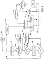
- FIG. 5 illustrates a block diagram of one example of operations that may be facilitated by the operation manager 340 in accordance with an example embodiment.
- the watering pump may initially be off, but the user terminal 50 may present a control console (or series of control consoles) via which the operator can provide instructions to initiate the operations of FIG. 5 .
- An instruction may be provided at operation 400 to turn on the watering pump 120 (i.e., via selecting manual mode).
- a signal regarding the volume mode may be received at operation 401.
- an activation signal may be issued from the user terminal 50 to the watering pump 120 to direct operation thereof at operation 410.
- the watering pump 120 may then remain in an operating state until the time duration expires, at which time the watering pump 120 may turn off and flow returns to the initial state.
- the operator may also insert instructions to manually turn off the watering pump 120 at operation 412.
- a determination may then be made as to whether the manual turning off is before or overlaps with a scheduled start time at operation 414. If this manual turn off (off schedule) defines an end time that is before the scheduled next start time, the schedule may be maintained at operation 416 and the watering pump 120 may turn off at operation 420 so that flow may return to the initial state to be ready for operation again in accordance with the schedule.
- the schedule may be skipped at operation 418 and the watering pump 120 may turn off at operation 420 so that flow may return to the initial state to be ready for operation again when the next scheduled operating time arrives.
- the watering pump 120 may operate at operation 410 at the corresponding time, and responsive to time expiring at operation 424, the watering pump 120 may shut off.
- the watering pump 120 may operate at operation 410 and then shut off after a predetermined period of time expires at operation 424 or when the condition clears at operation 428.
- the operator may also manually operates or shuts off the watering pump 120 by operating a local button or knob at the watering pump 120. If manual (local) operation is performed, the operations described above may still be performed and the times for remaining opening (or a next programmed opening) may again be governed by the schedule information input into the operation manager 340.
- the watering pump 120 may include a limited user interface in the form of a main button (or knob) provided on a front panel thereof, and a light assembly.
- the light assembly may include three LEDs the LEDs may be capable of expressing red, green and yellow colors in a solid or flashing manner. The LEDs may be useful for providing status information associated with attempts to pair the watering pump with another device, battery status, pump status, and/or the like.
- the user interface 330 of the user terminal 50 may be employed initially to provide control console options for adding devices to the first network so that they are discovered by the gateway 40 and are recognized by the operation manager 340.
- the pairing mode e.g., by battery insertion into a deployed component, or by pressing the reset button, or by selection of an option on the user terminal 50
- the watering pump may be discovered by the gateway 40 and the gateway 40 may communicate the identity of the discovered watering pump to the user operation manager 340 so that information indicative of the discovered watering pump can be displayed at the user interface 330.
- a determination is then made as to whether pairing is possible.
- the user interface 330 of the user terminal 50 may also or alternatively provide an indication of detection of the watering pump.
- LED lighting output may be generated to indicate as much.
- the LED lighting outputs during the pairing mode may be converted to a signal strength indicator. Again similar indications could also be provided at the user terminal 50.
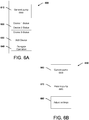
- FIG. 6 which includes FIGS. 6A-6C , illustrates some examples of interface screens or control consoles that may be provided by the operation manager 340 in some embodiments.
- FIG. 6A illustrates a basic start screen showing a home page 600 for the app.
- the app may display a general watering pump data section 610, which may display runtime and usage data associated with watering pump 120.
- the app may also display device status information 620, which may show each device of the first network along with corresponding status information such as, for example, battery status, operational modes, operational status, and/or the like.
- an option may also be provided for adding new devices in box 630.
- an option may be provided for delegated operation of the system to a second user in box 640, as described above.
- FIG. 6B illustrates an example pump status screen 650 that may be accessed responsive to selecting the watering pump data section 610.
- the pump status screen 650 may include a current pump data section 660 that may display current pump data.
- a historical pump data section 670 may also be provided to show past data over a given period of time (that may be user selectable).
- a settings adjustment option 680 may also be provided to allow the operator to select various pump settings.
- the pump settings may relate to selecting operational or volume modes, pairing activity, signal strength, battery levels, identifying plant types nearby, identifying soil type and/or the like.
- FIG. 6C illustrates an example device status screen 700 that may be accessed responsive to selecting the adjust settings section 680.
- the user may be able to select what zone of the parcel the user wishes to adjust the watering settings at section 710. Once the appropriate zone is selected, the user may be able to select the operational and volume modes that the watering pump 120 is to operate in at sections 720 and 730, respectively. For example, if the user selects intelligent mode in section 720, the user may then be prompted to select the appropriate volume mode from section 730. Even after selecting the intelligent operational mode in section 720, the user may then select either or both of the scheduled or manual modes in connection with the same zone if the user desires. At section 740, the user may select the reset button in order to clear all currently stored operational and volume mode settings.
Claims (15)
- Système (10) d'appareils comprenant :un équipement de détection (30) comprenant un ou plusieurs capteurs (140, 142), disposé sur une parcelle de terrain ;un équipement d'arrosage (20) disposé sur la parcelle et configuré pour appliquer de façon sélective de l'eau sur la parcelle ;un terminal utilisateur (50) ; etune passerelle (40) configurée pour communiquer avec l'équipement de détection (30), l'équipement d'arrosage (20) et le terminal utilisateur (50),dans lequel l'équipement d'arrosage (20) comprend une pompe d'arrosage (120), la pompe d'arrosage (120) étant couplée de façon opérationnelle à une source d'eau (100) et à une conduite d'eau (110) pour coupler par alternance la source d'eau (100) avec, et isoler la source d'eau (100) de la conduite d'eau (110), et la pompe d'arrosage (120) comprend un circuit de communication (160) comprenant un circuit de traitement (201) destiné à commander la pompe d'arrosage (120) et une antenne permettant à la pompe d'arrosage (120) de communiquer avec la passerelle (40),dans lequel le circuit de traitement (201) est configuré pour :déterminer un mode de fonctionnement de la pompe d'arrosage (120) ; etdiriger la pompe d'arrosage (120) pour fonctionner selon le mode de fonctionnement, caractérisé en ce quela pompe d'arrosage (120) comprend une mémoire (203) pour stocker localement les réglages par défaut ou les dernières instructions reçues,et le circuit de traitement (201) est en outre configuré pour détecter une perte de connectivité avec la passerelle (40) ou le capteur (140, 142),dans lequel le circuit de traitement (201) est en outre configuré pour déterminer, sur la base des premières instructions reçues de la passerelle (40), un mode de volume de la pompe d'arrosage (120),dans lequel, en réponse à la détection de la perte de connectivité, le circuit de traitement (201) utilise un mode de fonctionnement et un mode de volume déterminés en dernier lieu, ou remplace les dernières instructions reçues d'un utilisateur, concernant le mode de fonctionnement ou de volume sélectionné et passe à un réglage par défaut.
- Système (10) selon la revendication 1, dans lequel le passage à un réglage par défaut ne se produit que si la perte de connectivité dépasse un intervalle de temps prédéterminé.
- Système (10) selon la revendication 2, dans lequel le réglage par défaut est un mode de fonctionnement intelligent ou un mode de volume automatique.
- Système (10) selon l'une quelconque des revendications précédentes, dans lequel la passerelle (40) présente une interface entre un premier réseau comprenant au moins l'équipement d'arrosage (20) et l'équipement de détection (30) et un second réseau à travers lequel un premier utilisateur peut communiquer sans fil avec la passerelle (40) via le terminal utilisateur (50).
- Système selon (10) selon l'une quelconque des revendications précédentes, dans lequel le mode de fonctionnement de la pompe d'arrosage (120) comprend un parmi le mode intelligent, un mode programmé ou un mode manuel.
- Système (10) selon la revendication 5, dans lequel au mode intelligent, la pompe d'arrosage (120) fonctionne en réponse aux données de capteur reçues, incluses dans, ou dépassant une plage ou un seuil prédéfini.
- Système (10) selon la revendication 5 lorsqu'elle dépend de la revendication 4, dans lequel au mode programmé, la pompe d'arrosage (120) fonctionne en réponse à un programme d'arrosage programmé par le premier utilisateur.
- Système (10) selon la revendication 5, dans lequel le terminal utilisateur (50) comprend une interface (630) et, dans lequel au mode manuel, la pompe d'arrosage (120) fonctionne en réponse à une sélection d'utilisateur sur l'interface (630) qui dirige le fonctionnement immédiat de la pompe d'arrosage (120).
- Système (10) selon l'une quelconque des revendications précédentes, dans lequel le mode de volume de la pompe d'arrosage (120) comprend au moins un parmi un mode microgoutte, un mode petite quantité, un mode conservation, le mode automatique ou un mode jardin.
- Système (10) selon l'une quelconque des revendications précédentes, dans lequel le circuit de traitement (201) est en outre configuré pour déterminer un intervalle de maintenance recommandé de la pompe d'arrosage (120).
- Système (10) selon la revendication 10 lorsqu'elle dépend de la revendication 4, dans lequel l'intervalle de maintenance est basé sur un intervalle de temps ou un volume d'eau entré par le premier utilisateur.
- Système (10) selon l'une quelconque des revendications précédentes, dans lequel le terminal utilisateur (50) comprend une interface (630) affichant l'état de la pompe d'arrosage (120).
- Système (10) selon l'une quelconque des revendications précédentes, dans lequel le terminal utilisateur (50) est configuré pour avertir l'opérateur en cas de défaillance de la pompe, sur l'état de la batterie, en cas de conflits de programmation et en cas de problèmes météorologiques.
- Système (10) selon la revendication 4, dans lequel le terminal utilisateur (50) comprend une interface (630) pour déléguer le fonctionnement du système à un second utilisateur sélectionné par le premier utilisateur.
- Pompe d'arrosage (120) du système (10) d'appareils selon les revendications 1-14.
Priority Applications (2)
| Application Number | Priority Date | Filing Date | Title |
|---|---|---|---|
| HUE16716528A HUE049173T2 (hu) | 2016-04-08 | 2016-04-08 | Intelligens öntözõrendszer |
| EP20152056.6A EP3662746B1 (fr) | 2016-04-08 | 2016-04-08 | Système intelligent d'arrosage |
Applications Claiming Priority (1)
| Application Number | Priority Date | Filing Date | Title |
|---|---|---|---|
| PCT/EP2016/057770 WO2017174149A1 (fr) | 2016-04-08 | 2016-04-08 | Système intelligent d'arrosage |
Related Child Applications (2)
| Application Number | Title | Priority Date | Filing Date |
|---|---|---|---|
| EP20152056.6A Division EP3662746B1 (fr) | 2016-04-08 | 2016-04-08 | Système intelligent d'arrosage |
| EP20152056.6A Division-Into EP3662746B1 (fr) | 2016-04-08 | 2016-04-08 | Système intelligent d'arrosage |
Publications (2)
| Publication Number | Publication Date |
|---|---|
| EP3439460A1 EP3439460A1 (fr) | 2019-02-13 |
| EP3439460B1 true EP3439460B1 (fr) | 2020-03-11 |
Family
ID=55754254
Family Applications (2)
| Application Number | Title | Priority Date | Filing Date |
|---|---|---|---|
| EP20152056.6A Active EP3662746B1 (fr) | 2016-04-08 | 2016-04-08 | Système intelligent d'arrosage |
| EP16716528.1A Active EP3439460B1 (fr) | 2016-04-08 | 2016-04-08 | Système intelligent d'arrosage |
Family Applications Before (1)
| Application Number | Title | Priority Date | Filing Date |
|---|---|---|---|
| EP20152056.6A Active EP3662746B1 (fr) | 2016-04-08 | 2016-04-08 | Système intelligent d'arrosage |
Country Status (9)
| Country | Link |
|---|---|
| US (2) | US11178831B2 (fr) |
| EP (2) | EP3662746B1 (fr) |
| JP (1) | JP6621935B2 (fr) |
| KR (2) | KR102057661B1 (fr) |
| CN (3) | CN108882682B (fr) |
| AU (3) | AU2016401640B2 (fr) |
| CA (3) | CA3013093C (fr) |
| HU (1) | HUE049173T2 (fr) |
| WO (1) | WO2017174149A1 (fr) |
Families Citing this family (9)
| Publication number | Priority date | Publication date | Assignee | Title |
|---|---|---|---|---|
| CN113676552A (zh) * | 2015-04-10 | 2021-11-19 | 胡斯华纳有限公司 | 浇水系统及用户终端 |
| CA2990378C (fr) * | 2015-04-10 | 2021-05-25 | Husqvarna Ab | Systeme d'arrosage muni de composants adaptatifs |
| US10711788B2 (en) | 2015-12-17 | 2020-07-14 | Wayne/Scott Fetzer Company | Integrated sump pump controller with status notifications |
| WO2018045458A1 (fr) | 2016-09-07 | 2018-03-15 | Rynan Technologies Pte. Ltd. | Système et procédé d'irrigation |
| USD893552S1 (en) | 2017-06-21 | 2020-08-18 | Wayne/Scott Fetzer Company | Pump components |
| USD890211S1 (en) | 2018-01-11 | 2020-07-14 | Wayne/Scott Fetzer Company | Pump components |
| IT201900013962A1 (it) * | 2019-08-05 | 2021-02-05 | De Longhi Appliances Srl | Apparato di condizionamento e metodo di regolazione |
| DE102019008641A1 (de) * | 2019-12-15 | 2021-06-17 | Gerhard Reisinger | Intelligente Bewässerungssteuerung mit Tensiometer und mit integrierter Sensorüberwachung |
| WO2023114642A1 (fr) * | 2021-12-13 | 2023-06-22 | Lindsay Corporation | Procédé et système de maintenance à distance d'un système d'irrigation |
Family Cites Families (212)
| Publication number | Priority date | Publication date | Assignee | Title |
|---|---|---|---|---|
| JPS5843448Y2 (ja) | 1979-05-28 | 1983-10-01 | 富士重工業株式会社 | バス用冷房装置のエバポレ−タ部構造 |
| JPS6115972Y2 (fr) * | 1980-11-29 | 1986-05-17 | ||
| US4646224A (en) * | 1983-12-05 | 1987-02-24 | L. R. Nelson Corporation | Sprinkler controller which computes sprinkler cycles based on inputted data |
| JP2507378B2 (ja) * | 1987-01-24 | 1996-06-12 | 松下電工株式会社 | 自動給水装置 |
| JPH06104020B2 (ja) * | 1987-12-24 | 1994-12-21 | 日立西商品エンジニアリング株式会社 | 自動散水制御装置 |
| US5229937A (en) * | 1988-02-01 | 1993-07-20 | Clemar Manufacturing Corp. | Irrigation control and flow management system |
| US5023787A (en) * | 1988-02-01 | 1991-06-11 | Rainbird Sprinkler Mfg. Corp. | Irrigation control and flow management system |
| US5251153A (en) * | 1988-09-28 | 1993-10-05 | Solatrol, Inc. | Flexibly programmable irrigation system controller |
| JPH02296922A (ja) * | 1989-05-11 | 1990-12-07 | Canon Inc | 太陽電池を用いた水管理システム |
| JPH0458835A (ja) | 1990-06-22 | 1992-02-25 | Trans Global:Kk | 自動散水施肥装置 |
| RU2025953C1 (ru) | 1991-02-28 | 1995-01-09 | Всероссийское научно-производственное объединение по орошению и сельскохозяйственному водоснабжению "Радуга" | Способ управления и контроля работы поливной установки и устройство для его осуществления |
| JPH06141710A (ja) * | 1992-11-12 | 1994-05-24 | Maeda Zouen Doboku Kk | 緑地管理システム |
| US6267298B1 (en) * | 1993-05-28 | 2001-07-31 | Paul D. Campbell | Neural networked irrigation controller |
| US6801820B1 (en) * | 1994-05-27 | 2004-10-05 | Lilly Software Associates, Inc. | Method and apparatus for scheduling work orders in a manufacturing process |
| JP3045720U (ja) * | 1997-07-28 | 1998-02-13 | 株式会社宮崎大弘 | 温灌水装置 |
| US6922558B2 (en) * | 1998-03-06 | 2005-07-26 | Don Delp | Integrated building control and information system with wireless networking |
| US6437692B1 (en) * | 1998-06-22 | 2002-08-20 | Statsignal Systems, Inc. | System and method for monitoring and controlling remote devices |
| DE19923350A1 (de) | 1998-10-07 | 2000-04-13 | Gardena Kress & Kastner Gmbh | Flüssigkeitspumpenanordnung, insbesondere für die Verwendung in Haus und/oder Garten |
| US20020014539A1 (en) * | 1999-11-08 | 2002-02-07 | Pagano David D. | Irrigation system for controlling irrigation in response to changing environmental conditions |
| JP2001147766A (ja) * | 1999-11-22 | 2001-05-29 | Nec Gumma Ltd | ワイヤレスキーボード、このワイヤレスキーボードを入力手段とする情報処理装置及び送信レベル切り替え方式 |
| US6600971B1 (en) * | 2000-03-29 | 2003-07-29 | Signature Control Systems, Inc. | Distributed control network for irrigation management |
| JP4301691B2 (ja) | 2000-03-31 | 2009-07-22 | 株式会社日立製作所 | 田圃灌漑システム |
| US6829542B1 (en) * | 2000-05-31 | 2004-12-07 | Warren Rupp, Inc. | Pump and method for facilitating maintenance and adjusting operation of said pump |
| JP2002027851A (ja) * | 2000-07-12 | 2002-01-29 | Aichi Electric Co Ltd | 自動散水装置 |
| JP3751192B2 (ja) * | 2000-08-23 | 2006-03-01 | 株式会社日立製作所 | 臨床検査装置用遠隔保守システム |
| US6568425B2 (en) | 2000-09-05 | 2003-05-27 | Franc Gergek | Remote controlled water flow and drain system |
| US6738748B2 (en) * | 2001-04-03 | 2004-05-18 | Accenture Llp | Performing predictive maintenance on equipment |
| JP4329264B2 (ja) * | 2000-12-27 | 2009-09-09 | セイコーエプソン株式会社 | アクセス権限レベル制御装置及び方法 |
| US6735549B2 (en) * | 2001-03-28 | 2004-05-11 | Westinghouse Electric Co. Llc | Predictive maintenance display system |
| US6823239B2 (en) * | 2001-11-05 | 2004-11-23 | Rain Master Irrigation Systems, Inc. | Internet-enabled central irrigation control |
| US7359769B2 (en) * | 2001-12-20 | 2008-04-15 | Rain Bird Corporation | Wireless irrigation control device and related method |
| US6807460B2 (en) * | 2001-12-28 | 2004-10-19 | Pepsico, Inc. | Beverage quality and communications control for a beverage forming and dispensing system |
| US8706913B2 (en) * | 2001-12-31 | 2014-04-22 | At&T Intellectual Property I, L.P. | Residential gateway system for automated control of residential devices |
| US6721683B2 (en) * | 2002-03-08 | 2004-04-13 | Insightek, Llc | Pump motor diagnosis |
| US6491062B1 (en) * | 2002-04-22 | 2002-12-10 | Thomas Croft | Remotely controlled water line shut off system |
| JP4112284B2 (ja) * | 2002-05-29 | 2008-07-02 | 富士通株式会社 | データベースアクセス制御方法およびデータベースアクセス制御プログラム |
| US6803728B2 (en) * | 2002-09-16 | 2004-10-12 | Lutron Electronics Co., Inc. | System for control of devices |
| US7117120B2 (en) * | 2002-09-27 | 2006-10-03 | Unico, Inc. | Control system for centrifugal pumps |
| US20040073468A1 (en) * | 2002-10-10 | 2004-04-15 | Caterpillar Inc. | System and method of managing a fleet of machines |
| US7788970B2 (en) * | 2002-10-28 | 2010-09-07 | Digital Sun, Inc. | Wireless sensor probe |
| US20050090936A1 (en) * | 2003-10-24 | 2005-04-28 | Hitt Dale K. | Two-wire control of sprinkler system |
| JP2004283129A (ja) * | 2003-03-25 | 2004-10-14 | Mitsubishi Agricult Mach Co Ltd | 移動農機における表示装置 |
| US7010396B2 (en) * | 2003-04-04 | 2006-03-07 | David Brent Ware | Irrigation controller with embedded web server |
| US20110301767A1 (en) * | 2003-04-25 | 2011-12-08 | George Alexanian | Automated landscape watering restrictions |
| US7225037B2 (en) * | 2003-09-03 | 2007-05-29 | Unitronics (1989) (R″G) Ltd. | System and method for implementing logic control in programmable controllers in distributed control systems |
| US7540433B2 (en) | 2003-10-29 | 2009-06-02 | Tmc Systems, L.P. | Insect control system and method |
| US7280892B2 (en) * | 2003-11-06 | 2007-10-09 | Michael Van Bavel | Integrated sap flow monitoring, data logging, automatic irrigation control scheduling system |
| DE502004012334D1 (de) * | 2003-12-12 | 2011-05-05 | Nokia Siemens Networks Gmbh | Verfahren zum ersatzschalten von räumlich getrennten vermittlungssystemen |
| US7844367B2 (en) * | 2003-12-23 | 2010-11-30 | Rain Bird Corporation | Code replacement for irrigation controllers |
| US20050165582A1 (en) * | 2004-01-26 | 2005-07-28 | Tsung Cheng K. | Method for estimating a maintenance date and apparatus using the same |
| US7299156B2 (en) * | 2004-01-26 | 2007-11-20 | Macronix International Co., Ltd. | Method for estimating a maintenance date and apparatus using the same |
| US20170118037A1 (en) * | 2008-08-11 | 2017-04-27 | Icontrol Networks, Inc. | Integrated cloud system for premises automation |
| US8136738B1 (en) * | 2004-04-27 | 2012-03-20 | Energy Eye, Inc. | Control system for electrical appliances |
| US7222454B1 (en) | 2004-07-19 | 2007-05-29 | Carl Wan-Cheng Chen | Apparatus and method for watering a houseplant |
| US7283914B2 (en) * | 2004-10-28 | 2007-10-16 | Abb Technology Ag | System and method for vibration monitoring |
| US7787416B2 (en) * | 2004-11-18 | 2010-08-31 | Gidwani Sanjay M | Wireless network having real-time channel allocation |
| EP1815410A1 (fr) * | 2004-11-19 | 2007-08-08 | Siemens Aktiengesellschaft | Systeme de programmation et protocole de programmation d' ordre de travail pour un tel systeme |
| EP1691326A1 (fr) * | 2005-02-14 | 2006-08-16 | Siemens Aktiengesellschaft | Système pour la création de plans de maintenance |
| JP3871218B2 (ja) | 2005-04-18 | 2007-01-24 | 株式会社日立製作所 | 水田の水管理システム |
| US20060250578A1 (en) * | 2005-05-06 | 2006-11-09 | Pohl Garrick G | Systems and methods for controlling, monitoring, and using remote applications |
| US8070605B2 (en) * | 2005-09-12 | 2011-12-06 | Bally Gaming International, Inc. | Multi-area progressive gaming system |
| US7956719B2 (en) * | 2005-09-29 | 2011-06-07 | Siemens Industry Inc. | Building control system communication system timing measurement arrangement and method |
| ITMI20051883A1 (it) * | 2005-10-07 | 2007-04-08 | Your Voice S P A | Sistema per il controllo remoto di apparecchiature in particolare di apparecchiature di tipo industriale |
| CN1951170A (zh) * | 2005-10-17 | 2007-04-25 | 王光强 | 基于公共通讯网络的远程自动化灌溉系统及控制方法 |
| US8042048B2 (en) * | 2005-11-17 | 2011-10-18 | Att Knowledge Ventures, L.P. | System and method for home automation |
| US7707125B2 (en) * | 2005-12-07 | 2010-04-27 | Controlsoft, Inc. | Utility management system and method |
| US8408229B2 (en) * | 2006-03-29 | 2013-04-02 | Federal Pacific Trading, Inc. | Plant watering system |
| US8548452B2 (en) * | 2006-04-13 | 2013-10-01 | Blackberry Limited | System and method for controlling device usage |
| US8433448B2 (en) * | 2006-05-30 | 2013-04-30 | Rain Bird Corporation | Same code base in irrigation control devices and related methods |
| US20120036091A1 (en) * | 2006-06-12 | 2012-02-09 | Cook Kenneth W | System and method for automated, range-based irrigation |
| WO2007143813A1 (fr) * | 2006-06-16 | 2007-12-21 | Husky Injection Molding Systems Ltd. | Système de mise à jour d'entretien préventif |
| US7467841B2 (en) * | 2006-09-07 | 2008-12-23 | Kabushiki Kaisha Toshiba | Maintenance scheduling system, maintenance scheduling method and image forming apparatus |
| JP2008104377A (ja) | 2006-10-24 | 2008-05-08 | Osaka Prefecture Univ | 植物の栽培装置 |
| CA2668934C (fr) * | 2006-11-20 | 2016-01-05 | Water Optimizer L.L.C. | Systeme de regulation |
| US8219254B2 (en) * | 2006-11-20 | 2012-07-10 | Water Optimizer LLC. | Adaptive control for irrigation system |
| US20080142614A1 (en) * | 2006-12-15 | 2008-06-19 | Aly Elezaby | Zone Pressure Management System and Method for an Irrigation System |
| JP4950650B2 (ja) | 2006-12-18 | 2012-06-13 | 公立大学法人大阪府立大学 | 植物栽培装置 |
| US20080167931A1 (en) * | 2007-01-04 | 2008-07-10 | Richard Allen Gerstemeier | Community resource management systems and methods |
| US20080217419A1 (en) * | 2007-03-06 | 2008-09-11 | Ranco Incorporated Of Delaware | Communicating Environmental Control System |
| DE102007017445C5 (de) | 2007-04-02 | 2015-08-27 | Alfred Kärcher Gmbh & Co. Kg | Flüssigkeitspumpe |
| US20080285628A1 (en) * | 2007-05-17 | 2008-11-20 | Gizis Alexander C | Communications systems and methods for remotely controlled vehicles |
| US20080294639A1 (en) * | 2007-05-21 | 2008-11-27 | American Express Travel Related Services Company, Inc. | System and Method For Delegating Program Management Authority |
| US9055511B2 (en) * | 2007-10-08 | 2015-06-09 | Qualcomm Incorporated | Provisioning communication nodes |
| US20090099701A1 (en) * | 2007-10-12 | 2009-04-16 | Rain Bird Corporation | Remote Access to Irrigation Control Systems |
| WO2009049361A1 (fr) | 2007-10-16 | 2009-04-23 | Aquaspy Group Pty Ltd | Système et procédé de gestion de ressource d'eau |
| US8024075B2 (en) * | 2007-12-05 | 2011-09-20 | Daniel Joseph Fekete | System and method for wireless irrigation utilizing a centralized control server and field module matrix |
| KR20090079709A (ko) | 2008-01-18 | 2009-07-22 | (주)세오전자 | 엘이디 램프를 이용한 조명제어 장치 |
| AU2009212484A1 (en) * | 2008-02-04 | 2009-08-13 | Cyber-Rain, Inc. | Weather responsive irrigation systems and methods |
| US8255348B2 (en) * | 2008-03-07 | 2012-08-28 | Honeywell International Inc. | Apparatus and method for order generation and management to facilitate solutions of decision-making problems |
| US20110111700A1 (en) * | 2008-04-29 | 2011-05-12 | Jamie Hackett | Wireless control system using variable power dual modulation transceivers |
| US8108077B2 (en) * | 2008-05-01 | 2012-01-31 | Signature Control Systems, Inc. | Intelligent sensor for irrigation management |
| CA2725152A1 (fr) * | 2008-05-23 | 2009-11-26 | Claudio R. Ballard | Systeme de telecommande utilisant un dispositif active par wap |
| US20100023172A1 (en) * | 2008-07-25 | 2010-01-28 | Malinowski Michele R B | System And Method For Wireless Networked Control Of Consumer Utility Consumption |
| TR200805998A2 (tr) * | 2008-08-12 | 2009-12-21 | Kodalfa B�Lg� Ve �Let���M Teknoloj�Ler� Sanay� Ve T�Caret A.�. | Seralar için uzaktan kablosuz iklim gözlemleme ve kontrol sistemi |
| JP5473284B2 (ja) * | 2008-09-30 | 2014-04-16 | キヤノン株式会社 | 通信装置、通信装置の制御方法、プログラム |
| US7953517B1 (en) | 2008-10-01 | 2011-05-31 | Hunter Industries, Inc. | Landscape controller with control panel insertable feature module |
| CN201316120Y (zh) | 2008-11-12 | 2009-09-30 | 家备保(北京)科贸有限责任公司 | 应急自救背包 |
| US8485796B2 (en) | 2009-03-25 | 2013-07-16 | Briggs & Stratton Corporation | Booster water spraying system |
| US20100303654A1 (en) * | 2009-05-26 | 2010-12-02 | Garden Green Ecosolutions, Llc | Portable,Solar Rechargeable Water Pumping System |
| WO2010144782A1 (fr) * | 2009-06-12 | 2010-12-16 | Cidra Corporate Services Inc. | Procédé et appareil pour prédire des besoins de maintenance d'une pompe sur la base au moins en partie d'une analyse de performance de pompe |
| CN201450979U (zh) * | 2009-07-03 | 2010-05-12 | 袁杰章 | 绿色植物自动浇灌器 |
| US8191307B2 (en) * | 2009-10-21 | 2012-06-05 | Rain Bird Corporation | System and method for harvested water irrigation |
| US8494826B2 (en) * | 2010-01-13 | 2013-07-23 | The United States Postal Service | Systems and methods for analyzing equipment failures and maintenance schedules |
| US8527549B2 (en) * | 2010-02-22 | 2013-09-03 | Sookasa Inc. | Cloud based operating and virtual file system |
| US9258201B2 (en) * | 2010-02-23 | 2016-02-09 | Trane International Inc. | Active device management for use in a building automation system |
| US20110231317A1 (en) * | 2010-03-19 | 2011-09-22 | Wihem Arsac | Security sensitive data flow analysis |
| CN201640115U (zh) | 2010-04-23 | 2010-11-24 | 宗文文 | 花园自动浇灌设备 |
| US8816848B2 (en) * | 2010-06-22 | 2014-08-26 | Sling Media, Inc. | Systems and methods for determining location from wireless signals |
| EP2571739A4 (fr) * | 2010-06-30 | 2015-03-04 | Services Petroliers Schlumberger | Système, procédé et appareil pour des pronostics d'équipements de champ pétrolifère et la gestion sanitaire |
| US20120005107A1 (en) * | 2010-07-02 | 2012-01-05 | Lowden James J | System and Method for Monitoring Equipment Maintenance |
| WO2012003870A1 (fr) | 2010-07-07 | 2012-01-12 | Gardena Manufacturing Gmbh | Ensemble pompe de jardin pourvu d'un capteur de débit |
| US8608404B2 (en) * | 2010-07-29 | 2013-12-17 | Douglas Steven Safreno | Smart sustainable agricultural/aquacultural system and methods |
| US10623473B2 (en) * | 2010-07-29 | 2020-04-14 | Jerry L. McKinney | Wastewater use and monitoring system |
| US9192110B2 (en) * | 2010-08-11 | 2015-11-24 | The Toro Company | Central irrigation control system |
| CN103380474B (zh) * | 2010-10-28 | 2016-05-11 | Abb技术有限公司 | 自给继电器的人机接口 |
| EP2637494A4 (fr) * | 2010-11-08 | 2018-02-21 | Pandeb Holdings Pty Ltd | Système d'irrigation |
| US8854177B2 (en) * | 2010-12-02 | 2014-10-07 | Viscount Security Systems Inc. | System, method and database for managing permissions to use physical devices and logical assets |
| US8920131B2 (en) * | 2010-12-13 | 2014-12-30 | A.Y. Mcdonald Mfg. Co. | Pump control and method |
| JP2012147753A (ja) * | 2011-01-21 | 2012-08-09 | Yonden Gijutsu Consultant:Kk | 植物生育施設用自動散水システム |
| US9457740B2 (en) * | 2011-01-31 | 2016-10-04 | Honda Motor Co., Ltd. | Vehicle control system |
| AU2011359604B2 (en) * | 2011-02-16 | 2014-05-22 | Kortek Industries Pty Ltd | Wireless power, light and automation control |
| CN102172195A (zh) * | 2011-02-22 | 2011-09-07 | 华南农业大学 | 基于无线传感器网络的精细滴灌测控系统 |
| US8839135B2 (en) * | 2011-03-29 | 2014-09-16 | Nelson Irrigation Corporation | Method and apparatus for irrigation system design registration and on-site sprinkler package configuration verification |
| US8682513B2 (en) * | 2011-04-14 | 2014-03-25 | General Electric Company | Communication management system and method for a rail vehicle |
| US20120285539A1 (en) * | 2011-05-10 | 2012-11-15 | William Riley | Multiple-use aquifer-based system |
| US8434697B1 (en) * | 2011-05-12 | 2013-05-07 | Peter Olt | Autonomous system for injecting additives into irrigation water |
| US9829869B2 (en) | 2011-06-23 | 2017-11-28 | Rain Bird Corporation | Methods and systems for irrigation and climate control |
| US20130200171A1 (en) * | 2011-06-23 | 2013-08-08 | M.E.C. Systems | Sump sprinkler control system |
| US9703275B2 (en) * | 2011-06-23 | 2017-07-11 | Rain Bird Corporation | Methods and systems for irrigation and climate control |
| JP5723704B2 (ja) * | 2011-07-06 | 2015-05-27 | 株式会社クボタ | 作業機の情報通信システム |
| PT2740063T (pt) * | 2011-08-02 | 2021-06-14 | Rubicon Res Pty Ltd | Sistema de gestão da procura para redes de fluidos |
| US8630743B2 (en) * | 2011-09-01 | 2014-01-14 | Rain Bird Corporation | Methods and systems for use in controlling irrigation |
| US20130085619A1 (en) * | 2011-10-04 | 2013-04-04 | Cory Howard | Methods and systems for remote controlling of irrigation systems |
| JP2013085355A (ja) * | 2011-10-07 | 2013-05-09 | Kawasaki Heavy Ind Ltd | 保守点検情報の管理方法および管理システム |
| EP2747630A1 (fr) * | 2011-10-28 | 2014-07-02 | Koninklijke Philips N.V. | Système d'éclairage avec fonction de surveillance |
| MX368556B (es) * | 2011-11-01 | 2019-10-07 | Pentair Water Pool & Spa Inc | Sistema y metodo para bloqueo de flujo. |
| US10225996B1 (en) * | 2011-11-10 | 2019-03-12 | Hunter Industries, Inc. | Control module for a water harvesting system |
| US8930032B2 (en) * | 2011-11-22 | 2015-01-06 | Zbs Technology, Llc | System and method for wireless irrigation control with a remote application |
| US9244449B2 (en) * | 2011-11-29 | 2016-01-26 | Rain Bird Corporation | Wireless irrigation control |
| US8777584B2 (en) * | 2011-12-22 | 2014-07-15 | Nasser Fred Mehr | Energy saving green wastewater pump station design |
| US9274243B2 (en) * | 2012-01-05 | 2016-03-01 | Merlin Technology, Inc. | Advanced drill string communication system, components and methods |
| US20150045960A1 (en) * | 2012-01-23 | 2015-02-12 | Scl Elements Inc. | Programmable peripheral unit |
| US20130191660A1 (en) * | 2012-01-25 | 2013-07-25 | Honeywell International Inc. | Electrical switch controller with wirelessly addressable web server |
| US20130214059A1 (en) | 2012-02-17 | 2013-08-22 | Briggs & Stratton Corporation | Water spraying system |
| JP6028992B2 (ja) * | 2012-03-22 | 2016-11-24 | アースコンシャス株式会社 | 灌水監視装置及び灌水監視システム |
| US20130269798A1 (en) * | 2012-04-11 | 2013-10-17 | Kevin James Wood | Programmable intelligent control method of and system for irrigation system |
| US9557750B2 (en) * | 2012-05-15 | 2017-01-31 | Daikin Applied Americas Inc. | Cloud based building automation systems |
| EP2668845A1 (fr) * | 2012-05-31 | 2013-12-04 | S-Rain Control A/S | Système de contrôle et de surveillance à deux fils, notamment pour l'irrigation de zones localisées du sol |
| US20140095554A1 (en) * | 2012-09-28 | 2014-04-03 | Hubertus V. Thomeer | System And Method For Storing Equipment Management Operations Data |
| ES2734348T3 (es) * | 2012-11-07 | 2019-12-05 | Rain Bird Corp | Sistema de control de riego |
| US9243626B2 (en) * | 2012-11-19 | 2016-01-26 | Nordson Corporation | Adhesive dispensing system and method including a pump with integrated diagnostics |
| US20140222223A1 (en) * | 2012-12-14 | 2014-08-07 | Jaycen Horton | Web-based irrigation controller |
| CN203087142U (zh) * | 2013-02-05 | 2013-07-31 | 保定丰霸现代农业设施有限公司 | 中心支轴式喷灌机的远程智能化控制系统 |
| US20140236868A1 (en) * | 2013-02-15 | 2014-08-21 | Banyan Water, Inc. | System and method for automated, range-based irrigation |
| US20140314062A1 (en) * | 2013-04-19 | 2014-10-23 | Dennis Loebs | Aquatic-Based Automation Systems |
| US9612585B2 (en) * | 2013-05-28 | 2017-04-04 | Abl Ip Holding Llc | Distributed building control system |
| WO2014209255A1 (fr) * | 2013-06-24 | 2014-12-31 | Empire Technology Development Llc | Délégation d'interface utilisateur à un dispositif délégataire |
| CN203369180U (zh) | 2013-07-06 | 2014-01-01 | 厦门辰一电气有限公司 | 一种无线控制的浇灌系统 |
| US10324920B2 (en) * | 2013-07-17 | 2019-06-18 | Douglass Malcolm | Residential management system |
| US9298933B2 (en) * | 2013-07-18 | 2016-03-29 | Sybase, Inc. | Autonomous role-based security for database management systems |
| US9408353B2 (en) * | 2013-07-23 | 2016-08-09 | Lindsay Corporation | Control system for an irrigation system |
| JP6183034B2 (ja) * | 2013-07-30 | 2017-08-23 | 富士通株式会社 | アクセス制御プログラム、アクセス制御方法およびシステム |
| CA2921316C (fr) * | 2013-08-16 | 2018-11-06 | Husqvarna Ab | Systeme intelligent de gestion de terrains incorporant un rover robotise |
| US9527267B2 (en) * | 2013-08-16 | 2016-12-27 | Responsive Drip Irrigation, Llc | Delivery tube for irrigation and fertilization system and method for manufacturing same |
| US20150108230A1 (en) * | 2013-10-23 | 2015-04-23 | Burnham Holdings, Inc. | Multiple zone control system and method of operation |
| CN104077123B (zh) * | 2013-12-11 | 2016-05-04 | 腾讯科技(深圳)有限公司 | 界面显示方法、装置、终端和服务器 |
| US8924101B1 (en) * | 2013-12-12 | 2014-12-30 | AgSense LLC | System and method for adjusting movement of an irrigation apparatus |
| US9647886B2 (en) * | 2014-02-17 | 2017-05-09 | Haier Us Appliance Solutions, Inc. | Update appliance communication settings to compensate for temperature fluctuations |
| US9888081B1 (en) * | 2014-02-18 | 2018-02-06 | Smart Farm Systems, Inc. | Automation apparatuses, systems and methods |
| EP3114352B1 (fr) | 2014-03-05 | 2019-10-02 | Husqvarna AB | Appareil pompe pour la gestion de l'eau |
| KR20150106233A (ko) * | 2014-03-11 | 2015-09-21 | 삼성전자주식회사 | 복수의 전자 장치에서 기능을 수행하는 방법 및 전자 장치 |
| KR20150131602A (ko) | 2014-05-15 | 2015-11-25 | 김형진 | 수중펌프 제어시스템 |
| US10553098B2 (en) * | 2014-05-20 | 2020-02-04 | Ooma, Inc. | Appliance device integration with alarm systems |
| US10148805B2 (en) * | 2014-05-30 | 2018-12-04 | Location Labs, Inc. | System and method for mobile device control delegation |
| KR101977967B1 (ko) | 2014-06-16 | 2019-05-15 | 현대중공업 주식회사 | 펌프 관리 장치 및 방법 및 이를 포함하는 액화가스 처리 시스템 |
| US20160002942A1 (en) | 2014-07-07 | 2016-01-07 | Paul Harvey Orlando | Pump Controller |
| US9763394B2 (en) * | 2014-07-17 | 2017-09-19 | Rain Bird Corporation | Multi-language irrigation controller and method of programming |
| US9937990B2 (en) * | 2014-08-01 | 2018-04-10 | Circor Pumps North America, Llc | Intelligent sea water cooling system |
| US10296753B2 (en) * | 2014-08-26 | 2019-05-21 | Salesforce.Com, Inc. | Permission comparator |
| US11135461B2 (en) * | 2014-10-07 | 2021-10-05 | Akron Brass Company | Fire suppression system component integration |
| US20160104125A1 (en) * | 2014-10-10 | 2016-04-14 | The Boeing Company | Computing system and method for providing information relating to maintenance actions |
| US10194598B2 (en) * | 2014-10-14 | 2019-02-05 | Nelson Irrigation Corporation | Proximity programmed, globally synchronized irrigation controller and system |
| US9473504B2 (en) * | 2014-10-15 | 2016-10-18 | Ayla Networks, Inc. | Role based access control for connected consumer devices |
| CN104335882A (zh) | 2014-10-27 | 2015-02-11 | 华南农业大学 | 一种无线精确灌溉控制系统 |
| EP3552586A1 (fr) * | 2014-12-19 | 2019-10-16 | Coloplast A/S | Systeme d'irrigation anale et/ou stomiale et procédé de commande d'un tel systeme |
| WO2016103071A1 (fr) * | 2014-12-23 | 2016-06-30 | Husqvarna Ab | Contrôle et entretien d'un gazon par l'intermédiaire d'un véhicule robotique |
| WO2016112136A2 (fr) * | 2015-01-06 | 2016-07-14 | Skydrop Holdings, Llc | Systèmes, procédés et dispositifs de commande d'irrigation sans fil |
| US20160198645A1 (en) * | 2015-01-08 | 2016-07-14 | Sean B. Weatherill | Irrigation control systems and methods |
| US10985937B2 (en) * | 2015-02-05 | 2021-04-20 | Apple Inc. | Delegation or revocation of trigger execution in an automated environment |
| US9817380B2 (en) * | 2015-03-06 | 2017-11-14 | Telsco Industries, Inc. | Systems and methods for site-based irrigation control |
| CN104756832A (zh) * | 2015-03-21 | 2015-07-08 | 厦门辰一电气有限公司 | 一种智能灌溉监控系统 |
| CN104714414B (zh) * | 2015-03-25 | 2018-11-02 | 小米科技有限责任公司 | 智能家居设备的控制方法及装置、电子设备 |
| US9709431B1 (en) * | 2015-04-14 | 2017-07-18 | Alarm.Com Incorporated | Water management sensing |
| CN104782452A (zh) | 2015-04-27 | 2015-07-22 | 滨州学院 | 一种远程浇花系统及其控制方法 |
| US9710189B2 (en) * | 2015-06-18 | 2017-07-18 | Infinidat Ltd. | Resynchronization of a remote storage site after replication failure |
| CN115508027A (zh) * | 2015-06-30 | 2022-12-23 | 美国圣戈班性能塑料公司 | 泄漏检测系统 |
| US20170052515A1 (en) * | 2015-08-20 | 2017-02-23 | General Electric Company | System for appliance auto restart after a power supply line interrupt |
| CN204884141U (zh) * | 2015-08-27 | 2015-12-16 | 钦州学院 | 基于物联网的农田智能灌溉控制系统 |
| CN105046924A (zh) * | 2015-08-27 | 2015-11-11 | 钦州学院 | 基于物联网的农田智能灌溉控制系统及其运行方法 |
| US10371285B2 (en) * | 2015-10-27 | 2019-08-06 | Dresser, Llc | Predicting maintenance requirements for a valve assembly |
| US20180325050A1 (en) * | 2015-11-20 | 2018-11-15 | N.Io Innovation, Llc | System And Method For Monitoring And Actuating Components In An Agricultural Environment Using A Configurable Software Platform |
| EP3214570A1 (fr) * | 2016-03-04 | 2017-09-06 | Axis AB | Procédé et dispositif de délégation de droits d'accès |
| US10319051B2 (en) * | 2016-03-15 | 2019-06-11 | International Business Machines Corporation | System and method for creating and managing intelligent water points in resource constrained regions |
| WO2017174148A1 (fr) * | 2016-04-08 | 2017-10-12 | Husqvarna Ab | Pompe d'arrosage intelligente |
| US10178186B2 (en) * | 2016-06-16 | 2019-01-08 | Sap Se | Connection reestablishment protocol for peer communication in distributed systems |
| US10609878B2 (en) * | 2016-07-15 | 2020-04-07 | Rain Bird Corporation | Wireless remote irrigation control |
| WO2018045458A1 (fr) * | 2016-09-07 | 2018-03-15 | Rynan Technologies Pte. Ltd. | Système et procédé d'irrigation |
| US10555463B2 (en) * | 2016-09-14 | 2020-02-11 | Peter Bohler | Method for maintaining soil moisture for a garden via a sump pump |
| US20180368339A1 (en) * | 2016-11-30 | 2018-12-27 | Reinierus Hendricus Maria van der Lee | Solid state soil moisture sensor |
| US10620599B2 (en) * | 2018-01-04 | 2020-04-14 | General Electric Company | Distributed finite state machine configuration for controlling a physical asset |
| US11477209B2 (en) * | 2018-08-08 | 2022-10-18 | Amber Semiconductor, Inc. | Managing access rights of transferable sensor systems |
| US10887447B2 (en) * | 2018-10-10 | 2021-01-05 | Amber Solutions, Inc. | Configuration and management of smart nodes with limited user interfaces |
-
2016
- 2016-04-08 CA CA3013093A patent/CA3013093C/fr active Active
- 2016-04-08 CN CN201680084034.0A patent/CN108882682B/zh active Active
- 2016-04-08 CN CN201910698728.9A patent/CN110235755B/zh active Active
- 2016-04-08 CA CA3123555A patent/CA3123555C/fr active Active
- 2016-04-08 CA CA3060648A patent/CA3060648C/fr active Active
- 2016-04-08 KR KR1020187032325A patent/KR102057661B1/ko active IP Right Grant
- 2016-04-08 EP EP20152056.6A patent/EP3662746B1/fr active Active
- 2016-04-08 CN CN201910698603.6A patent/CN110235754B/zh active Active
- 2016-04-08 US US16/092,131 patent/US11178831B2/en active Active
- 2016-04-08 HU HUE16716528A patent/HUE049173T2/hu unknown
- 2016-04-08 EP EP16716528.1A patent/EP3439460B1/fr active Active
- 2016-04-08 AU AU2016401640A patent/AU2016401640B2/en not_active Ceased
- 2016-04-08 WO PCT/EP2016/057770 patent/WO2017174149A1/fr active Application Filing
- 2016-04-08 JP JP2018545635A patent/JP6621935B2/ja active Active
- 2016-04-08 KR KR1020197036794A patent/KR20190141262A/ko not_active Application Discontinuation
-
2019
- 2019-01-15 AU AU2019200239A patent/AU2019200239B2/en not_active Ceased
-
2020
- 2020-02-28 AU AU2020201460A patent/AU2020201460B2/en not_active Ceased
-
2021
- 2021-11-04 US US17/518,737 patent/US11844315B2/en active Active
Non-Patent Citations (1)
| Title |
|---|
| None * |
Also Published As
| Publication number | Publication date |
|---|---|
| US11844315B2 (en) | 2023-12-19 |
| CA3123555C (fr) | 2023-08-29 |
| AU2016401640B2 (en) | 2018-10-18 |
| JP6621935B2 (ja) | 2019-12-18 |
| EP3662746A1 (fr) | 2020-06-10 |
| AU2020201460A1 (en) | 2020-03-19 |
| CA3013093C (fr) | 2019-12-17 |
| CA3060648C (fr) | 2021-08-17 |
| CA3060648A1 (fr) | 2017-10-12 |
| CN108882682B (zh) | 2019-08-27 |
| US20220053714A1 (en) | 2022-02-24 |
| CA3123555A1 (fr) | 2017-10-12 |
| US11178831B2 (en) | 2021-11-23 |
| CN110235755A (zh) | 2019-09-17 |
| HUE049173T2 (hu) | 2020-09-28 |
| KR102057661B1 (ko) | 2019-12-19 |
| KR20180125029A (ko) | 2018-11-21 |
| KR20190141262A (ko) | 2019-12-23 |
| CN110235754B (zh) | 2021-06-29 |
| AU2019200239B2 (en) | 2020-03-12 |
| AU2019200239A1 (en) | 2019-01-31 |
| CA3013093A1 (fr) | 2017-10-12 |
| CN108882682A (zh) | 2018-11-23 |
| AU2020201460B2 (en) | 2021-03-11 |
| CN110235755B (zh) | 2021-06-29 |
| CN110235754A (zh) | 2019-09-17 |
| AU2016401640A1 (en) | 2018-08-09 |
| WO2017174149A1 (fr) | 2017-10-12 |
| US20190090440A1 (en) | 2019-03-28 |
| JP2019508040A (ja) | 2019-03-28 |
| EP3439460A1 (fr) | 2019-02-13 |
| EP3662746B1 (fr) | 2023-03-22 |
Similar Documents
| Publication | Publication Date | Title |
|---|---|---|
| US11844315B2 (en) | Intelligent watering system | |
| US11622513B2 (en) | Intelligent watering pump | |
| EP3841871B1 (fr) | Interface simplifiée et opération dans un système d'arrosage |
Legal Events
| Date | Code | Title | Description |
|---|---|---|---|
| STAA | Information on the status of an ep patent application or granted ep patent |
Free format text: STATUS: THE INTERNATIONAL PUBLICATION HAS BEEN MADE |
|
| PUAI | Public reference made under article 153(3) epc to a published international application that has entered the european phase |
Free format text: ORIGINAL CODE: 0009012 |
|
| STAA | Information on the status of an ep patent application or granted ep patent |
Free format text: STATUS: REQUEST FOR EXAMINATION WAS MADE |
|
| 17P | Request for examination filed |
Effective date: 20180725 |
|
| AK | Designated contracting states |
Kind code of ref document: A1 Designated state(s): AL AT BE BG CH CY CZ DE DK EE ES FI FR GB GR HR HU IE IS IT LI LT LU LV MC MK MT NL NO PL PT RO RS SE SI SK SM TR |
|
| AX | Request for extension of the european patent |
Extension state: BA ME |
|
| DAV | Request for validation of the european patent (deleted) | ||
| DAX | Request for extension of the european patent (deleted) | ||
| GRAP | Despatch of communication of intention to grant a patent |
Free format text: ORIGINAL CODE: EPIDOSNIGR1 |
|
| STAA | Information on the status of an ep patent application or granted ep patent |
Free format text: STATUS: GRANT OF PATENT IS INTENDED |
|
| INTG | Intention to grant announced |
Effective date: 20191127 |
|
| GRAS | Grant fee paid |
Free format text: ORIGINAL CODE: EPIDOSNIGR3 |
|
| GRAA | (expected) grant |
Free format text: ORIGINAL CODE: 0009210 |
|
| STAA | Information on the status of an ep patent application or granted ep patent |
Free format text: STATUS: THE PATENT HAS BEEN GRANTED |
|
| AK | Designated contracting states |
Kind code of ref document: B1 Designated state(s): AL AT BE BG CH CY CZ DE DK EE ES FI FR GB GR HR HU IE IS IT LI LT LU LV MC MK MT NL NO PL PT RO RS SE SI SK SM TR |
|
| REG | Reference to a national code |
Ref country code: GB Ref legal event code: FG4D |
|
| REG | Reference to a national code |
Ref country code: CH Ref legal event code: EP |
|
| REG | Reference to a national code |
Ref country code: AT Ref legal event code: REF Ref document number: 1241989 Country of ref document: AT Kind code of ref document: T Effective date: 20200315 |
|
| REG | Reference to a national code |
Ref country code: IE Ref legal event code: FG4D |
|
| REG | Reference to a national code |
Ref country code: DE Ref legal event code: R096 Ref document number: 602016031478 Country of ref document: DE |
|
| PG25 | Lapsed in a contracting state [announced via postgrant information from national office to epo] |
Ref country code: RS Free format text: LAPSE BECAUSE OF FAILURE TO SUBMIT A TRANSLATION OF THE DESCRIPTION OR TO PAY THE FEE WITHIN THE PRESCRIBED TIME-LIMIT Effective date: 20200311 Ref country code: NO Free format text: LAPSE BECAUSE OF FAILURE TO SUBMIT A TRANSLATION OF THE DESCRIPTION OR TO PAY THE FEE WITHIN THE PRESCRIBED TIME-LIMIT Effective date: 20200611 Ref country code: FI Free format text: LAPSE BECAUSE OF FAILURE TO SUBMIT A TRANSLATION OF THE DESCRIPTION OR TO PAY THE FEE WITHIN THE PRESCRIBED TIME-LIMIT Effective date: 20200311 |
|
| REG | Reference to a national code |
Ref country code: NL Ref legal event code: MP Effective date: 20200311 |
|
| PG25 | Lapsed in a contracting state [announced via postgrant information from national office to epo] |
Ref country code: SE Free format text: LAPSE BECAUSE OF FAILURE TO SUBMIT A TRANSLATION OF THE DESCRIPTION OR TO PAY THE FEE WITHIN THE PRESCRIBED TIME-LIMIT Effective date: 20200311 Ref country code: LV Free format text: LAPSE BECAUSE OF FAILURE TO SUBMIT A TRANSLATION OF THE DESCRIPTION OR TO PAY THE FEE WITHIN THE PRESCRIBED TIME-LIMIT Effective date: 20200311 Ref country code: GR Free format text: LAPSE BECAUSE OF FAILURE TO SUBMIT A TRANSLATION OF THE DESCRIPTION OR TO PAY THE FEE WITHIN THE PRESCRIBED TIME-LIMIT Effective date: 20200612 Ref country code: HR Free format text: LAPSE BECAUSE OF FAILURE TO SUBMIT A TRANSLATION OF THE DESCRIPTION OR TO PAY THE FEE WITHIN THE PRESCRIBED TIME-LIMIT Effective date: 20200311 Ref country code: BG Free format text: LAPSE BECAUSE OF FAILURE TO SUBMIT A TRANSLATION OF THE DESCRIPTION OR TO PAY THE FEE WITHIN THE PRESCRIBED TIME-LIMIT Effective date: 20200611 |
|
| REG | Reference to a national code |
Ref country code: LT Ref legal event code: MG4D |
|
| REG | Reference to a national code |
Ref country code: HU Ref legal event code: AG4A Ref document number: E049173 Country of ref document: HU |
|
| PG25 | Lapsed in a contracting state [announced via postgrant information from national office to epo] |
Ref country code: NL Free format text: LAPSE BECAUSE OF FAILURE TO SUBMIT A TRANSLATION OF THE DESCRIPTION OR TO PAY THE FEE WITHIN THE PRESCRIBED TIME-LIMIT Effective date: 20200311 |
|
| PG25 | Lapsed in a contracting state [announced via postgrant information from national office to epo] |
Ref country code: RO Free format text: LAPSE BECAUSE OF FAILURE TO SUBMIT A TRANSLATION OF THE DESCRIPTION OR TO PAY THE FEE WITHIN THE PRESCRIBED TIME-LIMIT Effective date: 20200311 Ref country code: SK Free format text: LAPSE BECAUSE OF FAILURE TO SUBMIT A TRANSLATION OF THE DESCRIPTION OR TO PAY THE FEE WITHIN THE PRESCRIBED TIME-LIMIT Effective date: 20200311 Ref country code: IS Free format text: LAPSE BECAUSE OF FAILURE TO SUBMIT A TRANSLATION OF THE DESCRIPTION OR TO PAY THE FEE WITHIN THE PRESCRIBED TIME-LIMIT Effective date: 20200711 Ref country code: CZ Free format text: LAPSE BECAUSE OF FAILURE TO SUBMIT A TRANSLATION OF THE DESCRIPTION OR TO PAY THE FEE WITHIN THE PRESCRIBED TIME-LIMIT Effective date: 20200311 Ref country code: LT Free format text: LAPSE BECAUSE OF FAILURE TO SUBMIT A TRANSLATION OF THE DESCRIPTION OR TO PAY THE FEE WITHIN THE PRESCRIBED TIME-LIMIT Effective date: 20200311 Ref country code: EE Free format text: LAPSE BECAUSE OF FAILURE TO SUBMIT A TRANSLATION OF THE DESCRIPTION OR TO PAY THE FEE WITHIN THE PRESCRIBED TIME-LIMIT Effective date: 20200311 Ref country code: SM Free format text: LAPSE BECAUSE OF FAILURE TO SUBMIT A TRANSLATION OF THE DESCRIPTION OR TO PAY THE FEE WITHIN THE PRESCRIBED TIME-LIMIT Effective date: 20200311 Ref country code: PT Free format text: LAPSE BECAUSE OF FAILURE TO SUBMIT A TRANSLATION OF THE DESCRIPTION OR TO PAY THE FEE WITHIN THE PRESCRIBED TIME-LIMIT Effective date: 20200805 |
|
| REG | Reference to a national code |
Ref country code: AT Ref legal event code: MK05 Ref document number: 1241989 Country of ref document: AT Kind code of ref document: T Effective date: 20200311 |
|
| REG | Reference to a national code |
Ref country code: CH Ref legal event code: PL |
|
| REG | Reference to a national code |
Ref country code: DE Ref legal event code: R097 Ref document number: 602016031478 Country of ref document: DE |
|
| PG25 | Lapsed in a contracting state [announced via postgrant information from national office to epo] |
Ref country code: MC Free format text: LAPSE BECAUSE OF FAILURE TO SUBMIT A TRANSLATION OF THE DESCRIPTION OR TO PAY THE FEE WITHIN THE PRESCRIBED TIME-LIMIT Effective date: 20200311 |
|
| PLBE | No opposition filed within time limit |
Free format text: ORIGINAL CODE: 0009261 |
|
| STAA | Information on the status of an ep patent application or granted ep patent |
Free format text: STATUS: NO OPPOSITION FILED WITHIN TIME LIMIT |
|
| PG25 | Lapsed in a contracting state [announced via postgrant information from national office to epo] |
Ref country code: AT Free format text: LAPSE BECAUSE OF FAILURE TO SUBMIT A TRANSLATION OF THE DESCRIPTION OR TO PAY THE FEE WITHIN THE PRESCRIBED TIME-LIMIT Effective date: 20200311 Ref country code: LI Free format text: LAPSE BECAUSE OF NON-PAYMENT OF DUE FEES Effective date: 20200430 Ref country code: ES Free format text: LAPSE BECAUSE OF FAILURE TO SUBMIT A TRANSLATION OF THE DESCRIPTION OR TO PAY THE FEE WITHIN THE PRESCRIBED TIME-LIMIT Effective date: 20200311 Ref country code: LU Free format text: LAPSE BECAUSE OF NON-PAYMENT OF DUE FEES Effective date: 20200408 Ref country code: CH Free format text: LAPSE BECAUSE OF NON-PAYMENT OF DUE FEES Effective date: 20200430 Ref country code: DK Free format text: LAPSE BECAUSE OF FAILURE TO SUBMIT A TRANSLATION OF THE DESCRIPTION OR TO PAY THE FEE WITHIN THE PRESCRIBED TIME-LIMIT Effective date: 20200311 |
|
| REG | Reference to a national code |
Ref country code: BE Ref legal event code: MM Effective date: 20200430 |
|
| 26N | No opposition filed |
Effective date: 20201214 |
|
| PG25 | Lapsed in a contracting state [announced via postgrant information from national office to epo] |
Ref country code: PL Free format text: LAPSE BECAUSE OF FAILURE TO SUBMIT A TRANSLATION OF THE DESCRIPTION OR TO PAY THE FEE WITHIN THE PRESCRIBED TIME-LIMIT Effective date: 20200311 Ref country code: SI Free format text: LAPSE BECAUSE OF FAILURE TO SUBMIT A TRANSLATION OF THE DESCRIPTION OR TO PAY THE FEE WITHIN THE PRESCRIBED TIME-LIMIT Effective date: 20200311 Ref country code: BE Free format text: LAPSE BECAUSE OF NON-PAYMENT OF DUE FEES Effective date: 20200430 |
|
| GBPC | Gb: european patent ceased through non-payment of renewal fee |
Effective date: 20200611 |
|
| PG25 | Lapsed in a contracting state [announced via postgrant information from national office to epo] |
Ref country code: GB Free format text: LAPSE BECAUSE OF NON-PAYMENT OF DUE FEES Effective date: 20200611 Ref country code: IE Free format text: LAPSE BECAUSE OF NON-PAYMENT OF DUE FEES Effective date: 20200408 |
|
| PG25 | Lapsed in a contracting state [announced via postgrant information from national office to epo] |
Ref country code: TR Free format text: LAPSE BECAUSE OF FAILURE TO SUBMIT A TRANSLATION OF THE DESCRIPTION OR TO PAY THE FEE WITHIN THE PRESCRIBED TIME-LIMIT Effective date: 20200311 Ref country code: MT Free format text: LAPSE BECAUSE OF FAILURE TO SUBMIT A TRANSLATION OF THE DESCRIPTION OR TO PAY THE FEE WITHIN THE PRESCRIBED TIME-LIMIT Effective date: 20200311 Ref country code: CY Free format text: LAPSE BECAUSE OF FAILURE TO SUBMIT A TRANSLATION OF THE DESCRIPTION OR TO PAY THE FEE WITHIN THE PRESCRIBED TIME-LIMIT Effective date: 20200311 |
|
| PGFP | Annual fee paid to national office [announced via postgrant information from national office to epo] |
Ref country code: IT Payment date: 20220304 Year of fee payment: 7 |
|
| PG25 | Lapsed in a contracting state [announced via postgrant information from national office to epo] |
Ref country code: MK Free format text: LAPSE BECAUSE OF FAILURE TO SUBMIT A TRANSLATION OF THE DESCRIPTION OR TO PAY THE FEE WITHIN THE PRESCRIBED TIME-LIMIT Effective date: 20200311 Ref country code: AL Free format text: LAPSE BECAUSE OF FAILURE TO SUBMIT A TRANSLATION OF THE DESCRIPTION OR TO PAY THE FEE WITHIN THE PRESCRIBED TIME-LIMIT Effective date: 20200311 |
|
| PGFP | Annual fee paid to national office [announced via postgrant information from national office to epo] |
Ref country code: HU Payment date: 20220302 Year of fee payment: 7 |
|
| PGFP | Annual fee paid to national office [announced via postgrant information from national office to epo] |
Ref country code: FR Payment date: 20230309 Year of fee payment: 8 |
|
| P01 | Opt-out of the competence of the unified patent court (upc) registered |
Effective date: 20230419 |
|
| PGFP | Annual fee paid to national office [announced via postgrant information from national office to epo] |
Ref country code: DE Payment date: 20230309 Year of fee payment: 8 |