EP3437452B1 - Riding type lawnmower - Google Patents
Riding type lawnmower Download PDFInfo
- Publication number
- EP3437452B1 EP3437452B1 EP18186990.0A EP18186990A EP3437452B1 EP 3437452 B1 EP3437452 B1 EP 3437452B1 EP 18186990 A EP18186990 A EP 18186990A EP 3437452 B1 EP3437452 B1 EP 3437452B1
- Authority
- EP
- European Patent Office
- Prior art keywords
- frame
- vehicle body
- radiator
- engine
- wheel
- Prior art date
- Legal status (The legal status is an assumption and is not a legal conclusion. Google has not performed a legal analysis and makes no representation as to the accuracy of the status listed.)
- Active
Links
Images


Classifications
-
- A—HUMAN NECESSITIES
- A01—AGRICULTURE; FORESTRY; ANIMAL HUSBANDRY; HUNTING; TRAPPING; FISHING
- A01D—HARVESTING; MOWING
- A01D34/00—Mowers; Mowing apparatus of harvesters
- A01D34/01—Mowers; Mowing apparatus of harvesters characterised by features relating to the type of cutting apparatus
- A01D34/412—Mowers; Mowing apparatus of harvesters characterised by features relating to the type of cutting apparatus having rotating cutters
- A01D34/63—Mowers; Mowing apparatus of harvesters characterised by features relating to the type of cutting apparatus having rotating cutters having cutters rotating about a vertical axis
- A01D34/64—Mowers; Mowing apparatus of harvesters characterised by features relating to the type of cutting apparatus having rotating cutters having cutters rotating about a vertical axis mounted on a vehicle, e.g. a tractor, or drawn by an animal or a vehicle
-
- A—HUMAN NECESSITIES
- A01—AGRICULTURE; FORESTRY; ANIMAL HUSBANDRY; HUNTING; TRAPPING; FISHING
- A01D—HARVESTING; MOWING
- A01D34/00—Mowers; Mowing apparatus of harvesters
- A01D34/01—Mowers; Mowing apparatus of harvesters characterised by features relating to the type of cutting apparatus
- A01D34/412—Mowers; Mowing apparatus of harvesters characterised by features relating to the type of cutting apparatus having rotating cutters
- A01D34/63—Mowers; Mowing apparatus of harvesters characterised by features relating to the type of cutting apparatus having rotating cutters having cutters rotating about a vertical axis
- A01D34/74—Cutting-height adjustment
-
- A—HUMAN NECESSITIES
- A01—AGRICULTURE; FORESTRY; ANIMAL HUSBANDRY; HUNTING; TRAPPING; FISHING
- A01D—HARVESTING; MOWING
- A01D34/00—Mowers; Mowing apparatus of harvesters
- A01D34/01—Mowers; Mowing apparatus of harvesters characterised by features relating to the type of cutting apparatus
- A01D34/412—Mowers; Mowing apparatus of harvesters characterised by features relating to the type of cutting apparatus having rotating cutters
- A01D34/63—Mowers; Mowing apparatus of harvesters characterised by features relating to the type of cutting apparatus having rotating cutters having cutters rotating about a vertical axis
- A01D34/82—Other details
-
- A—HUMAN NECESSITIES
- A01—AGRICULTURE; FORESTRY; ANIMAL HUSBANDRY; HUNTING; TRAPPING; FISHING
- A01D—HARVESTING; MOWING
- A01D43/00—Mowers combined with apparatus performing additional operations while mowing
- A01D43/06—Mowers combined with apparatus performing additional operations while mowing with means for collecting, gathering or loading mown material
- A01D43/063—Mowers combined with apparatus performing additional operations while mowing with means for collecting, gathering or loading mown material in or into a container carried by the mower; Containers therefor
-
- A—HUMAN NECESSITIES
- A01—AGRICULTURE; FORESTRY; ANIMAL HUSBANDRY; HUNTING; TRAPPING; FISHING
- A01D—HARVESTING; MOWING
- A01D43/00—Mowers combined with apparatus performing additional operations while mowing
- A01D43/06—Mowers combined with apparatus performing additional operations while mowing with means for collecting, gathering or loading mown material
- A01D43/077—Mowers combined with apparatus performing additional operations while mowing with means for collecting, gathering or loading mown material with auxiliary means, e.g. fans, for transporting the mown crop
-
- A—HUMAN NECESSITIES
- A01—AGRICULTURE; FORESTRY; ANIMAL HUSBANDRY; HUNTING; TRAPPING; FISHING
- A01D—HARVESTING; MOWING
- A01D67/00—Undercarriages or frames specially adapted for harvesters or mowers; Mechanisms for adjusting the frame; Platforms
Definitions
- the present invention relates to a riding type lawnmower.
- the center of gravity is preferably located at a low position.
- the conventional riding type lawnmower as described above has the engine which is a heavy article arranged at a high position, the center of gravity is located at a high position.
- the conventional riding type lawnmower cannot carry out the stable ground work easily in some cases, and there has been a room for improvement for improving workability.
- the present invention was made in view of the above and has an object to provide a riding type lawnmower which can improve workability and reduce the number of components.
- the engine By arranging the lower frame below the axle case by means of the present invention, the engine can be arranged at a low position in a machine body. As a result, the position of the center of gravity of the machine body can be lowered. By lowering the position of the center of gravity of the machine body as described above, the ground work can be carried out stably, and workability can be improved.
- the engine can be arranged at a low position in the machine body.
- the position of the center of gravity of the machine body can be lowered, and by lowering the position of the center of gravity of the machine body, the ground work can be carried out stably, and workability can be improved.
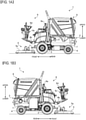
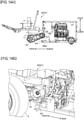
- Fig. 1A is a left side view of the riding type lawnmower 1 according to an embodiment.
- Fig. 1B is a right side view of the riding type lawnmower 1 according to the embodiment.
- the riding type lawnmower 1 is operated by an operator (also called a worker) seated on an operator's seat 6a provided on a front part of a running vehicle body 2.
- a longitudinal direction is a traveling direction in advancing of the riding type lawnmower 1, and a front side of the traveling direction is specified as a "front” and a rear side as a “rear”.
- the traveling direction of the riding type lawnmower 1 is a direction from the operator's seat 6a toward a steering wheel 6d in advancing of the riding type lawnmower 1 (see Figs. 1A and 1B ).
- a right-and-left direction is a direction horizontally orthogonal to the longitudinal direction.
- right and left are specified with respect to the "front" side. That is, in a state where the operator is seated on the operator's seat 6a and is directed to the front, the left hand side is "left” and the right hand side is “right”.
- an upper-and-lower direction is a vertical direction.
- the longitudinal direction, the right-and-left direction, and the upper-and-lower direction are orthogonal to each other three-dimensionally. Each direction is defined for convenience for ease of description, and the present invention is not limited by these directions.
- the riding type lawnmower 1 is called a machine body in some cases.
- the riding type lawnmower (hereinafter referred to as a lawnmower) 1 includes a pair of right and left wheels (front wheels) 3 on a front part of the running vehicle body 2 and a pair of right and left wheels (rear wheels) 4 on a rear part of the running vehicle body 2.
- the lawnmower 1 includes a mower 5 having a cutting blade rotating around a vertical shaft (a shaft along the upper-and-lower direction in Figs. 1A and 1B ) on a lower front side of the running vehicle body 2.
- the mower 5 is provided capable of elevation in front of the running vehicle body 2.
- the lawnmower 1 includes an operation portion 6 on the front part of the running vehicle body 2.
- the operation portion 6 includes the operator's seat 6a, a floor step 6b, a steering column 6c, and a steering wheel 6d.
- the floor step 6b is provided in front of the operator's seat 6a.
- the steering column 6c is installed upright on the front part of the floor step 6b.
- the steering wheel 6d is provided on the upper part of the steering column 6c.
- On the upper part of the steering column 6c an operation panel, various operation levers, various operation switches and the like are provided in addition to the steering wheel 6d.
- the lawnmower 1 includes a vehicle body frame 21 and an engine E (see Figs. 3A to 3C ) which will be described later forming the running vehicle body 2 on a rear part (on the rear of the operator's seat 6a) of the running vehicle body 2.
- the lawnmower 1 includes a bonnet 7 covering the vehicle body frame 21 and the engine E and a collector 8 provided above the bonnet 7 on the rear part of the running vehicle body 2.
- the collector 8 is a container accommodating grass and the like mowed by the mower 5 (hereinafter referred to as grass).
- the lawnmower 1 includes a blower case incorporating a blower therein on the rear part of the running vehicle body 2.
- the blower case and the collector 8 are connected by a duct.
- a chute is provided between the blower and the mower 5.
- the grass mowed by the mower 5 is sent to the blower from a mower deck 5a via the chute and is further conveyed by air to the collector 8 via the duct.
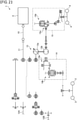
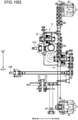
- FIG. 2 is a transmission diagram of the riding type lawnmower (lawnmower) 1 according to the embodiment.
- power (rotation power) output from the engine E is transmitted to a distribution transmission shaft 11 connected to an output shaft 10 of the engine E and is transmitted to a first PTO (power Take-off) shaft (also called a blower PTO shaft) 12A.
- the rotation power output from the blower PTO shaft 12A is transmitted to the aforementioned blower via a blower transmitting device (a gear transmitting device or the like), for example.
- the rotation power output from the distribution transmission shaft 11 is transmitted to a driving wheel via a running transmitting device.
- a hydraulic motor 13b is shifted by tilting of a trunnion shaft via a hydraulic pump 13a of a hydraulic continuously variable transmission (hereinafter, called HST (Hydro Static Transmission)) 13.
- HST Hydrau Static Transmission
- the lawnmower 1 is constituted capable of switching between two-wheel drive (2WD) and four-wheel drive (4WD).
- the driving wheels are any of the right and left front wheels 3 and the right and left rear wheels 4 (the right and left front wheels 3, for example) if the lawnmower 1 is two-wheel drive, and they are right and left front wheels 3 and the right and left rear wheels 4 if the lawnmower 1 is four-wheel drive.
- the rotation power output from the distribution transmission shaft 11 is transmitted to the front wheel 3 via the hydraulic pump 13a and the hydraulic motor 13b of the HST13 and via a gear transmitting device 14a and a differential mechanism 14b in a differential case 14. Moreover, the rotation power output from the distribution transmission shaft 11 is transmitted to the rear wheel 4 via the hydraulic pump 13a and the hydraulic motor 13b of the HST 13 and via the gear transmitting device 15a and the differential mechanism 15b in the differential case 15.
- the rotation power output from the distribution transmission shaft 11 is transmitted to a second PTO shaft (also called a mower PTO shaft) 12B.
- the rotation power output from a mower PTO shaft 12B is transmitted to the aforementioned cutting blade via a mower input shaft and the mower transmitting device in the mower deck 5a.
- a frame structure (vehicle body frame 21) of the running vehicle body 2 will be described.
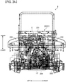
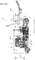
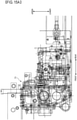
- Figs. 3A to 3C are explanatory views of the frame structure of the running vehicle body 2.
- Fig 3A illustrates a rear surface of the running vehicle body 2
- Fig. 3B illustrates a plan of the running vehicle body 2
- Fig. 3C illustrates a right side surface of the running vehicle body 2.
- the running vehicle body 2 includes the vehicle body frame 21.
- the vehicle body frame 21 is constituted by a front part 22 having a large right-and-left width and a rear part 23 having a small right-and-left width.
- the front part 22 and the rear part 23 of the vehicle body frame 21 are fixed by welding or the like with centers in the right-and-left direction of the front part 22 and the rear part 23 aligned with each other, for example.
- the operator's seat 6a is mounted on a rear half part, and the floor step 6b is formed on a front half part.
- the aforementioned HST13 and the differential case 14 are mounted in a suspended state.
- the HST13 is arranged on the rear part 23 side of the vehicle body frame 21.
- the rear part 23 of the vehicle body frame 21 includes an upper frame 231 and a lower frame 232.
- the upper frame 231 and the lower frame 232 are both rectangular frames elongated in the longitudinal direction.
- the rear part 23 of the vehicle body frame 21 includes an intermediate frame 233 connecting the upper frame 231 and the lower frame 232 in a vertically aligned state.
- the rear part 23 of the vehicle body frame 21 is a rectangular frame having a cuboid (box-shaped) shape elongated in the longitudinal direction by the upper frame 231, the lower frame 232, and the intermediate frame 233.
- the rear part 23 of the vehicle body frame 21 includes an engine mount portion 234 in which the engine E mounted on the lawnmower 1 (see Figs. 1A and 1B ) is arranged in the cuboid-shaped rectangular frame formed by the upper frame 231, the lower frame 232, and the intermediate frame 233.
- the engine mount portion 234 supports the engine E from below through a rubber material (rubber mount).
- the lower frame 232 supports the engine mount portion 234 from below.
- an axle case (rear-wheel axle case) 17 for accommodating the axle connecting the pair of right and left rear wheels 4 is mounted.
- the lower frame 232 is arranged lower than the rear-wheel axel case 17.
- the rear part 23 of the vehicle body frame 21 is formed as described above, and the lower frame 232 supporting the engine mount portion 234 from below is arranged lower than the rear-wheel axle case 17 so that the engine E is arranged at a low position in the vehicle body frame 21.
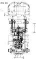
- Fig. 4 is an arrangement explanatory view of the four-wheel drive shaft 18.
- Fig. 4 illustrates a plan of the four-wheel drive shaft 18.
- the lawnmower 1 is constituted capable of being switched to a two-wheel drive (2WD) method driving only the right and left front wheels 3 and the four-wheel drive (4WD) method driving both the right and left front wheels 3 and the right and left rear wheels 4 as described above by a switching operation of a 4WD clutch provided on the operation portion 6, for example.
- the four-wheel drive shaft 18 is arranged between the pairs of right and left wheels (the right and left front wheels 3 and the right and left rear wheels 4) aligned in the longitudinal direction and extends along the longitudinal direction and transmits the rotation power from the engine E transmitted to either one of the front and rear drive wheels (front wheels 3) to the other drive wheels (rear wheels 4).
- the four-wheel drive shaft 18 has its front end portion connected to the HST13 side through a coupling 18a and has a rear end portion connected to the axle case 17 side of the rear wheels 4 through a coupling 18b.
- the four-wheel drive shaft 18 is arranged by being offset to the right-and-left direction so as to avoid the engine E arranged on the engine mount portion 234 (see Figs. 3B and 3C ) to one of right and left sides (to the right, for example).
- the engine E specifically, an oil pan arranged below the engine E
- the four-wheel drive shaft 18 do not interfere with each other anymore, and the engine E is arranged at a low position in the vehicle body frame 21.
- the power transmission mechanism mounted on the running vehicle body (see Fig. 3B ) is surrounded by a one-dot chain line for each type.
- the power transmission mechanism of the running vehicle body 2 is roughly divided into mechanic transmissions 19A and 19B, and an HST unit 19C including the HST13.
- a running load can be reduced as compared with hydraulic driving for driving the respective driving wheels by the hydraulic motor, for example.
- the engine E can be arranged at a low position in the machine body.
- a position of the center of gravity of the machine body can be lowered.
- the ground work can be carried out stably, and workability can be improved. If the position of the center of gravity of the machine body is low, it is particularly stable in an inclined work.
- the rear part 23 of the vehicle body frame 21 has the cuboid (box-shaped) rectangular frame structure, frame rigidity is improved, and a periphery of the engine E is made open, whereby accessibility to the engine E is improved. As a result, workability such as maintenance is improved.
- the engine E does not interfere with the four-wheel drive shaft 18, whereby the engine E can be arranged at a low position in the machine body.
- the position of the center of gravity of the machine body can be lowered, and by lowering the position of the center of gravity of the machine body, the ground work can be carried out stably, and workability can be improved.
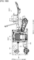
- FIGs. 5A and 5B are explanatory views of the connection structure of the HST unit 19C and the HST pedal 25.
- Fig. 5A illustrates a right side surface of the front part 22 of the vehicle body frame 21 (HST unit 19C and the HST pedal 25) and
- Fig. 5B illustrates an enlarged right side surface of the HST unit 19C and the HST pedal 25.
- the HST pedal 25 stepped on and operated by the operator when the machine body is moved forward/backward by operating a trunnion arm 13c (see Fig. 5B ) of the HST unit 19C (HST13) provided in a mission case 71 (see Figs. 15A and 15B ) is provided.
- the HST pedal 25 is arranged on the right side of the steering column 6c (see Fig. 1B ) on the floor step 6b.
- the HST pedal 25 includes a forward pedal 25a operated when the machine body is to be moved forward and a reverse pedal operated when the machine body is moved backward.
- the forward pedal 25a and the reverse pedal are arranged side by side in the right-and-left direction of the machine body.
- Figs. 5A and 5B illustrate only the forward pedal 25a.
- the HST pedal 25 realizes continuously variable transmission corresponding to forward acceleration, neutral, and reverse acceleration by adjustment of a trunnion opening of the HST13 in accordance with a stepped-on operation.
- a spring recovering force for example.
- two rods 26 are provided between the HST pedal 25 (25a) and the trunnion arm 13c of the HST unit 19C.
- the two rods 26 are arranged toward the longitudinal direction and connect the HST pedal 25 (25a) and the trunnion arm 13c.
- the forward rod 26a and the reverse rod 26b have front end portions connected to a front-side arm 28 connected to a rod member 27a extended from the HST pedal 25 and rear end portions connected to a rear-side arm 29 connected to a rod member 27b extended from the trunnion arm 13c, respectively.
- a link mechanism by the two rods 26 (26a, 26b) is realized. That is, when the forward pedal 25a is stepped on, the forward rod 26a is pulled to the front, and the trunnion arm 13c is operated (rotationally moved) to the forward side. When the reverse pedal is stepped on, the reverse rod 26b is pulled to the front, and the trunnion arm 13c is operated (rotationally moved) to the reverse side (the side opposite to the forward side).
- each of the forward rod 26a and the reverse rod 26b has an adjustment portion 30 (30a, 30b) provided in a middle position in the longitudinal direction so that they are adjustable.
- a turnbuckle is preferable, for example, as the adjustment portion 30.
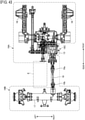
- Fig. 6A and Fig. 6B are explanatory views of the frame structure around the engine E.
- Fig. 7 is an arrangement explanatory view of an axle (an axle of the rear wheel 4 (rear-wheel axle) or also called a rear axle) 41.
- Fig. 6A illustrates a plan of the vehicle body frame 21
- Fig. 6B illustrates a right side surface of the vehicle body frame 21.
- a front-wheel transmission case 16 and a rear-wheel axle case 17 are assembled to the vehicle body frame 21.
- Fig. 6B also illustrates a frame constituting member 232a which will be described later provided in the lower frame 232.
- Fig. 7 illustrates an enlarged side surface of the rear-wheel axle 41.
- the vehicle body frame 21 is constituted by the front part 22 and the rear part 23, and the rear part 23 in them is formed having a cuboid (box-shaped) rectangular frame.
- the rear part 23 of the vehicle body frame 21 includes the upper frame 231, the lower frame 232, and the intermediate frame 233.
- the lower frame 232 among the upper frame 231, the lower frame 232, and the intermediate frame 233 is a main frame in the rear part 23 and as illustrated in Fig. 7 , is arranged below the rear-wheel axle 41. As a result, the lower center of gravity of the machine body is made possible.
- the lower frame 232 includes a plurality of frame constituting members 232a provided side by side in the right-and-left direction.
- the number of frame constituting members 232a is at least two or more (preferably two).
- the plurality of (two) frame constituting members 232a is arranged at an equal distance to the right and left from the center line L1 in the right and-left direction of the running vehicle body 2 (vehicle body frame 21) above the rear-wheel axle case 17.
- the rear wheel axle case 17 is provided capable of swing in a rolling direction of the machine body around a swing shaft 171.
- the swing shaft 171 is provided on the center line L1 in the right-and-left direction of the vehicle body frame 21. That is, the swing shaft 171 is provided in the middle in the right-and-left direction with respect to the two frame constituting members 232a.
- the frame constituting members 232a provided side by side in the right-and-left direction regulate a swing range of the rear-wheel axle case 17 swinging around the swing shaft 171.
- the lower frame 232 functions as a member for regulating the swing, a swing regulating member is not needed anymore, and the number of components can be reduced.
- Fig. 8 is an arrangement explanatory view of a controller/fuse 31.
- Fig. 8 illustrates an enlarged left side surface of the vehicle body frame 21.
- Fig. 8 illustrates the controller/fuse 31 in an enlarged manner in an A part.
- a mounting stay 32 of the controller/fuse 31 is provided inside the rear part 23 of the vehicle body frame 21 and on a lower part of the upper frame 231.
- the controller/fuse 31 is mounted on the mounting stay 32 and is arranged in a concentrated manner below the upper frame 231.
- controller/fuse 31 is arranged in the cuboid (box-shaped) rectangular frame in the concentrated manner on the rear part 23 of the vehicle body frame 21, accessibility to the controller/fuse 31 is improved. As a result, maintainability is improved. Moreover, the space can be effectively utilized.
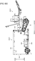
- Figs. 9A and 9B are arrangement explanatory views of a four-wheel drive unit 51.
- Fig. 9A illustrates a plan of the vehicle body frame 21
- Fig. 9B illustrates a right side surface of the vehicle body frame 21.
- the front-wheel transmission case 16, the rear-wheel axle case 17, the four-wheel drive shaft 18, and the HST unit 19C are assembled to the vehicle body frame 21.
- the four-wheel drive unit (also called an auto 4WD unit) 51 is arranged immediately after the HST unit 19C.
- the four-wheel drive unit 51 immediately after the HST unit 19C there is no more need to provide the four-wheel drive unit 51 on the rear-wheel axle case 17 side and thus, the rear-wheel axle case 17 can be constituted with a smaller size.
- a space for arranging the engine E (see Figs. 3A to 3C ) at a low position on the rear part 23 of the vehicle body frame 21 can be ensured.
- Figs. 10A and 10B are arrangement explanatory views of the radiator 61 and the air cleaner 62.
- Fig. 10A illustrates a plan of the vehicle body frame 21
- Fig. 10B illustrates a right side surface of the vehicle body frame 21.
- the radiator 61 is arranged on either one of the right and left side parts (right side part) of the rear part 23 of the vehicle body frame 21. Moreover, the air cleaner 62 is arranged on either one of the right and left side parts (right side part) of the rear part 23 of the vehicle body frame 21.
- the radiator 61 is arranged laterally so as to face the right-and-left direction. As described above, since the radiator 61 is arranged laterally, the radiator 61 is arranged on the side of the engine E, and they are not aligned in the longitudinal direction and thus, an entire length (longitudinal length) of the vehicle body 21 can be reduced, and size reduction of the machine body can be realized.
- the radiator 61 is covered by a radiator net 611 which will be described later on an outer side part.
- the air cleaner 62 is arranged on the rear of the radiator 61. Moreover, the air cleaner 62 is arranged by protruding outward from the rear part 23 of the vehicle body frame 21.
- the radiator 61 and the air cleaner 62 are connected by a pipeline (suction pipe) 63.
- the air cleaner 62 applies purification processing to air flowing into the suction pipe 63 and supplies it to the engine E (see Fig. 3B ).
- a lid 621 of the air cleaner 62 is arranged closer to the outer side than the rear part 23 of the vehicle body frame 21.
- the air cleaner 62 protrudes outward from the rear part 23 (the upper frame 231 and the lower frame 232) of the vehicle body frame 21 and thus, an access to the air cleaner 62 is made easy.
- the air cleaner 62 needs regular maintenance such as cleaning or replacement of a filter, but the maintenance of the air cleaner 62 can be made easily by that.
- the air cleaner 62 is arranged on the rear part 23 of the vehicle body frame 21 which is a cuboid-shaped rectangular frame, the air cleaner 62 can be arranged at a position where maintenance can be made easily and also can be stably arranged.
- Figs. 11A and 11B are explanatory views of the connection structure of the radiator 61 and the air cleaner 62.
- Fig. 11A illustrates plans of the radiator 6 1 and the air cleaner 62
- Fig. 11B illustrates right side surfaces of the radiator 61 and the air cleaner 62.
- the radiator 61 has a portion exposed to an outside (an outer side part) covered by the radiator net 611 so that dusts or the like do not enter from the outside of the machine body during suctioning by a radiator fan. Moreover, an end portion of the suction pipe 63 on the radiator 61 side is inserted into a hole 612 formed in the radiator net 611 and is arranged in an internal space of the radiator net 611. Thus, a suction port 631 of the suction pipe 63 is arranged in the internal space of the radiator net 611.
- connection structure as above since the end portion of the suction pipe 63 on the radiator 61 side is arranged in the internal space of the radiator net 611, suctioning of dusts or the like of the outside of the machine body can be prevented. As a result, clogging of the air cleaner 62 caused by suctioning of the dusts or the like can be prevented.
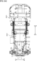
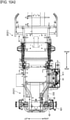
- FIGs. 12A and 12B are explanatory views of the attachment/detachment structure of the radiator net 611.
- Figs. 12A and 12B illustrate a rear surface of a radiator unit 64 including the radiator 61.
- Fig. 12A illustrates a state of the middle of mounting or removal of the radiator net 611 and
- Fig. 12B illustrates a state where the radiator net 611 has been mounted.
- the radiator unit 64 includes a radiator bracket 641, a fixing portion 642, and a supporting portion 643 in addition to the aforementioned radiator 61 and the radiator net 611.
- the radiator bracket 641 has a box shape, for example, and accommodates the radiator 61 therein.
- a surface directed to an outer side of the vehicle body frame 21 (see Fig. 3B ) is open, and the radiator net 611 is mounted on the open surface.
- the fixing portion 642 fixes the radiator net 611 when the radiator net 611 is mounted on the radiator bracket 641.
- the supporting portion 643 supports the radiator net 611 arranged on the open surface of the radiator bracket 641 from below when the radiator net 611 is mounted on the radiator bracket 641.
- the fixing portion 642 includes a fixing bar 642a and a fixing clip 642b.
- the fixing bar 642a is provided on the open surface of the radiator bracket 641 and has a bar portion crossing this surface in the longitudinal direction, for example.
- the fixing clip 642b is provided on an inner side surface of the box-shaped radiator net 611 and is engageable with the bar portion of the fixing bar 642a, for example.
- the supporting portion 643 is provided by protruding outward on a lower part of the radiator bracket 641, and a lower-end edge portion of the radiator net 611 is placed thereon.
- the supporting portion 643 is a hook extended in the longitudinal direction, for example.
- the radiator net 611 When the radiator net 611 is to be mounted on the radiator bracket 641, the lower end edge portion of the radiator net 611 is placed on the supporting portion 643 and is rotated to a closing direction with a portion placed on the supported portion 643 as a fulcrum so that the fixing clip 642b is engaged with the fixing bar 642a of the fixing portion 642.
- the radiator net 611 When the radiator net 611 is to be removed, it is rotated to the opening direction using the portion placed on the supporting portion 643 as a fulcrum so that the engagement of the fixing portion 642 is disengaged, and the radiator net 611 can be removed.
- the radiator net 611 can be easily mounted or removed without using a tool or the like. As a result, maintainability is improved.
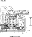
- FIGs. 13A and 13B are explanatory views of the engine mount structure.
- Fig. 13A illustrates the rear part 23 of the vehicle body frame 21 from upper left on the rear
- Fig. 13B illustrates the rear part 23 of the vehicle body frame 21 from upper right on the rear.
- the engine mount portion 234 supporting the engine E from below on the rear part 23 of the vehicle body frame 21 includes a bent plate 234a and a rib 234b.
- he bent plate 234a is provided on the lower frame 232 of the rear part 23 in the vehicle body frame 21.
- the bent plates 234a are provided in a pair of right and left, and they are inclined so that their respective upper parts are open to be directed to the outside of the machine body.
- the rib 234b is a reinforcing member of the bent plate 234a and provided along the upper-and-lower direction on a surface of the bent plate 234a to be the outside of the machine body.
- a rubber material (mount rubber) 234c for suppressing vibration transmitted to the engine E is provided on the upper part of the bent plate 234a.
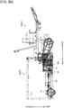
- Figs. 14A and 14B are explanatory views of the brake constitution.
- Fig. 14A illustrates a right side surface of the vehicle body frame 21.
- Fig. 14B illustrates enlarged perspective of the front-wheel transmission case 16.
- the front-wheel transmission case 16 for power transmission toward the front wheel 3 is provided on the front part 22 of the vehicle body frame 21.
- a cylindrical portion 161 is provided on a rear end portion of the front-wheel transmission case 16, and a brake mechanism 162 is incorporated in the cylindrical portion 161.
- the brake mechanism 162 includes a brake arm 162a.
- the brake arm 162a is provided across an inside and an outside of the cylindrical portion 161 and thus, rotation of a brake drum of the brake mechanism 162 incorporated in the cylindrical portion 161 during running of the machine body can be prevented. As a result, safety is improved.
- Figs. 15A and 15B are explanatory views of the clutches 72 and 73 disposed in the mission case 71.
- Fig. 15A illustrates an enlarged left side surface in the mission case 71
- Fig. 15B illustrates an enlarged plan in the mission case 71.
- the blower PTO clutch 72 for connecting/disconnecting power transmitted to the blower PTO shaft 12A is disposed in the mission case 71.
- the mower PTO clutch 73 for connecting/disconnecting the power transmitted to the mower PTO shaft 12B is disposed in the mission case 71.
- the blower PTO clutch 72 and the mower PTO clutch 73 use the same clutch (that is, a clutch of the same type).
- the two clutches 72 and 73 can be controlled with one clutch valve by providing one clutch valve for controlling the two clutches 72 and 73. That is, the clutch valve can be shared.
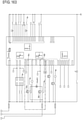
- Fig. 16 is an explanatory view of a driving circuit of the radiator fan 81.
- a portion relating to driving of the radiator fan 81 in each driving circuit of the lawnmower 1 is surrounded by a one-dot broken line.
- the radiator fan 81 is arranged between the radiator 61 (see Figs. 10A and 10B ) and the engine E (see Figs. 3B and 3C ).
- the radiator fan 81 is electronically driven and is capable of forward/reverse rotation.
- a driving motor 81a of the radiator fan 81 is rotated in either one of forward and reverse directions by switching an electric current of the driving motor 81a through two relays 83a and 83b on the basis of a rotation signal (forward rotation signal, reverse rotation signal) output from the controllers 82a and 82b.
- rotation of the radiator fan 81 (driving motor 81a) is switched between forward and reverse at a predetermined interval (time) such that the direction is reversed every five minutes.
- the forward rotation signal is output from the controller 82a for five minutes
- the reverse rotation signal is output from the controller 82b for ten seconds.
- An air-cooling fan for cooling the engine E may be provided on a downstream side of the radiator fan 81 and on an upstream side of the engine E. By providing the air-cooling fan, overheat of the engine E can be further prevented.
Landscapes
- Life Sciences & Earth Sciences (AREA)
- Environmental Sciences (AREA)
- Harvester Elements (AREA)
- Body Structure For Vehicles (AREA)
Applications Claiming Priority (1)
| Application Number | Priority Date | Filing Date | Title |
|---|---|---|---|
| JP2017151085A JP6834837B2 (ja) | 2017-08-03 | 2017-08-03 | 乗用芝刈り機 |
Publications (2)
| Publication Number | Publication Date |
|---|---|
| EP3437452A1 EP3437452A1 (en) | 2019-02-06 |
| EP3437452B1 true EP3437452B1 (en) | 2022-03-16 |
Family
ID=63143035
Family Applications (1)
| Application Number | Title | Priority Date | Filing Date |
|---|---|---|---|
| EP18186990.0A Active EP3437452B1 (en) | 2017-08-03 | 2018-08-02 | Riding type lawnmower |
Country Status (3)
| Country | Link |
|---|---|
| EP (1) | EP3437452B1 (enExample) |
| JP (1) | JP6834837B2 (enExample) |
| CN (1) | CN109379976B (enExample) |
Families Citing this family (4)
| Publication number | Priority date | Publication date | Assignee | Title |
|---|---|---|---|---|
| JP7327085B2 (ja) * | 2019-11-05 | 2023-08-16 | 井関農機株式会社 | 作業車両 |
| CN117202775A (zh) | 2021-09-18 | 2023-12-08 | 南京泉峰科技有限公司 | 骑乘式割草机、骑乘机器和动力工具的显示界面装置 |
| EP4231812A4 (en) * | 2021-09-18 | 2023-12-20 | Nanjing Chervon Industry Co., Ltd. | MOWING MACHINE |
| CN118696697B (zh) * | 2024-07-10 | 2024-12-03 | 南通进鲜港农业科技发展有限公司 | 一种农业用便于收集废草的智能除草机 |
Family Cites Families (17)
| Publication number | Priority date | Publication date | Assignee | Title |
|---|---|---|---|---|
| US4807904A (en) * | 1987-05-07 | 1989-02-28 | Simplicity Manufacturing, Inc. | Riding mower chassis having improved rear portion |
| JPH03123409A (ja) * | 1989-10-07 | 1991-05-27 | Kubota Corp | 乗用型芝刈機 |
| JPH04112115U (ja) * | 1991-03-19 | 1992-09-29 | 株式会社クボタ | 作業車のラジエータ支持構造 |
| US5475971A (en) * | 1994-09-20 | 1995-12-19 | T & M Technologies, Inc. | Riding mower |
| JPH09271237A (ja) * | 1996-04-09 | 1997-10-21 | Kubota Corp | ミッドマウント型乗用芝刈機 |
| JP3672458B2 (ja) * | 1999-06-08 | 2005-07-20 | 株式会社クボタ | 芝刈機 |
| JP3833092B2 (ja) * | 2001-09-28 | 2006-10-11 | 株式会社クボタ | 草刈り機 |
| JP4502861B2 (ja) * | 2005-03-30 | 2010-07-14 | 株式会社クボタ | 複合作業用のフレーム構造 |
| JP2007267625A (ja) | 2006-03-30 | 2007-10-18 | Iseki & Co Ltd | 乗用芝刈機 |
| JP5544825B2 (ja) * | 2009-10-30 | 2014-07-09 | 井関農機株式会社 | 乗用型田植機 |
| WO2011159293A1 (en) * | 2010-06-16 | 2011-12-22 | Husqvarna Ab | Light riding vehicle |
| JP5921158B2 (ja) * | 2011-11-17 | 2016-05-24 | 株式会社クボタ | 作業機 |
| DE102013222254B4 (de) * | 2013-10-31 | 2022-06-02 | Deere & Company | Erntemaschine mit gefederter Hinterachsanordnung |
| JP6322025B2 (ja) * | 2014-03-31 | 2018-05-09 | 株式会社クボタ | 芝刈機 |
| JP6555887B2 (ja) * | 2015-01-06 | 2019-08-07 | 株式会社クボタ | 草刈機 |
| JP6639833B2 (ja) * | 2015-08-28 | 2020-02-05 | 株式会社クボタ | 電動作業車両 |
| CN205530094U (zh) * | 2016-02-01 | 2016-08-31 | 大连海洋大学 | 多功能升降式环保车 |
-
2017
- 2017-08-03 JP JP2017151085A patent/JP6834837B2/ja active Active
-
2018
- 2018-08-02 EP EP18186990.0A patent/EP3437452B1/en active Active
- 2018-08-03 CN CN201810877568.XA patent/CN109379976B/zh active Active
Also Published As
| Publication number | Publication date |
|---|---|
| CN109379976A (zh) | 2019-02-26 |
| CN109379976B (zh) | 2021-11-16 |
| EP3437452A1 (en) | 2019-02-06 |
| JP2019024470A (ja) | 2019-02-21 |
| JP6834837B2 (ja) | 2021-02-24 |
Similar Documents
| Publication | Publication Date | Title |
|---|---|---|
| EP3437452B1 (en) | Riding type lawnmower | |
| JP6639833B2 (ja) | 電動作業車両 | |
| US10915600B2 (en) | Side-by-side diesel utility vehicle | |
| EP4173865A1 (en) | Electric tractor | |
| US10315709B2 (en) | Working vehicle | |
| JP2016196204A (ja) | 電動作業車両 | |
| US10604088B2 (en) | Tractor | |
| JP2002362174A (ja) | ホイール式走行作業車両 | |
| JP7113741B2 (ja) | 電動作業車 | |
| JP6879112B2 (ja) | 作業車両 | |
| US9155245B2 (en) | Work vehicle | |
| JP6534860B2 (ja) | トラクタ | |
| JPH10109654A (ja) | 乗用型芝刈機 | |
| JP5776540B2 (ja) | 作業車両 | |
| CN103958783B (zh) | 作业车辆及使其能够行驶的方法 | |
| JP7106446B2 (ja) | 電動作業車 | |
| JP6226817B2 (ja) | 水田作業機 | |
| EP4001605A1 (en) | Riding lawn mower | |
| JP6565976B2 (ja) | コンバインの原動部構造 | |
| EP4000369B1 (en) | Riding lawn mower | |
| JP2018034757A (ja) | 作業車 | |
| JP3833092B2 (ja) | 草刈り機 | |
| JP6560027B2 (ja) | トラクタ | |
| JP6815313B2 (ja) | 作業車 | |
| JP2011057222A (ja) | 水田作業機 |
Legal Events
| Date | Code | Title | Description |
|---|---|---|---|
| PUAI | Public reference made under article 153(3) epc to a published international application that has entered the european phase |
Free format text: ORIGINAL CODE: 0009012 |
|
| STAA | Information on the status of an ep patent application or granted ep patent |
Free format text: STATUS: REQUEST FOR EXAMINATION WAS MADE |
|
| 17P | Request for examination filed |
Effective date: 20180802 |
|
| AK | Designated contracting states |
Kind code of ref document: A1 Designated state(s): AL AT BE BG CH CY CZ DE DK EE ES FI FR GB GR HR HU IE IS IT LI LT LU LV MC MK MT NL NO PL PT RO RS SE SI SK SM TR |
|
| AX | Request for extension of the european patent |
Extension state: BA ME |
|
| GRAP | Despatch of communication of intention to grant a patent |
Free format text: ORIGINAL CODE: EPIDOSNIGR1 |
|
| STAA | Information on the status of an ep patent application or granted ep patent |
Free format text: STATUS: GRANT OF PATENT IS INTENDED |
|
| INTG | Intention to grant announced |
Effective date: 20210928 |
|
| GRAS | Grant fee paid |
Free format text: ORIGINAL CODE: EPIDOSNIGR3 |
|
| GRAA | (expected) grant |
Free format text: ORIGINAL CODE: 0009210 |
|
| STAA | Information on the status of an ep patent application or granted ep patent |
Free format text: STATUS: THE PATENT HAS BEEN GRANTED |
|
| AK | Designated contracting states |
Kind code of ref document: B1 Designated state(s): AL AT BE BG CH CY CZ DE DK EE ES FI FR GB GR HR HU IE IS IT LI LT LU LV MC MK MT NL NO PL PT RO RS SE SI SK SM TR |
|
| REG | Reference to a national code |
Ref country code: GB Ref legal event code: FG4D |
|
| REG | Reference to a national code |
Ref country code: CH Ref legal event code: EP Ref country code: DE Ref legal event code: R096 Ref document number: 602018032225 Country of ref document: DE |
|
| REG | Reference to a national code |
Ref country code: IE Ref legal event code: FG4D |
|
| REG | Reference to a national code |
Ref country code: AT Ref legal event code: REF Ref document number: 1475237 Country of ref document: AT Kind code of ref document: T Effective date: 20220415 |
|
| REG | Reference to a national code |
Ref country code: LT Ref legal event code: MG9D |
|
| REG | Reference to a national code |
Ref country code: NL Ref legal event code: MP Effective date: 20220316 |
|
| PG25 | Lapsed in a contracting state [announced via postgrant information from national office to epo] |
Ref country code: SE Free format text: LAPSE BECAUSE OF FAILURE TO SUBMIT A TRANSLATION OF THE DESCRIPTION OR TO PAY THE FEE WITHIN THE PRESCRIBED TIME-LIMIT Effective date: 20220316 Ref country code: RS Free format text: LAPSE BECAUSE OF FAILURE TO SUBMIT A TRANSLATION OF THE DESCRIPTION OR TO PAY THE FEE WITHIN THE PRESCRIBED TIME-LIMIT Effective date: 20220316 Ref country code: NO Free format text: LAPSE BECAUSE OF FAILURE TO SUBMIT A TRANSLATION OF THE DESCRIPTION OR TO PAY THE FEE WITHIN THE PRESCRIBED TIME-LIMIT Effective date: 20220616 Ref country code: LT Free format text: LAPSE BECAUSE OF FAILURE TO SUBMIT A TRANSLATION OF THE DESCRIPTION OR TO PAY THE FEE WITHIN THE PRESCRIBED TIME-LIMIT Effective date: 20220316 Ref country code: HR Free format text: LAPSE BECAUSE OF FAILURE TO SUBMIT A TRANSLATION OF THE DESCRIPTION OR TO PAY THE FEE WITHIN THE PRESCRIBED TIME-LIMIT Effective date: 20220316 Ref country code: BG Free format text: LAPSE BECAUSE OF FAILURE TO SUBMIT A TRANSLATION OF THE DESCRIPTION OR TO PAY THE FEE WITHIN THE PRESCRIBED TIME-LIMIT Effective date: 20220616 |
|
| REG | Reference to a national code |
Ref country code: AT Ref legal event code: MK05 Ref document number: 1475237 Country of ref document: AT Kind code of ref document: T Effective date: 20220316 |
|
| PG25 | Lapsed in a contracting state [announced via postgrant information from national office to epo] |
Ref country code: LV Free format text: LAPSE BECAUSE OF FAILURE TO SUBMIT A TRANSLATION OF THE DESCRIPTION OR TO PAY THE FEE WITHIN THE PRESCRIBED TIME-LIMIT Effective date: 20220316 Ref country code: GR Free format text: LAPSE BECAUSE OF FAILURE TO SUBMIT A TRANSLATION OF THE DESCRIPTION OR TO PAY THE FEE WITHIN THE PRESCRIBED TIME-LIMIT Effective date: 20220617 Ref country code: FI Free format text: LAPSE BECAUSE OF FAILURE TO SUBMIT A TRANSLATION OF THE DESCRIPTION OR TO PAY THE FEE WITHIN THE PRESCRIBED TIME-LIMIT Effective date: 20220316 |
|
| PG25 | Lapsed in a contracting state [announced via postgrant information from national office to epo] |
Ref country code: NL Free format text: LAPSE BECAUSE OF FAILURE TO SUBMIT A TRANSLATION OF THE DESCRIPTION OR TO PAY THE FEE WITHIN THE PRESCRIBED TIME-LIMIT Effective date: 20220316 |
|
| PG25 | Lapsed in a contracting state [announced via postgrant information from national office to epo] |
Ref country code: SM Free format text: LAPSE BECAUSE OF FAILURE TO SUBMIT A TRANSLATION OF THE DESCRIPTION OR TO PAY THE FEE WITHIN THE PRESCRIBED TIME-LIMIT Effective date: 20220316 Ref country code: SK Free format text: LAPSE BECAUSE OF FAILURE TO SUBMIT A TRANSLATION OF THE DESCRIPTION OR TO PAY THE FEE WITHIN THE PRESCRIBED TIME-LIMIT Effective date: 20220316 Ref country code: RO Free format text: LAPSE BECAUSE OF FAILURE TO SUBMIT A TRANSLATION OF THE DESCRIPTION OR TO PAY THE FEE WITHIN THE PRESCRIBED TIME-LIMIT Effective date: 20220316 Ref country code: PT Free format text: LAPSE BECAUSE OF FAILURE TO SUBMIT A TRANSLATION OF THE DESCRIPTION OR TO PAY THE FEE WITHIN THE PRESCRIBED TIME-LIMIT Effective date: 20220718 Ref country code: ES Free format text: LAPSE BECAUSE OF FAILURE TO SUBMIT A TRANSLATION OF THE DESCRIPTION OR TO PAY THE FEE WITHIN THE PRESCRIBED TIME-LIMIT Effective date: 20220316 Ref country code: EE Free format text: LAPSE BECAUSE OF FAILURE TO SUBMIT A TRANSLATION OF THE DESCRIPTION OR TO PAY THE FEE WITHIN THE PRESCRIBED TIME-LIMIT Effective date: 20220316 Ref country code: CZ Free format text: LAPSE BECAUSE OF FAILURE TO SUBMIT A TRANSLATION OF THE DESCRIPTION OR TO PAY THE FEE WITHIN THE PRESCRIBED TIME-LIMIT Effective date: 20220316 Ref country code: AT Free format text: LAPSE BECAUSE OF FAILURE TO SUBMIT A TRANSLATION OF THE DESCRIPTION OR TO PAY THE FEE WITHIN THE PRESCRIBED TIME-LIMIT Effective date: 20220316 |
|
| PG25 | Lapsed in a contracting state [announced via postgrant information from national office to epo] |
Ref country code: PL Free format text: LAPSE BECAUSE OF FAILURE TO SUBMIT A TRANSLATION OF THE DESCRIPTION OR TO PAY THE FEE WITHIN THE PRESCRIBED TIME-LIMIT Effective date: 20220316 Ref country code: IS Free format text: LAPSE BECAUSE OF FAILURE TO SUBMIT A TRANSLATION OF THE DESCRIPTION OR TO PAY THE FEE WITHIN THE PRESCRIBED TIME-LIMIT Effective date: 20220716 Ref country code: AL Free format text: LAPSE BECAUSE OF FAILURE TO SUBMIT A TRANSLATION OF THE DESCRIPTION OR TO PAY THE FEE WITHIN THE PRESCRIBED TIME-LIMIT Effective date: 20220316 |
|
| REG | Reference to a national code |
Ref country code: DE Ref legal event code: R097 Ref document number: 602018032225 Country of ref document: DE |
|
| PLBE | No opposition filed within time limit |
Free format text: ORIGINAL CODE: 0009261 |
|
| STAA | Information on the status of an ep patent application or granted ep patent |
Free format text: STATUS: NO OPPOSITION FILED WITHIN TIME LIMIT |
|
| PG25 | Lapsed in a contracting state [announced via postgrant information from national office to epo] |
Ref country code: DK Free format text: LAPSE BECAUSE OF FAILURE TO SUBMIT A TRANSLATION OF THE DESCRIPTION OR TO PAY THE FEE WITHIN THE PRESCRIBED TIME-LIMIT Effective date: 20220316 |
|
| 26N | No opposition filed |
Effective date: 20221219 |
|
| PG25 | Lapsed in a contracting state [announced via postgrant information from national office to epo] |
Ref country code: SI Free format text: LAPSE BECAUSE OF FAILURE TO SUBMIT A TRANSLATION OF THE DESCRIPTION OR TO PAY THE FEE WITHIN THE PRESCRIBED TIME-LIMIT Effective date: 20220316 |
|
| PG25 | Lapsed in a contracting state [announced via postgrant information from national office to epo] |
Ref country code: MC Free format text: LAPSE BECAUSE OF FAILURE TO SUBMIT A TRANSLATION OF THE DESCRIPTION OR TO PAY THE FEE WITHIN THE PRESCRIBED TIME-LIMIT Effective date: 20220316 |
|
| REG | Reference to a national code |
Ref country code: CH Ref legal event code: PL |
|
| PG25 | Lapsed in a contracting state [announced via postgrant information from national office to epo] |
Ref country code: LU Free format text: LAPSE BECAUSE OF NON-PAYMENT OF DUE FEES Effective date: 20220802 Ref country code: LI Free format text: LAPSE BECAUSE OF NON-PAYMENT OF DUE FEES Effective date: 20220831 Ref country code: CH Free format text: LAPSE BECAUSE OF NON-PAYMENT OF DUE FEES Effective date: 20220831 |
|
| PG25 | Lapsed in a contracting state [announced via postgrant information from national office to epo] |
Ref country code: IT Free format text: LAPSE BECAUSE OF FAILURE TO SUBMIT A TRANSLATION OF THE DESCRIPTION OR TO PAY THE FEE WITHIN THE PRESCRIBED TIME-LIMIT Effective date: 20220316 Ref country code: IE Free format text: LAPSE BECAUSE OF NON-PAYMENT OF DUE FEES Effective date: 20220802 |
|
| PG25 | Lapsed in a contracting state [announced via postgrant information from national office to epo] |
Ref country code: HU Free format text: LAPSE BECAUSE OF FAILURE TO SUBMIT A TRANSLATION OF THE DESCRIPTION OR TO PAY THE FEE WITHIN THE PRESCRIBED TIME-LIMIT; INVALID AB INITIO Effective date: 20180802 |
|
| PG25 | Lapsed in a contracting state [announced via postgrant information from national office to epo] |
Ref country code: MK Free format text: LAPSE BECAUSE OF FAILURE TO SUBMIT A TRANSLATION OF THE DESCRIPTION OR TO PAY THE FEE WITHIN THE PRESCRIBED TIME-LIMIT Effective date: 20220316 Ref country code: CY Free format text: LAPSE BECAUSE OF FAILURE TO SUBMIT A TRANSLATION OF THE DESCRIPTION OR TO PAY THE FEE WITHIN THE PRESCRIBED TIME-LIMIT Effective date: 20220316 |
|
| PG25 | Lapsed in a contracting state [announced via postgrant information from national office to epo] |
Ref country code: TR Free format text: LAPSE BECAUSE OF FAILURE TO SUBMIT A TRANSLATION OF THE DESCRIPTION OR TO PAY THE FEE WITHIN THE PRESCRIBED TIME-LIMIT Effective date: 20220316 |
|
| PG25 | Lapsed in a contracting state [announced via postgrant information from national office to epo] |
Ref country code: MT Free format text: LAPSE BECAUSE OF FAILURE TO SUBMIT A TRANSLATION OF THE DESCRIPTION OR TO PAY THE FEE WITHIN THE PRESCRIBED TIME-LIMIT Effective date: 20220316 |
|
| PGFP | Annual fee paid to national office [announced via postgrant information from national office to epo] |
Ref country code: BE Payment date: 20240820 Year of fee payment: 7 |
|
| PGFP | Annual fee paid to national office [announced via postgrant information from national office to epo] |
Ref country code: DE Payment date: 20250828 Year of fee payment: 8 |
|
| PGFP | Annual fee paid to national office [announced via postgrant information from national office to epo] |
Ref country code: GB Payment date: 20250822 Year of fee payment: 8 |
|
| PGFP | Annual fee paid to national office [announced via postgrant information from national office to epo] |
Ref country code: FR Payment date: 20250821 Year of fee payment: 8 |