EP3431406B1 - Entsorgungsverfahren für verpackungsbehälter - Google Patents
Entsorgungsverfahren für verpackungsbehälter Download PDFInfo
- Publication number
- EP3431406B1 EP3431406B1 EP16894274.6A EP16894274A EP3431406B1 EP 3431406 B1 EP3431406 B1 EP 3431406B1 EP 16894274 A EP16894274 A EP 16894274A EP 3431406 B1 EP3431406 B1 EP 3431406B1
- Authority
- EP
- European Patent Office
- Prior art keywords
- packaging container
- spout
- weakened portion
- container
- layer
- Prior art date
- Legal status (The legal status is an assumption and is not a legal conclusion. Google has not performed a legal analysis and makes no representation as to the accuracy of the status listed.)
- Active
Links
Images


Classifications
-
- B—PERFORMING OPERATIONS; TRANSPORTING
- B65—CONVEYING; PACKING; STORING; HANDLING THIN OR FILAMENTARY MATERIAL
- B65D—CONTAINERS FOR STORAGE OR TRANSPORT OF ARTICLES OR MATERIALS, e.g. BAGS, BARRELS, BOTTLES, BOXES, CANS, CARTONS, CRATES, DRUMS, JARS, TANKS, HOPPERS, FORWARDING CONTAINERS; ACCESSORIES, CLOSURES, OR FITTINGS THEREFOR; PACKAGING ELEMENTS; PACKAGES
- B65D5/00—Rigid or semi-rigid containers of polygonal cross-section, e.g. boxes, cartons or trays, formed by folding or erecting one or more blanks made of paper
- B65D5/02—Rigid or semi-rigid containers of polygonal cross-section, e.g. boxes, cartons or trays, formed by folding or erecting one or more blanks made of paper by folding or erecting a single blank to form a tubular body with or without subsequent folding operations, or the addition of separate elements, to close the ends of the body
- B65D5/06—Rigid or semi-rigid containers of polygonal cross-section, e.g. boxes, cartons or trays, formed by folding or erecting one or more blanks made of paper by folding or erecting a single blank to form a tubular body with or without subsequent folding operations, or the addition of separate elements, to close the ends of the body with end-closing or contents-supporting elements formed by folding inwardly a wall extending from, and continuously around, an end of the tubular body
-
- B—PERFORMING OPERATIONS; TRANSPORTING
- B65—CONVEYING; PACKING; STORING; HANDLING THIN OR FILAMENTARY MATERIAL
- B65D—CONTAINERS FOR STORAGE OR TRANSPORT OF ARTICLES OR MATERIALS, e.g. BAGS, BARRELS, BOTTLES, BOXES, CANS, CARTONS, CRATES, DRUMS, JARS, TANKS, HOPPERS, FORWARDING CONTAINERS; ACCESSORIES, CLOSURES, OR FITTINGS THEREFOR; PACKAGING ELEMENTS; PACKAGES
- B65D5/00—Rigid or semi-rigid containers of polygonal cross-section, e.g. boxes, cartons or trays, formed by folding or erecting one or more blanks made of paper
- B65D5/36—Rigid or semi-rigid containers of polygonal cross-section, e.g. boxes, cartons or trays, formed by folding or erecting one or more blanks made of paper specially constructed to allow collapsing and re-erecting without disengagement of side or bottom connections
- B65D5/3607—Rigid or semi-rigid containers of polygonal cross-section, e.g. boxes, cartons or trays, formed by folding or erecting one or more blanks made of paper specially constructed to allow collapsing and re-erecting without disengagement of side or bottom connections formed by folding or erecting a single blank
- B65D5/3614—Rigid or semi-rigid containers of polygonal cross-section, e.g. boxes, cartons or trays, formed by folding or erecting one or more blanks made of paper specially constructed to allow collapsing and re-erecting without disengagement of side or bottom connections formed by folding or erecting a single blank to form a tubular body, at least one of the ends of the body remaining connected
- B65D5/3628—Rigid or semi-rigid containers of polygonal cross-section, e.g. boxes, cartons or trays, formed by folding or erecting one or more blanks made of paper specially constructed to allow collapsing and re-erecting without disengagement of side or bottom connections formed by folding or erecting a single blank to form a tubular body, at least one of the ends of the body remaining connected collapsed along median lines of two opposite sides of the rectangular tubular body
-
- B—PERFORMING OPERATIONS; TRANSPORTING
- B65—CONVEYING; PACKING; STORING; HANDLING THIN OR FILAMENTARY MATERIAL
- B65D—CONTAINERS FOR STORAGE OR TRANSPORT OF ARTICLES OR MATERIALS, e.g. BAGS, BARRELS, BOTTLES, BOXES, CANS, CARTONS, CRATES, DRUMS, JARS, TANKS, HOPPERS, FORWARDING CONTAINERS; ACCESSORIES, CLOSURES, OR FITTINGS THEREFOR; PACKAGING ELEMENTS; PACKAGES
- B65D5/00—Rigid or semi-rigid containers of polygonal cross-section, e.g. boxes, cartons or trays, formed by folding or erecting one or more blanks made of paper
- B65D5/42—Details of containers or of foldable or erectable container blanks
- B65D5/72—Contents-dispensing means
- B65D5/74—Spouts
- B65D5/746—Spouts formed separately from the container
-
- B—PERFORMING OPERATIONS; TRANSPORTING
- B65—CONVEYING; PACKING; STORING; HANDLING THIN OR FILAMENTARY MATERIAL
- B65D—CONTAINERS FOR STORAGE OR TRANSPORT OF ARTICLES OR MATERIALS, e.g. BAGS, BARRELS, BOTTLES, BOXES, CANS, CARTONS, CRATES, DRUMS, JARS, TANKS, HOPPERS, FORWARDING CONTAINERS; ACCESSORIES, CLOSURES, OR FITTINGS THEREFOR; PACKAGING ELEMENTS; PACKAGES
- B65D5/00—Rigid or semi-rigid containers of polygonal cross-section, e.g. boxes, cartons or trays, formed by folding or erecting one or more blanks made of paper
- B65D5/02—Rigid or semi-rigid containers of polygonal cross-section, e.g. boxes, cartons or trays, formed by folding or erecting one or more blanks made of paper by folding or erecting a single blank to form a tubular body with or without subsequent folding operations, or the addition of separate elements, to close the ends of the body
- B65D5/06—Rigid or semi-rigid containers of polygonal cross-section, e.g. boxes, cartons or trays, formed by folding or erecting one or more blanks made of paper by folding or erecting a single blank to form a tubular body with or without subsequent folding operations, or the addition of separate elements, to close the ends of the body with end-closing or contents-supporting elements formed by folding inwardly a wall extending from, and continuously around, an end of the tubular body
- B65D5/067—Gable-top containers
-
- B—PERFORMING OPERATIONS; TRANSPORTING
- B65—CONVEYING; PACKING; STORING; HANDLING THIN OR FILAMENTARY MATERIAL
- B65D—CONTAINERS FOR STORAGE OR TRANSPORT OF ARTICLES OR MATERIALS, e.g. BAGS, BARRELS, BOTTLES, BOXES, CANS, CARTONS, CRATES, DRUMS, JARS, TANKS, HOPPERS, FORWARDING CONTAINERS; ACCESSORIES, CLOSURES, OR FITTINGS THEREFOR; PACKAGING ELEMENTS; PACKAGES
- B65D5/00—Rigid or semi-rigid containers of polygonal cross-section, e.g. boxes, cartons or trays, formed by folding or erecting one or more blanks made of paper
- B65D5/42—Details of containers or of foldable or erectable container blanks
- B65D5/54—Lines of weakness to facilitate opening of container or dividing it into separate parts by cutting or tearing
- B65D5/5445—Lines of weakness to facilitate opening of container or dividing it into separate parts by cutting or tearing for dividing a tubular body into separate parts
-
- B—PERFORMING OPERATIONS; TRANSPORTING
- B65—CONVEYING; PACKING; STORING; HANDLING THIN OR FILAMENTARY MATERIAL
- B65D—CONTAINERS FOR STORAGE OR TRANSPORT OF ARTICLES OR MATERIALS, e.g. BAGS, BARRELS, BOTTLES, BOXES, CANS, CARTONS, CRATES, DRUMS, JARS, TANKS, HOPPERS, FORWARDING CONTAINERS; ACCESSORIES, CLOSURES, OR FITTINGS THEREFOR; PACKAGING ELEMENTS; PACKAGES
- B65D5/00—Rigid or semi-rigid containers of polygonal cross-section, e.g. boxes, cartons or trays, formed by folding or erecting one or more blanks made of paper
- B65D5/42—Details of containers or of foldable or erectable container blanks
- B65D5/72—Contents-dispensing means
- B65D5/74—Spouts
- B65D5/741—Spouts for containers having a tubular body
-
- B—PERFORMING OPERATIONS; TRANSPORTING
- B65—CONVEYING; PACKING; STORING; HANDLING THIN OR FILAMENTARY MATERIAL
- B65D—CONTAINERS FOR STORAGE OR TRANSPORT OF ARTICLES OR MATERIALS, e.g. BAGS, BARRELS, BOTTLES, BOXES, CANS, CARTONS, CRATES, DRUMS, JARS, TANKS, HOPPERS, FORWARDING CONTAINERS; ACCESSORIES, CLOSURES, OR FITTINGS THEREFOR; PACKAGING ELEMENTS; PACKAGES
- B65D5/00—Rigid or semi-rigid containers of polygonal cross-section, e.g. boxes, cartons or trays, formed by folding or erecting one or more blanks made of paper
- B65D5/36—Rigid or semi-rigid containers of polygonal cross-section, e.g. boxes, cartons or trays, formed by folding or erecting one or more blanks made of paper specially constructed to allow collapsing and re-erecting without disengagement of side or bottom connections
- B65D5/3607—Rigid or semi-rigid containers of polygonal cross-section, e.g. boxes, cartons or trays, formed by folding or erecting one or more blanks made of paper specially constructed to allow collapsing and re-erecting without disengagement of side or bottom connections formed by folding or erecting a single blank
- B65D5/3614—Rigid or semi-rigid containers of polygonal cross-section, e.g. boxes, cartons or trays, formed by folding or erecting one or more blanks made of paper specially constructed to allow collapsing and re-erecting without disengagement of side or bottom connections formed by folding or erecting a single blank to form a tubular body, at least one of the ends of the body remaining connected
- B65D5/3621—Rigid or semi-rigid containers of polygonal cross-section, e.g. boxes, cartons or trays, formed by folding or erecting one or more blanks made of paper specially constructed to allow collapsing and re-erecting without disengagement of side or bottom connections formed by folding or erecting a single blank to form a tubular body, at least one of the ends of the body remaining connected collapsed along two fold lines of the tubular body
Definitions
- the present invention relates to a disposal method for a packaging container.
- Some packaging containers are formed of a sheet material, such as one disclosed in PTL 1, which is a laminate of a paper substrate layer and a sealant layer made of a thermoplastic resin, with a barrier layer, such as an aluminum foil, aluminum deposited film, or inorganic oxide deposited film, being interposed therebetween.
- a packaging container is formed by folding this sheet material into a box shape, and sealing the ends of the sheet material with each other.
- packaging containers have a gable top panel, which is provided with a spout plug made of polyethylene or the like, so that the liquids inside the container can be poured out.
- the spout plug may be separated from the container body made of the paper sheet material, by opening up the top sealing portion and cutting the container body around the spout plug with scissors or the like.
- the container body is disassembled to reduce the volume of the refuse before being discarded.
- PTL 2 discloses a liquid packaging paper container having a container body sealed by overlapping both ends of the paper base sheet.
- the container body has a side sealing portion provided with a pull tab which is peelable via a peelable layer that is formed of an easily peelable tape-shaped film.
- the pull tab is pulled to peel off the side sealing portion, or the pull tab provided to a side panel is pulled to break the side panel to facilitate separation of the liquid packaging paper container body into its constituent parts.
- PTL 3 discloses liquid packaging paper container having a strip separator provided in a lower part of the container body. According to this liquid packaging paper container, the strip separator is separated from the container body and then two cutting lines are cut to allow at least an outermost layer and a paper base layer to be peeled from a barrier layer.
- PTL 4 discloses a paper packaging body where a spout having an easily-breakable portion is attached to the paper container having a folding guiding line. According to this paper packaging body, the paper container is folded along the folding guiding line to break the easily-breakable portion of the spout, so that the spout can be separated from the paper container.
- PTL 5 and PTL 6 are earlier European patent applications, which disclose alternative disposal methods for packaging containers.
- the liquid packaging paper container of PTL 2 needs to have the easily peelable tape-shaped film, while there is a concern that sealing of the bonding portions of the trunk may become unstable due to the presence of the easily peelable tape-shaped film. According to the method disclosed in PTL 4, although the spout can be detached, the paper container body cannot be disassembled.
- the present invention has been made in light of the issues set forth above, and has an object to provide a disposal method for a packaging container that allows the packaging container to be stably disassembled.
- An aspect of the present invention for solving the issues set forth above is a disposal method for a packaging container as specified in claim 1.
- the present invention provides a disposal method for a packaging container that allows the packaging container to be stably disassembled.
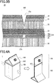
- Fig. 1 is a perspective view illustrating a packaging container 1 to be used in a disposal method for the packaging container 1 according to a non-claimed mode.
- the packaging container 1 is formed by folding a blank into a box shape and sealing the ends with each other.
- the packaging container 1 is made up of a top 101, a trunk 102 and a bottom 103.
- the top 101 is made up of two top panels 106.
- One of the top panels 106 is provided with a spout plug 104 having a spout for pouring liquid contained in the packaging container 1, and a cap for closing the spout.
- the packaging container 1 is linearly provided with a weakened portion 105 around the trunk at a level where parts of the linear weakened portion 105 align with each other in plan view when the packaging container 1 is compressed.
- Fig. 2 shows a blank 10 that is a material for the packaging container 1.
- the packaging container 1 includes the top panels 106 forming the top 101, side panels 109 forming the trunk 102, and bottom panels 110 forming the bottom 103.
- the blank 10 has a sealing portion 111 at an end.
- the blank 10 is folded along the dash-dot line of Fig. 2 and the sealing portion 111 is sealed to the other end to form the blank 10 into a box shape.
- One of the top panels 106 is provided with a spout opening 112 where the spout is inserted and fixed.
- the linear weakened portion 105 is formed in an area where the top 101 contacts the side panels 109.
- the linear weakened portion 105 extends in the width direction of the trunk 102 (horizontal direction as viewed in Fig. 2 ).
- Figs. 3A and 3B each show a schematic cross-sectional view of an example of a laminated structure of a sheet material 20 used for the blank 10. From the outside toward the inside of the packaging container 1, the sheet material 20 includes a printed layer 28 / a thermoplastic resin layer 21 / a paper base layer 22 / an adhesive resin layer 23 / a barrier layer 24 / an adhesive layer 25 / a sealant layer 26 in this order. The difference between the examples shown in Figs. 3A and 3B will be described later.
- the weakened portion 105 of the sheet material 20 is configured by groove-shaped score lines 27a and 27b which are formed with a predetermined depth at least in the paper base layer 22 and the barrier layer 24.
- the score line 27b of the barrier layer 24 is formed so as to align with the score line 27a of the paper base layer 22.
- the score line 27a is preferably provided at a depth not penetrating the barrier layer 24, but there is no problem if it partially penetrates the barrier layer, because penetrating the barrier layer in a partial small range would not affect the barrier properties.
- the score line 27a may be formed at least in the paper base layer 22, or, in addition to the paper base layer 22, may be formed, as shown in Figs. 3A and 3B , in the thermoplastic resin layer 21 and the printed layer 28 both of which are laminated on the outer side of the paper base layer 22.
- the score line 27a may be formed with a depth of allowing the paper base layer 22 to ensure strength of the packaging container 1.
- the score line 27a may be formed through a half blanking process or a full blanking process by use of a blade die. When using a full blanking process, the score line 27a may be formed in a perforated shape to ensure strength of the packaging container 1.
- the score line 27b may be formed by laser irradiation after bonding surfaces of the barrier layer. However, when forming the score line 27b before bonding of the barrier layer, half or full blanking process may be used.
- the score line 27b may be formed by laser processing even before bonding of the barrier layer.
- the score line 27b may also be formed in a perforated shape to ensure strength.
- the thermoplastic resin layer 21 may be formed on the paper base layer 22 such as by extrusion lamination, using a low-density polyethylene resin (LDPE), a linear low-density polyethylene resin (LLDPE), or the like.
- LDPE low-density polyethylene resin
- LLDPE linear low-density polyethylene resin
- a printed layer 28 may be provided to display a pattern or product information.
- the printed layer 28 may be formed through a method such as of gravure printing or offset printing, by using a well-known ink. Corona treatment or other adhesion enhancing treatment may be applied to the thermoplastic resin layer 21 to enhance adhesion thereof to the printed layer 28.
- An overcoat layer may be provided on the outer side of the printed layer 28 to improve wear resistance or surface decorativeness.
- paperboard such as milk carton base paper may be used.
- Basis weight and density may be appropriately selected depending on the capacity and design of the container, but it is preferable that the basis weight is in the range of 200 g/m 2 or more and 500 g/m 2 or less, and the density is in the range of 0.6 g/cm 3 or more and 1.1 g/cm 3 or less.
- the adhesive resin layer 23 is made of a polyolefin-based resin that is able to bond the paper base layer 22 to the barrier layer 24.
- high density polyethylene resin HDPE
- medium density polyethylene resin MDPE
- LDPE low density polyethylene resin
- LLDPE LLDPE
- ethylene methacrylic acid copolymer EAA
- EAA ethylene acrylic acid copolymer
- PP polypropylene
- an adhesive resin layer 23 with a thickness of 10 ⁇ m or more and 60 ⁇ m or less is used.
- corona treatment, ozone treatment, anchor coating or the like may be applied to a surface of the paper base layer 22 or the barrier layer 24.
- an adhesive layer using a dry laminate adhesive or the like may be provided instead of the adhesive resin layer.
- Films used for the barrier layer 24 may be deposited films including a base film 24a, and a vapor-deposited layer 24b on which a metal such as aluminum, or silica, alumina or the like is vapor-deposited, and a laminated film in which a metal foil 24c such as of aluminum is dry-laminated on a base film 24a.
- the barrier layer 24 is a deposited film configured by a base film 24a, and a vapor-deposited layer 24b provided on a surface serving as an inner surface of the packaging container 1.
- the barrier layer 24 is a laminated film configured by a base film 24a, and a metal foil 24c provided on a surface serving as an outer surface of the packaging container 1. If a deposited film is used, the thickness of the vapor-deposited layer is preferably in the range of 5 nm or more and 100 nm or less. If a laminated film is used, the thickness of the metal foil is preferably in the range of 5 ⁇ m or more and 15 ⁇ m or less. If a laminated film is used and the score line 27b is formed by irradiating laser, the barrier layer 24 is laminated such that, as shown in Fig. 3B , the metal foil 24c faces the adhesive resin layer 23.
- the barrier layer 24 includes a polyethylene terephthalate film that has been subjected to barrier coating, and a barrier film made of a barrier material such as EVOH.
- the base film 24a Materials that can be used for the base film 24a include a resin film such as of polyethylene terephthalate (PET), nylon, polypropylene (PP) or the like.
- PET polyethylene terephthalate
- PP polypropylene
- the base film 24a may have a thickness in the range of 6 ⁇ m or more and 25 ⁇ m or less, but may preferably have a thickness of 12 ⁇ m or more to prevent contraction due to the heat of laser.
- an adhesive for dry lamination or an adhesive for non-solvent lamination may be used, or a polyolefin-based resin may be extruded for adhesion.
- the adhesive layer 25 preferably has a thickness in the range of 5 ⁇ m or more and 20 ⁇ m or less.
- the quantity of dry coating is preferably in the range of 0.5 g/m 3 or more and 7.0 g/m 3 or less.
- sealant layer 26 Materials that can be used for the sealant layer 26 include HDPE, MDPE, LDPE, LLDPE and the like. A layer partially containing polybutene may be additionally provided. Of the materials mentioned above, LLDPE is particularly suitable, with a preferable density being 0.925 or less and a preferable melt index (MI) being 4 or more.
- the sealant layer 26 preferably has a thickness in the range of 30 ⁇ m or more and 100 ⁇ m or less.
- a non-stretched film produced by a T-die method or inflation method is preferably used for the sealant layer 26.
- FIGs. 4A , 4B and 4C show the disposal method for the packaging container 1 according to the non-claimed mode. Referring to Figs. 4A , 4B and 4C , individual steps will be described.
- Fig. 4A shows a step of compressing the packaging container 1.
- the user of the packaging container 1 compresses the trunk 102 of the packaging container 1 by compressing opposing two panels among the side panels 109 constituting the trunk 102 in a direction for the two panels to contact each other.
- the two compressed side panels 109 extend downward from the respective top panels 106.
- the remaining two panels 109 orthogonally joining the former two panels are folded inward of the packaging container 1 by the compression.
- the compressed packaging container 1 is shown on the right in Fig. 4A .
- parts of the weakened portion 105 formed all around the trunk 102 are aligned in plan view.
- Fig. 4B shows a step of folding and breaking the packaging container 1 along the weakened portion 105. In this step, the user folds the compressed packaging container 1 along the weakened portion 105 as shown in Fig. 4B .
- the user may fold the compressed packaging container 1 in the direction opposite to the initial folding direction, along the weakened portion 105 .
- the folding direction of the packaging container 1 may only be one, as long as the breakage sufficient for facilitating the separating step described below is caused.
- Fig. 4C shows a step of separating part of the packaging container 1, whose weakened portion 105 has been broken, from the rest of the container along the broken portion.
- the user pulls away the top 101 along the weakened portion 105 starting from the broken portion to separate the top 101 from the trunk 102. Since at least part of the weakened portion 105 has been broken, the user can pull away the top 101 along the weakened portion 105 with only a little strength in the folding and breaking step.
- the packaging container 1 is separated into the top 101 and the trunk 102.
- Fig. 5 is a perspective view illustrating a packaging container 3 to be used in a disposal method for the packaging container 3 according to an embodiment of the present invention.
- the packaging container 3 includes a container body 100 and a spout plug 104.
- the container body 100 is formed by folding a blank made of a processed sheet material into a box shape, and sealing the ends with each other.
- the spout plug 104 is a pouring tool made of a resin.
- the container body 100 includes a top 101 that serves as a top part when the container body 100 stands upright, a trunk 102 that serves as side panels, and a bottom 103 that serves as a bottom part.
- the top 101 includes two top panels 106 (106a, 106b), and inward-folding panels 107 and outward-folding panels 108 which are both folded in between the top plates 106.
- the top panel 106a is provided with a circular spout opening 112.
- the spout plug 104 includes a spout 104a and a cap 104b, and is mounted to the spout opening 112.
- the top 101 is provided with a weakened portion 105 having a lowered breaking strength in a width direction that is a horizontal direction when the container body stands upright.
- the sheet material one having a layer structure similar to that of the packaging container 1 used in the disposal method according to the non-claimed mode may be used.
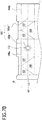
- Fig. 6 is a plan view illustrating a blank 12 that is an example of a blank serving as the material for the container body 100.
- the blank 12 has the top panels 106a and 106b, and the inward- and outward-folding panels 107 and 108 configuring the top 101, four side panels 109 configuring the trunk 102, bottom panels 110 configuring the bottom 103, and a sealing portion 111 formed at an end.
- the blank 12 is folded along the dash-dot lines of Fig. 6 , and the sealing portion 111 is sealed to the opposite end to form the blank 12 into a box shape.
- the spout opening 112 for inserting and fixing the spout plug 104 is formed near the center of the top panel 106a.
- the weakened portion 105 is linearly formed substantially all around the top panels 106a and 106b, the inward-folding panels 107 and the outward-folding panels 108 in the width direction that is the horizontal direction when the container body 100 stands upright. Part of the weakened portion 105 is interrupted by the spout opening 112. Namely, the crease formed when the container body 100 is folded along the weakened portion 105 crosses over the spout opening 112.
- Fig. 7A is a plan view illustrating a top 101 and the vicinity thereof of a blank 13 that is a modification of the blank 12.
- the blank 13 differs from the blank 12 in the position of the weakened portion.
- the blank 13 has a weakened portion 105' including weakened portions 105'a and 105'b which are each formed in a predetermined region crossing the boundary between the top panel 106a or 106b and the inward-folding panel 107. Both of these weakened portions are linearly formed extending in the width direction that is the horizontal direction when the container body 100 stands upright. The crease created by folding the container body 100 along the weakened portion 105' crosses over the spout opening 112.
- Fig. 7B is a plan view illustrating a top 101 and the vicinity thereof of a blank 14 that is a modification of the blank 12.
- the blank 14 differs from the blank 12 in the position of the weakened portion.
- the blank 14 has a weakened portion 105" which includes not only a weakened portion 105a" formed at the same position as that of the weakened portion 105 of the blank 12, but also a weakened portion 105b" formed around the spout opening 112.
- the crease created by folding the container body 100 along the weakened portion 105a" crosses over the spout opening 112.
- the crease created by folding the container body 100 along the weakened portion 105a" only has to cross over the spout opening 112, and accordingly, may or may not contact the weakened portion 105b" or the spout opening 112.
- the weakened portion 105 should include the weakened portion 105' or the weakened portion 105" unless otherwise mentioned.
- Sheet materials used for the blanks below may be ones similar to the one of the packaging container 1 used in the disposal method according to the non-claimed mode.
- Fig. 8A is a cross-sectional view illustrating the spout 104a.
- the spout 104a includes a cylindrical side wall 301, a disk-like flange 302 extending outward from a lower end of the side wall 301, a disk-like partition wall 303 internally formed at the lower end of the side wall 301 to close the interior of the packaging container against the exterior, and a pull tab 304 extending upward from the partition wall 303 and used when the user detaches the partition wall 303.
- the side wall 301 has an outer periphery in which an external screw 305 is formed for threadable engagement with an internal screw formed in the inner periphery of a cap 104b.
- the spout 104a is fixed by the flange 302 being bonded to the top panel 106a around the spout opening 112 by ultrasonic welding or the like.
- the side wall 301 has a lower part that is near the joint between itself and the flange 302, where a thin portion 306 is continuously or intermittently formed in the outer periphery of the side wall 301, with the thickness being reduced.
- Fig. 8B shows a spout 104a' according to a modification of the spout 104a.
- the spout 104a' differs from the spout 104a in the position where a thin portion 306' is formed.
- the thin portion 306' is annularly formed in a continuous or intermittent manner on the lower surface of the flange 302 by reducing the thickness of the flange 302.
- the surface for forming the thin portion is not limited to the lower surface, but may be the upper surface, or may be both.
- Fig. 8C shows a spout 104a" according to a modification of the spout 104a.
- the spout 104a" differs from the spout 104a in the presence or absence of the thin portion 306. As shown in Fig. 8C , the spout 104a" has no thin portion 306.
- the thin portion provided in the spout 104a and the spout 104a' is at least partially broken, and as will be described later, by folding the container body along the weakened portion.
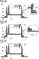
- FIGs. 9A and 9B show a disposal method according to the present invention. Referring to Figs. 9A and 9B , individual steps of the present embodiment will be described. The following description addresses a disposal method for the container body 100 and the spout 104a, using the blank 12.
- Fig. 9A shows a step of compressing the packaging container 3.
- the user of the packaging container 3 compresses the body 102 by pushing the two opposed side panels 109 extending below the top panels 106 in a direction of making these side plates contact each other.
- the two side panels 109 respectively contacting the side panels 109 to be pushed are folded inward of the packaging container 3, and the trunk 102 and the top 101 are compressed.
- Fig. 9B shows a step of folding the packaging container 3 along the weakened portion 105.
- the user folds the top panels 106 along the weakened portion 105.
- a crease created in the top panels 106 crosses over the spout opening 112.
- the spout 104a Since the crease created in the top panels 106 crosses over the spout opening 112, part of the flange 302 of the spout 104a mounted to the spout opening 112 bears a load and is folded toward the same direction as that of the top panel 106a.
- the spout 104a if provided with the thin portion 306, is at least partially broken, as shown on the right in Fig. 9B , at the thin portion 306 with the imposition of the load.
- Fig. 10A shows on the left a step of separating at least part of the spout plug 104 from the packaging container 3. Since the thin portion 306 of the spout 104a has been broken in the previous step, the user can separate the spout plug 104 from the packaging container 3 with only a little strength using this part as a starting point.
- Fig. 10A shows on the right a step of breaking the packaging container 3 along the weakened portion 105.
- the user folds the top panels 106 along the weakened portion 105.
- the top panels 106 may be folded more than once in both directions.
- breaking of the weakened portion 105 proceeds. If the weakened portion 105 has been broken over a sufficient length through the first folding step, the present step may be omitted.
- Fig. 10B shows on the left a step of separating part of the top panels 106 from the packaging container 3 along the weakened portion 105.
- the user tears apart and separates part of the top panels 106 from the packaging container 3 along the weakened portion 105 and the folded portion. Since at least part of the weakened portion 105 has been broken in the previous step, the user can separate the upper part of the top panels 106 with a little strength starting from the weakened portion 105.
- the packaging container 3 is separated into the upper part of the top panels 106, the trunk 102 and the spout plug 104.
- the spout plug can be easily separated with only a little strength.
- a weakened portion is provided in the width direction of the packaging container 3, there is a merit of being able to easily grip the container by hand on the upper and lower sides of the weakened portion and easily folding the packaging container 3.
- part of the top panels 106 can be easily separated from the packaging container 3, the subsequent separation of the trunk is facilitated.
- detachment of the spout plug and separation of the trunk can be done in a series of steps, so that it would not be bothersome for the consumers to take the procedure of separation.
- the packaging container can be appropriately disposed of for recycling.
- a weakened portion is provided in the height direction orthogonal to the width direction of the packaging container 3, it is necessary to grip the container by hand on the left and right sides of the weakened portion and to fold the container including the top sealing portion which is firmly sealed and has high stiffness. Therefore, it is difficult to grip the packaging container 3 and a large strength is needed compared to the case where the weakened portion is provided in the width direction.
- the direction of forming the weakened portion is preferably the width direction rather than the height direction of the packaging container 3.
- the disposal method described above can be applied to any of the combinations of the container body produced from the blank 12 or 13, with the spouts 104a, 104a' or spout 104a".
- Packaging containers according to Examples 1 to 3 were prepared to evaluate the disposal method for the packaging container according to the present invention.
- a sheet material to be used for the packaging container was prepared by laminating a printed layer / LDPE (18 ⁇ m) / paper base layer (400 g/m 2 ) / EMAA (30 ⁇ m) / barrier layer (alumina vapor deposition + PET base film, 12 ⁇ m) / LLDPE (60 ⁇ m) in this order from the outside to the inside of the container to be formed.
- the blank 12 shown in Fig. 6 was formed using this sheet material.
- One half-blanked score line with a depth of 3/4 the thickness of the paper base layer was formed as a weakened portion in the printed layer, the LDPE and the paper base layer by blade processing, and one full-blanked score line was formed in the barrier layer by laser beam processing.
- the barrier layer was irradiated with laser beam using a carbon dioxide laser device (ML-Z9510 manufactured by Keyence Corporation, the same applies to the following examples) under the conditions of an irradiation output of 70% and a scan speed of 2,500 mm/sec.
- the ends of the blank processed as mentioned above were bonded to each other to form a container body, followed by mounting a spout 104a, thereby producing a packaging container having a capacity of 2,000 ml.
- Liquid contents were injected into the packaging container to confirm no occurrence of leakage or the like and then drained, followed by separating the packaging container using the disposal method of the embodiment. Occurrence of breakage was confirmed in part of the thin portion of the spout in the first folding step, and the spout was easily separated along the broken portions in the spout plug separating step. In the second folding step, breakage was easily caused in the weakened portion.
- a sheet material to be used for the packaging container was prepared by laminating a printed layer / LDPE (18 ⁇ m) / paper base layer (400 g/m 2 ) / EMAA (30 ⁇ m) / aluminum foil (7 ⁇ m) / biaxially stretched PET film (12 ⁇ m) / LLDPE (60 ⁇ m) in this order from the outside to the inside of the container to be formed.
- the blank 13 shown in Fig. 7A was formed using this sheet material.
- One full-blanked score line was formed as a weakened portion in the paper base layer by blade processing. This score line was formed in a perforated shape where a 10-mm full-blanked portion and a 1-mm connecting portion (non-processed portion) were repeatedly formed.
- On the barrier layer one full-blanked score line was also formed by laser beam processing.
- the barrier layer was irradiated with a laser beam using a carbon dioxide laser device under the conditions of an irradiation output of 70% and a scan speed of 2,500 mm/sec.
- the score line in the barrier layer was formed in a perforated shape having a repetition of an 8-mm full-blanked portion and a 1-mm connecting portion.
- the ends of the blank processed as mentioned above were bonded to each other to form a container body, followed by mounting a spout 104a, thereby producing a packaging container having a capacity of 900 ml.
- Liquid contents were injected into the packaging container to confirm no occurrence of leakage or the like and then drained, followed by separating the packaging container using the disposal method of the embodiment. Occurrence of breakage was confirmed in part of the thin portion of the spout in the first folding step, and the spout was easily separated along the broken portions in the spout plug separating step. In the second folding step, breakage was easily caused in the weakened portion.
- a sheet material to be used for the packaging container was prepared by laminating a printed layer / LDPE (18 ⁇ m) / paper base layer (400 g/m 2 ) / EMAA (30 ⁇ m) / barrier layer (aluminum vapor deposition + PET base film, 12 ⁇ m) / LLDPE (60 ⁇ m) in this order from the outside to the inside of the container to be formed.
- the blank 14 shown in Fig. 7B was formed using this sheet material.
- One half-blanked score line was formed as a weakened portion in the printed layer, the LDPE and the paper base layer by blade processing so as to have a depth of 2/3 the total thickness of the printed layer, the LDPE and the paper base layer.
- the score line was formed in a perforated shape where a 10-mm half-blanked portion and a 1-mm connecting portion were repeatedly formed.
- On the barrier layer one full-blanked score line was formed by laser beam processing.
- the barrier layer was irradiated with laser beam using a carbon dioxide laser device under the conditions of an irradiation output of 70% and a scan speed of 2,000 mm/sec.
- the score line in the barrier layer was formed in a perforated shape having a repetition of an 8-mm full-blanked portion and a 1-mm connecting portion. Further, the weakened portion 105a" was formed crossing the weakened portion 105b" which was coaxially formed around the spout opening 112 so as to have a radius larger by 7 mm than the spout opening 112.
- Liquid contents were injected into the packaging container to confirm no occurrence of leakage or the like and then drained, followed by separating the packaging container using the disposal method of the embodiment. Occurrence of breakage was confirmed in part of the thin portion of the weakened portion 105b" in the first folding step, and the spout was easily separated along the broken portions in the spout plug separating step. In the second folding step as well, breakage was easily caused in the weakened portion 105a".
- the present invention is useful, among others, in paper packaging containers or the like accommodating liquid or the like.
Landscapes
- Engineering & Computer Science (AREA)
- Mechanical Engineering (AREA)
- Cartons (AREA)
- Packages (AREA)
Claims (3)
- Entsorgungsverfahren für einen Verpackungsbehälter (3), der durch Falten eines Blattmaterials ausgebildet ist und einen Behälterkörper (100) umfasst, der einen Rumpf (102), ein Oberteil (101) und einen Boden (103) hat, wobei der Rumpf (102) als Seitenwände (109) dient, das Oberteil (101) und der Boden (103) jeweils mit Enden des Rumpfes (102) verbunden sind, das Oberteil (101) eine Ausgussöffnung (112) und eine Ausgießhilfe (104) hat, die aus einem Harz besteht und an der Ausgussöffnung (112) montiert ist, und das Verfahren Folgendes umfasst:einen Schritt, in dem der Rumpf (102) und das Oberteil (101) des Verpackungsbehälters (3) zusammengedrückt werden;einen Schritt, in dem der zusammengedrückte Behälter (3) zumindest teilweise gebrochen wird, indem selbiger entlang eines geschwächten Abschnitts (105) gefaltet wird, der linear in dem Behälterkörper (100) ausgebildet ist, wobei eine Falte, die durch das Falten des Behälterkörpers (100) entlang des geschwächten Abschnitts (105) ausgebildet wird, die Ausgussöffnung (112) überquert;einen Schritt, in dem die Ausgießhilfe (104) von dem Verpackungsbehälter (3) zumindest teilweise abgetrennt wird, wenn der Verpackungsbehälter (3) entlang des geschwächten Abschnitts (105) gefaltet wird;wobei das Verfahren gekennzeichnet ist durcheinen Schritt, in dem der Verpackungsbehälter (3) entlang des gebrochenen Abschnitts, der sich entlang des geschwächten Abschnitts (105) erstreckt, zerlegt wird.
- Entsorgungsverfahren nach Anspruch 1, wobei der Schritt, in dem die Ausgießhilfe (105) zumindest teilweise von dem Verpackungsbehälter (3) abgetrennt wird, einen Schritt beinhaltet, in dem die Ausgießhilfe (104) zumindest teilweise entlang eines dünnen Abschnitts (306) gebrochen wird, der in der Ausgießhilfe (104) ausgebildet ist.
- Entsorgungsverfahren nach Anspruch 1 oder 2, wobei in dem Schritt des Zusammendrückens zumindest ein Teil des geschwächten Abschnitts (105) in Draufsicht an zumindest dem Rest des geschwächten Abschnitts (105) ausgerichtet wird.
Applications Claiming Priority (1)
| Application Number | Priority Date | Filing Date | Title |
|---|---|---|---|
| PCT/JP2016/001572 WO2017158650A1 (ja) | 2016-03-17 | 2016-03-17 | 包装容器およびその解体方法 |
Publications (3)
| Publication Number | Publication Date |
|---|---|
| EP3431406A1 EP3431406A1 (de) | 2019-01-23 |
| EP3431406A4 EP3431406A4 (de) | 2019-03-13 |
| EP3431406B1 true EP3431406B1 (de) | 2020-09-02 |
Family
ID=59851144
Family Applications (1)
| Application Number | Title | Priority Date | Filing Date |
|---|---|---|---|
| EP16894274.6A Active EP3431406B1 (de) | 2016-03-17 | 2016-03-17 | Entsorgungsverfahren für verpackungsbehälter |
Country Status (5)
| Country | Link |
|---|---|
| US (1) | US10954027B2 (de) |
| EP (1) | EP3431406B1 (de) |
| KR (1) | KR102594779B1 (de) |
| CN (1) | CN108883855B (de) |
| WO (1) | WO2017158650A1 (de) |
Families Citing this family (5)
| Publication number | Priority date | Publication date | Assignee | Title |
|---|---|---|---|---|
| JP1672409S (de) * | 2019-12-05 | 2020-11-09 | ||
| JP6944024B1 (ja) * | 2020-07-09 | 2021-10-06 | 凸版印刷株式会社 | ガスバリア積層体及び包装袋 |
| JP6944022B1 (ja) * | 2020-07-09 | 2021-10-06 | 凸版印刷株式会社 | ガスバリア積層体及び包装袋 |
| USD1084850S1 (en) * | 2023-07-07 | 2025-07-22 | Carton Service CSI, LLC | Grippable gabled container |
| USD1087754S1 (en) * | 2023-07-07 | 2025-08-12 | Carton Service CSI, LLC | Grippable gabled container |
Family Cites Families (35)
| Publication number | Priority date | Publication date | Assignee | Title |
|---|---|---|---|---|
| US3366308A (en) * | 1966-04-11 | 1968-01-30 | Archer Products Inc | Collapsible container |
| JPS5469421U (de) | 1977-10-26 | 1979-05-17 | ||
| CH656857A5 (fr) * | 1984-07-05 | 1986-07-31 | Nestle Sa | Emballage. |
| JPS6354622U (de) * | 1986-09-26 | 1988-04-12 | ||
| JP2613418B2 (ja) | 1988-02-22 | 1997-05-28 | ケイディケイ株式会社 | 重ね通信シート |
| US5014854A (en) * | 1990-07-05 | 1991-05-14 | Champion International Corporation | Easy opening gable top carton and blank therefor |
| JPH0575117U (ja) | 1992-03-16 | 1993-10-12 | 株式会社三興技研 | 液体充填用紙容器 |
| JPH0948426A (ja) * | 1995-08-10 | 1997-02-18 | Dainippon Printing Co Ltd | 易開封性密封カートン |
| DE69620362T2 (de) * | 1995-11-27 | 2003-04-03 | Nippon Paper Industries Co. Ltd., Tokio/Tokyo | Seitlich leicht zu öffnende Papierverpackung |
| JP3843510B2 (ja) | 1996-02-28 | 2006-11-08 | 凸版印刷株式会社 | 液体包装用紙容器 |
| US6053402A (en) * | 1998-09-25 | 2000-04-25 | Thomas; Daniel | Multi-compartment carton |
| JP2002059971A (ja) | 2000-08-22 | 2002-02-26 | Toyo Seikan Kaisha Ltd | 分離可能トレー容器を用いた密封包装体 |
| JP2002332054A (ja) | 2001-05-09 | 2002-11-22 | Kureha Chem Ind Co Ltd | 注出具、容器及びガスバリア性フィルム |
| JP2003335362A (ja) | 2002-05-16 | 2003-11-25 | Dainippon Printing Co Ltd | 液体紙容器用積層体 |
| JP2005029212A (ja) * | 2003-07-07 | 2005-02-03 | Hiroshi Sakakibara | 牛乳パック |
| CA2646008C (en) * | 2006-03-21 | 2011-11-01 | Graphic Packaging International, Inc. | Multi-ply carton having reclosable opening feature |
| JP5078523B2 (ja) | 2006-09-27 | 2012-11-21 | 株式会社大塚製薬工場 | プラスチックアンプル |
| JP5132931B2 (ja) | 2006-12-27 | 2013-01-30 | 日本テトラパック株式会社 | 複合容器 |
| JP5110585B2 (ja) * | 2008-05-22 | 2012-12-26 | 日本クラウンコルク株式会社 | 紙容器溶着用上蓋付き注出栓 |
| US20100078467A1 (en) * | 2008-10-01 | 2010-04-01 | Steve Mortimore | Product container |
| US8814034B2 (en) * | 2008-12-01 | 2014-08-26 | 2224568 Ontario Inc. | Collapsible paperboard container and a blank for constructing the same |
| DE102008061661A1 (de) | 2008-12-12 | 2010-06-17 | Focke & Co.(Gmbh & Co. Kg) | Packung für Zigaretten und Zuschnitt zur Herstellung einer solchen Packung |
| JP2011006075A (ja) * | 2009-06-23 | 2011-01-13 | Toppan Printing Co Ltd | 紙製密封容器及び紙製密封容器用素材 |
| JP5469421B2 (ja) | 2009-09-30 | 2014-04-16 | 日本クロージャー株式会社 | 紙製包装体 |
| JP5199402B2 (ja) * | 2011-01-04 | 2013-05-15 | 健 松崎 | 紙容器 |
| JP5622109B2 (ja) * | 2011-02-10 | 2014-11-12 | 大日本印刷株式会社 | 液体紙容器 |
| US11197787B2 (en) * | 2011-07-08 | 2021-12-14 | The Procter & Gamble Company | Absorbent article package with enhanced opening and recloseability |
| JP5848051B2 (ja) | 2011-07-21 | 2016-01-27 | 共同印刷株式会社 | 包装箱 |
| JP5990999B2 (ja) | 2012-04-23 | 2016-09-14 | 大日本印刷株式会社 | 紙容器 |
| EP2969560A4 (de) * | 2013-03-14 | 2016-10-26 | Smart Planet Technologies Inc | Repulpierbare und wiederverwendbare verbundverpackungsartikel und entsprechende verfahren |
| WO2014196074A1 (ja) | 2013-06-07 | 2014-12-11 | 株式会社テクノクラーツ | 容器本体及び注出容器 |
| JP6222017B2 (ja) * | 2014-03-18 | 2017-11-01 | 凸版印刷株式会社 | 液体用紙容器 |
| JP6137097B2 (ja) * | 2014-09-22 | 2017-05-31 | 凸版印刷株式会社 | 包装容器の解体方法 |
| EP3257771A4 (de) * | 2015-03-30 | 2018-03-14 | Toppan Printing Co., Ltd. | Stopfen für giesstülle und verpackungsbehälter |
| EP3323748B1 (de) * | 2015-07-13 | 2020-05-06 | Toppan Printing Co., Ltd. | Verpackungsbehälter |
-
2016
- 2016-03-17 CN CN201680083532.3A patent/CN108883855B/zh active Active
- 2016-03-17 EP EP16894274.6A patent/EP3431406B1/de active Active
- 2016-03-17 WO PCT/JP2016/001572 patent/WO2017158650A1/ja not_active Ceased
- 2016-03-17 KR KR1020187027408A patent/KR102594779B1/ko active Active
-
2018
- 2018-08-29 US US16/116,626 patent/US10954027B2/en active Active
Non-Patent Citations (1)
| Title |
|---|
| None * |
Also Published As
| Publication number | Publication date |
|---|---|
| EP3431406A4 (de) | 2019-03-13 |
| EP3431406A1 (de) | 2019-01-23 |
| WO2017158650A1 (ja) | 2017-09-21 |
| KR102594779B1 (ko) | 2023-10-26 |
| CN108883855B (zh) | 2020-11-03 |
| US10954027B2 (en) | 2021-03-23 |
| KR20180121552A (ko) | 2018-11-07 |
| US20200071019A1 (en) | 2020-03-05 |
| US20200283189A9 (en) | 2020-09-10 |
| CN108883855A (zh) | 2018-11-23 |
Similar Documents
| Publication | Publication Date | Title |
|---|---|---|
| US10954027B2 (en) | Packaging container and disposal method for the same | |
| EP3323748B1 (de) | Verpackungsbehälter | |
| JP6137097B2 (ja) | 包装容器の解体方法 | |
| JP2000085840A (ja) | 容器および容器の製造方法 | |
| CN107428434B (zh) | 注出口栓及包装容器 | |
| JP6303596B2 (ja) | 包装体及びその製造方法 | |
| RU2728349C2 (ru) | Герметизирующая фольга с отрывным язычком | |
| US5704539A (en) | Reducible volume containers | |
| JP6094559B2 (ja) | 包装容器およびその解体方法 | |
| JP3660006B2 (ja) | 包装容器 | |
| JP6780228B2 (ja) | 包装容器 | |
| JP6922201B2 (ja) | 包装容器及び包装容器用ブランク | |
| JP7490933B2 (ja) | 包装体 | |
| JP2021095160A (ja) | ピロー包装袋 | |
| TWI659907B (zh) | 包裝容器及其解體方法 | |
| JP6911306B2 (ja) | 包装容器 | |
| JP2015145265A (ja) | 包装体及びその製造方法 | |
| JP2017159937A (ja) | 液体用紙容器 | |
| JP2018030618A (ja) | 包装容器の解体方法 | |
| JPH0948431A (ja) | 易開封性密封カートン | |
| JP2017036064A (ja) | 包装容器 | |
| JP2023044920A (ja) | 液体紙容器 | |
| JP2017159945A (ja) | 液体用紙容器 | |
| JP2003312653A (ja) | 易開封性紙容器 | |
| HK1021355A1 (en) | Easy tearing bags and packaging material |
Legal Events
| Date | Code | Title | Description |
|---|---|---|---|
| STAA | Information on the status of an ep patent application or granted ep patent |
Free format text: STATUS: THE INTERNATIONAL PUBLICATION HAS BEEN MADE |
|
| PUAI | Public reference made under article 153(3) epc to a published international application that has entered the european phase |
Free format text: ORIGINAL CODE: 0009012 |
|
| STAA | Information on the status of an ep patent application or granted ep patent |
Free format text: STATUS: REQUEST FOR EXAMINATION WAS MADE |
|
| 17P | Request for examination filed |
Effective date: 20180827 |
|
| AK | Designated contracting states |
Kind code of ref document: A1 Designated state(s): AL AT BE BG CH CY CZ DE DK EE ES FI FR GB GR HR HU IE IS IT LI LT LU LV MC MK MT NL NO PL PT RO RS SE SI SK SM TR |
|
| AX | Request for extension of the european patent |
Extension state: BA ME |
|
| REG | Reference to a national code |
Ref country code: DE Ref legal event code: R079 Ref document number: 602016043509 Country of ref document: DE Free format text: PREVIOUS MAIN CLASS: B65D0005540000 Ipc: B65D0005740000 |
|
| A4 | Supplementary search report drawn up and despatched |
Effective date: 20190212 |
|
| RIC1 | Information provided on ipc code assigned before grant |
Ipc: B65D 5/06 20060101ALI20190206BHEP Ipc: B65D 5/42 20060101ALI20190206BHEP Ipc: B65D 5/54 20060101ALI20190206BHEP Ipc: B65D 5/74 20060101AFI20190206BHEP |
|
| DAV | Request for validation of the european patent (deleted) | ||
| DAX | Request for extension of the european patent (deleted) | ||
| GRAP | Despatch of communication of intention to grant a patent |
Free format text: ORIGINAL CODE: EPIDOSNIGR1 |
|
| STAA | Information on the status of an ep patent application or granted ep patent |
Free format text: STATUS: GRANT OF PATENT IS INTENDED |
|
| INTG | Intention to grant announced |
Effective date: 20200318 |
|
| GRAS | Grant fee paid |
Free format text: ORIGINAL CODE: EPIDOSNIGR3 |
|
| GRAA | (expected) grant |
Free format text: ORIGINAL CODE: 0009210 |
|
| STAA | Information on the status of an ep patent application or granted ep patent |
Free format text: STATUS: THE PATENT HAS BEEN GRANTED |
|
| AK | Designated contracting states |
Kind code of ref document: B1 Designated state(s): AL AT BE BG CH CY CZ DE DK EE ES FI FR GB GR HR HU IE IS IT LI LT LU LV MC MK MT NL NO PL PT RO RS SE SI SK SM TR |
|
| REG | Reference to a national code |
Ref country code: GB Ref legal event code: FG4D |
|
| REG | Reference to a national code |
Ref country code: AT Ref legal event code: REF Ref document number: 1308565 Country of ref document: AT Kind code of ref document: T Effective date: 20200915 Ref country code: CH Ref legal event code: EP |
|
| REG | Reference to a national code |
Ref country code: DE Ref legal event code: R096 Ref document number: 602016043509 Country of ref document: DE |
|
| REG | Reference to a national code |
Ref country code: IE Ref legal event code: FG4D |
|
| REG | Reference to a national code |
Ref country code: LT Ref legal event code: MG4D |
|
| PG25 | Lapsed in a contracting state [announced via postgrant information from national office to epo] |
Ref country code: LT Free format text: LAPSE BECAUSE OF FAILURE TO SUBMIT A TRANSLATION OF THE DESCRIPTION OR TO PAY THE FEE WITHIN THE PRESCRIBED TIME-LIMIT Effective date: 20200902 Ref country code: FI Free format text: LAPSE BECAUSE OF FAILURE TO SUBMIT A TRANSLATION OF THE DESCRIPTION OR TO PAY THE FEE WITHIN THE PRESCRIBED TIME-LIMIT Effective date: 20200902 Ref country code: BG Free format text: LAPSE BECAUSE OF FAILURE TO SUBMIT A TRANSLATION OF THE DESCRIPTION OR TO PAY THE FEE WITHIN THE PRESCRIBED TIME-LIMIT Effective date: 20201202 Ref country code: GR Free format text: LAPSE BECAUSE OF FAILURE TO SUBMIT A TRANSLATION OF THE DESCRIPTION OR TO PAY THE FEE WITHIN THE PRESCRIBED TIME-LIMIT Effective date: 20201203 Ref country code: NO Free format text: LAPSE BECAUSE OF FAILURE TO SUBMIT A TRANSLATION OF THE DESCRIPTION OR TO PAY THE FEE WITHIN THE PRESCRIBED TIME-LIMIT Effective date: 20201202 Ref country code: SE Free format text: LAPSE BECAUSE OF FAILURE TO SUBMIT A TRANSLATION OF THE DESCRIPTION OR TO PAY THE FEE WITHIN THE PRESCRIBED TIME-LIMIT Effective date: 20200902 Ref country code: HR Free format text: LAPSE BECAUSE OF FAILURE TO SUBMIT A TRANSLATION OF THE DESCRIPTION OR TO PAY THE FEE WITHIN THE PRESCRIBED TIME-LIMIT Effective date: 20200902 |
|
| REG | Reference to a national code |
Ref country code: NL Ref legal event code: MP Effective date: 20200902 |
|
| REG | Reference to a national code |
Ref country code: AT Ref legal event code: MK05 Ref document number: 1308565 Country of ref document: AT Kind code of ref document: T Effective date: 20200902 |
|
| PG25 | Lapsed in a contracting state [announced via postgrant information from national office to epo] |
Ref country code: RS Free format text: LAPSE BECAUSE OF FAILURE TO SUBMIT A TRANSLATION OF THE DESCRIPTION OR TO PAY THE FEE WITHIN THE PRESCRIBED TIME-LIMIT Effective date: 20200902 Ref country code: PL Free format text: LAPSE BECAUSE OF FAILURE TO SUBMIT A TRANSLATION OF THE DESCRIPTION OR TO PAY THE FEE WITHIN THE PRESCRIBED TIME-LIMIT Effective date: 20200902 Ref country code: LV Free format text: LAPSE BECAUSE OF FAILURE TO SUBMIT A TRANSLATION OF THE DESCRIPTION OR TO PAY THE FEE WITHIN THE PRESCRIBED TIME-LIMIT Effective date: 20200902 |
|
| PG25 | Lapsed in a contracting state [announced via postgrant information from national office to epo] |
Ref country code: EE Free format text: LAPSE BECAUSE OF FAILURE TO SUBMIT A TRANSLATION OF THE DESCRIPTION OR TO PAY THE FEE WITHIN THE PRESCRIBED TIME-LIMIT Effective date: 20200902 Ref country code: SM Free format text: LAPSE BECAUSE OF FAILURE TO SUBMIT A TRANSLATION OF THE DESCRIPTION OR TO PAY THE FEE WITHIN THE PRESCRIBED TIME-LIMIT Effective date: 20200902 Ref country code: PT Free format text: LAPSE BECAUSE OF FAILURE TO SUBMIT A TRANSLATION OF THE DESCRIPTION OR TO PAY THE FEE WITHIN THE PRESCRIBED TIME-LIMIT Effective date: 20210104 Ref country code: RO Free format text: LAPSE BECAUSE OF FAILURE TO SUBMIT A TRANSLATION OF THE DESCRIPTION OR TO PAY THE FEE WITHIN THE PRESCRIBED TIME-LIMIT Effective date: 20200902 Ref country code: CZ Free format text: LAPSE BECAUSE OF FAILURE TO SUBMIT A TRANSLATION OF THE DESCRIPTION OR TO PAY THE FEE WITHIN THE PRESCRIBED TIME-LIMIT Effective date: 20200902 |
|
| PG25 | Lapsed in a contracting state [announced via postgrant information from national office to epo] |
Ref country code: AT Free format text: LAPSE BECAUSE OF FAILURE TO SUBMIT A TRANSLATION OF THE DESCRIPTION OR TO PAY THE FEE WITHIN THE PRESCRIBED TIME-LIMIT Effective date: 20200902 Ref country code: AL Free format text: LAPSE BECAUSE OF FAILURE TO SUBMIT A TRANSLATION OF THE DESCRIPTION OR TO PAY THE FEE WITHIN THE PRESCRIBED TIME-LIMIT Effective date: 20200902 Ref country code: ES Free format text: LAPSE BECAUSE OF FAILURE TO SUBMIT A TRANSLATION OF THE DESCRIPTION OR TO PAY THE FEE WITHIN THE PRESCRIBED TIME-LIMIT Effective date: 20200902 Ref country code: IS Free format text: LAPSE BECAUSE OF FAILURE TO SUBMIT A TRANSLATION OF THE DESCRIPTION OR TO PAY THE FEE WITHIN THE PRESCRIBED TIME-LIMIT Effective date: 20210102 |
|
| REG | Reference to a national code |
Ref country code: DE Ref legal event code: R097 Ref document number: 602016043509 Country of ref document: DE |
|
| PG25 | Lapsed in a contracting state [announced via postgrant information from national office to epo] |
Ref country code: SK Free format text: LAPSE BECAUSE OF FAILURE TO SUBMIT A TRANSLATION OF THE DESCRIPTION OR TO PAY THE FEE WITHIN THE PRESCRIBED TIME-LIMIT Effective date: 20200902 |
|
| PLBE | No opposition filed within time limit |
Free format text: ORIGINAL CODE: 0009261 |
|
| STAA | Information on the status of an ep patent application or granted ep patent |
Free format text: STATUS: NO OPPOSITION FILED WITHIN TIME LIMIT |
|
| 26N | No opposition filed |
Effective date: 20210603 |
|
| PG25 | Lapsed in a contracting state [announced via postgrant information from national office to epo] |
Ref country code: DK Free format text: LAPSE BECAUSE OF FAILURE TO SUBMIT A TRANSLATION OF THE DESCRIPTION OR TO PAY THE FEE WITHIN THE PRESCRIBED TIME-LIMIT Effective date: 20200902 Ref country code: SI Free format text: LAPSE BECAUSE OF FAILURE TO SUBMIT A TRANSLATION OF THE DESCRIPTION OR TO PAY THE FEE WITHIN THE PRESCRIBED TIME-LIMIT Effective date: 20200902 |
|
| PG25 | Lapsed in a contracting state [announced via postgrant information from national office to epo] |
Ref country code: IT Free format text: LAPSE BECAUSE OF FAILURE TO SUBMIT A TRANSLATION OF THE DESCRIPTION OR TO PAY THE FEE WITHIN THE PRESCRIBED TIME-LIMIT Effective date: 20200902 Ref country code: MC Free format text: LAPSE BECAUSE OF FAILURE TO SUBMIT A TRANSLATION OF THE DESCRIPTION OR TO PAY THE FEE WITHIN THE PRESCRIBED TIME-LIMIT Effective date: 20200902 |
|
| REG | Reference to a national code |
Ref country code: CH Ref legal event code: PL |
|
| GBPC | Gb: european patent ceased through non-payment of renewal fee |
Effective date: 20210317 |
|
| REG | Reference to a national code |
Ref country code: BE Ref legal event code: MM Effective date: 20210331 |
|
| PG25 | Lapsed in a contracting state [announced via postgrant information from national office to epo] |
Ref country code: IE Free format text: LAPSE BECAUSE OF NON-PAYMENT OF DUE FEES Effective date: 20210317 Ref country code: GB Free format text: LAPSE BECAUSE OF NON-PAYMENT OF DUE FEES Effective date: 20210317 Ref country code: CH Free format text: LAPSE BECAUSE OF NON-PAYMENT OF DUE FEES Effective date: 20210331 Ref country code: LI Free format text: LAPSE BECAUSE OF NON-PAYMENT OF DUE FEES Effective date: 20210331 Ref country code: LU Free format text: LAPSE BECAUSE OF NON-PAYMENT OF DUE FEES Effective date: 20210317 |
|
| PG25 | Lapsed in a contracting state [announced via postgrant information from national office to epo] |
Ref country code: BE Free format text: LAPSE BECAUSE OF NON-PAYMENT OF DUE FEES Effective date: 20210331 |
|
| PG25 | Lapsed in a contracting state [announced via postgrant information from national office to epo] |
Ref country code: NL Free format text: LAPSE BECAUSE OF NON-PAYMENT OF DUE FEES Effective date: 20200923 Ref country code: CY Free format text: LAPSE BECAUSE OF FAILURE TO SUBMIT A TRANSLATION OF THE DESCRIPTION OR TO PAY THE FEE WITHIN THE PRESCRIBED TIME-LIMIT Effective date: 20200902 |
|
| P01 | Opt-out of the competence of the unified patent court (upc) registered |
Effective date: 20230530 |
|
| PG25 | Lapsed in a contracting state [announced via postgrant information from national office to epo] |
Ref country code: HU Free format text: LAPSE BECAUSE OF FAILURE TO SUBMIT A TRANSLATION OF THE DESCRIPTION OR TO PAY THE FEE WITHIN THE PRESCRIBED TIME-LIMIT; INVALID AB INITIO Effective date: 20160317 |
|
| PG25 | Lapsed in a contracting state [announced via postgrant information from national office to epo] |
Ref country code: MK Free format text: LAPSE BECAUSE OF FAILURE TO SUBMIT A TRANSLATION OF THE DESCRIPTION OR TO PAY THE FEE WITHIN THE PRESCRIBED TIME-LIMIT Effective date: 20200902 |
|
| PG25 | Lapsed in a contracting state [announced via postgrant information from national office to epo] |
Ref country code: TR Free format text: LAPSE BECAUSE OF FAILURE TO SUBMIT A TRANSLATION OF THE DESCRIPTION OR TO PAY THE FEE WITHIN THE PRESCRIBED TIME-LIMIT Effective date: 20200902 |
|
| PG25 | Lapsed in a contracting state [announced via postgrant information from national office to epo] |
Ref country code: MT Free format text: LAPSE BECAUSE OF FAILURE TO SUBMIT A TRANSLATION OF THE DESCRIPTION OR TO PAY THE FEE WITHIN THE PRESCRIBED TIME-LIMIT Effective date: 20200902 |
|
| PGFP | Annual fee paid to national office [announced via postgrant information from national office to epo] |
Ref country code: DE Payment date: 20250128 Year of fee payment: 10 |
|
| PGFP | Annual fee paid to national office [announced via postgrant information from national office to epo] |
Ref country code: FR Payment date: 20250210 Year of fee payment: 10 |