EP3420258B2 - Dispositif d'actionnement de soupape - Google Patents
Dispositif d'actionnement de soupape Download PDFInfo
- Publication number
- EP3420258B2 EP3420258B2 EP17707168.5A EP17707168A EP3420258B2 EP 3420258 B2 EP3420258 B2 EP 3420258B2 EP 17707168 A EP17707168 A EP 17707168A EP 3420258 B2 EP3420258 B2 EP 3420258B2
- Authority
- EP
- European Patent Office
- Prior art keywords
- valve
- control element
- actuating device
- manual operating
- outlet
- Prior art date
- Legal status (The legal status is an assumption and is not a legal conclusion. Google has not performed a legal analysis and makes no representation as to the accuracy of the status listed.)
- Active
Links
- 230000033001 locomotion Effects 0.000 claims description 26
- 239000012528 membrane Substances 0.000 claims description 13
- 230000008719 thickening Effects 0.000 claims description 5
- 238000000605 extraction Methods 0.000 claims 1
- 238000004140 cleaning Methods 0.000 description 4
- 238000003825 pressing Methods 0.000 description 4
- 230000002349 favourable effect Effects 0.000 description 3
- 238000006073 displacement reaction Methods 0.000 description 2
- 238000004519 manufacturing process Methods 0.000 description 2
- 239000000463 material Substances 0.000 description 2
- 230000000284 resting effect Effects 0.000 description 2
- XLYOFNOQVPJJNP-UHFFFAOYSA-N water Substances O XLYOFNOQVPJJNP-UHFFFAOYSA-N 0.000 description 2
- TVEXGJYMHHTVKP-UHFFFAOYSA-N 6-oxabicyclo[3.2.1]oct-3-en-7-one Chemical compound C1C2C(=O)OC1C=CC2 TVEXGJYMHHTVKP-UHFFFAOYSA-N 0.000 description 1
- 230000005540 biological transmission Effects 0.000 description 1
- 230000003139 buffering effect Effects 0.000 description 1
- 238000005520 cutting process Methods 0.000 description 1
- 230000001404 mediated effect Effects 0.000 description 1
- 239000007769 metal material Substances 0.000 description 1
- 238000007789 sealing Methods 0.000 description 1
Images


Classifications
-
- F—MECHANICAL ENGINEERING; LIGHTING; HEATING; WEAPONS; BLASTING
- F16—ENGINEERING ELEMENTS AND UNITS; GENERAL MEASURES FOR PRODUCING AND MAINTAINING EFFECTIVE FUNCTIONING OF MACHINES OR INSTALLATIONS; THERMAL INSULATION IN GENERAL
- F16K—VALVES; TAPS; COCKS; ACTUATING-FLOATS; DEVICES FOR VENTING OR AERATING
- F16K31/00—Actuating devices; Operating means; Releasing devices
- F16K31/12—Actuating devices; Operating means; Releasing devices actuated by fluid
- F16K31/36—Actuating devices; Operating means; Releasing devices actuated by fluid in which fluid from the circuit is constantly supplied to the fluid motor
- F16K31/38—Actuating devices; Operating means; Releasing devices actuated by fluid in which fluid from the circuit is constantly supplied to the fluid motor in which the fluid works directly on both sides of the fluid motor, one side being connected by means of a restricted passage and the motor being actuated by operating a discharge from that side
- F16K31/385—Actuating devices; Operating means; Releasing devices actuated by fluid in which fluid from the circuit is constantly supplied to the fluid motor in which the fluid works directly on both sides of the fluid motor, one side being connected by means of a restricted passage and the motor being actuated by operating a discharge from that side the fluid acting on a diaphragm
- F16K31/3855—Actuating devices; Operating means; Releasing devices actuated by fluid in which fluid from the circuit is constantly supplied to the fluid motor in which the fluid works directly on both sides of the fluid motor, one side being connected by means of a restricted passage and the motor being actuated by operating a discharge from that side the fluid acting on a diaphragm the discharge being effected through the diaphragm and being blockable by a mechanically-actuated member making contact with the diaphragm
-
- F—MECHANICAL ENGINEERING; LIGHTING; HEATING; WEAPONS; BLASTING
- F16—ENGINEERING ELEMENTS AND UNITS; GENERAL MEASURES FOR PRODUCING AND MAINTAINING EFFECTIVE FUNCTIONING OF MACHINES OR INSTALLATIONS; THERMAL INSULATION IN GENERAL
- F16K—VALVES; TAPS; COCKS; ACTUATING-FLOATS; DEVICES FOR VENTING OR AERATING
- F16K31/00—Actuating devices; Operating means; Releasing devices
- F16K31/44—Mechanical actuating means
- F16K31/52—Mechanical actuating means with crank, eccentric, or cam
- F16K31/524—Mechanical actuating means with crank, eccentric, or cam with a cam
- F16K31/52408—Mechanical actuating means with crank, eccentric, or cam with a cam comprising a lift valve
Definitions
- the invention relates to a valve actuating device, with a manual control element and a valve that can be actuated via the manual control element, with a control element being operatively connected to the manual control element, the valve being operable with a distal end of the control element and a compensating device in the operative connection between the control element and the manual control element is arranged, which has a ram guided movably in a receptacle and allows a relative movement of the manual control element against the control element, and wherein a restoring element is present, which opposes a restoring force to the relative movement.
- valve actuation devices are known and are used in order to be able to manually separate an outflow from an inflow or to manually connect the outflow and the inflow if necessary.
- the JP H04 64783 A relates to a valve actuating device with a manual control element and a valve that can be actuated via the manual control element, a control element being operatively connected to the manual control element, the valve being able to be actuated with a distal end of the control element.
- the GB 2 064 071 A relates to a control device for actuating a valve or the like, with an actuating element which can be actuated to close the valve.
- the FR 2 481 404 A1 relates to a valve actuating device with a manual control element and a valve that can be actuated via the manual control element, with a control element being operatively connected to the manual control element, the valve being operable with a distal end of the control element and a compensating device being arranged in the operative connection between the control element and the manual control element , which has a tappet that is movably guided in a receptacle and allows a relative movement of the manual control element against the control element, and where there is a restoring element that counteracts the relative movement with a restoring force, with an adjusting device being designed with which a maximum distance between a valve seat of the valve and the distal end of the control is adjustable.
- the invention is based on the object of an alternative to the solution according to EP 1 548 344 B1 to accomplish.
- Claim 1 In order to achieve the stated object in a valve actuating device of the type described above, it is proposed in particular that the restoring element be arranged outside of the compensating device. Impediments to the mobility of the plunger by the restoring element in the receptacle can thus be avoided.
- the plunger is formed on a proximal end of the control element. It is thus easy to achieve that the plunger and the control element are made from the same material. It is also possible for the receptacle and the control to be made from different materials. This is favorable because the receptacle can be easily manufactured in plastic as a complex shape, while a metallic material can be better suited for the control element to achieve greater resilience and buckling resistance.
- the receptacle of the compensating device is fixedly arranged on the manual control element.
- the recording can be easily and safely operated and adjusted manually from the outside.
- the receptacle in one embodiment, provision can be made for the receptacle to have a plunger removal opening which is open transversely to a plunger guide direction and/or a laterally open plunger removal opening.
- the ram is easy to use in production.
- the receptacle forms a stop against which the restoring element presses the plunger in a rest position.
- a defined resting position can thus be formed.
- an adjusting device is formed with which a maximum distance--for example in an open position of the valve--between a valve seat of the valve and the distal end of the control element can be adjusted.
- the maximum distance between the valve seat and the distal end of the control element can be adjustable, for example, by using the adjustment device to adjust or adjust a maximum distance—for example when the plunger is extended in the receptacle of the compensating device—between the manual control element and the distal end of the control element.
- a maximum distance for example when the plunger is extended in the receptacle of the compensating device—between the manual control element and the distal end of the control element.
- the position of the control element can be adjusted independently of the manual control element or the position of the manual control element can be adjusted independently of the control element.
- the maximum distance be adjustable between the valve seat and the distal end of the control element in that the manual control element can be adjusted in position together with the control element.
- the adjusting device is arranged between the compensating device and the manual control element.
- a compact actuating device can thus be formed.
- the adjusting device can thus be easily arranged outside a sealed area of the valve. It is favorable here if the adjustment device is designed to adjust a distance between the compensating device and the manual control element.
- a simple limitation of the adjustment path of the valve can thus be achieved by shifting a rest position of the tappet in the receptacle.
- the adjustment device has a motion thread. It is thus possible to convert a rotational operating movement into a movement which results in an adjustment of the maximum distance mentioned.
- the manual control element is preferably mounted such that it can be rotated or pivoted, particularly preferably about an axis directed towards the valve.
- the hand-held control element can also be set up to be displaceable, in particular towards the valve. This facilitates operability since a user can easily distinguish between manual operation by pressing and setting intermediate positions by turning.
- the adjustment device has a support spring, with which an extension movement can be supported.
- a smooth operability is achievable.
- the valve has a pressure chamber which is connected to an inlet of the valve via a filling opening and to an outlet of the valve via an outlet opening, with the pressure chamber being connected to a valve element of the valve that separates the outlet from the inlet can be acted upon and the drain opening can be opened and closed with a closure element.
- a servo-actuator is thus formed, which causes an adjustment force introduced via the manual control element to be amplified by water pressure present at the inlet.
- the compensation device described makes it possible for the closure element to be tracked with the valve element or to be tracked when the pressure in the pressure chamber builds up and the valve element is pressed into the closed position.
- the drain opening can be kept closed in that the closure element can be moved with the valve element.
- the boost can be achieved through the pressure chamber, which can be switched via the actuating element between a filled, pressurized and thus closing state and an emptied, releasing state.
- the closure element is preferably arranged at the distal end of the control element.
- one pressure chamber, for example the pressure chamber already mentioned, of the valve is sealed off from the manual control element by a seal. It is thus easy to close off the pressure chamber from the outside.
- the seal is in contact with the control element. It is thus possible for the control element to enter the pressure chamber.
- the seal rests against the compensating device.
- an alternative introduction of an actuating movement into the pressure chamber, in particular for adjusting a closure element, for example the closure element already mentioned, is possible.
- the seal is preferably moved along with the control element or fixed to a housing part, for example the housing part already mentioned. This enables a structurally simple configuration of the seal.
- valve element is suspended from a preferably one, for example the already mentioned, filling opening of, for example, the already mentioned, pressure chamber supporting elastic membrane.
- the filling opening can easily be moved along with the membrane and/or a valve element attached to it, which enables self-cleaning during operation, for example with a cleaning pen.
- a pressure chamber for example the one already mentioned
- a housing part for example the one already mentioned
- a membrane for example the one already mentioned, fixed to the housing part. It is thus possible to form an essentially two-shell pressure chamber that is easy to manufacture.
- a combination with the above-mentioned seal against the manual control element is particularly favorable here.
- the membrane is clamped between the housing part and another housing part. A simple and tight hold of the membrane on the housing part can thus be achieved.
- the further housing part preferably forms at least the outlet.
- the further housing part can thus be provided with a further function, in particular with the provision of the already mentioned valve seat.
- an outlet opening, for example the one already mentioned, of a pressure chamber, for example the one already mentioned, of the valve is arranged in an extension of the control element.
- the already mentioned closure element for opening and closing the drain opening by the control especially if it is rod-shaped, easily and directly controlled.
- an inlet for example the one already mentioned
- an outlet for example the one already mentioned
- an annular valve seat for example by the valve seat already mentioned.
- the valve seat can serve as a support for the already mentioned valve element.
- a drain for example the drain already mentioned, to be arranged in an extension of the drain opening.
- a space-saving design in which, for example, the control element, the closure element and the valve element are arranged one behind the other on an imaginary line, can thus be achieved.
- the restoring element acts on the control element.
- the restoring force can be applied directly to the control element.
- the restoring element can act, for example, under tension or under pressure.
- the control element is preferably pressurized by the restoring element. This enables a small overall size along the control element, with which the restoring force can be easily supported.
- the restoring element is supported on a housing part, for example the housing part already mentioned.
- a firm abutment can thus be provided.
- the restoring element is supported on the manual control element.
- This allows a floating support, in which a support on a housing part is not required. This can be a constructive advantage if, for example, space is limited.
- the restoring element is a helical spring.
- a restoring force can thus be developed with a structurally simple component.
- a restoring force along the control element can easily be developed.
- the coil spring preferably accommodates the control element. Thus, space can be saved.
- the manual control element is acted upon by a manual control element return spring.
- the advantage here is that the manual control element can be reset independently of the compensating device.
- the manual control element return spring develops a greater force than the return element.
- the hand control element return spring can overcome the restoring force of the return element.
- the restoring forces of the restoring element on the one hand and the manual control element restoring spring on the other hand are aligned parallel and/or in opposite directions to one another. Provision is preferably made for the manual control element return spring to be supported on a housing part, for example the housing part already mentioned. Thus, a fixed abutment for the hand control is formed.
- the manual control element return spring is designed as a helical spring.
- Coil springs are structurally simple components in order to develop a restoring force aligned, for example, in a straight line. Provision is preferably made for the manual control element return spring to encompass the control element and/or the compensating device. A space-saving arrangement is thus possible.
- the manual control element at least partially accommodates or overlaps the compensating device and/or the control element in the form of a hood. A small longitudinal dimension of the device can thus be achieved.
- the manual control element can be adjusted beyond a stop point of the control element.
- the compensating device preferably enables this adjustability.
- a bistable actuating mechanism for example a push-push locking mechanism such as a ballpoint pen mechanism or a heart-curve mechanism, can be controlled, with a change from one stable position to another stable position being achieved by adjusting beyond the further stable position and then Falling back into the more stable position is achievable.
- the restoring element enables the necessary freedom of movement between the receptacle and the tappet, since the control element cannot be moved beyond the further stable position in which the valve closes, for example. The restoring element can thus at the same time impart an actuating force for adjusting the valve.
- the manual control element can be adjusted parallel to the control element.
- An actuation direction and an actuating direction thus coincide and a small lateral structural dimension in relation to an actuation direction can be achieved.
- control element is rod-shaped.
- a linear actuation can thus be achieved in a structurally simple manner.
- a lateral dimension is low durable.
- control element has a cross-sectional thickening at an end remote from the valve.
- a stop can thus be formed, with which the control element can be held in a rest position in a receptacle, for example the one already mentioned, of the compensating unit.
- control element is arranged in a displaceable manner.
- the control is easy linear out.
- the compensating device is arranged in a displaceable manner, as a result of which its linear guidance can be achieved.
- control element is displaceably mounted on a housing part, for example on the housing part already mentioned. This enables an adjustment movement of the control element to be guided in a simple manner.
- the compensating device is displaceably mounted on a housing part, for example the already mentioned housing part. The compensating device can thus be guided with little structural effort.
- the receptacle and/or the manual control element are connected to a bistable actuating mechanism.
- the valve is adjustable between an open position and a closed position, each of which represents a stable position.
- the adjusting mechanism can be designed as a push-push locking mechanism, in particular as a ballpoint pen mechanism and/or as a heart-shaped mechanism. This allows for easy actuation and switching between positions as a user only needs to press to achieve the switch.
- the valve has a pressure chamber which is connected to an inlet of the valve via a filling opening and to an outlet of the valve via an outlet opening, with the pressure chamber being connected to a valve element of the valve that separates the outlet from the inlet can be acted upon and wherein the drain opening can be opened and closed with a closure element, characterized in that a cross-sectional area that can be covered with the closure element at the drain opening is larger than a cross-sectional area of the control element at its exit from the pressure chamber. It is thus avoidable that--for example in the event of a pressure surge mediated into the pressure chamber--the closure element automatically moves away from the drain opening and releases it in an uncontrolled manner.
- a restoring element for example the restoring element already described, with which the closure element can be transferred into its closed position
- a manual control element return spring for example the manual control element return spring already described, which forces a return movement of the manual control element, also does not have to be dimensioned with a large spring force. In this way, easy switching behavior can be achieved.
- the closure element is arranged at the distal end of the control element. It is thus easy to control the closure element, for example via the manual control element already described.
- the cross-sectional area that can be covered can, for example, be at least twice as large as the cross-sectional area of the control element.
- the cross-sectional area that can be covered can be defined by a pilot valve seat that interacts with the closure element.
- a pilot valve seat which can be closed and released with the closure element, is formed on the valve element and that the drain opening forms a preferably funnel-shaped constriction behind the pilot valve seat in the flow direction.
- the outlet opening can be made as small as possible, for example in diameter at most half as large or even at most a quarter as large as the pilot valve seat.
- a pipe socket is attached to the drain opening, which protrudes into the drain even when the valve is open and prevents backflow from a main flow path of the open valve to the drain opening.
- a straightening pipe socket is thus provided which keeps the main flow away from the mentioned pilot valve.
- the length by which the valve element with the pipe socket protrudes into the outlet when the valve is in the closed position is at least 1.5 times, preferably at least twice, the lifting height of the valve element.
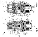
- Figure 1 and Figure 2 show a valve actuating device 1 according to the invention in longitudinal sectional views rotated by 90° with respect to one another.
- figure 3 shows the valve actuating device 1 in a three-dimensional oblique view.
- the valve actuating device 1 has a manual control element 2 with which a valve 3 arranged inside the valve actuating device 1 can be switched between a closed position and an open position.
- a control element 4 is arranged between the manual control element 2 and the valve 3 , which conveys an operating movement on the manual control element 2 to the valve 3 .
- control element 4 is connected to the valve 3 in such a way that the valve 3 can be switched with the control element 4 between the open position and the closed position.
- a compensating device 6 which transmits an actuation of the manual control element 2 to the control element 4 .
- the compensating device 6 has a receptacle 7 in which a plunger 8 is guided in a linearly sliding manner.
- This freedom of movement means that the control element 4 can be moved relative to the manual control element 2 .
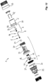
- a restoring element 9 is formed. This restoring element 9 develops a restoring force in order to move the control element 4 in the in Figure 4 and Figure 5 shown resting position in the receptacle 7 to keep.
- the restoring element 9 is arranged outside of the compensating device 6 and in particular outside of the receptacle 7 .
- the plunger 8, which is guided in the receptacle 7, is formed directly on the proximal end 10 of the control element 4.
- the receptacle 7 of the compensating device 6 is firmly connected to the manual control element 2 via a latching connection 11 .
- the longitudinal axis 12 of the valve-actuating device 1 defines a guide direction for the tappet, along which the tappet 8 is guided in the receptacle 7 is slidably guided.
- the receptacle 7 is provided with a ram removal opening 13 through which the ram 8 can be inserted laterally on the control element 4 .
- the valve 3 has a pressure chamber 14 which is connected to an inlet 16 of the valve 3 via a filling opening 15 .
- a cleaning pin 17 prevents the filling opening 15 from becoming clogged.
- the pressure chamber 14 is thus filled via the filling opening 15 .
- the pressure chamber 14 is connected to an outlet 19 of the valve 3 via an outlet opening 18 .
- the outlet 19 can be separated before the inlet 16 with the valve element 20 .
- the control element 4 is connected to a closure element 21 at the distal end 5 .
- the outlet opening 18 is formed in the valve element 20 in a manner corresponding to the closure element 21 , which—depending on the position of the manual control element 2 —can be closed or opened with the closure element 21 , that is to say it can be released.
- the closure element 21 can thus be used to control whether a pressure builds up in the pressure chamber 14 via the filling opening 15, which is the case when the discharge opening 18 is closed, or whether this built-up pressure is reduced again, in which the discharge opening 18 is released by the closure element 21 is.
- an opening diameter of the drain opening 18 is selected to be larger than an opening diameter of the filling opening 15 .
- valve element 20 When the pressure builds up, the valve element 20 is thus pressed against the outlet 19 in order to separate the inlet 16 from the outlet 19 .
- the pressure in the inlet 16 causes the valve element 20 to be pushed away from the inlet 16 and this inlet 16 to release.
- the valve 3 is then transferred to its open position.
- FIGS. 4 and 5 show an intermediate position in which the closure element 21 is already detached from the drain opening 18 in order to release it. However, the pressure in the pressure chamber 14 has not yet been reduced, so that the valve element 20 continues to close the outlet 19 .
- the control element 4 is arranged in the pressure chamber 14 .
- the pressure chamber 14 is sealed off from the manual control element 2 by a seal 22 .
- the seal 22 rests against a housing part 23 and is moved with the compensating device 6 .
- the pressure chamber 14 is closed off by an elastic membrane 24 .
- the membrane 24 carries the valve element 20 and the filling opening 15 formed on the valve element 20.
- the already mentioned housing part 23 and the membrane 24 thus delimit the pressure chamber 14.
- the membrane 24 is in this case clamped between the housing part 23 and a further housing part 25 which forms the inlet 16 and the outlet 19 .
- drain opening 18 and the drain 19 are arranged one behind the other in an extension of the control element 4 along the longitudinal axis 12, ie along the adjustment direction of the control element 4.
- valve element 20 The sealing of the outlet 19 against the inlet 16 by the valve element 20 is achieved in that the valve element 20 in the closed position according to Figure 1 and Figure 2 is pressed against a valve seat 26 on the outlet 19 by the pressure in the pressure chamber 14 .
- the restoring element 9 is designed as a helical spring and applies pressure to the control element 4 .
- the restoring element 9 is supported on the manual control element 2 via the receptacle 7 .
- the manual control element 2 is acted upon by a manual control element return spring 27 which is supported on the housing part 23 .
- the manual control element return spring 27 develops a greater force than the return element 4.
- Both the restoring element 4 and the manual control element restoring spring 27 are designed as helical springs which encompass the control element 4 and accommodate it.
- the compensating device 6 is also arranged at least partially in the manual control element return spring 27 .
- the manual control element 2 is hood-shaped and accommodates the compensating device 6 in its interior 28 .
- the manual control element 2 is held in a sleeve 29 which forms a stop on the manual control element 2 .
- the Figures 1 and 2 show the valve 3 in the closed position, in which the closure element 21 closes the drain opening 18 .
- This closing is already necessary for pressure build-up in the pressure chamber 14 when the valve element 20 has not yet arrived at the valve seat 26 .
- the manual control element 2 must already be in the lower position.
- pressing on the manual control element 2 first causes the plunger 8 to move in the receptacle 7 .
- the tension of the restoring element 9 causes the plunger 8 to move back to its stop in the receptacle 7 .
- the mobility of the plunger 8 in the receptacle 7 allows the manual control element 2 to be moved beyond an end of the adjustment path for the actuating element 4 that is predetermined by the closure element 21 .
- This is on a push-push locking mechanism advantageous, since it is then possible to go beyond the bottom (in relation to the push movement) dead center or stable point in order to retrieve the manual control element.
- the plunger 8 is designed as a cross-sectional thickening 30 on the proximal end 10 of the control element 4.
- this cross-sectional thickening 30 is connected in one piece to the control element 4 and is formed on it.
- a bistable adjusting mechanism 31 with a bracket 32 and a control groove 33 forms a push-push locking mechanism, for example a ballpoint pen mechanism or a cardioid mechanism, with which the manual control element 2 on the housing part 23 can be moved between an upper position ( Figure 4 and Figure 5 ) and a lower position ( Figure 1 and Figure 2 ) is adjustable by pressing along the longitudinal direction.
- a push-push locking mechanism for example a ballpoint pen mechanism or a cardioid mechanism
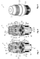
- FIGS. 7 to 12 show a further embodiment of a valve actuating device according to the invention.
- Components or functional units that are functionally and/or constructively identical or similar to components or functional units of the previous exemplary embodiment are denoted by the same reference symbols and are not described separately again.
- the remarks on the Figures 1 to 6 therefore apply to the Figures 7 to 12 accordingly.
- the embodiment according to Figures 7 to 12 differs from the previous exemplary embodiment in that the seal 22 is fixed in the housing part 23, so that the control element 4 is guided through the housing part 23 to the outside.
- the compensating device 6 is thus located behind the seal 22 and therefore outside the pressure chamber 14.
- the seal 22 rests against the control element 4 in this case.
- the embodiment according to Figures 7 to 12 also differs from the previous exemplary embodiment in that the restoring element 9 is supported on the housing part 23 . So that the manual control element 2 can move the control element 4 into the upper position that opens the drain opening 18 , the manual control element return spring 27 is designed to be stronger than the return element 9 .
- the control element 4 is arranged on the housing part 23 in a displaceable manner.
- FIGs 7 and 8 is shown again the closed position of the valve 3, while the Figures 10 and 11 show the open positions of the valve 3.
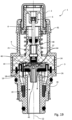
- FIGS. 13 to 16 show a further embodiment of a valve actuating device according to the invention. Again, components and functional units that are structurally and/or functionally similar or identical to components or functional units of the previous exemplary embodiments are denoted by the same reference symbols and are not described separately again. The remarks on the Figures 1 to 12 therefore apply to the Figures 13 to 16 accordingly.
- FIG. 13 to 16 initially shows in figure 13 the closed position of the valve 3, in which the closure element 21 closes the drain opening 18. A pressure is thus built up in the pressure chamber 14 via the filling opening 15 from the inlet 16 and presses the valve element 20 into the valve seat 26 .
- figure 14 shows an intermediate position in which the manual control element 2 has already moved to the upper position. This is done by pressing the manual control element 2, whereby the bistable adjustment mechanism 31 was transferred to the upper position.
- the drain opening 18 is larger than the filling opening 15 so that the pressure in the pressure chamber 14 is reduced via the drain opening 18 and the drain 19 .
- the embodiment according to Figures 13 to 16 differs from the previous exemplary embodiments in that an adjustment device 34 is additionally formed between the compensating device 6 and the manual control element 2, with which a maximum distance, i.e. a distance when the control element 4 is maximally extended from the receptacle 7, between the closure element 21 and the manual control element 2 is adjustable.
- a maximum distance i.e. a distance when the control element 4 is maximally extended from the receptacle 7, between the closure element 21 and the manual control element 2 is adjustable.
- the maximum distance between the valve seat 26 and the distal end 9 of the control element 4 i.e. a distance between the valve seat 26 on the one hand and the distal end 9 or the closure element 21 attached to it on the other hand, can be adjusted when the valve 3 is in the open position.
- An opening cross section on the valve seat 26 in the open position can thus be changed.
- a movement thread 35 is formed on the manual control element 2 is, with which a rotary movement of the manual control element 2 can be converted into a displacement movement along the longitudinal axis 12 of a sleeve-shaped intermediate part.
- the hand-held operating element 2 is therefore not only displaceable along the longitudinal axis 12 but is also set up to rotate or pivot about the longitudinal axis 12 .
- figure 16 shows one opposite figure 15 shifted position of the intermediate part 36.
- This displacement changes a distance between the receptacle 7 of the compensating device 6 and the manual control element 2 .
- the manual control element 2 is arranged to be adjustable together with the control element 4 by means of an adjustment device 34, for example a movement thread 35, along the longitudinal axis 12 in order to bring the distal end 9 closer to the valve seat 26 in the open position of the valve 3 or further to remove from this.
- an adjustment device 34 for example a movement thread 35
- a support spring 37 supports in the Figures 13 to 16 the extension of the operating element 2 from the intermediate part 36, which is controlled by the motion thread 35.
- FIGS 17 to 19 show a further exemplary embodiment of a valve actuating device 1 according to the invention.
- components and functional units which are structurally and/or functionally similar or identical to components or functional units of the preceding exemplary embodiments are denoted by the same reference symbols and are not described separately again.
- the remarks on the Figures 1 to 16 therefore apply to the Figures 17 to 19 accordingly.
- the valve actuating device 1 differs from the preceding exemplary embodiments in that a cross-sectional area at the outflow opening 18, which can be covered by the closure element 21, is enlarged.
- the cross-sectional area is so large here that the closure element 21 with the control element 4 is transferred into the closed position by an internal pressure in the pressure chamber 14 .
- cross-sectional area that can be covered by the closure element 21 at the outlet opening 18 is larger than a cross-sectional area of the control element 4 at its exit from the pressure chamber 14, i.e. in the area of a passage opening 40.
- pilot valve seat 44 which can be closed and released with the closure element 21 and forms a pilot valve 46 with it.
- the restoring element 9 can be dimensioned with a low spring force.
- the manual control element return spring 27 also does not have to be dimensioned with a large spring force. In this way, easy switching behavior can be achieved.
- the drain opening 18 describes a constriction 45 in the direction of flow behind the pilot valve seat 44, which can be funnel-shaped, for example, and which leads to a very small inner diameter and/or inner cross-section of the drain opening 18 at its narrowest point.
- valve operating device 1 after Figures 17 to 19 differs further from the previous exemplary embodiments in that a pipe socket 38 is attached to the outlet opening 18 . This protrudes into the outlet 19 in all switching positions, i.e. also when the valve 3 is open, and prevents a backflow from a main flow path 39 of the open valve 3 to or into the outlet opening 18.
- the pipe socket 38 generally has an outer diameter which is smaller than an inner diameter of the valve seat 26 or the outlet 19, for example at most half as large.
- the lifting height 43 can be given by a dimension of the pressure chamber 14 or in some other way, for example by stops for the valve element 20.
- valve-actuating device 1 it is proposed to form a compensating device 6 between a manual operating element 2 and a control element 4, with which a valve 3 can be adjusted between an open position and a closed position which the control element 4 can be moved against a restoring force of a restoring element 9 relative to the manual control element 2 and towards or away from it, with the restoring element 9 being arranged outside of the compensating device 6 and/or a plunger 8 being arranged on the control element 4 and in a receptacle 7 of the compensating device 6 is guided, with an adjustment device 34 being additionally or alternatively formed, with which the control element 4 can be removed from the manual control element 2 or moved towards it.
Landscapes
- Engineering & Computer Science (AREA)
- General Engineering & Computer Science (AREA)
- Mechanical Engineering (AREA)
- Mechanically-Actuated Valves (AREA)
- Preventing Unauthorised Actuation Of Valves (AREA)
- Fluid-Driven Valves (AREA)
- Sliding Valves (AREA)
Claims (23)
- Dispositif d'actionnement de soupape (1), comprenant un élément à commande manuelle (2) et une soupape (3) qui peut être actionnée par le biais de l'élément à commande manuelle (2), dans lequel un élément de commande (4) est en liaison fonctionnelle avec l'élément à commande manuelle (2), dans lequel la soupape (3) peut être actionnée avec une extrémité distale (5) de l'élément de commande (4) et, dans la liaison fonctionnelle, est disposé entre l'élément de commande (4) et l'élément à commande manuelle (2) un moyen de compensation (6) qui présente un poussoir (8) guidé de manière mobile dans un logement (7) et autorise un mouvement relatif de l'élément à commande manuelle (2) contre l'élément de commande (4), et dans lequel un élément de rappel (9) est présent et oppose une force de rappel au mouvement relatif, caractérisé en ce que,- l'élément de rappel (9) est disposé à l'extérieur du moyen de compensation (6) et- en ce que le poussoir (8) est configuré à une extrémité proximale (10) de l'élément de commande (4) et- en ce que le logement (7) du moyen de compensation (6) est disposé de manière fixe sur l'élément à commande manuelle (2).
- Dispositif d'actionnement de soupape (1) selon l'une des revendications précédentes, caractérisé en ce que l'élément de rappel (9) sollicite l'élément de commande (4).
- Dispositif d'actionnement de soupape (1) selon l'une des revendications précédentes, caractérisé en ce que le logement (7) présente une ouverture de prélèvement de poussoir (13) transversalement à une direction de guidage de poussoir et ouverte latéralement et/ou en ce que le logement (7) forme une butée contre laquelle l'élément de rappel (9) pousse le poussoir (8) dans une position de repos.
- Dispositif d'actionnement de soupape (1) selon l'une des revendications précédentes, dans lequel un moyen d'ajustement (34) est configuré, avec lequel une distance maximale entre un siège de soupape (26) de la soupape (3) et l'extrémité distale (5) de l'élément de commande (4) peut être ajustée, caractérisé en ce qu'à l'aide du moyen d'ajustement (34) une distance entre le logement (7) du moyen de compensation (6) et l'élément à commande manuelle (2) peut être modifiée.
- Dispositif d'actionnement de soupape (1) selon la revendication 4, caractérisé en ce que le moyen d'ajustement (34) est disposé entre le moyen de compensation (6) et l'élément à commande manuelle (2) et est configuré pour un ajustement d'une distance entre le moyen de compensation (6) et l'élément à commande manuelle (2) et/ou en ce que le moyen d'ajustement (34) présente un filetage de déplacement (35) et/ou un ressort de soutien (37), avec lequel un mouvement d'entraînement peut être soutenu.
- Dispositif d'actionnement de soupape (1) selon l'une des revendications précédentes, caractérisé en ce que l'élément à commande manuelle (2) est disposé de manière mobile.
- Dispositif d'actionnement de soupape (1) selon l'une des revendications précédentes, caractérisé en ce que la soupape (3) présente une chambre de pression (14) qui est reliée, par le biais d'une ouverture de chargement (15), à une alimentation (16) de la soupape (3) et, par le biais d'une ouverture d'évacuation (18), à une évacuation (19) de la soupape (3), dans lequel un élément de soupape (20) de la soupape (3) séparant l'évacuation (19) de l'alimentation (16) peut être sollicité avec la chambre de pression (14) et dans lequel l'ouverture d'évacuation (18) peut être ouverte et fermée avec un élément de fermeture (21).
- Dispositif d'actionnement de soupape (1) selon l'une des revendications précédentes, caractérisé en ce que la ou une chambre de pression (14) de la soupape (3) est rendue étanche par rapport à l'élément à commande manuelle (2) par le biais d'un joint d'étanchéité (22).
- Dispositif d'actionnement de soupape (1) selon l'une des revendications précédentes, caractérisé en ce que l'élément de soupape (20) est suspendu à une ouverture de chargement (15) de la ou une membrane élastique (24) portant la chambre de pression (14).
- Dispositif d'actionnement de soupape (1) selon l'une des revendications précédentes, caractérisé en ce que la ou une chambre de pression (14) de la soupape (3) est délimitée par la ou une partie de boîtier (23) et la ou une membrane (24) fixée à la partie de boîtier (23).
- Dispositif d'actionnement de soupape (1) selon l'une des revendications précédentes, caractérisé en ce que la ou une ouverture d'évacuation (18) de la ou d'une chambre de pression (14) de la soupape (3) est disposée dans un prolongement de l'élément de commande (4) et/ou en ce que la ou une évacuation (19) est disposée dans un prolongement de l'ouverture d'évacuation (18).
- Dispositif d'actionnement de soupape (1) selon l'une des revendications précédentes, caractérisé en ce que la ou une alimentation (16) est séparée de la ou une évacuation (19) par le ou un siège de soupape (26) annulaire.
- Dispositif d'actionnement de soupape (1) selon l'une des revendications précédentes, caractérisé en ce que l'élément de rappel (9) sollicite sous pression l'élément de commande (4).
- Dispositif d'actionnement de soupape (1) selon l'une des revendications précédentes, caractérisé en ce que l'élément de rappel (9) est appuyé sur la ou une partie de boîtier (23) et/ou sur l'élément à commande manuelle (2).
- Dispositif d'actionnement de soupape (1) selon l'une des revendications précédentes, caractérisé en ce que l'élément à commande manuelle (2) est sollicité par un ressort de rappel (27) de l'élément à commande manuelle.
- Dispositif d'actionnement de soupape (1) selon l'une des revendications précédentes, caractérisé en ce que l'élément à commande manuelle (2) reçoit le moyen de compensation (6) et l'élément de commande (4), ou empiète sur ceux-là, au moins partiellement à la manière d'une coiffe.
- Dispositif d'actionnement de soupape (1) selon l'une des revendications précédentes, caractérisé en ce que l'élément à commande manuelle (2) peut être ajusté au-delà d'un point de butée de l'élément de commande (4).
- Dispositif d'actionnement de soupape (1) selon l'une des revendications précédentes, caractérisé en ce que l'élément de commande (4) est configuré sous la forme d'une barre et/ou présente, à une extrémité opposée de la soupape (3), un épaississement de section transversale (30) et/ou en ce que l'élément de commande (4) est monté mobile et disposé sur la ou une partie de boîtier (23).
- Dispositif d'actionnement de soupape (1) selon l'une des revendications précédentes, caractérisé en ce que le logement (7) et/ou l'élément à commande manuelle (2) sont reliés à un mécanisme de réglage bistable (31).
- Dispositif d'actionnement de soupape (1) selon l'une des revendications précédentes, dans lequel la soupape (3) présente une chambre de pression (14) qui est reliée, par le biais d'une ouverture de chargement (15), à une alimentation (16) de la soupape (3) et, par le biais d'une ouverture d'évacuation (18), à une évacuation (19) de la soupape (3), dans lequel un élément de soupape (20) de la soupape (3) séparant l'évacuation (19) de l'alimentation (16) peut être sollicité avec la chambre de pression (14) et dans lequel l'ouverture d'évacuation (18) peut être ouverte et fermée avec un élément de fermeture (21), caractérisé en ce qu'une surface en coupe transversale qui peut être recouverte de l'élément de fermeture (21) est au niveau de l'ouverture d'évacuation (18) plus grande qu'une surface en coupe transversale de l'élément de commande (4) au niveau de sa sortie de la chambre de pression (14), et en ce que la chambre de pression (14) de la soupape (3) peut être rendue étanche vis-à-vis de l'élément à commande manuelle (2) par le biais d'un joint d'étanchéité (22) situé au niveau de l'élément de commande (4).
- Dispositif d'actionnement de soupape (1) selon la revendication 20, caractérisé en ce qu'au niveau de l'élément de soupape (20), est configuré un siège de soupape pilote (44), qui permet de fermer et libérer l'élément de fermeture (21), et en ce que l'ouverture d'évacuation (18) forme un rétrécissement (45) en aval du siège de soupape pilote (44) dans la direction d'écoulement.
- Dispositif d'actionnement de soupape (1) selon la revendication 20, caractérisé en ce qu'au niveau de l'ouverture d'évacuation (18), est appliqué un manchon tubulaire (38), lequel fait saillie dans l'évacuation (19) même lorsque la soupape (3) est ouverte et empêche un courant de retour provenant de la trajectoire d'écoulement principal (39) de la soupape (3) au niveau de l'ouverture d'évacuation (18) de sorte qu'une résistance contre une fermeture de la soupape (3), qui est développée par l'écoulement principal, puisse être réduite, dans lequel le manchon tubulaire (38) est fourni sous la forme d'un manchon tubulaire de redressement qui éloigne l'écoulement principal de l'ouverture d'évacuation (18) et dans lequel l'élément de rappel (9) sollicite l'élément de commande (4).
- Dispositif d'actionnement de soupape (1) selon la revendication 22, caractérisé en ce qu'une longueur (42), avec laquelle l'élément de soupape (20) fait saillie dans l'évacuation (19) avec le manchon tubulaire (38) dans la position de fermeture de la soupape (3), représente au moins 1,5 fois une hauteur de course (43) de l'élément de soupape (20).
Priority Applications (8)
| Application Number | Priority Date | Filing Date | Title |
|---|---|---|---|
| EP19156759.3A EP3514426B1 (fr) | 2016-02-22 | 2017-02-21 | Dispositif d'actionnement de soupape |
| EP19156761.9A EP3521672B1 (fr) | 2016-02-22 | 2017-02-21 | Dispositif d'actionnement de soupape |
| PL17707168T PL3420258T3 (pl) | 2016-02-22 | 2017-02-21 | Urządzenie do sterowania zaworem |
| PL19156759T PL3514426T3 (pl) | 2016-02-22 | 2017-02-21 | Urządzenie do sterowania zaworem |
| EP19156764.3A EP3514427A1 (fr) | 2016-02-22 | 2017-02-21 | Dispositif d'actionnement de soupape |
| EP19156756.9A EP3514425B1 (fr) | 2016-02-22 | 2017-02-21 | Dispositif d'actionnement de soupape |
| EP23168983.7A EP4219990A3 (fr) | 2016-02-22 | 2017-02-21 | Dispositif d'actionnement de soupape |
| PL19156756T PL3514425T3 (pl) | 2016-02-22 | 2017-02-21 | Urządzenie do sterowania zaworem |
Applications Claiming Priority (2)
| Application Number | Priority Date | Filing Date | Title |
|---|---|---|---|
| DE202016001106.6U DE202016001106U1 (de) | 2016-02-22 | 2016-02-22 | Ventilbetätigungsvorrichtung |
| PCT/EP2017/000242 WO2017144169A1 (fr) | 2016-02-22 | 2017-02-21 | Dispositif d'actionnement de soupape |
Related Child Applications (10)
| Application Number | Title | Priority Date | Filing Date |
|---|---|---|---|
| EP19156764.3A Division EP3514427A1 (fr) | 2016-02-22 | 2017-02-21 | Dispositif d'actionnement de soupape |
| EP19156764.3A Division-Into EP3514427A1 (fr) | 2016-02-22 | 2017-02-21 | Dispositif d'actionnement de soupape |
| EP23168983.7A Division EP4219990A3 (fr) | 2016-02-22 | 2017-02-21 | Dispositif d'actionnement de soupape |
| EP23168983.7A Division-Into EP4219990A3 (fr) | 2016-02-22 | 2017-02-21 | Dispositif d'actionnement de soupape |
| EP19156761.9A Division EP3521672B1 (fr) | 2016-02-22 | 2017-02-21 | Dispositif d'actionnement de soupape |
| EP19156761.9A Division-Into EP3521672B1 (fr) | 2016-02-22 | 2017-02-21 | Dispositif d'actionnement de soupape |
| EP19156756.9A Division EP3514425B1 (fr) | 2016-02-22 | 2017-02-21 | Dispositif d'actionnement de soupape |
| EP19156756.9A Division-Into EP3514425B1 (fr) | 2016-02-22 | 2017-02-21 | Dispositif d'actionnement de soupape |
| EP19156759.3A Division EP3514426B1 (fr) | 2016-02-22 | 2017-02-21 | Dispositif d'actionnement de soupape |
| EP19156759.3A Division-Into EP3514426B1 (fr) | 2016-02-22 | 2017-02-21 | Dispositif d'actionnement de soupape |
Publications (3)
| Publication Number | Publication Date |
|---|---|
| EP3420258A1 EP3420258A1 (fr) | 2019-01-02 |
| EP3420258B1 EP3420258B1 (fr) | 2020-02-12 |
| EP3420258B2 true EP3420258B2 (fr) | 2023-06-28 |
Family
ID=58162499
Family Applications (6)
| Application Number | Title | Priority Date | Filing Date |
|---|---|---|---|
| EP19156756.9A Active EP3514425B1 (fr) | 2016-02-22 | 2017-02-21 | Dispositif d'actionnement de soupape |
| EP19156764.3A Pending EP3514427A1 (fr) | 2016-02-22 | 2017-02-21 | Dispositif d'actionnement de soupape |
| EP19156759.3A Active EP3514426B1 (fr) | 2016-02-22 | 2017-02-21 | Dispositif d'actionnement de soupape |
| EP17707168.5A Active EP3420258B2 (fr) | 2016-02-22 | 2017-02-21 | Dispositif d'actionnement de soupape |
| EP19156761.9A Active EP3521672B1 (fr) | 2016-02-22 | 2017-02-21 | Dispositif d'actionnement de soupape |
| EP23168983.7A Pending EP4219990A3 (fr) | 2016-02-22 | 2017-02-21 | Dispositif d'actionnement de soupape |
Family Applications Before (3)
| Application Number | Title | Priority Date | Filing Date |
|---|---|---|---|
| EP19156756.9A Active EP3514425B1 (fr) | 2016-02-22 | 2017-02-21 | Dispositif d'actionnement de soupape |
| EP19156764.3A Pending EP3514427A1 (fr) | 2016-02-22 | 2017-02-21 | Dispositif d'actionnement de soupape |
| EP19156759.3A Active EP3514426B1 (fr) | 2016-02-22 | 2017-02-21 | Dispositif d'actionnement de soupape |
Family Applications After (2)
| Application Number | Title | Priority Date | Filing Date |
|---|---|---|---|
| EP19156761.9A Active EP3521672B1 (fr) | 2016-02-22 | 2017-02-21 | Dispositif d'actionnement de soupape |
| EP23168983.7A Pending EP4219990A3 (fr) | 2016-02-22 | 2017-02-21 | Dispositif d'actionnement de soupape |
Country Status (10)
| Country | Link |
|---|---|
| US (1) | US11408534B2 (fr) |
| EP (6) | EP3514425B1 (fr) |
| JP (1) | JP6743163B2 (fr) |
| CN (1) | CN108603616B (fr) |
| BR (1) | BR112018014630B1 (fr) |
| DE (2) | DE202016001106U1 (fr) |
| ES (3) | ES2786570T3 (fr) |
| MX (1) | MX2018009373A (fr) |
| PL (3) | PL3514425T3 (fr) |
| WO (1) | WO2017144169A1 (fr) |
Families Citing this family (13)
| Publication number | Priority date | Publication date | Assignee | Title |
|---|---|---|---|---|
| DE202017103194U1 (de) | 2017-05-26 | 2018-08-28 | Neoperl Gmbh | Sanitärventil |
| DE102017115191A1 (de) * | 2017-07-06 | 2019-01-10 | A. u. K. Müller GmbH & Co. KG | Ventil, insbesondere Servoventil |
| DE102017222196A1 (de) | 2017-12-07 | 2019-06-13 | Hansgrohe Se | Ventilbetätigungsvorrichtung und Sanitärventil |
| DE202018102401U1 (de) * | 2018-04-30 | 2019-07-31 | Neoperl Gmbh | Ventilbetätigungsvorrichtung |
| DE202018103806U1 (de) * | 2018-07-03 | 2019-10-14 | Neoperl Gmbh | Ventil, Armatur und Verwendung eines Ventils |
| DE102019202273A1 (de) * | 2019-02-20 | 2020-08-20 | Hansgrohe Se | Umstellventilvorrichtung |
| DE202019101264U1 (de) * | 2019-03-06 | 2020-06-09 | Neoperl Gmbh | Ventilanordnung |
| DE102019003301A1 (de) * | 2019-05-10 | 2020-11-12 | Grohe Ag | Einhebel-Kartusche für eine Sanitärarmatur |
| EP4018113A1 (fr) * | 2019-08-20 | 2022-06-29 | Rotarex S.A. | Soupape de bouteille à gaz dotée d'une poignée d'actionnement s'étendant radialement |
| DE202019105003U1 (de) * | 2019-09-10 | 2020-12-14 | Neoperl Gmbh | Betätigungsvorrichtung und Verwendung einer Betätigungsvorrichtung |
| GB2595462B (en) * | 2020-05-26 | 2022-08-24 | Kohler Mira Ltd | Ablutionary fitting control |
| CN113932015A (zh) * | 2020-07-14 | 2022-01-14 | 厦门松霖科技股份有限公司 | 一种带有流量调节的出水阀和出水龙头 |
| DE102021129459B4 (de) | 2021-11-11 | 2023-07-06 | Neoperl Gmbh | Sanitärventil |
Citations (42)
| Publication number | Priority date | Publication date | Assignee | Title |
|---|---|---|---|---|
| FR2223618A1 (fr) † | 1973-04-02 | 1974-10-25 | Melnikova Alexandra | |
| GB2103391A (en) † | 1981-07-31 | 1983-02-16 | Peglers Ltd | Servo operated fluid flow taps and valves |
| JPS5868558A (ja) † | 1981-10-16 | 1983-04-23 | Hitachi Ltd | 蒸発圧力制御弁 |
| DE3927611A1 (de) † | 1989-03-17 | 1990-09-20 | Schulze Michael | Betaetigung eines membranventils mittels eines dauermagneten |
| JPH0464783A (ja) † | 1990-07-02 | 1992-02-28 | Matsushita Electric Ind Co Ltd | 止水・流量調節装置 |
| DE9413654U1 (de) † | 1993-08-10 | 1994-11-10 | Interelektrik Ges.M.B.H. & Co. Kg, Villach | Bistabiles Magnetventil |
| JP2001098596A (ja) † | 1999-09-29 | 2001-04-10 | Inax Corp | 吐水装置 |
| JP2001095709A (ja) † | 1999-09-28 | 2001-04-10 | Inax Corp | 吐水装置 |
| JP2001095710A (ja) † | 1999-09-29 | 2001-04-10 | Inax Corp | 吐水装置 |
| DE10200979A1 (de) † | 2002-01-12 | 2003-08-07 | Danfoss As | Ventilanordnung zum Einsetzen in Vakuumanlagen |
| US6634618B2 (en) † | 2000-05-24 | 2003-10-21 | Kil Yong Jang | Water saving automatic valve |
| US20040135013A1 (en) † | 2001-06-04 | 2004-07-15 | L.R. Nelson Corporation | One touch actuated valve |
| JP2005155797A (ja) † | 2003-11-26 | 2005-06-16 | Toto Ltd | 水栓装置 |
| JP2005163990A (ja) † | 2003-12-05 | 2005-06-23 | Toto Ltd | 水栓装置 |
| JP2005264459A (ja) † | 2004-03-16 | 2005-09-29 | Toto Ltd | 開閉弁装置及びそれを備えた水栓装置 |
| JP2005264979A (ja) † | 2004-03-16 | 2005-09-29 | Toto Ltd | 開閉弁装置及びそれを備えた水栓装置 |
| JP3743006B2 (ja) † | 2004-06-09 | 2006-02-08 | 東陶機器株式会社 | 開閉弁装置及びそれを備えた水栓装置 |
| JP2006308021A (ja) † | 2005-04-28 | 2006-11-09 | Toto Ltd | 開閉弁装置 |
| JP3132061U (ja) † | 2007-03-13 | 2007-05-31 | Nok株式会社 | 押ボタン水栓 |
| CN101012889A (zh) † | 2007-02-13 | 2007-08-08 | 万若(北京)环境工程技术有限公司 | 用于污水输送的膜片式负压阀 |
| EP1903267A1 (fr) † | 2005-07-12 | 2008-03-26 | Inax Corporation | Dispositif de soupape de régulation du débit et d' évacuation/d' arrêt de l' eau de type pilote |
| JP2012145144A (ja) † | 2011-01-07 | 2012-08-02 | Toto Ltd | 吐水装置 |
| CN102661435A (zh) † | 2012-05-18 | 2012-09-12 | 全龙浩 | 双开自动喷淋阀 |
| EP2530365A1 (fr) † | 2011-05-31 | 2012-12-05 | Hansgrohe SE | Garniture de soupape pour une armature sanitaire |
| US20130200282A1 (en) † | 2012-02-07 | 2013-08-08 | Tianbaili new technology development Co., Ltd. | Double-switched automatic sprinkler valve |
| KR20130090635A (ko) † | 2012-02-06 | 2013-08-14 | 윤용호 | 솔레노이드 래칭밸브의 개폐상태 감지 스위치 |
| CN203297709U (zh) † | 2013-06-09 | 2013-11-20 | 福建汇才实业发展有限公司 | 底进侧出磁力式延时冲洗阀阀芯 |
| DE102012221043A1 (de) † | 2012-11-19 | 2014-05-22 | Hansgrohe Se | Sanitärventil |
| DE102012221047A1 (de) † | 2012-11-19 | 2014-05-22 | Hansgrohe Se | Ventiloberteil für eine Sanitärarmatur |
| CN203656296U (zh) † | 2013-12-31 | 2014-06-18 | 厦门松霖科技有限公司 | 一种按压开闭调流量阀 |
| GB2509796A (en) † | 2012-09-29 | 2014-07-16 | Quanduo Hou | Water heater valve |
| WO2014164906A1 (fr) † | 2013-03-11 | 2014-10-09 | Pentair Residential Filtration, Llc | Manostat mécanique |
| CN203948677U (zh) † | 2014-06-06 | 2014-11-19 | 开平吉星卫浴实业有限公司 | 一种按钮式分水器 |
| EP2865929A1 (fr) † | 2013-10-25 | 2015-04-29 | Fabrizio Nobili | Dispositif de réglage de l'eau dans une baignoire ou de douche ou évier de cuisine |
| EP2865928A1 (fr) † | 2013-10-25 | 2015-04-29 | Fabrizio Nobili | Vanne |
| EP2868953A1 (fr) † | 2013-10-31 | 2015-05-06 | A. u. K. Müller GmbH & Co. KG | Soupape |
| JP5711977B2 (ja) † | 2011-01-07 | 2015-05-07 | Toto株式会社 | 吐水装置 |
| CN104896106A (zh) † | 2015-05-08 | 2015-09-09 | 余姚市普润净水设备有限公司 | 用于组合阀的钢管 |
| CN104948775A (zh) † | 2015-06-12 | 2015-09-30 | 鹤山市天健卫浴有限公司 | 水温稳定按压式控制阀 |
| CN104948817A (zh) † | 2015-06-12 | 2015-09-30 | 鹤山市天健卫浴有限公司 | 流量可调按压式控制阀 |
| CN104948777A (zh) † | 2015-06-12 | 2015-09-30 | 鹤山市天健卫浴有限公司 | 按压式控制可调阀 |
| DE202014007070U1 (de) † | 2014-09-04 | 2015-12-08 | Neoperl Gmbh | Absperrventil |
Family Cites Families (25)
| Publication number | Priority date | Publication date | Assignee | Title |
|---|---|---|---|---|
| US1146723A (en) * | 1914-07-03 | 1915-07-13 | Perry Losh | Combined stop and relief valve. |
| US2946551A (en) * | 1957-06-03 | 1960-07-26 | American Radiator & Standard | Detachable mounting for solenoid coil |
| US3768771A (en) * | 1971-11-12 | 1973-10-30 | Gen Electric | Fluid control valve with improved diaphragm |
| JPS52100233U (fr) * | 1976-01-28 | 1977-07-29 | ||
| JPS5497826A (en) * | 1978-01-18 | 1979-08-02 | Toyooki Kogyo Kk | Flow control valve |
| US4293118A (en) * | 1979-11-26 | 1981-10-06 | American Standard Inc. | Multi-function operator for control valve device |
| US4361167A (en) * | 1979-11-29 | 1982-11-30 | Ogontz Controls Company | Snap-acting drain valve |
| FR2481404A1 (fr) | 1980-04-24 | 1981-10-30 | Fonderie Soc Gen De | Robinet sanitaire comportant un organe de marche-arret a deux positions stables |
| JPS5915115A (ja) | 1982-07-15 | 1984-01-26 | Takuo Mochizuki | 軟弱又は水中地盤等の固定化方法 |
| JPS5915115U (ja) * | 1982-07-20 | 1984-01-30 | リンナイ株式会社 | 手押型ガス開閉装置 |
| DE8704797U1 (de) | 1987-03-31 | 1987-07-23 | Hubert Schell Gmbh & Co Kg, 5960 Olpe | Druckspüler |
| JP3020501U (ja) | 1995-07-14 | 1996-02-02 | 株式会社ベンカン | 流量調整機構付自動弁 |
| DE29820432U1 (de) * | 1998-11-16 | 1999-01-14 | Hüwel, Ralf, 48477 Hörstel | Niveau- oder druckgesteuerte, rein mechanische Ventileinheit |
| US6588724B2 (en) * | 2001-08-15 | 2003-07-08 | Jetec Company | On-off valves for high pressure fluids |
| JP3632976B2 (ja) | 2002-08-30 | 2005-03-30 | 東陶機器株式会社 | 開閉弁装置 |
| DE202006001009U1 (de) * | 2006-01-24 | 2007-06-06 | A. u. K. Müller GmbH & Co KG | Eigenmediumbetätigtes durch einen Magnetanker gesteuertes Servoventil |
| DE102008018639A1 (de) * | 2008-04-11 | 2009-10-22 | Otto Egelhof Gmbh & Co. Kg | Thermostatische Regeleinrichtung |
| DE202011101289U1 (de) | 2011-05-31 | 2012-09-07 | Neoperl Gmbh | Umstellventil |
| CN203230877U (zh) * | 2013-01-29 | 2013-10-09 | 辉煌水暖集团有限公司 | 一种阀组件及阀组件的膜片 |
| CN204201125U (zh) * | 2014-09-26 | 2015-03-11 | 鹤山市天健卫浴有限公司 | 内腔封闭阀芯 |
| CN204201170U (zh) * | 2014-09-26 | 2015-03-11 | 鹤山市天健卫浴有限公司 | 密封阀芯 |
| CN205479393U (zh) * | 2016-01-12 | 2016-08-17 | 福建西河卫浴科技有限公司 | 一种按压式开关阀 |
| DE102016001975A1 (de) | 2016-02-22 | 2017-08-24 | Neoperl Gmbh | Ventilbetätigungsvorrichtung |
| CN106051208B (zh) * | 2016-07-27 | 2019-11-29 | 路达(厦门)工业有限公司 | 切换阀单元、流体开关和流体开关的套件 |
| DE202021100840U1 (de) * | 2021-02-19 | 2022-05-27 | Neoperl Gmbh | Sanitärventil |
-
2016
- 2016-02-22 DE DE202016001106.6U patent/DE202016001106U1/de active Active
- 2016-05-24 DE DE102016006388.2A patent/DE102016006388B4/de active Active
-
2017
- 2017-02-21 CN CN201780009448.1A patent/CN108603616B/zh active Active
- 2017-02-21 ES ES17707168T patent/ES2786570T3/es active Active
- 2017-02-21 PL PL19156756T patent/PL3514425T3/pl unknown
- 2017-02-21 PL PL17707168T patent/PL3420258T3/pl unknown
- 2017-02-21 EP EP19156756.9A patent/EP3514425B1/fr active Active
- 2017-02-21 EP EP19156764.3A patent/EP3514427A1/fr active Pending
- 2017-02-21 ES ES19156759T patent/ES2797975T3/es active Active
- 2017-02-21 ES ES19156756T patent/ES2797973T3/es active Active
- 2017-02-21 PL PL19156759T patent/PL3514426T3/pl unknown
- 2017-02-21 MX MX2018009373A patent/MX2018009373A/es unknown
- 2017-02-21 WO PCT/EP2017/000242 patent/WO2017144169A1/fr active Application Filing
- 2017-02-21 EP EP19156759.3A patent/EP3514426B1/fr active Active
- 2017-02-21 JP JP2018544251A patent/JP6743163B2/ja active Active
- 2017-02-21 EP EP17707168.5A patent/EP3420258B2/fr active Active
- 2017-02-21 US US16/074,321 patent/US11408534B2/en active Active
- 2017-02-21 EP EP19156761.9A patent/EP3521672B1/fr active Active
- 2017-02-21 EP EP23168983.7A patent/EP4219990A3/fr active Pending
- 2017-02-21 BR BR112018014630-7A patent/BR112018014630B1/pt active IP Right Grant
Patent Citations (43)
| Publication number | Priority date | Publication date | Assignee | Title |
|---|---|---|---|---|
| FR2223618A1 (fr) † | 1973-04-02 | 1974-10-25 | Melnikova Alexandra | |
| GB2103391A (en) † | 1981-07-31 | 1983-02-16 | Peglers Ltd | Servo operated fluid flow taps and valves |
| JPS5868558A (ja) † | 1981-10-16 | 1983-04-23 | Hitachi Ltd | 蒸発圧力制御弁 |
| DE3927611A1 (de) † | 1989-03-17 | 1990-09-20 | Schulze Michael | Betaetigung eines membranventils mittels eines dauermagneten |
| JPH0464783A (ja) † | 1990-07-02 | 1992-02-28 | Matsushita Electric Ind Co Ltd | 止水・流量調節装置 |
| DE9413654U1 (de) † | 1993-08-10 | 1994-11-10 | Interelektrik Ges.M.B.H. & Co. Kg, Villach | Bistabiles Magnetventil |
| JP2001095709A (ja) † | 1999-09-28 | 2001-04-10 | Inax Corp | 吐水装置 |
| JP2001095710A (ja) † | 1999-09-29 | 2001-04-10 | Inax Corp | 吐水装置 |
| JP2001098596A (ja) † | 1999-09-29 | 2001-04-10 | Inax Corp | 吐水装置 |
| US6634618B2 (en) † | 2000-05-24 | 2003-10-21 | Kil Yong Jang | Water saving automatic valve |
| US20040135013A1 (en) † | 2001-06-04 | 2004-07-15 | L.R. Nelson Corporation | One touch actuated valve |
| DE10200979A1 (de) † | 2002-01-12 | 2003-08-07 | Danfoss As | Ventilanordnung zum Einsetzen in Vakuumanlagen |
| JP2005155797A (ja) † | 2003-11-26 | 2005-06-16 | Toto Ltd | 水栓装置 |
| JP2005163990A (ja) † | 2003-12-05 | 2005-06-23 | Toto Ltd | 水栓装置 |
| JP2005264459A (ja) † | 2004-03-16 | 2005-09-29 | Toto Ltd | 開閉弁装置及びそれを備えた水栓装置 |
| JP2005264979A (ja) † | 2004-03-16 | 2005-09-29 | Toto Ltd | 開閉弁装置及びそれを備えた水栓装置 |
| JP3743006B2 (ja) † | 2004-06-09 | 2006-02-08 | 東陶機器株式会社 | 開閉弁装置及びそれを備えた水栓装置 |
| JP2006308021A (ja) † | 2005-04-28 | 2006-11-09 | Toto Ltd | 開閉弁装置 |
| EP1903267A1 (fr) † | 2005-07-12 | 2008-03-26 | Inax Corporation | Dispositif de soupape de régulation du débit et d' évacuation/d' arrêt de l' eau de type pilote |
| CN101012889A (zh) † | 2007-02-13 | 2007-08-08 | 万若(北京)环境工程技术有限公司 | 用于污水输送的膜片式负压阀 |
| JP3132061U (ja) † | 2007-03-13 | 2007-05-31 | Nok株式会社 | 押ボタン水栓 |
| JP2012145144A (ja) † | 2011-01-07 | 2012-08-02 | Toto Ltd | 吐水装置 |
| JP5711977B2 (ja) † | 2011-01-07 | 2015-05-07 | Toto株式会社 | 吐水装置 |
| EP2530365A1 (fr) † | 2011-05-31 | 2012-12-05 | Hansgrohe SE | Garniture de soupape pour une armature sanitaire |
| CN202927053U (zh) † | 2011-05-31 | 2013-05-08 | 汉斯格罗欧洲公司 | 用于卫生配件的阀插入件 |
| KR20130090635A (ko) † | 2012-02-06 | 2013-08-14 | 윤용호 | 솔레노이드 래칭밸브의 개폐상태 감지 스위치 |
| US20130200282A1 (en) † | 2012-02-07 | 2013-08-08 | Tianbaili new technology development Co., Ltd. | Double-switched automatic sprinkler valve |
| CN102661435A (zh) † | 2012-05-18 | 2012-09-12 | 全龙浩 | 双开自动喷淋阀 |
| GB2509796A (en) † | 2012-09-29 | 2014-07-16 | Quanduo Hou | Water heater valve |
| DE102012221043A1 (de) † | 2012-11-19 | 2014-05-22 | Hansgrohe Se | Sanitärventil |
| DE102012221047A1 (de) † | 2012-11-19 | 2014-05-22 | Hansgrohe Se | Ventiloberteil für eine Sanitärarmatur |
| WO2014164906A1 (fr) † | 2013-03-11 | 2014-10-09 | Pentair Residential Filtration, Llc | Manostat mécanique |
| CN203297709U (zh) † | 2013-06-09 | 2013-11-20 | 福建汇才实业发展有限公司 | 底进侧出磁力式延时冲洗阀阀芯 |
| EP2865928A1 (fr) † | 2013-10-25 | 2015-04-29 | Fabrizio Nobili | Vanne |
| EP2865929A1 (fr) † | 2013-10-25 | 2015-04-29 | Fabrizio Nobili | Dispositif de réglage de l'eau dans une baignoire ou de douche ou évier de cuisine |
| EP2868953A1 (fr) † | 2013-10-31 | 2015-05-06 | A. u. K. Müller GmbH & Co. KG | Soupape |
| CN203656296U (zh) † | 2013-12-31 | 2014-06-18 | 厦门松霖科技有限公司 | 一种按压开闭调流量阀 |
| CN203948677U (zh) † | 2014-06-06 | 2014-11-19 | 开平吉星卫浴实业有限公司 | 一种按钮式分水器 |
| DE202014007070U1 (de) † | 2014-09-04 | 2015-12-08 | Neoperl Gmbh | Absperrventil |
| CN104896106A (zh) † | 2015-05-08 | 2015-09-09 | 余姚市普润净水设备有限公司 | 用于组合阀的钢管 |
| CN104948775A (zh) † | 2015-06-12 | 2015-09-30 | 鹤山市天健卫浴有限公司 | 水温稳定按压式控制阀 |
| CN104948817A (zh) † | 2015-06-12 | 2015-09-30 | 鹤山市天健卫浴有限公司 | 流量可调按压式控制阀 |
| CN104948777A (zh) † | 2015-06-12 | 2015-09-30 | 鹤山市天健卫浴有限公司 | 按压式控制可调阀 |
Also Published As
| Publication number | Publication date |
|---|---|
| EP3521672B1 (fr) | 2021-01-20 |
| DE202016001106U1 (de) | 2017-05-23 |
| EP4219990A2 (fr) | 2023-08-02 |
| PL3420258T3 (pl) | 2020-06-29 |
| JP2019505747A (ja) | 2019-02-28 |
| EP3514426B1 (fr) | 2020-03-04 |
| BR112018014630B1 (pt) | 2023-05-02 |
| JP6743163B2 (ja) | 2020-08-19 |
| EP3514427A1 (fr) | 2019-07-24 |
| MX2018009373A (es) | 2018-09-05 |
| EP3514425A1 (fr) | 2019-07-24 |
| CN108603616A (zh) | 2018-09-28 |
| DE102016006388A1 (de) | 2017-08-24 |
| EP3514426A1 (fr) | 2019-07-24 |
| EP3420258B1 (fr) | 2020-02-12 |
| CN108603616B (zh) | 2020-08-14 |
| PL3514426T3 (pl) | 2020-08-24 |
| DE102016006388B4 (de) | 2018-09-13 |
| ES2786570T3 (es) | 2020-10-13 |
| BR112018014630A2 (pt) | 2018-12-11 |
| DE102016006388A8 (de) | 2017-10-12 |
| EP3521672A1 (fr) | 2019-08-07 |
| EP3514425B1 (fr) | 2020-03-04 |
| PL3514425T3 (pl) | 2020-08-24 |
| EP4219990A3 (fr) | 2023-10-18 |
| US20210190231A1 (en) | 2021-06-24 |
| WO2017144169A1 (fr) | 2017-08-31 |
| ES2797975T3 (es) | 2020-12-04 |
| EP3420258A1 (fr) | 2019-01-02 |
| US11408534B2 (en) | 2022-08-09 |
| ES2797973T3 (es) | 2020-12-04 |
Similar Documents
| Publication | Publication Date | Title |
|---|---|---|
| EP3420258B2 (fr) | Dispositif d'actionnement de soupape | |
| EP3249271B1 (fr) | Dispositif d'actionnement de soupape et procédé de commutation d'un système de soupape | |
| EP3740708B1 (fr) | Dispositif d'actionnement de soupape | |
| DE60301211T2 (de) | Spenderkopf zum anordnen an einer hohlen, beweglichen betätigungsstange | |
| EP3551808B1 (fr) | Vanne d'eau sous pression | |
| DE8418215U1 (de) | Betaetigungsvorrichtung fuer das ablaufventil eines spuelkastens | |
| EP3839310A1 (fr) | Soupape sanitaire et série de construction correspondante | |
| DE1947493U (de) | Betaetigungsvorrichtung fuer aerosolbehaelter. | |
| WO2016162083A1 (fr) | Dispositif de filtration | |
| EP3447346A1 (fr) | Soupape, en particulier servosoupape | |
| EP1941196B1 (fr) | Soupape d'inversion sanitaire | |
| DE102019202273A1 (de) | Umstellventilvorrichtung | |
| DE102014019290A1 (de) | Spülvorrichtung, insbesondere Toilettenspülung | |
| EP1974828A2 (fr) | Dispositif de distribution de fluide | |
| EP2599925B1 (fr) | Unité de commande à distance | |
| DE102010063968B4 (de) | Schieber für eine Wandstange | |
| DE202014104103U1 (de) | Bodenablauf, insbesondere im Boden einer Küchenspüle | |
| DE2621150C2 (fr) | ||
| EP3022472B1 (fr) | Soupape d'inversion sanitaire | |
| EP1788274A2 (fr) | Actionneur à blocage continu | |
| DE102008019458B4 (de) | Druckregelventil | |
| DE202021104583U1 (de) | Einstellvorrichtung für eine Wasserabgabeeinheit | |
| DE29612109U1 (de) | Kappenanordnung für einen Behälter | |
| EP2692957B1 (fr) | Dispositif destiné à l'actionnement fluidique d'un clapet de sortie | |
| DE4116672A1 (de) | Fluessigkeitsabscheider |
Legal Events
| Date | Code | Title | Description |
|---|---|---|---|
| STAA | Information on the status of an ep patent application or granted ep patent |
Free format text: STATUS: UNKNOWN |
|
| STAA | Information on the status of an ep patent application or granted ep patent |
Free format text: STATUS: THE INTERNATIONAL PUBLICATION HAS BEEN MADE |
|
| PUAI | Public reference made under article 153(3) epc to a published international application that has entered the european phase |
Free format text: ORIGINAL CODE: 0009012 |
|
| STAA | Information on the status of an ep patent application or granted ep patent |
Free format text: STATUS: REQUEST FOR EXAMINATION WAS MADE |
|
| 17P | Request for examination filed |
Effective date: 20180924 |
|
| AK | Designated contracting states |
Kind code of ref document: A1 Designated state(s): AL AT BE BG CH CY CZ DE DK EE ES FI FR GB GR HR HU IE IS IT LI LT LU LV MC MK MT NL NO PL PT RO RS SE SI SK SM TR |
|
| AX | Request for extension of the european patent |
Extension state: BA ME |
|
| DAV | Request for validation of the european patent (deleted) | ||
| DAX | Request for extension of the european patent (deleted) | ||
| GRAP | Despatch of communication of intention to grant a patent |
Free format text: ORIGINAL CODE: EPIDOSNIGR1 |
|
| STAA | Information on the status of an ep patent application or granted ep patent |
Free format text: STATUS: GRANT OF PATENT IS INTENDED |
|
| INTG | Intention to grant announced |
Effective date: 20190910 |
|
| GRAS | Grant fee paid |
Free format text: ORIGINAL CODE: EPIDOSNIGR3 |
|
| GRAA | (expected) grant |
Free format text: ORIGINAL CODE: 0009210 |
|
| STAA | Information on the status of an ep patent application or granted ep patent |
Free format text: STATUS: THE PATENT HAS BEEN GRANTED |
|
| AK | Designated contracting states |
Kind code of ref document: B1 Designated state(s): AL AT BE BG CH CY CZ DE DK EE ES FI FR GB GR HR HU IE IS IT LI LT LU LV MC MK MT NL NO PL PT RO RS SE SI SK SM TR |
|
| REG | Reference to a national code |
Ref country code: GB Ref legal event code: FG4D Free format text: NOT ENGLISH |
|
| REG | Reference to a national code |
Ref country code: CH Ref legal event code: EP |
|
| REG | Reference to a national code |
Ref country code: AT Ref legal event code: REF Ref document number: 1232541 Country of ref document: AT Kind code of ref document: T Effective date: 20200215 |
|
| REG | Reference to a national code |
Ref country code: IE Ref legal event code: FG4D Free format text: LANGUAGE OF EP DOCUMENT: GERMAN |
|
| REG | Reference to a national code |
Ref country code: DE Ref legal event code: R096 Ref document number: 502017003779 Country of ref document: DE |
|
| REG | Reference to a national code |
Ref country code: SE Ref legal event code: TRGR |
|
| PG25 | Lapsed in a contracting state [announced via postgrant information from national office to epo] |
Ref country code: NO Free format text: LAPSE BECAUSE OF FAILURE TO SUBMIT A TRANSLATION OF THE DESCRIPTION OR TO PAY THE FEE WITHIN THE PRESCRIBED TIME-LIMIT Effective date: 20200512 Ref country code: FI Free format text: LAPSE BECAUSE OF FAILURE TO SUBMIT A TRANSLATION OF THE DESCRIPTION OR TO PAY THE FEE WITHIN THE PRESCRIBED TIME-LIMIT Effective date: 20200212 Ref country code: RS Free format text: LAPSE BECAUSE OF FAILURE TO SUBMIT A TRANSLATION OF THE DESCRIPTION OR TO PAY THE FEE WITHIN THE PRESCRIBED TIME-LIMIT Effective date: 20200212 |
|
| REG | Reference to a national code |
Ref country code: LT Ref legal event code: MG4D |
|
| REG | Reference to a national code |
Ref country code: NL Ref legal event code: MP Effective date: 20200212 |
|
| PG25 | Lapsed in a contracting state [announced via postgrant information from national office to epo] |
Ref country code: LV Free format text: LAPSE BECAUSE OF FAILURE TO SUBMIT A TRANSLATION OF THE DESCRIPTION OR TO PAY THE FEE WITHIN THE PRESCRIBED TIME-LIMIT Effective date: 20200212 Ref country code: HR Free format text: LAPSE BECAUSE OF FAILURE TO SUBMIT A TRANSLATION OF THE DESCRIPTION OR TO PAY THE FEE WITHIN THE PRESCRIBED TIME-LIMIT Effective date: 20200212 Ref country code: GR Free format text: LAPSE BECAUSE OF FAILURE TO SUBMIT A TRANSLATION OF THE DESCRIPTION OR TO PAY THE FEE WITHIN THE PRESCRIBED TIME-LIMIT Effective date: 20200513 Ref country code: IS Free format text: LAPSE BECAUSE OF FAILURE TO SUBMIT A TRANSLATION OF THE DESCRIPTION OR TO PAY THE FEE WITHIN THE PRESCRIBED TIME-LIMIT Effective date: 20200612 Ref country code: BG Free format text: LAPSE BECAUSE OF FAILURE TO SUBMIT A TRANSLATION OF THE DESCRIPTION OR TO PAY THE FEE WITHIN THE PRESCRIBED TIME-LIMIT Effective date: 20200512 |
|
| PG25 | Lapsed in a contracting state [announced via postgrant information from national office to epo] |
Ref country code: NL Free format text: LAPSE BECAUSE OF FAILURE TO SUBMIT A TRANSLATION OF THE DESCRIPTION OR TO PAY THE FEE WITHIN THE PRESCRIBED TIME-LIMIT Effective date: 20200212 |
|
| REG | Reference to a national code |
Ref country code: ES Ref legal event code: FG2A Ref document number: 2786570 Country of ref document: ES Kind code of ref document: T3 Effective date: 20201013 |
|
| REG | Reference to a national code |
Ref country code: BE Ref legal event code: MM Effective date: 20200229 |
|
| PG25 | Lapsed in a contracting state [announced via postgrant information from national office to epo] |
Ref country code: SK Free format text: LAPSE BECAUSE OF FAILURE TO SUBMIT A TRANSLATION OF THE DESCRIPTION OR TO PAY THE FEE WITHIN THE PRESCRIBED TIME-LIMIT Effective date: 20200212 Ref country code: SM Free format text: LAPSE BECAUSE OF FAILURE TO SUBMIT A TRANSLATION OF THE DESCRIPTION OR TO PAY THE FEE WITHIN THE PRESCRIBED TIME-LIMIT Effective date: 20200212 Ref country code: LT Free format text: LAPSE BECAUSE OF FAILURE TO SUBMIT A TRANSLATION OF THE DESCRIPTION OR TO PAY THE FEE WITHIN THE PRESCRIBED TIME-LIMIT Effective date: 20200212 Ref country code: EE Free format text: LAPSE BECAUSE OF FAILURE TO SUBMIT A TRANSLATION OF THE DESCRIPTION OR TO PAY THE FEE WITHIN THE PRESCRIBED TIME-LIMIT Effective date: 20200212 Ref country code: CZ Free format text: LAPSE BECAUSE OF FAILURE TO SUBMIT A TRANSLATION OF THE DESCRIPTION OR TO PAY THE FEE WITHIN THE PRESCRIBED TIME-LIMIT Effective date: 20200212 Ref country code: RO Free format text: LAPSE BECAUSE OF FAILURE TO SUBMIT A TRANSLATION OF THE DESCRIPTION OR TO PAY THE FEE WITHIN THE PRESCRIBED TIME-LIMIT Effective date: 20200212 Ref country code: LU Free format text: LAPSE BECAUSE OF NON-PAYMENT OF DUE FEES Effective date: 20200221 Ref country code: DK Free format text: LAPSE BECAUSE OF FAILURE TO SUBMIT A TRANSLATION OF THE DESCRIPTION OR TO PAY THE FEE WITHIN THE PRESCRIBED TIME-LIMIT Effective date: 20200212 Ref country code: PT Free format text: LAPSE BECAUSE OF FAILURE TO SUBMIT A TRANSLATION OF THE DESCRIPTION OR TO PAY THE FEE WITHIN THE PRESCRIBED TIME-LIMIT Effective date: 20200705 |
|
| REG | Reference to a national code |
Ref country code: DE Ref legal event code: R026 Ref document number: 502017003779 Country of ref document: DE |
|
| PLBI | Opposition filed |
Free format text: ORIGINAL CODE: 0009260 |
|
| PLAX | Notice of opposition and request to file observation + time limit sent |
Free format text: ORIGINAL CODE: EPIDOSNOBS2 |
|
| PG25 | Lapsed in a contracting state [announced via postgrant information from national office to epo] |
Ref country code: MC Free format text: LAPSE BECAUSE OF FAILURE TO SUBMIT A TRANSLATION OF THE DESCRIPTION OR TO PAY THE FEE WITHIN THE PRESCRIBED TIME-LIMIT Effective date: 20200212 |
|
| 26 | Opposition filed |
Opponent name: A. U. K. MUELLER GMBH & CO. KG Effective date: 20201109 |
|
| PG25 | Lapsed in a contracting state [announced via postgrant information from national office to epo] |
Ref country code: IE Free format text: LAPSE BECAUSE OF NON-PAYMENT OF DUE FEES Effective date: 20200221 Ref country code: FR Free format text: LAPSE BECAUSE OF NON-PAYMENT OF DUE FEES Effective date: 20200412 |
|
| PG25 | Lapsed in a contracting state [announced via postgrant information from national office to epo] |
Ref country code: BE Free format text: LAPSE BECAUSE OF NON-PAYMENT OF DUE FEES Effective date: 20200229 Ref country code: SI Free format text: LAPSE BECAUSE OF FAILURE TO SUBMIT A TRANSLATION OF THE DESCRIPTION OR TO PAY THE FEE WITHIN THE PRESCRIBED TIME-LIMIT Effective date: 20200212 |
|
| PLBB | Reply of patent proprietor to notice(s) of opposition received |
Free format text: ORIGINAL CODE: EPIDOSNOBS3 |
|
| GBPC | Gb: european patent ceased through non-payment of renewal fee |
Effective date: 20210221 |
|
| PG25 | Lapsed in a contracting state [announced via postgrant information from national office to epo] |
Ref country code: GB Free format text: LAPSE BECAUSE OF NON-PAYMENT OF DUE FEES Effective date: 20210221 |
|
| PG25 | Lapsed in a contracting state [announced via postgrant information from national office to epo] |
Ref country code: MT Free format text: LAPSE BECAUSE OF FAILURE TO SUBMIT A TRANSLATION OF THE DESCRIPTION OR TO PAY THE FEE WITHIN THE PRESCRIBED TIME-LIMIT Effective date: 20200212 Ref country code: CY Free format text: LAPSE BECAUSE OF FAILURE TO SUBMIT A TRANSLATION OF THE DESCRIPTION OR TO PAY THE FEE WITHIN THE PRESCRIBED TIME-LIMIT Effective date: 20200212 |
|
| PG25 | Lapsed in a contracting state [announced via postgrant information from national office to epo] |
Ref country code: MK Free format text: LAPSE BECAUSE OF FAILURE TO SUBMIT A TRANSLATION OF THE DESCRIPTION OR TO PAY THE FEE WITHIN THE PRESCRIBED TIME-LIMIT Effective date: 20200212 Ref country code: AL Free format text: LAPSE BECAUSE OF FAILURE TO SUBMIT A TRANSLATION OF THE DESCRIPTION OR TO PAY THE FEE WITHIN THE PRESCRIBED TIME-LIMIT Effective date: 20200212 |
|
| PGFP | Annual fee paid to national office [announced via postgrant information from national office to epo] |
Ref country code: ES Payment date: 20230317 Year of fee payment: 7 |
|
| PUAH | Patent maintained in amended form |
Free format text: ORIGINAL CODE: 0009272 |
|
| STAA | Information on the status of an ep patent application or granted ep patent |
Free format text: STATUS: PATENT MAINTAINED AS AMENDED |
|
| PGFP | Annual fee paid to national office [announced via postgrant information from national office to epo] |
Ref country code: SE Payment date: 20230220 Year of fee payment: 7 Ref country code: PL Payment date: 20230209 Year of fee payment: 7 |
|
| 27A | Patent maintained in amended form |
Effective date: 20230628 |
|
| AK | Designated contracting states |
Kind code of ref document: B2 Designated state(s): AL AT BE BG CH CY CZ DE DK EE ES FI FR GB GR HR HU IE IS IT LI LT LU LV MC MK MT NL NO PL PT RO RS SE SI SK SM TR |
|
| REG | Reference to a national code |
Ref country code: DE Ref legal event code: R102 Ref document number: 502017003779 Country of ref document: DE |
|
| PG25 | Lapsed in a contracting state [announced via postgrant information from national office to epo] |
Ref country code: ES Free format text: LAPSE BECAUSE OF FAILURE TO SUBMIT A TRANSLATION OF THE DESCRIPTION OR TO PAY THE FEE WITHIN THE PRESCRIBED TIME-LIMIT Effective date: 20230628 |
|
| PG25 | Lapsed in a contracting state [announced via postgrant information from national office to epo] |
Ref country code: ES Free format text: LAPSE BECAUSE OF FAILURE TO SUBMIT A TRANSLATION OF THE DESCRIPTION OR TO PAY THE FEE WITHIN THE PRESCRIBED TIME-LIMIT Effective date: 20230628 |
|
| PGFP | Annual fee paid to national office [announced via postgrant information from national office to epo] |
Ref country code: AT Payment date: 20240216 Year of fee payment: 8 |
|
| PGFP | Annual fee paid to national office [announced via postgrant information from national office to epo] |
Ref country code: DE Payment date: 20240318 Year of fee payment: 8 Ref country code: CH Payment date: 20240301 Year of fee payment: 8 |
|
| REG | Reference to a national code |
Ref country code: CH Ref legal event code: PK Free format text: BERICHTIGUNGEN |
|
| PGFP | Annual fee paid to national office [announced via postgrant information from national office to epo] |
Ref country code: TR Payment date: 20240209 Year of fee payment: 8 Ref country code: IT Payment date: 20240229 Year of fee payment: 8 |