EP2865928A1 - Vanne - Google Patents
Vanne Download PDFInfo
- Publication number
- EP2865928A1 EP2865928A1 EP20130191870 EP13191870A EP2865928A1 EP 2865928 A1 EP2865928 A1 EP 2865928A1 EP 20130191870 EP20130191870 EP 20130191870 EP 13191870 A EP13191870 A EP 13191870A EP 2865928 A1 EP2865928 A1 EP 2865928A1
- Authority
- EP
- European Patent Office
- Prior art keywords
- shutter
- pushbutton
- disk
- water
- outlet
- Prior art date
- Legal status (The legal status is an assumption and is not a legal conclusion. Google has not performed a legal analysis and makes no representation as to the accuracy of the status listed.)
- Granted
Links
- XLYOFNOQVPJJNP-UHFFFAOYSA-N water Substances O XLYOFNOQVPJJNP-UHFFFAOYSA-N 0.000 claims abstract description 59
- 239000002184 metal Substances 0.000 claims abstract description 14
- 239000012530 fluid Substances 0.000 claims description 11
- 239000012528 membrane Substances 0.000 claims description 8
- BGPVFRJUHWVFKM-UHFFFAOYSA-N N1=C2C=CC=CC2=[N+]([O-])C1(CC1)CCC21N=C1C=CC=CC1=[N+]2[O-] Chemical compound N1=C2C=CC=CC2=[N+]([O-])C1(CC1)CCC21N=C1C=CC=CC1=[N+]2[O-] BGPVFRJUHWVFKM-UHFFFAOYSA-N 0.000 description 13
- 238000006073 displacement reaction Methods 0.000 description 6
- 125000006850 spacer group Chemical group 0.000 description 3
- 239000000919 ceramic Substances 0.000 description 2
- 238000000926 separation method Methods 0.000 description 2
- 210000002105 tongue Anatomy 0.000 description 2
- 238000004804 winding Methods 0.000 description 2
- 230000006835 compression Effects 0.000 description 1
- 238000007906 compression Methods 0.000 description 1
- 230000000694 effects Effects 0.000 description 1
- 230000005684 electric field Effects 0.000 description 1
- 238000009429 electrical wiring Methods 0.000 description 1
- 238000009434 installation Methods 0.000 description 1
- 230000002093 peripheral effect Effects 0.000 description 1
- 230000001105 regulatory effect Effects 0.000 description 1
- 239000007921 spray Substances 0.000 description 1
- 230000001960 triggered effect Effects 0.000 description 1
Images


Classifications
-
- F—MECHANICAL ENGINEERING; LIGHTING; HEATING; WEAPONS; BLASTING
- F16—ENGINEERING ELEMENTS AND UNITS; GENERAL MEASURES FOR PRODUCING AND MAINTAINING EFFECTIVE FUNCTIONING OF MACHINES OR INSTALLATIONS; THERMAL INSULATION IN GENERAL
- F16K—VALVES; TAPS; COCKS; ACTUATING-FLOATS; DEVICES FOR VENTING OR AERATING
- F16K31/00—Actuating devices; Operating means; Releasing devices
- F16K31/02—Actuating devices; Operating means; Releasing devices electric; magnetic
- F16K31/06—Actuating devices; Operating means; Releasing devices electric; magnetic using a magnet, e.g. diaphragm valves, cutting off by means of a liquid
- F16K31/08—Actuating devices; Operating means; Releasing devices electric; magnetic using a magnet, e.g. diaphragm valves, cutting off by means of a liquid using a permanent magnet
- F16K31/086—Actuating devices; Operating means; Releasing devices electric; magnetic using a magnet, e.g. diaphragm valves, cutting off by means of a liquid using a permanent magnet the magnet being movable and actuating a second magnet connected to the closing element
-
- F—MECHANICAL ENGINEERING; LIGHTING; HEATING; WEAPONS; BLASTING
- F16—ENGINEERING ELEMENTS AND UNITS; GENERAL MEASURES FOR PRODUCING AND MAINTAINING EFFECTIVE FUNCTIONING OF MACHINES OR INSTALLATIONS; THERMAL INSULATION IN GENERAL
- F16K—VALVES; TAPS; COCKS; ACTUATING-FLOATS; DEVICES FOR VENTING OR AERATING
- F16K11/00—Multiple-way valves, e.g. mixing valves; Pipe fittings incorporating such valves
- F16K11/02—Multiple-way valves, e.g. mixing valves; Pipe fittings incorporating such valves with all movable sealing faces moving as one unit
- F16K11/06—Multiple-way valves, e.g. mixing valves; Pipe fittings incorporating such valves with all movable sealing faces moving as one unit comprising only sliding valves, i.e. sliding closure elements
- F16K11/072—Multiple-way valves, e.g. mixing valves; Pipe fittings incorporating such valves with all movable sealing faces moving as one unit comprising only sliding valves, i.e. sliding closure elements with pivoted closure members
- F16K11/074—Multiple-way valves, e.g. mixing valves; Pipe fittings incorporating such valves with all movable sealing faces moving as one unit comprising only sliding valves, i.e. sliding closure elements with pivoted closure members with flat sealing faces
- F16K11/0743—Multiple-way valves, e.g. mixing valves; Pipe fittings incorporating such valves with all movable sealing faces moving as one unit comprising only sliding valves, i.e. sliding closure elements with pivoted closure members with flat sealing faces with both the supply and the discharge passages being on one side of the closure plates
-
- F—MECHANICAL ENGINEERING; LIGHTING; HEATING; WEAPONS; BLASTING
- F16—ENGINEERING ELEMENTS AND UNITS; GENERAL MEASURES FOR PRODUCING AND MAINTAINING EFFECTIVE FUNCTIONING OF MACHINES OR INSTALLATIONS; THERMAL INSULATION IN GENERAL
- F16K—VALVES; TAPS; COCKS; ACTUATING-FLOATS; DEVICES FOR VENTING OR AERATING
- F16K21/00—Fluid-delivery valves, e.g. self-closing valves
- F16K21/04—Self-closing valves, i.e. closing automatically after operation
- F16K21/06—Self-closing valves, i.e. closing automatically after operation in which the closing movement, either retarded or not, starts immediately after opening
-
- F—MECHANICAL ENGINEERING; LIGHTING; HEATING; WEAPONS; BLASTING
- F16—ENGINEERING ELEMENTS AND UNITS; GENERAL MEASURES FOR PRODUCING AND MAINTAINING EFFECTIVE FUNCTIONING OF MACHINES OR INSTALLATIONS; THERMAL INSULATION IN GENERAL
- F16K—VALVES; TAPS; COCKS; ACTUATING-FLOATS; DEVICES FOR VENTING OR AERATING
- F16K31/00—Actuating devices; Operating means; Releasing devices
- F16K31/12—Actuating devices; Operating means; Releasing devices actuated by fluid
- F16K31/36—Actuating devices; Operating means; Releasing devices actuated by fluid in which fluid from the circuit is constantly supplied to the fluid motor
- F16K31/38—Actuating devices; Operating means; Releasing devices actuated by fluid in which fluid from the circuit is constantly supplied to the fluid motor in which the fluid works directly on both sides of the fluid motor, one side being connected by means of a restricted passage and the motor being actuated by operating a discharge from that side
- F16K31/385—Actuating devices; Operating means; Releasing devices actuated by fluid in which fluid from the circuit is constantly supplied to the fluid motor in which the fluid works directly on both sides of the fluid motor, one side being connected by means of a restricted passage and the motor being actuated by operating a discharge from that side the fluid acting on a diaphragm
- F16K31/3855—Actuating devices; Operating means; Releasing devices actuated by fluid in which fluid from the circuit is constantly supplied to the fluid motor in which the fluid works directly on both sides of the fluid motor, one side being connected by means of a restricted passage and the motor being actuated by operating a discharge from that side the fluid acting on a diaphragm the discharge being effected through the diaphragm and being blockable by a mechanically-actuated member making contact with the diaphragm
Definitions
- the present invention relates to a system for opening and closing water in a shower or bathroom or kitchen sink.
- the invention relates to a closing system which can be operated manually, for example by means of a finger.
- Some systems which are particularly appreciated for elegance and ease of use are those which are electronically controlled by means of a control unit mounted on the shower panel or underneath the worktop, to operate a solenoid valve for shutting off the water flow from the supply pipes, in a known manner.
- these systems are equipped with a digital pushbutton, directly mounted on the shower panel or on the worktop and electrically connected to the control unit, for opening and closing of the water.
- the digital pushbutton may be operated by means of the pressure of a finger.
- a known manual system is equipped with a ceramic screw rotatable on a rotating shaft, for intercepting the water.
- the shaft may be engaged and rotated by means of a pushbutton situated on the shower panel or on the sink and able to be operated by means of the pressure of a finger.
- the technical problem at the base of the present invention is that of providing a system for opening and closing the water in a shower or in a bathroom or kitchen sink, which can be easily made and mounted on the shower or sink and which is particularly sensitive to manual operation, thus overcoming the drawbacks hitherto associated with the known systems.
- the solution of the present invention is to provide a system in which opening or closing of the water is obtained by the manual displacement of a magnet associated with a metal core which acts as a shutter on a disk for closing or opening the flow.
- the magnet is incorporated in a pushbutton which may be displaced manually into two different positions, with a light pressure of a finger.
- the metal core is movable inside a cylindrical chamber along which the magnet is also slidable.
- the pressure exerted manually on the pushbutton has the function of only moving by a few millimetres the magnet and consequently the shutter associated with it. This small movement, for example of 2 or 3 millimetres, merely has the function of bringing the shutter into contact with the disk or moving the shutter away from the disk.
- Closure of the disk, and in particular closure of a small hole in the disk, results in a rapid displacement of the disk so as to close the flow, due to filling of a chamber inside which the disk is movable.
- the chamber is filled with pressurised water from the supply network and displaces the disk into a closed position, substantially compressing it against the outlet.
- closing of the flow is performed by means of the disk which is operationally associated with the shutter and the shutter merely has the function of triggering the movement of the disk inside the chamber, as a result of the water which enters or leaves the chamber.
- a solenoid valve for more advantageous manual operation in connection with the closing systems for showers and domestic sinks.
- a suitably powered electrical winding generates an electromagnet field able to displace a metal core, for opening the solenoid valve; when there is no electric field, a compression spring pushes the metal core, in order to close the flow.
- the magnet always exerts a force of attraction on the metal core (shutter) both in order to close the flow and in order to open it.
- the position of the shutter is always associated with the position of the magnet, via a cylindrical chamber inside which the shutter is slidable and from which it communicates with the fluid shut-off disk.
- a system for opening and closing water in a shower or in a bathroom or kitchen sink comprising a shutter having at least one metal part, a pushbutton comprising a magnet associated with the metal part of the shutter, the pushbutton being able to be operated manually so as to displace the magnet and the associated shutter to open the water flow from the diffuser or close the flow.
- the pushbutton is configured to return into the same position, before and after closing or opening of the water flow.
- the shutter is slidable inside a cylindrical chamber with a diameter which is substantially the same as a diameter of the shutter, around which the magnet is also slidable.
- the system comprises an outlet for delivery of the water from the diffuser and a disk movable between a position for closing the outlet and a position for opening the outlet, said disk closing or opening position being manually controlled by means of the pushbutton.
- the displacement of the magnet and the shutter has the function of causing the disk to move into the open or closed position; even more particularly, the movement from the closed position into the open position or vice versa is triggered by the shutter, respectively, when the shutter is separated from or engaged with the disk, i.e. in order to open or close the hole. In order to keep the disk in the closed or open position, the shutter remains, respectively, engaged with or separated from the disk.
- the system comprises a water inlet and a chamber in fluid communication with the inlet and the outlet, inside which the disk is movable, the disk comprising at least one hole associated with the outlet and at least one hole associated with the inlet and being able to be displaced into the closed position, as a result of filling of the chamber, when the hole is closed by the shutter, or into the open position as a result of emptying of the chamber, when the hole is freed by the shutter.
- the system is designed to be applied to a water supply network under a predefined pressure.
- the chamber is in fluid communication with the cylindrical chamber.
- the disk comprises a flexible membrane and a rigid washer; in particular, the holes associated with the inlet and outlet are in the rigid washer.
- the membrane is configured to act as a seal between a body which delimits the inlet and the outlet and a body which comprises the chamber and the cylindrical chamber.
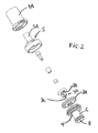
- a system 1 for opening and closing water according to the present invention is schematically represented in exploded form, and in particular a system for opening and closing water in a shower or in a bathroom or kitchen sink.
- the system may be mounted on a shower panel or worktop of the kitchen or bathroom sink and has the function of opening and closing the water and adjusting the flowrate.
- the water is supplied via a diffuser in fluid communication with the system 1, for example a spray head mounted in a fixed or removable manner on the shower panel or a diffuser nozzle mounted on the sink.
- Figure 1 represents a pushbutton 7, a body 5, a shutter 2, a disk 3 and a second body 6 of the system 1 according to the invention.
- the pushbutton 7 comprises a cap 7D on which manual pressure may be applied by the operator; the cap 7D may be covered by a cover 7K so as to provide an aesthetic finish.
- the cap 7D, and its cover if present, has for example a surface area equivalent to that of a finger or slightly greater.
- the system 1 is preferably able to be mounted, in a concealed manner, with only the cap 7D (or its cover) visible and facing the user, preferably flush with the worktop or the shower panel.
- the pushbutton also comprises a pair of toothed wheels 7B, 7C and a spring 7E suitable for positioning a magnet 4 in two different stable positions associated with successive operating actions of the pushbutton 7D.
- the body 5 comprises a cylindrical chamber 5a around which the magnet 4, the toothed wheel 7C, and along a predetermined section, the toothed wheel 7B are slidable.
- the spring 7E is arranged between the body 5 and the toothed wheel 7C containing the magnet 4.
- a threaded hollow body 7A forms a seat for a portion of the body 5, allowing another portion of said body 5 projecting from the cylinder 7A to be coupled with the body 6.
- the body 6 and the body 5 form a bayonet closure or a snap-engaging closure.
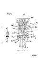
- Figure 2 represents the hollow cylinder 7a and the bodies 5 and 6 in exploded form.
- the magnet 4 is inserted inside the toothed wheel 7C and together with it onto the cylinder chamber 5a, inside the hollow cylinder 7A.
- the teeth of the wheel 7B and the teeth of the wheel 7C cooperate so that successive pressures on the cap 7D (or its cover 7K) displace the magnet 4 into a distal or proximal position of the cylindrical chamber 5a.
- the magnet has two stable (bistable) positions.
- a shutter 2, having at least one metal part 2a, associated with the magnet 4, is situated inside the cylindrical chamber 5a (as visible also Figures 1 and 2 ).
- the shutter 2 engages with the bottom part of the cylindrical chamber 5a, inside it, and has at least a distal part 2c projecting from the cylindrical chamber 5a.
- the shutter 2 engages with the top part of the cylindrical chamber 5a, still inside it, and is completely retracted inside the cylindrical chamber 5a.
- the shutter comprises a seal 2c, which is mounted on the distal part 2c and designed to close a hole 3c in the disk 3, and a plastic spacer 2b.
- the shutter 2 has a metal core 2A, on which the seal 2c is mounted in a distal position and the plastic spacer 2b, along a central section, leaving only the metal part 2a at the end of the shutter exposed to the force of attraction of the magnet 4.
- the spacer allow the dimensions of the magnet, and therefore of the system 1, to be reduced; in fact, the magnet 4 may have a length substantially equal to the length of only a head 2aa ( Fig. 6 ) of the metal part 2a, to guide precisely the shutter 2 inside the cylindrical chamber 5a.
- the pushbutton 7 may be operated with a light pressure, for example with the pressure of a finger, to displace the magnet 4 and the associated shutter 2 and open the water flow from the diffuser or close the flow.
- the pushbutton 7 is configured to return into the same position, before and after closing or opening of the water flow.
- the displacement of the shutter is of few millimetres and merely has the function of triggering a displacement of the fluid shut-off disk 3, which is intended to actually close and open the water flow through the diffuser.
- Full opening of flow corresponds to a maximum distance of the shutter of the disk 3 and full closure of the flow is obtained by bringing the shutter into contact with the disk 3.
- the disk 3 comprises an elastically deformable membrane 3a and a rigid washer 3B on which the membrane is mounted.
- the disk is mounted between the body 5 and a second body 6 and acts as a seal between them.
- the bodies 5 and 6 are fixed together.
- the body 6 has an inlet 9 and an outlet 8 for the water.
- the inlet 9 is designed to receive pressurised water, for example water at a pressure of between 0.1 and 10 bar from the supply network.
- the disk 3 is provided with a hole 3d ( Fig. 2 ) at the inlet 9 and the hole 3c at the outlet 8.
- the disk 3 is subject to the pressure of the incoming water 9 (from the bottom upwards in Figure 1 ) which has the effect of displacing the disk downwards ( Figure 6 ).
- the water Via the hole 3d of the rigid washer 3b, the water may pass through the disk 3, filling the space between the disk and the body and compressing the disk 3 on the outlet 8, with partial deformation of the membrane 3a, in order to close the flow.
- the seal 2c of the shutter closes off the central hole 3c of the rigid washer, thus allowing the pressure of the water (from the top downwards in Figure 6 ) which pushes the membrane and the rigid washer against the outlet 8 to be greater than the pressure of the incoming water 9.
- the shutter projects from the cylindrical chamber and makes contact with the disk 3.
- a chamber 5b is provided in the body 5, in fluid communication with the inlet 9 and the outlet 8, inside which chamber the disk 3 is movable.
- the disk 3 is configured to move so as to close the outlet 9 as a result of filling of the chamber 5b, when the hole 3c is closed off by the shutter 2, or to open the outlet 9, as a result of emptying of the chamber 5a, when the hole 3c is freed by the shutter 2.
- Figure 4 is a cross-sectional view of the system 1, in which the shutter 2 is retracted inside the cylindrical chamber 5a and spaced from the disk 3, leaving the hole 3c in the disk free.
- the water which enters into the chamber 5b through the hole 3d may pass out from the chamber 5b, through the hole 3c, and at the same time may exert a pressure on the disk 3 (from the bottom upwards, in Figure 2 ) which raises the disk from the outlet 8, therefore allowing water to pass through the outlet 8.
- the shutter 2 When the shutter 2 is displaced against the disk 3, it has the function of closing the hole 3c, preventing the water from flowing out of the hole 3c and filling very rapidly the chamber 5c which exerts a pressure (from the top downwards) on the disk 3, compressing the disk against the outlet 8 and preventing the flow of water.
- the cylindrical chamber 5a has a diameter substantially equal to diameter of the shutter and is in fluid communication with the chamber 5a.
- the cylindrical chamber has a length of between 10 and 16 mm and a diameter of between 5 and 10 mm.
- the chamber 5a has a diameter of between 5 and 8 mm.
- the shutter in the cylindrical chamber is not subject to a high water pressure and, advantageously, may be easily displaced inside the chamber 5a.
- the user exerts on the shutter 2 only a pressure needed to cause projection of the shutter from the cylindrical chamber 5a and contact thereof with the disk 3, in order to close the water, or retraction thereof inside the cylindrical chamber 5b and separation from the disk 3, in order to open the flow.
- the rigid washer 3b comprises preferably a shank in the form of a cross 3E or star 3E which can be inserted into the outlet 8; the width of the cross of the shank or the star is substantially the same as a diameter of the outlet 8.
- the washer also comprises a head 3F with a diameter greater than the outlet 8, acting as a plug; the hole 3D is situated on a peripheral part of the head 3F which does not involve the plug.
- the hole 3C has a diameter smaller than the diameter of the outlet 8; when the hole 3C is freed by the shutter, the water flows out of the outlet 8 without entering into the chamber 5a.
- the pushbutton can be operated by means of a finger so as to displace the magnet 4 and the shutter 2 along an axis X of the cylindrical chamber 5a, into two different positions, corresponding to opening of the flow or closing of the flow of water from the diffuser, and is also rotatable about the axis X, in order to vary the open position of the shutter 2 along the axis X and therefore vary a corresponding flowrate.
- Figure 5 shows the piston in an intermediate position or only partially projecting from the cylindrical chamber 5a. In this position, the piston interferes partially with the fluid flow from the inlet 9 to the outlet 8, allowing therefore a reduction in the flow.
- the pushbutton 7, for example the cap 7D is rotatable as a knob, in order to vary an end-of-travel position of the piston 7 in the cylindrical chamber 5a.
- an externally threaded cylinder 20 ( Fig. 3 ) is engaged in a threaded portion of the hollow cylinder 7A and is rotatable by means of the pushbutton 7 (7D), so as to engage with a larger or smaller portion of the hollow cylinder 7A.
- the pushbutton 7 (7D) is provided with tongues 77 which engage inside respective recesses 21 formed in the thickness of the ring 20, on the inner surface 22 of the ring 20. Engagement of the tongues 77 inside the recesses 21 rotationally locks together the ring 20 and the pushbutton 7 (7D).
- a cylinder 79 of the pushbutton 7, passing through the threaded ring 20, is configured to exert a pressure on the toothed wheel 7C which regulates the position of the magnet.
- the pushbutton 7 is fixed, preferably by means of snap-engagement, on the toothed wheel 7B.
- Screwing of the knob 7 or unscrewing thereof from the hollow cylinder 7a may be performed during delivery of the flow, and therefore adjusting in real time the flowrate of the water, or when the water is closed, and therefore adjusting or resetting the flowrate prior to opening.
- Means are envisaged for limiting rotation of the pushbutton 7 about the axis X, preferably limiting the rotation to 180°, for example by means of a locating shoulder 78 or a stop element 78 in the pushbutton 7D.
Landscapes
- Engineering & Computer Science (AREA)
- General Engineering & Computer Science (AREA)
- Mechanical Engineering (AREA)
- Nozzles (AREA)
- Domestic Plumbing Installations (AREA)
- Sliding Valves (AREA)
- Bathtubs, Showers, And Their Attachments (AREA)
Priority Applications (3)
| Application Number | Priority Date | Filing Date | Title |
|---|---|---|---|
| EP13191870.8A EP2865928B1 (fr) | 2013-10-25 | 2013-11-07 | Vanne |
| US14/242,668 US9297475B2 (en) | 2013-10-25 | 2014-04-01 | System for adjusting water in a shower, bathroom, or kitchen sink |
| CN201410265111.5A CN104565432B (zh) | 2013-10-25 | 2014-06-13 | 用于调节淋浴器或浴室水槽或厨房水槽中的水的系统 |
Applications Claiming Priority (2)
| Application Number | Priority Date | Filing Date | Title |
|---|---|---|---|
| EP13190336 | 2013-10-25 | ||
| EP13191870.8A EP2865928B1 (fr) | 2013-10-25 | 2013-11-07 | Vanne |
Publications (2)
| Publication Number | Publication Date |
|---|---|
| EP2865928A1 true EP2865928A1 (fr) | 2015-04-29 |
| EP2865928B1 EP2865928B1 (fr) | 2017-08-23 |
Family
ID=49841483
Family Applications (1)
| Application Number | Title | Priority Date | Filing Date |
|---|---|---|---|
| EP13191870.8A Active EP2865928B1 (fr) | 2013-10-25 | 2013-11-07 | Vanne |
Country Status (2)
| Country | Link |
|---|---|
| EP (1) | EP2865928B1 (fr) |
| ES (2) | ES2647273T3 (fr) |
Cited By (7)
| Publication number | Priority date | Publication date | Assignee | Title |
|---|---|---|---|---|
| EP3447346A1 (fr) * | 2017-07-06 | 2019-02-27 | A. u. K. Müller GmbH & Co. KG | Soupape, en particulier servosoupape |
| EP3587880A1 (fr) * | 2018-06-27 | 2020-01-01 | Beijing Kohler Ltd. | Soupape de commutation avec commande d'écoulement |
| EP3420258B1 (fr) | 2016-02-22 | 2020-02-12 | Neoperl GmbH | Dispositif d'actionnement de soupape |
| US11002371B2 (en) | 2018-06-27 | 2021-05-11 | Beijing Kohler Ltd. | Flow control switch valve |
| DE202021104583U1 (de) | 2021-08-26 | 2021-11-03 | Fabrizio Nobili | Einstellvorrichtung für eine Wasserabgabeeinheit |
| US11261992B2 (en) * | 2017-03-10 | 2022-03-01 | Neoperl Gmbh | Plumbing valve and corresponding series |
| EP4141303A1 (fr) | 2021-08-26 | 2023-03-01 | Fabrizio Nobili | Dispositif d'actionnement de soupape |
Citations (4)
| Publication number | Priority date | Publication date | Assignee | Title |
|---|---|---|---|---|
| DE3109943A1 (de) * | 1981-03-14 | 1982-10-07 | Rotter GmbH & Co KG, 1000 Berlin | Permanentmagnetisch gesteuertes selbstschlussventil |
| GB2103391A (en) * | 1981-07-31 | 1983-02-16 | Peglers Ltd | Servo operated fluid flow taps and valves |
| EP0183102A1 (fr) * | 1984-11-15 | 1986-06-04 | FRIEDRICH GROHE ARMATURENFABRIK GmbH & CO | Dispositif pour commander la quantité de remplissage |
| JP2001098596A (ja) * | 1999-09-29 | 2001-04-10 | Inax Corp | 吐水装置 |
Family Cites Families (1)
| Publication number | Priority date | Publication date | Assignee | Title |
|---|---|---|---|---|
| DE102012221043A1 (de) * | 2012-11-19 | 2014-05-22 | Hansgrohe Se | Sanitärventil |
-
2013
- 2013-11-07 EP EP13191870.8A patent/EP2865928B1/fr active Active
- 2013-11-07 ES ES13191870.8T patent/ES2647273T3/es active Active
-
2014
- 2014-02-17 ES ES14155396.6T patent/ES2621953T3/es active Active
Patent Citations (4)
| Publication number | Priority date | Publication date | Assignee | Title |
|---|---|---|---|---|
| DE3109943A1 (de) * | 1981-03-14 | 1982-10-07 | Rotter GmbH & Co KG, 1000 Berlin | Permanentmagnetisch gesteuertes selbstschlussventil |
| GB2103391A (en) * | 1981-07-31 | 1983-02-16 | Peglers Ltd | Servo operated fluid flow taps and valves |
| EP0183102A1 (fr) * | 1984-11-15 | 1986-06-04 | FRIEDRICH GROHE ARMATURENFABRIK GmbH & CO | Dispositif pour commander la quantité de remplissage |
| JP2001098596A (ja) * | 1999-09-29 | 2001-04-10 | Inax Corp | 吐水装置 |
Cited By (9)
| Publication number | Priority date | Publication date | Assignee | Title |
|---|---|---|---|---|
| EP3420258B1 (fr) | 2016-02-22 | 2020-02-12 | Neoperl GmbH | Dispositif d'actionnement de soupape |
| EP3420258B2 (fr) † | 2016-02-22 | 2023-06-28 | Neoperl GmbH | Dispositif d'actionnement de soupape |
| EP4219990A3 (fr) * | 2016-02-22 | 2023-10-18 | Neoperl GmbH | Dispositif d'actionnement de soupape |
| US11261992B2 (en) * | 2017-03-10 | 2022-03-01 | Neoperl Gmbh | Plumbing valve and corresponding series |
| EP3447346A1 (fr) * | 2017-07-06 | 2019-02-27 | A. u. K. Müller GmbH & Co. KG | Soupape, en particulier servosoupape |
| EP3587880A1 (fr) * | 2018-06-27 | 2020-01-01 | Beijing Kohler Ltd. | Soupape de commutation avec commande d'écoulement |
| US11002371B2 (en) | 2018-06-27 | 2021-05-11 | Beijing Kohler Ltd. | Flow control switch valve |
| DE202021104583U1 (de) | 2021-08-26 | 2021-11-03 | Fabrizio Nobili | Einstellvorrichtung für eine Wasserabgabeeinheit |
| EP4141303A1 (fr) | 2021-08-26 | 2023-03-01 | Fabrizio Nobili | Dispositif d'actionnement de soupape |
Also Published As
| Publication number | Publication date |
|---|---|
| EP2865928B1 (fr) | 2017-08-23 |
| ES2621953T3 (es) | 2017-07-05 |
| ES2647273T3 (es) | 2017-12-20 |
Similar Documents
| Publication | Publication Date | Title |
|---|---|---|
| EP2865929B1 (fr) | Dispositif de réglage de l'eau dans une baignoire ou de douche ou évier de cuisine | |
| EP2865928B1 (fr) | Vanne | |
| US9927042B2 (en) | Multifunctional restrictive valve | |
| EP3147546B1 (fr) | Dispositif pour ouvrir, fermer et réguler un débit pour un corps de robinet d'une salle de bain ou de cuisine | |
| US20110180741A1 (en) | 3-stage temperature control valve | |
| JP2018505979A (ja) | センサ作動式プルアウト水栓 | |
| US10232386B1 (en) | User-friendly water discharge device with pause structure | |
| CN109899588B (zh) | 阀致动装置和卫生阀 | |
| US10634264B2 (en) | Indicator of the opening and/or closing status of a tap or a pressure reducer | |
| EP2054653B1 (fr) | Améliorations pour adaptateurs de robinets | |
| CA2751728C (fr) | Soupape d'arret | |
| EP0424101A1 (fr) | Appareil de commande de robinet d'eau | |
| EP3587880B1 (fr) | Soupape de commutation avec commande d'écoulement | |
| JP2005155797A (ja) | 水栓装置 | |
| EP2156897A1 (fr) | Pomme de douche multifonction | |
| JP2005264979A (ja) | 開閉弁装置及びそれを備えた水栓装置 | |
| US1775499A (en) | Cam faucet | |
| CA2797522A1 (fr) | Module de telecommande servant a controler une vanne d'un raccord de drain | |
| US11867313B2 (en) | Adjustment device for a water delivery unit | |
| KR102016508B1 (ko) | 출수 시간 조절이 가능한 절수형 자폐 밸브 장치 | |
| IT202100004253U1 (it) | Dispositivo di regolazione per unita’ di erogazione-acqua | |
| KR20200000777A (ko) | 수도꼭지 토출구 개폐장치 | |
| BR102015031964A2 (pt) | Automatic closure time regulating device for hydraulic records and hydraulic registry and apparatus | |
| BR102015030323A2 (pt) | válvula hidráulica com controle de tempo de fechamento antivandalismo |
Legal Events
| Date | Code | Title | Description |
|---|---|---|---|
| PUAI | Public reference made under article 153(3) epc to a published international application that has entered the european phase |
Free format text: ORIGINAL CODE: 0009012 |
|
| 17P | Request for examination filed |
Effective date: 20150127 |
|
| AK | Designated contracting states |
Kind code of ref document: A1 Designated state(s): AL AT BE BG CH CY CZ DE DK EE ES FI FR GB GR HR HU IE IS IT LI LT LU LV MC MK MT NL NO PL PT RO RS SE SI SK SM TR |
|
| AX | Request for extension of the european patent |
Extension state: BA ME |
|
| 17Q | First examination report despatched |
Effective date: 20150710 |
|
| GRAP | Despatch of communication of intention to grant a patent |
Free format text: ORIGINAL CODE: EPIDOSNIGR1 |
|
| INTG | Intention to grant announced |
Effective date: 20170322 |
|
| GRAS | Grant fee paid |
Free format text: ORIGINAL CODE: EPIDOSNIGR3 |
|
| GRAA | (expected) grant |
Free format text: ORIGINAL CODE: 0009210 |
|
| AK | Designated contracting states |
Kind code of ref document: B1 Designated state(s): AL AT BE BG CH CY CZ DE DK EE ES FI FR GB GR HR HU IE IS IT LI LT LU LV MC MK MT NL NO PL PT RO RS SE SI SK SM TR |
|
| REG | Reference to a national code |
Ref country code: GB Ref legal event code: FG4D |
|
| REG | Reference to a national code |
Ref country code: CH Ref legal event code: EP |
|
| REG | Reference to a national code |
Ref country code: AT Ref legal event code: REF Ref document number: 921710 Country of ref document: AT Kind code of ref document: T Effective date: 20170915 |
|
| REG | Reference to a national code |
Ref country code: IE Ref legal event code: FG4D |
|
| REG | Reference to a national code |
Ref country code: DE Ref legal event code: R096 Ref document number: 602013025369 Country of ref document: DE |
|
| REG | Reference to a national code |
Ref country code: SE Ref legal event code: TRGR Ref country code: FR Ref legal event code: PLFP Year of fee payment: 5 |
|
| REG | Reference to a national code |
Ref country code: CH Ref legal event code: NV Representative=s name: ING. MARCO ZARDI C/O M. ZARDI AND CO. S.A., CH |
|
| REG | Reference to a national code |
Ref country code: ES Ref legal event code: FG2A Ref document number: 2647273 Country of ref document: ES Kind code of ref document: T3 Effective date: 20171220 |
|
| REG | Reference to a national code |
Ref country code: NL Ref legal event code: MP Effective date: 20170823 |
|
| REG | Reference to a national code |
Ref country code: LT Ref legal event code: MG4D |
|
| PG25 | Lapsed in a contracting state [announced via postgrant information from national office to epo] |
Ref country code: LT Free format text: LAPSE BECAUSE OF FAILURE TO SUBMIT A TRANSLATION OF THE DESCRIPTION OR TO PAY THE FEE WITHIN THE PRESCRIBED TIME-LIMIT Effective date: 20170823 Ref country code: HR Free format text: LAPSE BECAUSE OF FAILURE TO SUBMIT A TRANSLATION OF THE DESCRIPTION OR TO PAY THE FEE WITHIN THE PRESCRIBED TIME-LIMIT Effective date: 20170823 Ref country code: FI Free format text: LAPSE BECAUSE OF FAILURE TO SUBMIT A TRANSLATION OF THE DESCRIPTION OR TO PAY THE FEE WITHIN THE PRESCRIBED TIME-LIMIT Effective date: 20170823 Ref country code: NO Free format text: LAPSE BECAUSE OF FAILURE TO SUBMIT A TRANSLATION OF THE DESCRIPTION OR TO PAY THE FEE WITHIN THE PRESCRIBED TIME-LIMIT Effective date: 20171123 Ref country code: NL Free format text: LAPSE BECAUSE OF FAILURE TO SUBMIT A TRANSLATION OF THE DESCRIPTION OR TO PAY THE FEE WITHIN THE PRESCRIBED TIME-LIMIT Effective date: 20170823 |
|
| PG25 | Lapsed in a contracting state [announced via postgrant information from national office to epo] |
Ref country code: IS Free format text: LAPSE BECAUSE OF FAILURE TO SUBMIT A TRANSLATION OF THE DESCRIPTION OR TO PAY THE FEE WITHIN THE PRESCRIBED TIME-LIMIT Effective date: 20171223 Ref country code: LV Free format text: LAPSE BECAUSE OF FAILURE TO SUBMIT A TRANSLATION OF THE DESCRIPTION OR TO PAY THE FEE WITHIN THE PRESCRIBED TIME-LIMIT Effective date: 20170823 Ref country code: PL Free format text: LAPSE BECAUSE OF FAILURE TO SUBMIT A TRANSLATION OF THE DESCRIPTION OR TO PAY THE FEE WITHIN THE PRESCRIBED TIME-LIMIT Effective date: 20170823 Ref country code: GR Free format text: LAPSE BECAUSE OF FAILURE TO SUBMIT A TRANSLATION OF THE DESCRIPTION OR TO PAY THE FEE WITHIN THE PRESCRIBED TIME-LIMIT Effective date: 20171124 Ref country code: RS Free format text: LAPSE BECAUSE OF FAILURE TO SUBMIT A TRANSLATION OF THE DESCRIPTION OR TO PAY THE FEE WITHIN THE PRESCRIBED TIME-LIMIT Effective date: 20170823 Ref country code: BG Free format text: LAPSE BECAUSE OF FAILURE TO SUBMIT A TRANSLATION OF THE DESCRIPTION OR TO PAY THE FEE WITHIN THE PRESCRIBED TIME-LIMIT Effective date: 20171123 |
|
| PG25 | Lapsed in a contracting state [announced via postgrant information from national office to epo] |
Ref country code: DK Free format text: LAPSE BECAUSE OF FAILURE TO SUBMIT A TRANSLATION OF THE DESCRIPTION OR TO PAY THE FEE WITHIN THE PRESCRIBED TIME-LIMIT Effective date: 20170823 Ref country code: CZ Free format text: LAPSE BECAUSE OF FAILURE TO SUBMIT A TRANSLATION OF THE DESCRIPTION OR TO PAY THE FEE WITHIN THE PRESCRIBED TIME-LIMIT Effective date: 20170823 Ref country code: RO Free format text: LAPSE BECAUSE OF FAILURE TO SUBMIT A TRANSLATION OF THE DESCRIPTION OR TO PAY THE FEE WITHIN THE PRESCRIBED TIME-LIMIT Effective date: 20170823 |
|
| REG | Reference to a national code |
Ref country code: DE Ref legal event code: R097 Ref document number: 602013025369 Country of ref document: DE |
|
| PG25 | Lapsed in a contracting state [announced via postgrant information from national office to epo] |
Ref country code: SM Free format text: LAPSE BECAUSE OF FAILURE TO SUBMIT A TRANSLATION OF THE DESCRIPTION OR TO PAY THE FEE WITHIN THE PRESCRIBED TIME-LIMIT Effective date: 20170823 Ref country code: EE Free format text: LAPSE BECAUSE OF FAILURE TO SUBMIT A TRANSLATION OF THE DESCRIPTION OR TO PAY THE FEE WITHIN THE PRESCRIBED TIME-LIMIT Effective date: 20170823 Ref country code: SK Free format text: LAPSE BECAUSE OF FAILURE TO SUBMIT A TRANSLATION OF THE DESCRIPTION OR TO PAY THE FEE WITHIN THE PRESCRIBED TIME-LIMIT Effective date: 20170823 |
|
| PG25 | Lapsed in a contracting state [announced via postgrant information from national office to epo] |
Ref country code: MC Free format text: LAPSE BECAUSE OF FAILURE TO SUBMIT A TRANSLATION OF THE DESCRIPTION OR TO PAY THE FEE WITHIN THE PRESCRIBED TIME-LIMIT Effective date: 20170823 |
|
| PLBE | No opposition filed within time limit |
Free format text: ORIGINAL CODE: 0009261 |
|
| STAA | Information on the status of an ep patent application or granted ep patent |
Free format text: STATUS: NO OPPOSITION FILED WITHIN TIME LIMIT |
|
| 26N | No opposition filed |
Effective date: 20180524 |
|
| PG25 | Lapsed in a contracting state [announced via postgrant information from national office to epo] |
Ref country code: SI Free format text: LAPSE BECAUSE OF FAILURE TO SUBMIT A TRANSLATION OF THE DESCRIPTION OR TO PAY THE FEE WITHIN THE PRESCRIBED TIME-LIMIT Effective date: 20170823 Ref country code: LU Free format text: LAPSE BECAUSE OF NON-PAYMENT OF DUE FEES Effective date: 20171107 |
|
| REG | Reference to a national code |
Ref country code: BE Ref legal event code: MM Effective date: 20171130 |
|
| REG | Reference to a national code |
Ref country code: IE Ref legal event code: MM4A |
|
| PG25 | Lapsed in a contracting state [announced via postgrant information from national office to epo] |
Ref country code: MT Free format text: LAPSE BECAUSE OF NON-PAYMENT OF DUE FEES Effective date: 20171107 |
|
| PG25 | Lapsed in a contracting state [announced via postgrant information from national office to epo] |
Ref country code: IE Free format text: LAPSE BECAUSE OF NON-PAYMENT OF DUE FEES Effective date: 20171107 |
|
| PG25 | Lapsed in a contracting state [announced via postgrant information from national office to epo] |
Ref country code: BE Free format text: LAPSE BECAUSE OF NON-PAYMENT OF DUE FEES Effective date: 20171130 |
|
| PGFP | Annual fee paid to national office [announced via postgrant information from national office to epo] |
Ref country code: CZ Payment date: 20181108 Year of fee payment: 6 |
|
| REG | Reference to a national code |
Ref country code: DE Ref legal event code: R082 Ref document number: 602013025369 Country of ref document: DE Representative=s name: HGF EUROPE LLP, DE Ref country code: DE Ref legal event code: R082 Ref document number: 602013025369 Country of ref document: DE Representative=s name: HGF EUROPE LP, DE |
|
| PG25 | Lapsed in a contracting state [announced via postgrant information from national office to epo] |
Ref country code: HU Free format text: LAPSE BECAUSE OF FAILURE TO SUBMIT A TRANSLATION OF THE DESCRIPTION OR TO PAY THE FEE WITHIN THE PRESCRIBED TIME-LIMIT; INVALID AB INITIO Effective date: 20131107 |
|
| PG25 | Lapsed in a contracting state [announced via postgrant information from national office to epo] |
Ref country code: CY Free format text: LAPSE BECAUSE OF FAILURE TO SUBMIT A TRANSLATION OF THE DESCRIPTION OR TO PAY THE FEE WITHIN THE PRESCRIBED TIME-LIMIT Effective date: 20170823 |
|
| PG25 | Lapsed in a contracting state [announced via postgrant information from national office to epo] |
Ref country code: MK Free format text: LAPSE BECAUSE OF FAILURE TO SUBMIT A TRANSLATION OF THE DESCRIPTION OR TO PAY THE FEE WITHIN THE PRESCRIBED TIME-LIMIT Effective date: 20170823 |
|
| PG25 | Lapsed in a contracting state [announced via postgrant information from national office to epo] |
Ref country code: PT Free format text: LAPSE BECAUSE OF FAILURE TO SUBMIT A TRANSLATION OF THE DESCRIPTION OR TO PAY THE FEE WITHIN THE PRESCRIBED TIME-LIMIT Effective date: 20170823 |
|
| REG | Reference to a national code |
Ref country code: SE Ref legal event code: EUG |
|
| PG25 | Lapsed in a contracting state [announced via postgrant information from national office to epo] |
Ref country code: AL Free format text: LAPSE BECAUSE OF FAILURE TO SUBMIT A TRANSLATION OF THE DESCRIPTION OR TO PAY THE FEE WITHIN THE PRESCRIBED TIME-LIMIT Effective date: 20170823 |
|
| PG25 | Lapsed in a contracting state [announced via postgrant information from national office to epo] |
Ref country code: SE Free format text: LAPSE BECAUSE OF NON-PAYMENT OF DUE FEES Effective date: 20191108 |
|
| REG | Reference to a national code |
Ref country code: AT Ref legal event code: UEP Ref document number: 921710 Country of ref document: AT Kind code of ref document: T Effective date: 20170823 |
|
| PGFP | Annual fee paid to national office [announced via postgrant information from national office to epo] |
Ref country code: GB Payment date: 20231127 Year of fee payment: 11 |
|
| PGFP | Annual fee paid to national office [announced via postgrant information from national office to epo] |
Ref country code: ES Payment date: 20231201 Year of fee payment: 11 |
|
| PGFP | Annual fee paid to national office [announced via postgrant information from national office to epo] |
Ref country code: TR Payment date: 20231031 Year of fee payment: 11 Ref country code: IT Payment date: 20231123 Year of fee payment: 11 Ref country code: FR Payment date: 20231127 Year of fee payment: 11 Ref country code: DE Payment date: 20231129 Year of fee payment: 11 Ref country code: CH Payment date: 20231201 Year of fee payment: 11 Ref country code: AT Payment date: 20231102 Year of fee payment: 11 |