EP3405062B1 - Dispositif de fermeture permettant de relier deux pièces de manière détachable - Google Patents
Dispositif de fermeture permettant de relier deux pièces de manière détachable Download PDFInfo
- Publication number
- EP3405062B1 EP3405062B1 EP16828718.3A EP16828718A EP3405062B1 EP 3405062 B1 EP3405062 B1 EP 3405062B1 EP 16828718 A EP16828718 A EP 16828718A EP 3405062 B1 EP3405062 B1 EP 3405062B1
- Authority
- EP
- European Patent Office
- Prior art keywords
- closure
- closure device
- magnetic
- closed position
- fit
- Prior art date
- Legal status (The legal status is an assumption and is not a legal conclusion. Google has not performed a legal analysis and makes no representation as to the accuracy of the status listed.)
- Active
Links
- 230000005291 magnetic effect Effects 0.000 claims description 31
- 230000005415 magnetization Effects 0.000 claims description 19
- 238000010008 shearing Methods 0.000 description 8
- 238000000034 method Methods 0.000 description 6
- 230000000295 complement effect Effects 0.000 description 2
- 239000004677 Nylon Substances 0.000 description 1
- 230000003993 interaction Effects 0.000 description 1
- 239000000463 material Substances 0.000 description 1
- 229920001778 nylon Polymers 0.000 description 1
- 230000008093 supporting effect Effects 0.000 description 1
Images


Classifications
-
- A—HUMAN NECESSITIES
- A44—HABERDASHERY; JEWELLERY
- A44B—BUTTONS, PINS, BUCKLES, SLIDE FASTENERS, OR THE LIKE
- A44B11/00—Buckles; Similar fasteners for interconnecting straps or the like, e.g. for safety belts
- A44B11/25—Buckles; Similar fasteners for interconnecting straps or the like, e.g. for safety belts with two or more separable parts
- A44B11/258—Buckles; Similar fasteners for interconnecting straps or the like, e.g. for safety belts with two or more separable parts fastening by superposing one part on top of the other
-
- A—HUMAN NECESSITIES
- A41—WEARING APPAREL
- A41F—GARMENT FASTENINGS; SUSPENDERS
- A41F1/00—Fastening devices specially adapted for garments
- A41F1/002—Magnetic fastening devices
-
- A—HUMAN NECESSITIES
- A44—HABERDASHERY; JEWELLERY
- A44C—PERSONAL ADORNMENTS, e.g. JEWELLERY; COINS
- A44C5/00—Bracelets; Wrist-watch straps; Fastenings for bracelets or wrist-watch straps
- A44C5/18—Fasteners for straps, chains or the like
- A44C5/20—Fasteners for straps, chains or the like for open straps, chains or the like
- A44C5/2071—Fasteners for straps, chains or the like for open straps, chains or the like with the two ends of the strap or chain overlapping each other and fastened by an action perpendicularly to the main plane of these two ends
-
- A—HUMAN NECESSITIES
- A44—HABERDASHERY; JEWELLERY
- A44D—INDEXING SCHEME RELATING TO BUTTONS, PINS, BUCKLES OR SLIDE FASTENERS, AND TO JEWELLERY, BRACELETS OR OTHER PERSONAL ADORNMENTS
- A44D2203/00—Fastening by use of magnets
-
- A—HUMAN NECESSITIES
- A45—HAND OR TRAVELLING ARTICLES
- A45C—PURSES; LUGGAGE; HAND CARRIED BAGS
- A45C13/00—Details; Accessories
- A45C13/10—Arrangement of fasteners
- A45C13/1069—Arrangement of fasteners magnetic
Definitions
- the invention relates in particular to a locking device for detachably connecting two parts to one another according to the preamble of claim 1.
- Such a closure device comprises the features of claim 1.
- closure devices there is often the task, on the one hand, of allowing simple operation when closing and opening and, on the other hand, of ensuring a secure closed position from which no unintentional opening of the closure device is possible.
- the DE 10 2007 024 118 A1 which discloses the preamble of claim 1, describes a closure of the type of a zipper, in which magnetic elements are coupled and lined up with one another in a closed position.
- a mechanical hold is provided here by engagement of an element in an associated recess on an adjacent closure element.
- U.S. 2004/0107547 A1 describes a closure device in which a closure element with a hook in a closed position is positively engaged with a closure element with a counter-hook.
- U.S. 4,941,236 describes a clasp for a wristwatch which, for example, can have sawtooth-shaped, magnetized sections in cross section.
- the EP 0 923 887 A2 describes a magnetic closure device in which two closure parts can be attached to one another and are held together magnetically in a closed position.
- this object is achieved by a closure device of the type mentioned at the beginning with the characterizing feature of claim 1 .
- the first closure part has at least one first form-fitting section and that the second closure part has at least one second form-fitting section, wherein in the closed position the at least one first form-fitting section and the at least one second form-fitting section engage with one another in a form-fitting manner in order to form a line parallel to the Closing direction directed relative movement of the closure parts relative to each other, through which the closure parts would be removed from each other to prevent.
- the form-fitting sections of the first closure part on the one hand and of the second closure part on the other hand engage behind each other in the closed position in a form-fit manner with respect to the closing direction.
- the form-fitting engagement of the two closure parts with one another enables a secure connection in the closed position of the closure device.
- shearing forces acting on the closure parts can be absorbed as a result.
- the closure parts can preferably be designed to be essentially rigid.
- the closure parts can consist at least partially of a nylon material.
- the at least one first form-fitting section and the at least one second form-fitting section have a form-fitting surface running obliquely to the closing direction. In the closed position, the oblique form-fitting surface is engaged behind by a complementary form-fitting surface on the respective other form-fitting section.
- At least one of the closure parts is provided with at least one first guide section, which is designed to specify a relative movement of the closure parts against one another, when the closure parts are placed on one another, perpendicular to the closing direction, in order to move the at least one first form-fitting section and the at least one second form-fitting section together to bring the positive engagement.
- a multiplicity of first and second magnet sections are provided.
- the second magnet sections can be at least partially accommodated by a multiplicity of intermediate spaces which are each formed between two first magnet sections.
- At least one of the magnet sections comprises a permanent magnet having a cross-section in the shape of a non-rectangular parallelogram.
- the first closure part and/or the second closure part comprises a base body which extends essentially parallel to a respective extension plane. In the closed position of the closure device, the closing direction is perpendicular to the plane of extension of the first closure part and/or to the plane of extension of the second closure part.
- At least one magnet section provided on a closure part and/or at least one permanent magnet provided on a closure part can have at least one surface aligned obliquely to the plane of extension of the base body, which forms a form-fitting surface, a guide surface and/or a contact section.
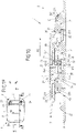
- FIGS. 1A to 1I show different views of a first exemplary embodiment of a closure device 1 with magnet sections 21, 31 and positive-locking sections 23, 33.
- a closure device 1 can generally be provided for the detachable connection of two parts to one another.
- a closure device 1 can be arranged on a piece of clothing or on a bag.
- the closure device 1 comprises a first closure part 2 and a second closure part 3, the two closure parts 2, 3 for closing the closure device 1 along a closing direction Z being attachable to one another.
- Each closure part 2, 3 has a base body 20, 30, which essentially extends in a respective extension plane XY, X'Y'.
- first magnet sections 21 are arranged on the base body 20 of the first closure part 2, with two adjacent magnet sections 21 being spaced apart from one another and forming an intermediate space 22 between one another.
- a second magnet section 31 is arranged on a side of the base body 30 of the second closure part 3 that faces the first magnet sections 21 .
- each first magnet section 21 comprises a first permanent magnet 211 with a first magnetization direction M1, the first magnetization direction M1 pointing from a north pole N to a south pole S of the respective first permanent magnet 211.
- the second magnet section 31 also includes a second permanent magnet 311 with a second magnetization direction M2, which points from a north pole N to a south pole S of the second permanent magnet 311.
- the permanent magnets 211, 311 are arranged in recesses provided for this purpose in the first magnet sections 21 and the second magnet section 31, respectively.
- the first closure part 2 and the second closure part 3 can be attached to one another along the closing direction Z in such a way that the closure device 1 has a Figure 1I shown closed position occupies.
- the respective extension planes XY, X'Y' of the base body 20, 30 of the first closure part 2 and the second closure part 3 in the closed position run essentially parallel to one another and perpendicular to the closing direction Z.
- the permanent magnets 211, 311 are arranged in the respective magnet sections 21, 31 in such a way that the first direction of magnetization M1 and the second direction of magnetization M2 run parallel to one another and are essentially perpendicular to the closed position Z are.
- the magnetization directions M1, M2 and the attractive magnetic forces K1, K2 run essentially parallel to the extension planes XY, X'Y' of the base bodies 20, 30.
- FIGS. 1B to 1I illustrate an example of a possible closing process of the closure device 1 Figures 1B , 1D , 1F and 1H each provide a top view of the closure device 1 according to FIG Figure 1A in dar, and each subsequent Figures 1C , 1E , 1G and 1I show associated sectional views along the respective section line AA.
- FIGS Figures 1B and 1C an open state of the closure device 1 is shown.
- Figures 1H and 1I a closed position of the closure device 1.
- Possible intermediate positions which the closure device 1 can assume during a closing process are shown in FIGS Figures 1D to 1G shown.
- the first closure part 2 includes six positive-locking sections 23, two of which laterally frame a magnet section 21 and each have a positive-locking surface 231 running obliquely to the closing direction.
- the three form-fitting sections 23 are arranged at regular intervals from one another on the base body 20 of the first closure part 2 .
- the second closure part 3 comprises two complementary to the first form-fitting sections 23 second form-fitting sections 33, the frame the second magnet section 31 laterally and each have a form-fitting surface 331 running obliquely to the closing direction Z.
- the first form-fitting sections 23, on the one hand, and the second form-fitting sections 33, on the other hand, are provided and arranged so that they engage with one another in a form-fitting manner when the closure device 1 is in the closed position such that a relative movement of the closure parts 2, 3 relative to one another, directed counter to the closing direction Z, by which the Closure parts 2, 3 would be removed from each other is prevented.
- the form-fitting sections 23, 33 of the first closure part 2 on the one hand and of the second closure part 3 on the other hand engage behind each other in the closed position in a form-fit manner with respect to the closing direction Z, see FIG Figure 1I .
- the inclined form-fitting surfaces 231 of the first form-fitting sections 23 face the base body 20 of the first closure part 2 .
- the form-fitting surfaces 331 of the second form-fitting sections 33 face the base body 30 of the second closure part 3 accordingly.
- the form-fitting engagement of the two closure parts 2, 3 by means of the form-fitting sections 23, 33 enables a secure connection in the closed position of the closure device 1. Unintentional opening of the closure device 1 due to a relative movement of the closure parts 2, 3 counter to the closing direction Z, through which the two closure parts 2, 3 would be separated from each other can thus be prevented. In addition, external shearing forces, which can act perpendicularly to the closing direction Z on the closure parts 2, 3, can be absorbed by the form closure of the form closure sections 23, 33 with one another.
- first form-fitting sections 23 and/or the second form-fitting sections 33 can be formed by a "real" mechanical undercut on the respective closure part 2, 3, with the first form-fitting sections 23 and/or the second form-fitting sections 33 each have at least one form-fitting surface running essentially perpendicularly to the closing direction Z.
- first guide sections 24, 34 are provided on the two closure parts 2, 3 in each case.
- the first guide sections 24, 34 in the exemplary embodiment shown are designed as first guide surfaces 241, 341 running obliquely to the closing direction Z on the positive-locking sections 23, 33, which laterally frame the magnet sections 21, 31.
- the first guide sections 24, 34 are designed so that, when the closure parts 2, 3 are placed on one another, a relative movement R2 of the closure parts 2, 3 directed perpendicularly to the closing direction Z against one another is specified in order to move the at least one first form-fitting section 23 and the at least one second form-fitting section 33 to bring each other into the form-fitting engagement that the in Figure 1I shown closed position corresponds.
- first guide surfaces 241 of the first closure part 2 each form a first contact section 25 for sliding on the first guide surfaces 341 of the second closure part 3.
- first guide surfaces 341 of the second closure part 3 each form a first contact section 35 for sliding on the first guide surfaces 241 of the first closure part 2.
- the second closure part 3 when the second closure part 3 is attached to the first closure part 2 in the closing direction Z, the second closure part 3 can slide with its first contact sections 35 on the first guide surfaces 241 of the first closure part 2 and thereby be deflected perpendicularly to the closing direction Z (according to the Figure 1G relative movement R2 drawn in) that the form-fitting surfaces 231, 331 of the first closure part 2 and of the second closure part 3 come into positive engagement with one another in order to prevent a relative movement directed parallel to the closing direction Z, through which the closure parts 2, 3 would be moved apart.
- the second closure part 3 When sliding on the first guide surfaces 241 of the first closure part 2, the second closure part 3 is loaded with a shearing force perpendicular to the closing direction Z, which causes the movement to be deflected and the relative movement R2 resulting therefrom into the closed position.
- This process corresponds to the step of in the Figure 1G shown intermediate position of the closure device 1 to the in Figure 1I shown closed position.
- the first magnet sections 21 and the magnet section 31 are arranged one behind the other collinear with the effective direction of the shearing force occurring for assuming the closed position, ie with the direction of the relative movement R2.
- the first direction of magnetization M1 of the first permanent magnets 211 arranged in the first magnet sections 21 and the second direction of magnetization M2 of the second permanent magnet 311 arranged in the second magnet section 31 run parallel to one another and are essentially perpendicular to the closing direction Z.
- the first magnet sections 21 and the second magnet section 31 are arranged one behind the other.
- external shearing forces acting on the closure parts 2, 3 in the direction of the relative movement R2 can be absorbed by the form-fitting engagement of the form-fitting sections 23, 33 in the closed position.
- second guide sections 27, 37 are provided on the two closure parts 2, 3 in each case.
- the second guide sections 27, 37 are also designed as second guide surfaces 271, 371 running obliquely to the closing direction Z on the positive-locking sections 23, 33, which laterally frame the magnet sections 21, 31.
- the function of the second guide sections 27, 37 is derived from the step in Figure 1E shown intermediate position to the in Figure 1G shown intermediate position visible. Accordingly, the second guide sections 27, 37 are designed so that when the closure parts 2, 3 are placed on one another, a first relative movement R1 of the closure parts 2, 3 directed perpendicularly to the closing direction Z against one another is initially specified in order to guide the first guide sections 24 of the first closure part 2 on the one hand and the first On the other hand, to bring guide sections 34 of the second closure part 3 into contact with one another (cf. Figure 1G ).
- the second guide surfaces 271 of the first closure part 2 each form a second contact section 26 for sliding on the second guide surfaces 371 of the second closure part 3.
- the second guide surfaces 371 of the second closure part 3 each form a second contact section 36 for sliding on the second guide surfaces 271 of the first closure part 2.
- the second closure part 3 can slide with its second contact sections 36 on the second guide surfaces 271 of the first closure part 2 and thereby be deflected perpendicularly to the closing direction Z (according to the Figure 1E drawn-in first relative movement R1) that the first guide surfaces 241, 341 of the first closure part 2 and of the second closure part 3 come into contact with one another (see Figure 1G ).
- the described interaction of the second guide sections 27, 37 and the first guide sections 24, 34 ensures a certain tolerance when attaching the closure parts 2, 3 to one another, which simplifies the closing of the closure device 1 for a user. In this way, the user does not have to make an effort to attach the two closure parts 2, 3 to one another in a targeted manner in the region of their first guide sections 27, 37.
- the first closure part 2 comes into direct contact with the first guide section 34 of the other closure part 3 without being deflected beforehand on the second guide section 37 .
- the attachment can take place in the area of the entire width of the first guide sections 24, 34, so that a particularly targeted attachment is not necessary.
- the first guide sections 24 , 34 taken by themselves thus also contribute to a tolerance in the attachment movement and thus to a particularly simple closing process of the closure device 1 .
- Figure 2A shows a second exemplary embodiment of a closure device 1 according to the invention in a perspective exploded view
- Figure 2B provides the closure device 1 according to FIG Figure 2A in a plan.
- Figure 2C is an associated sectional view along the in Figure 2B drawn section line AA shown.
- the Figure 2D shows a sectional view of the closure device 1 according to the second embodiment in its closed position.
- the closure device 1 shown has a similar basic structure and function as that referred to in FIG Figures 1A to 1I described closure device 1.
- the above description of the first embodiment thus applies in principle to the second embodiment according to Figures 2A to 2D .
- Both the magnet sections 21, 31 and the permanent magnets 211, 311 arranged therein each have a cross-section in the form of a non-rectangular parallelogram (see in particular Figures 2C and 2D ).
- the first form-fitting sections 23 and the second form-fitting sections 33 are each formed by a surface of a magnet section 21, 31 that runs obliquely to the closing direction Z.
- the following advantage if the second closure part 3 is to be moved from a first closed position, in which it is accommodated by a first intermediate space 22-1, into a second closed position, in which it is accommodated by a second intermediate space 22-2 This is done by a force F applied perpendicularly to the closing direction Z, without the closure device 1 first having to be opened with a force acting counter to the closing direction Z, since the side surfaces of the magnet sections with a parallelogram cross-section redirect the force F accordingly.
- the locking device 1 thus acts in a similar way to a freewheel, which locks in one direction and can be easily adjusted in the other direction.
- the closure device 1 can also be opened in a particularly simple manner as a result.
Claims (13)
- Dispositif de fermeture (1) pour la liaison détachable de deux parties l'une avec l'autre, avec- une première partie de fermeture (2) qui comporte au moins deux premières sections magnétiques (21) qui sont espacées l'une de l'autre et réalisent entre elles un espace intermédiaire (22) et- une seconde partie de fermeture (3) qui comporte au moins une seconde section magnétique (31), dans lequel la première partie de fermeture (2) et la seconde partie de fermeture (3) peuvent être placées l'une contre l'autre le long d'un sens de fermeture (Z) de telle manière que le dispositif de fermeture (1) occupe une position de fermeture, dans laquelle l'au moins une seconde section magnétique (31) est reçue au moins partiellement par l'espace intermédiaire (22), dans lequel respectivement une force magnétique attractive (K1, K2) agit dans la position de fermeture entre l'au moins une seconde section magnétique (31) d'une part et chacune des au moins deux premières sections magnétiques (21) réalisant l'espace intermédiaire (22) d'autre part, laquelle est dirigée sensiblement perpendiculairement au sens de fermeture (Z),dans lequel la première partie de fermeture (2) présente au moins une première section de complémentarité de formes (23) et que la seconde partie de fermeture (3) présente au moins une seconde section de complémentarité de formes (33), dans lequel dans la position de fermeture, l'au moins une première section de complémentarité de formes (23) et l'au moins une seconde section de complémentarité de formes (33) sont en prise par complémentarité de formes l'une avec l'autre afin d'empêcher un mouvement relatif dirigé parallèlement au sens de fermeture (Z) des parties de fermeture (2, 3) l'une contre l'autre, le dispositif de fermeture est caractérisé en ce quel'au moins une première section de complémentarité de formes (23) et l'au moins une seconde section de complémentarité de formes (33) présentent une surface de complémentarité de formes (231, 331) s'étendant en oblique par rapport au sens de fermeture (Z), dans lequel la première surface de complémentarité de formes (231) et la seconde surface de complémentarité de formes (331) viennent en prise dans la position de fermeture l'une derrière l'autre.
- Dispositif de fermeture (1) selon la revendication 1, caractérisé en ce que la première partie de fermeture (2) comporte une pluralité de premières sections magnétiques (21) qui sont espacées uniformément les unes des autres, dans lequel respectivement deux des premières sections magnétiques (21) réalisent entre elles un espace intermédiaire (22) qui est réalisé afin de recevoir au moins partiellement l'au moins une seconde section magnétique (31) dans la position de fermeture.
- Dispositif de fermeture (1) selon l'une quelconque des revendications précédentes, caractérisé en ce qu'au niveau d'au moins une des parties de fermeture (2, 3), au moins une première section de guidage (24, 34) est prévue, laquelle est réalisée afin de prédéfinir lors du placement des parties de fermeture (2, 3) l'une contre l'autre un mouvement relatif (R2) dirigé perpendiculairement au sens de fermeture (Z) des parties de fermeture (2, 3) afin de mettre dans la prise de complémentarité de formes entre elles l'au moins une première section de complémentarité de formes (23) et l'au moins une seconde section de complémentaire de formes (33).
- Dispositif de fermeture selon la revendication 3, caractérisé en ce que l'au moins une première section de guidage (24, 34) est formée par une surface s'étendant en oblique par rapport au sens de fermeture (Z) d'au moins une section magnétique (21, 31).
- Dispositif de fermeture (1) selon la revendication 3 ou 4, caractérisé en ce que l'au moins une première section de guidage (24, 34) comporte au moins une première surface de guidage (241, 341) s'étendant en oblique par rapport au sens de fermeture (Z).
- Dispositif de fermeture (1) selon l'une quelconque des revendications précédentes, caractérisé en ce que l'au moins une première section de complémentarité de formes (23) et/ou l'au moins une seconde section de complémentarité de formes (33) est réalisée par une contre-dépouille au niveau de la partie de fermeture (2, 3) respective.
- Dispositif de fermeture (1) selon la revendication 6, caractérisé en ce que la première et/ou seconde section de complémentarité de formes (23, 33) réalisée par une contre-dépouille au niveau de la partie de fermeture (2, 3) respective présente au moins une surface de complémentarité de formes s'étendant sensiblement perpendiculairement au sens de fermeture (Z).
- Dispositif de fermeture (1) selon l'une quelconque des revendications précédentes, caractérisé en ce que l'au moins une première section magnétique (21) comporte au moins un premier aimant permanent (211) avec un premier sens de magnétisation (M1) et que l'au moins une seconde section magnétique (31) comporte au moins un second aimant (311) avec un second sens de magnétisation (M2).
- Dispositif de fermeture (1) selon la revendication 8, caractérisé en ce que l'au moins une première section magnétique (21) et l'au moins une seconde section magnétique (31) sont agencées dans la position de fermeture du dispositif de fermeture (1) de telle manière que le premier sens de magnétisation (M1) et le second sens de magnétisation (M2) s'étendent parallèlement l'un à l'autre et soient dirigés sensiblement perpendiculairement au sens de fermeture (Z).
- Dispositif de fermeture (1) selon la revendication 9, caractérisé en ce que dans la position de fermeture du dispositif de fermeture (1), l'au moins une première section magnétique (21) et l'au moins une seconde section magnétique (31) sont agencées l'une derrière l'autre par rapport au premier sens de magnétisation (M1) et au second sens de magnétisation (M2).
- Dispositif de fermeture (1) selon l'une quelconque des revendications précédentes, caractérisé en ce qu'au moins une des sections magnétiques (21, 31) et/ou au moins un des aimants permanents (211, 311) présente une section transversale sous la forme d'un parallélogramme non rectangulaire.
- Dispositif de fermeture (1) selon l'une quelconque des revendications précédentes, caractérisé en ce que la première partie de fermeture (2) et la seconde partie de fermeture (3) sont réalisées avec la même structure à l'exception du sens de magnétisation (M1, M2) respectif des premier et second aimants permanents (211, 311).
- Dispositif de fermeture (1) selon l'une quelconque des revendications précédentes, caractérisé en ce que la seconde partie de fermeture (3) comporte une pluralité de secondes sections magnétiques (31) qui sont espacées uniformément les unes des autres, dans lequel respectivement deux des secondes sections magnétiques (31) réalisent entre elles un espace intermédiaire (32) qui est réalisé afin de recevoir au moins partiellement l'au moins une première section magnétique (21) dans la position de fermeture.
Applications Claiming Priority (2)
| Application Number | Priority Date | Filing Date | Title |
|---|---|---|---|
| DE102016200944 | 2016-01-23 | ||
| PCT/EP2016/081805 WO2017125229A1 (fr) | 2016-01-23 | 2016-12-19 | Dispositif de fermeture permettant de relier deux pièces de manière détachable |
Publications (2)
| Publication Number | Publication Date |
|---|---|
| EP3405062A1 EP3405062A1 (fr) | 2018-11-28 |
| EP3405062B1 true EP3405062B1 (fr) | 2023-01-25 |
Family
ID=57838316
Family Applications (1)
| Application Number | Title | Priority Date | Filing Date |
|---|---|---|---|
| EP16828718.3A Active EP3405062B1 (fr) | 2016-01-23 | 2016-12-19 | Dispositif de fermeture permettant de relier deux pièces de manière détachable |
Country Status (6)
| Country | Link |
|---|---|
| US (1) | US11083251B2 (fr) |
| EP (1) | EP3405062B1 (fr) |
| JP (1) | JP6932134B2 (fr) |
| KR (1) | KR102623232B1 (fr) |
| CN (1) | CN108495569A (fr) |
| WO (1) | WO2017125229A1 (fr) |
Families Citing this family (11)
| Publication number | Priority date | Publication date | Assignee | Title |
|---|---|---|---|---|
| DE102016218267A1 (de) * | 2016-09-22 | 2018-03-22 | Fidlock Gmbh | Verschlussvorrichtung zum Verbinden zweier Teile |
| US10954055B2 (en) | 2017-03-08 | 2021-03-23 | Yeti Coolers, Llc | Container with magnetic closure |
| DE102017210140A1 (de) | 2017-06-16 | 2018-12-20 | Fidlock Gmbh | Verschlussvorrichtung zum lösbaren Verbinden zweier Teile |
| DE102018213836A1 (de) | 2018-08-16 | 2020-02-20 | Fidlock Gmbh | Verschlussvorrichtung zum lösbaren Verbinden zweier Teile |
| WO2020181243A1 (fr) * | 2019-03-07 | 2020-09-10 | Yeti Coolers, Llc | Récipient à fermeture magnétique |
| USD935175S1 (en) | 2019-03-08 | 2021-11-09 | Yeti Coolers, Llc | Bag |
| CN111824234B (zh) * | 2019-04-16 | 2023-09-01 | 纽维尔品牌日本合同会社 | 附有座椅的育儿器具及连结具 |
| USD957200S1 (en) | 2020-06-03 | 2022-07-12 | Yeti Coolers, Llc | Bag |
| US11272764B1 (en) * | 2020-09-02 | 2022-03-15 | Duraflex Hong Kong Limited | Magnetic buckle |
| DE102021200260B3 (de) * | 2021-01-13 | 2022-03-24 | Fidlock Gmbh | Magnet-mechanische Verschlussvorrichtung |
| US11533970B1 (en) | 2021-11-29 | 2022-12-27 | Duraflex Hong Kong Limited | Magnetic buckle |
Citations (1)
| Publication number | Priority date | Publication date | Assignee | Title |
|---|---|---|---|---|
| EP0923887A2 (fr) * | 1997-12-22 | 1999-06-23 | SAMA S.p.A. | Fermeture magnétique à verrouillage mutuel pour sacs, sacs à dos, vêtements et équivalents |
Family Cites Families (20)
| Publication number | Priority date | Publication date | Assignee | Title |
|---|---|---|---|---|
| US3266112A (en) * | 1964-05-14 | 1966-08-16 | Thomas P Heckman | Permanent magnet fastener |
| US3842194A (en) * | 1971-03-22 | 1974-10-15 | Rca Corp | Information records and recording/playback systems therefor |
| US4399595A (en) * | 1981-02-11 | 1983-08-23 | John Yoon | Magnetic closure mechanism |
| JPS58105430U (ja) | 1982-01-05 | 1983-07-18 | 株式会社井上ジャパックス研究所 | 磁石係止手段を有するバンド |
| US4941236A (en) * | 1989-07-06 | 1990-07-17 | Timex Corporation | Magnetic clasp for wristwatch strap |
| US5664298A (en) * | 1996-04-30 | 1997-09-09 | Nessar-Ivanovic; Lori J. | Jewelry clasp |
| ITMI981150A1 (it) * | 1998-05-22 | 1999-11-22 | Sama S P A | Dispositivo di chiusura magnetica per capi di abbigliamento pelletteria e simili |
| US6857169B2 (en) | 2002-12-10 | 2005-02-22 | Taiwan Industrial Fastener Corporation | Structure of magnetic buckle |
| JP4464802B2 (ja) * | 2004-11-30 | 2010-05-19 | Ykk株式会社 | ファスナー |
| JP5087219B2 (ja) * | 2005-11-08 | 2012-12-05 | 出光ユニテック株式会社 | 咬合具、これを用いた袋およびこれらの製造方法 |
| JP4610521B2 (ja) | 2006-05-30 | 2011-01-12 | Ykk株式会社 | ファスナー |
| JP5301650B2 (ja) * | 2009-03-05 | 2013-09-25 | Ykk株式会社 | ファスナーチェーン及びファスナー |
| DE202009006189U1 (de) * | 2009-04-27 | 2010-09-16 | Joensson, Wolfgang | Magnetverschluss |
| US8844100B2 (en) * | 2010-03-19 | 2014-09-30 | John Edward Faget Humphries | Jewelry clasp and methods thereof |
| JP5599944B2 (ja) | 2011-06-17 | 2014-10-01 | Ykk株式会社 | 磁性ファスナー |
| CN202618405U (zh) | 2012-05-16 | 2012-12-26 | 高珊珊 | 一种磁扣皮带 |
| EP2679113B1 (fr) * | 2012-06-27 | 2014-12-17 | The Swatch Group Research and Development Ltd. | Fermoir magnétique |
| EP2833754B1 (fr) * | 2012-12-14 | 2016-04-27 | Fidlock GmbH | Dispositif de fermeture pour relier deux pièces de manière détachable |
| CN105228480B (zh) | 2013-05-08 | 2018-09-25 | 费得洛克有限公司 | 闭合装置 |
| US9721712B2 (en) * | 2015-04-14 | 2017-08-01 | Boston Inventions, LLC | Hybrid mechanical and magnetic fastening system |
-
2016
- 2016-12-19 US US16/071,182 patent/US11083251B2/en active Active
- 2016-12-19 CN CN201680079796.1A patent/CN108495569A/zh active Pending
- 2016-12-19 EP EP16828718.3A patent/EP3405062B1/fr active Active
- 2016-12-19 KR KR1020187023311A patent/KR102623232B1/ko active IP Right Grant
- 2016-12-19 WO PCT/EP2016/081805 patent/WO2017125229A1/fr active Application Filing
- 2016-12-19 JP JP2018538227A patent/JP6932134B2/ja active Active
Patent Citations (1)
| Publication number | Priority date | Publication date | Assignee | Title |
|---|---|---|---|---|
| EP0923887A2 (fr) * | 1997-12-22 | 1999-06-23 | SAMA S.p.A. | Fermeture magnétique à verrouillage mutuel pour sacs, sacs à dos, vêtements et équivalents |
Also Published As
| Publication number | Publication date |
|---|---|
| KR20180105170A (ko) | 2018-09-27 |
| CN108495569A (zh) | 2018-09-04 |
| KR102623232B1 (ko) | 2024-01-09 |
| WO2017125229A1 (fr) | 2017-07-27 |
| US11083251B2 (en) | 2021-08-10 |
| US20190343239A1 (en) | 2019-11-14 |
| JP2019502493A (ja) | 2019-01-31 |
| EP3405062A1 (fr) | 2018-11-28 |
| JP6932134B2 (ja) | 2021-09-08 |
Similar Documents
| Publication | Publication Date | Title |
|---|---|---|
| EP3405062B1 (fr) | Dispositif de fermeture permettant de relier deux pièces de manière détachable | |
| EP3638069B1 (fr) | Dispositif de verrouillage pour relier deux pièces de manière détachable | |
| DE202013101519U1 (de) | Duschtür-Baugruppe | |
| DE2748546A1 (de) | Reissverschluss mit wenigstens einem schieber | |
| DE3736254C2 (fr) | ||
| DE2438237C3 (de) | Schieber für mit kettengewirkten Tragbändern versehene Reißverschlüsse | |
| DE935662C (de) | Reissverschluss und Verfahren zu seiner Herstellung | |
| DE10342223B4 (de) | Verbindungselement | |
| DE3201135C2 (fr) | ||
| DE2644040C2 (de) | Winkelverbindung für Bauteile, insbesondere Profilleisten, Profilträger u.dgl. | |
| DE2327527A1 (de) | Konstruktionselement | |
| DE1553540C3 (de) | Magnetischer Verschluß für Vorhänge, Faltschiebetüren und ähnliche Schließelemente | |
| CH687716A5 (de) | Beschlag. | |
| DE1285911B (de) | Befestigungseinrichtung fuer Teile von Schnaeppern u. dgl. | |
| EP1495996A2 (fr) | Convoyeur à charnieres avec dispositif de guidage | |
| EP0486779A2 (fr) | Dispositif de blocage de corde avec au moins une corde traversante et un dispositif d'arrêt de corde | |
| EP3693618B1 (fr) | Structure pour un verrouillage rapide multiple et une ouverture rapide multiple | |
| DE3041868A1 (de) | Diaraehmchen | |
| DE2010626A1 (de) | Reißverschluß | |
| DE102015215725B4 (de) | Verfahren zur Herstellung und Montage von Stoßfängerabdeckungen sowie Anordnung von mindestens zwei aneinander angrenzenden Zusatzelementen an einer Stoßfängerabdeckung | |
| EP1596076A1 (fr) | Dispositiv de fixation d'au moins deux pièces, utilisation et un procede de ce dispositiv | |
| DE2310170A1 (de) | Schelle zum befestigen eines laenglichen koerpers, insbesondere eines rohres | |
| DE626809C (de) | Reissverschluss mit durch Praegung aus Metallblech oder -band gestanzten Verschlussgliedern | |
| EP1460214A2 (fr) | Crémone plastique | |
| DE202006008013U1 (de) | Ausfahrbare Verriegelungsvorrichtung für eine Gleitschiene für Schubladen |
Legal Events
| Date | Code | Title | Description |
|---|---|---|---|
| STAA | Information on the status of an ep patent application or granted ep patent |
Free format text: STATUS: UNKNOWN |
|
| STAA | Information on the status of an ep patent application or granted ep patent |
Free format text: STATUS: THE INTERNATIONAL PUBLICATION HAS BEEN MADE |
|
| PUAI | Public reference made under article 153(3) epc to a published international application that has entered the european phase |
Free format text: ORIGINAL CODE: 0009012 |
|
| STAA | Information on the status of an ep patent application or granted ep patent |
Free format text: STATUS: REQUEST FOR EXAMINATION WAS MADE |
|
| 17P | Request for examination filed |
Effective date: 20180806 |
|
| AK | Designated contracting states |
Kind code of ref document: A1 Designated state(s): AL AT BE BG CH CY CZ DE DK EE ES FI FR GB GR HR HU IE IS IT LI LT LU LV MC MK MT NL NO PL PT RO RS SE SI SK SM TR |
|
| AX | Request for extension of the european patent |
Extension state: BA ME |
|
| DAV | Request for validation of the european patent (deleted) | ||
| DAX | Request for extension of the european patent (deleted) | ||
| RAP1 | Party data changed (applicant data changed or rights of an application transferred) |
Owner name: FIDLOCK GMBH |
|
| STAA | Information on the status of an ep patent application or granted ep patent |
Free format text: STATUS: EXAMINATION IS IN PROGRESS |
|
| STAA | Information on the status of an ep patent application or granted ep patent |
Free format text: STATUS: EXAMINATION IS IN PROGRESS |
|
| 17Q | First examination report despatched |
Effective date: 20200922 |
|
| STAA | Information on the status of an ep patent application or granted ep patent |
Free format text: STATUS: EXAMINATION IS IN PROGRESS |
|
| GRAP | Despatch of communication of intention to grant a patent |
Free format text: ORIGINAL CODE: EPIDOSNIGR1 |
|
| STAA | Information on the status of an ep patent application or granted ep patent |
Free format text: STATUS: GRANT OF PATENT IS INTENDED |
|
| INTG | Intention to grant announced |
Effective date: 20220830 |
|
| GRAS | Grant fee paid |
Free format text: ORIGINAL CODE: EPIDOSNIGR3 |
|
| GRAA | (expected) grant |
Free format text: ORIGINAL CODE: 0009210 |
|
| STAA | Information on the status of an ep patent application or granted ep patent |
Free format text: STATUS: THE PATENT HAS BEEN GRANTED |
|
| AK | Designated contracting states |
Kind code of ref document: B1 Designated state(s): AL AT BE BG CH CY CZ DE DK EE ES FI FR GB GR HR HU IE IS IT LI LT LU LV MC MK MT NL NO PL PT RO RS SE SI SK SM TR |
|
| REG | Reference to a national code |
Ref country code: GB Ref legal event code: FG4D Free format text: NOT ENGLISH |
|
| REG | Reference to a national code |
Ref country code: CH Ref legal event code: EP |
|
| REG | Reference to a national code |
Ref country code: DE Ref legal event code: R096 Ref document number: 502016015569 Country of ref document: DE |
|
| REG | Reference to a national code |
Ref country code: AT Ref legal event code: REF Ref document number: 1545385 Country of ref document: AT Kind code of ref document: T Effective date: 20230215 Ref country code: IE Ref legal event code: FG4D Free format text: LANGUAGE OF EP DOCUMENT: GERMAN |
|
| REG | Reference to a national code |
Ref country code: LT Ref legal event code: MG9D |
|
| REG | Reference to a national code |
Ref country code: NL Ref legal event code: MP Effective date: 20230125 |
|
| P01 | Opt-out of the competence of the unified patent court (upc) registered |
Effective date: 20230517 |
|
| PG25 | Lapsed in a contracting state [announced via postgrant information from national office to epo] |
Ref country code: NL Free format text: LAPSE BECAUSE OF FAILURE TO SUBMIT A TRANSLATION OF THE DESCRIPTION OR TO PAY THE FEE WITHIN THE PRESCRIBED TIME-LIMIT Effective date: 20230125 |
|
| PG25 | Lapsed in a contracting state [announced via postgrant information from national office to epo] |
Ref country code: RS Free format text: LAPSE BECAUSE OF FAILURE TO SUBMIT A TRANSLATION OF THE DESCRIPTION OR TO PAY THE FEE WITHIN THE PRESCRIBED TIME-LIMIT Effective date: 20230125 Ref country code: PT Free format text: LAPSE BECAUSE OF FAILURE TO SUBMIT A TRANSLATION OF THE DESCRIPTION OR TO PAY THE FEE WITHIN THE PRESCRIBED TIME-LIMIT Effective date: 20230525 Ref country code: NO Free format text: LAPSE BECAUSE OF FAILURE TO SUBMIT A TRANSLATION OF THE DESCRIPTION OR TO PAY THE FEE WITHIN THE PRESCRIBED TIME-LIMIT Effective date: 20230425 Ref country code: LV Free format text: LAPSE BECAUSE OF FAILURE TO SUBMIT A TRANSLATION OF THE DESCRIPTION OR TO PAY THE FEE WITHIN THE PRESCRIBED TIME-LIMIT Effective date: 20230125 Ref country code: LT Free format text: LAPSE BECAUSE OF FAILURE TO SUBMIT A TRANSLATION OF THE DESCRIPTION OR TO PAY THE FEE WITHIN THE PRESCRIBED TIME-LIMIT Effective date: 20230125 Ref country code: HR Free format text: LAPSE BECAUSE OF FAILURE TO SUBMIT A TRANSLATION OF THE DESCRIPTION OR TO PAY THE FEE WITHIN THE PRESCRIBED TIME-LIMIT Effective date: 20230125 Ref country code: ES Free format text: LAPSE BECAUSE OF FAILURE TO SUBMIT A TRANSLATION OF THE DESCRIPTION OR TO PAY THE FEE WITHIN THE PRESCRIBED TIME-LIMIT Effective date: 20230125 |
|
| PG25 | Lapsed in a contracting state [announced via postgrant information from national office to epo] |
Ref country code: SE Free format text: LAPSE BECAUSE OF FAILURE TO SUBMIT A TRANSLATION OF THE DESCRIPTION OR TO PAY THE FEE WITHIN THE PRESCRIBED TIME-LIMIT Effective date: 20230125 Ref country code: PL Free format text: LAPSE BECAUSE OF FAILURE TO SUBMIT A TRANSLATION OF THE DESCRIPTION OR TO PAY THE FEE WITHIN THE PRESCRIBED TIME-LIMIT Effective date: 20230125 Ref country code: IS Free format text: LAPSE BECAUSE OF FAILURE TO SUBMIT A TRANSLATION OF THE DESCRIPTION OR TO PAY THE FEE WITHIN THE PRESCRIBED TIME-LIMIT Effective date: 20230525 Ref country code: GR Free format text: LAPSE BECAUSE OF FAILURE TO SUBMIT A TRANSLATION OF THE DESCRIPTION OR TO PAY THE FEE WITHIN THE PRESCRIBED TIME-LIMIT Effective date: 20230426 Ref country code: FI Free format text: LAPSE BECAUSE OF FAILURE TO SUBMIT A TRANSLATION OF THE DESCRIPTION OR TO PAY THE FEE WITHIN THE PRESCRIBED TIME-LIMIT Effective date: 20230125 |
|
| REG | Reference to a national code |
Ref country code: DE Ref legal event code: R097 Ref document number: 502016015569 Country of ref document: DE |
|
| PG25 | Lapsed in a contracting state [announced via postgrant information from national office to epo] |
Ref country code: SM Free format text: LAPSE BECAUSE OF FAILURE TO SUBMIT A TRANSLATION OF THE DESCRIPTION OR TO PAY THE FEE WITHIN THE PRESCRIBED TIME-LIMIT Effective date: 20230125 Ref country code: RO Free format text: LAPSE BECAUSE OF FAILURE TO SUBMIT A TRANSLATION OF THE DESCRIPTION OR TO PAY THE FEE WITHIN THE PRESCRIBED TIME-LIMIT Effective date: 20230125 Ref country code: EE Free format text: LAPSE BECAUSE OF FAILURE TO SUBMIT A TRANSLATION OF THE DESCRIPTION OR TO PAY THE FEE WITHIN THE PRESCRIBED TIME-LIMIT Effective date: 20230125 Ref country code: DK Free format text: LAPSE BECAUSE OF FAILURE TO SUBMIT A TRANSLATION OF THE DESCRIPTION OR TO PAY THE FEE WITHIN THE PRESCRIBED TIME-LIMIT Effective date: 20230125 Ref country code: CZ Free format text: LAPSE BECAUSE OF FAILURE TO SUBMIT A TRANSLATION OF THE DESCRIPTION OR TO PAY THE FEE WITHIN THE PRESCRIBED TIME-LIMIT Effective date: 20230125 |
|
| PG25 | Lapsed in a contracting state [announced via postgrant information from national office to epo] |
Ref country code: SK Free format text: LAPSE BECAUSE OF FAILURE TO SUBMIT A TRANSLATION OF THE DESCRIPTION OR TO PAY THE FEE WITHIN THE PRESCRIBED TIME-LIMIT Effective date: 20230125 |
|
| PLBE | No opposition filed within time limit |
Free format text: ORIGINAL CODE: 0009261 |
|
| STAA | Information on the status of an ep patent application or granted ep patent |
Free format text: STATUS: NO OPPOSITION FILED WITHIN TIME LIMIT |
|
| 26N | No opposition filed |
Effective date: 20231026 |
|
| PGFP | Annual fee paid to national office [announced via postgrant information from national office to epo] |
Ref country code: GB Payment date: 20231220 Year of fee payment: 8 |
|
| PG25 | Lapsed in a contracting state [announced via postgrant information from national office to epo] |
Ref country code: SI Free format text: LAPSE BECAUSE OF FAILURE TO SUBMIT A TRANSLATION OF THE DESCRIPTION OR TO PAY THE FEE WITHIN THE PRESCRIBED TIME-LIMIT Effective date: 20230125 |
|
| PGFP | Annual fee paid to national office [announced via postgrant information from national office to epo] |
Ref country code: FR Payment date: 20231219 Year of fee payment: 8 Ref country code: DE Payment date: 20231214 Year of fee payment: 8 |