EP0486779A2 - Dispositif de blocage de corde avec au moins une corde traversante et un dispositif d'arrêt de corde - Google Patents
Dispositif de blocage de corde avec au moins une corde traversante et un dispositif d'arrêt de corde Download PDFInfo
- Publication number
- EP0486779A2 EP0486779A2 EP91115056A EP91115056A EP0486779A2 EP 0486779 A2 EP0486779 A2 EP 0486779A2 EP 91115056 A EP91115056 A EP 91115056A EP 91115056 A EP91115056 A EP 91115056A EP 0486779 A2 EP0486779 A2 EP 0486779A2
- Authority
- EP
- European Patent Office
- Prior art keywords
- cord
- housing
- plate
- stopper according
- cord stopper
- Prior art date
- Legal status (The legal status is an assumption and is not a legal conclusion. Google has not performed a legal analysis and makes no representation as to the accuracy of the status listed.)
- Withdrawn
Links
Images


Classifications
-
- E—FIXED CONSTRUCTIONS
- E06—DOORS, WINDOWS, SHUTTERS, OR ROLLER BLINDS IN GENERAL; LADDERS
- E06B—FIXED OR MOVABLE CLOSURES FOR OPENINGS IN BUILDINGS, VEHICLES, FENCES OR LIKE ENCLOSURES IN GENERAL, e.g. DOORS, WINDOWS, BLINDS, GATES
- E06B9/00—Screening or protective devices for wall or similar openings, with or without operating or securing mechanisms; Closures of similar construction
- E06B9/24—Screens or other constructions affording protection against light, especially against sunshine; Similar screens for privacy or appearance; Slat blinds
- E06B9/26—Lamellar or like blinds, e.g. venetian blinds
- E06B9/28—Lamellar or like blinds, e.g. venetian blinds with horizontal lamellae, e.g. non-liftable
- E06B9/30—Lamellar or like blinds, e.g. venetian blinds with horizontal lamellae, e.g. non-liftable liftable
- E06B9/32—Operating, guiding, or securing devices therefor
- E06B9/324—Cord-locks
-
- F—MECHANICAL ENGINEERING; LIGHTING; HEATING; WEAPONS; BLASTING
- F16—ENGINEERING ELEMENTS AND UNITS; GENERAL MEASURES FOR PRODUCING AND MAINTAINING EFFECTIVE FUNCTIONING OF MACHINES OR INSTALLATIONS; THERMAL INSULATION IN GENERAL
- F16G—BELTS, CABLES, OR ROPES, PREDOMINANTLY USED FOR DRIVING PURPOSES; CHAINS; FITTINGS PREDOMINANTLY USED THEREFOR
- F16G11/00—Means for fastening cables or ropes to one another or to other objects; Caps or sleeves for fixing on cables or ropes
- F16G11/10—Quick-acting fastenings; Clamps holding in one direction only
- F16G11/101—Quick-acting fastenings; Clamps holding in one direction only deforming the cable by moving a part of the fastener
Definitions
- the invention is directed to a cord stopper of the type specified in the preamble of claim 1.
- These cord stoppers are used on end pieces of a cord which is arranged, for example, in the waistband of articles of clothing. Due to its locking, such a cord stopper can serve as a stop to limit a selectable cord length or act as a connector for two cord end pieces running in the cord stopper.
- the channel runs at right angles to the plate level of the housing.
- the channel exits diametrically on the two wide plates.
- the plate-shaped housing thus extends in a radial plane around the cord that is passed through. This makes it difficult to actuate the locking mechanism and results in a space-consuming housing position in the entire circumferential area of the cord.
- the invention has for its object to develop an inexpensive, reliable cord stopper of the type specified in the preamble of claim 1, which is easy to use and is characterized by a space-saving position on the cord. This is achieved according to the invention by the measures specified in the characterizing part of claim 1, which have the following special significance.
- the invention has recognized that there are considerably more favorable spatial conditions if the housing is arranged with its plate plane in the direction of the cord.
- the handle on the slide for making the locking effective or ineffective then extends in the longitudinal direction of the cord, which is more convenient for handling. It is particularly important, however, that the outlet openings of the channel are now arranged on the narrow sides of the housing and thus at least one of the two wide surfaces of the plate is completely exposed.
- These wide plates extend essentially to the cord and can also fulfill the new function of being the carrier of company logos, such as pictures, fonts or decorative elements. If one starts from a circular outline according to claim 2, the channel now runs diametrically.
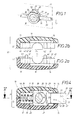
- the cord stopper comprises a housing 10 in plate form.
- the middle plate level 11 is indicated by dash-dotted lines in FIGS. 1 and 4, in which, in the invention, the cord 30 with its cord axis 53 according to FIG. 1 also runs.
- the housing has a circular outline 12 best seen in FIG. 3 and has an elongated, radially penetrating channel 13, which is used for the passage of the cord 30.
- the housing consists of two mutually identical housing halves 14 made of plastic with the profile shown in FIGS. 2a, 2b and 3.
- the channel 13 is divided in the two housing halves 14 into two longitudinal shells 15 of identical shape.
- the outlet openings 16 of the channel appear on the narrow sides of the plate 17.
- the plate wide surfaces 18, which run approximately parallel to the plane of the plate 11, are exposed and are light in the present case, as can be seen from FIGS. 2a and 2b arched and delimited by a circumferential decorative groove 19 relative to the edge regions of the housing 10.
- These plate wide surfaces 18 have the profile of caps, as are known per se for fastening parts of hard suitcaserdashery articles. For example, caps are used on the flanges of rivet fastening parts, which are provided with pictures, writing or decorations. Such caps are also often used for attaching company logos.
- the housing 10 occupies the most space-saving position. The diameter perpendicular to it protrudes transversely to the cord 30, but this only happens in the central housing area 52, from where the dimensions, towards the channel outlet openings 16, rapidly approach the cord 30 again radially. This exposed central area 52 of the housing is currently being used by the invention in order to place the slide 20 there and thus to make it easy for the operator to find and operate. There, at 52, the housing 10 has the greatest radial distance 54 compared to the cord axis 53 that can be seen in FIG. 1.
- the slide 20 has the shape best seen in FIGS. 4 and 5, which can be divided into a working section 21 arranged essentially in the interior of the housing and into a handle 22 projecting from the housing 10 at least with its end piece.
- Both components 21, 22 of the Sliders 20 have the shape of a flattened cuboid, which, viewed in cross section, gives them a rectangular profile, the longitudinal extension 23 or 24 of which is illustrated in FIGS. 4 and 5.
- a comparison of these two components 21, 22 shows that their longitudinal extensions 23, 24 are oriented at right angles to one another; While the longitudinal extension 23 in the working section 21 extends transverse to the plate plane 11 when the slide 20 is installed in the housing 10, the longitudinal extension 24 extends parallel to the plate plane 11 in the handle 22.
- a guideway 31 which is adapted to the dimensions of the cuboid-shaped working section 21 and is half integrated in the two housing halves 14.
- a compression spring 32 engages on the slider inner end 26, which strives to push the outer end 27 of the slider 20 out of the housing 10 in the direction of the arrow 28 at the point 52 radially farthest from the cord axis 53.
- This extension movement 28 is limited by an inner stop shoulder 29 against which the upper square edge of the working section 21 can come to rest in extreme cases. However, this does not occur in the use case of the cord stopper according to the invention for the following reason.
- the working section 21 has a through hole 33, the inside width 34 of which is adapted to the opening cross section of the channel 13.
- the through hole 33 comes to lie flush with the channel 13 when the handle 22 is pressed in by exerting pressure on its outer end 27 in the sense of the insertion arrow 28 ', likewise indicated in FIG. 4.
- the slide outer end 27 of the handle 22 is curved instead of just arched.
- the compression spring 32 is compressed, which is positioned by an integrally formed pin 35 on the slide inner end 26.
- the compression spring 32 is located in a chamber 36 of the housing 10, which is also arranged in half in each of the two housing halves 14 and adjoins the inner end of the already mentioned guideway 31.
- the cord 30 can be easily threaded through the channel 13 and the through hole 33 aligned therewith.
- the housing 10 is also longitudinally displaceable in the sense of the double arrow 37 indicated in FIG. 1.
- the cord stopper can now be fixed immovably on the cord 30 by releasing the handle 22 of the slider 20.
- the spring 32 presses the slide 20 in the direction of the extension arrow 28 transversely to the cord and brings its through hole 33 into an offset to the channel 13, which leads to a pinch 39 best seen in FIG. 5. So that the housing 10 is locked to the cord 30.
- the two housing halves 14 are designed to be mirror images of each other identically and have complementary connecting elements 40 to 43 in the form of pins 40, 41 on the one hand and receptacles 42, 43 on the other. As best shown in FIG. 3, these are arranged symmetrically with respect to the longitudinal center determined by the guideway 31 net.
- These connecting elements 40 to 43 are initially located in the four sectors, which are separated from the circular structure of the housing half 14 by the longitudinal channel shells 15 lying at right angles to one another on the one hand and the halves of the guideway 31 and the chamber 36 on the other hand.
- the connecting elements 40 to 43 are arranged in the contact surfaces 45 defining the parting line 44. As is clear from FIGS.
- the pin 40 proceeds from this contact surface 45 on the parting joint side, while the other pin 41 located on the other side of the channel shell 15 is lowered with a partial length in a housing recess 46.
- both the receptacles 42, 43 arranged opposite the pegs 40, 41 are of identical design, the receptacle 43 associated with the longer peg 41 is produced from the inside of a sleeve 47, which is arranged in a housing recess 48. As a result, the elasticity of the material when the long pin 41 is engaged in the receiving sleeve 47 is improved.
- the contact surface 45 of the housing half 14 is equipped in the edge region of its circular outline 12 with ribs 49, 50, which act as welding aids when the two housing halves 14 are joined together. These are energy direction transmitters that concentrate the sound direction when welding with ultrasound.
- the rib and the diametrically opposite abutment surface of the counter-housing half evaporate.
- the softened material serves as an adhesive which hardens after cooling and ensures that the two housing halves 14 are held together.
- Such a material bridge 51 could be designed as an articulated hinge, but it is easier and cheaper to use a film hinge for this.
- the two housing halves 14 are then simply assembled by a folding movement.
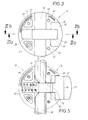
- FIGS. 6 and 7 show a plate-shaped housing 10 'which is produced in one piece from plastic by injection molding and which will hereinafter be referred to as "plate housing” for short. It comprises in its interior two intersecting chambers, namely the longitudinally running channel 13 which serves to hold the previously described cord 30 and a transverse cavity 55 which opens out on one narrow side 56 of the plate housing 10 '.
- the cave 55 is stepped in itself and initially has a channel 57 which opens out on the narrow side 56 and narrows in the cave bottom via an inclined surface 58 into the chamber 36 already described above.
- the plate narrow sides 56 are, apart from rounded edges 65 on the circular outline, essentially flat.
- This channel 57 widens in the area of the cave opening in a mirror image of one another with respect to a cross-sectional plane perpendicular to the channel 13 into two mutually opposite extensions 59 which determine a rectangular cross section and lie in the area of the cave opening.
- the channel 57 also has a rectangular cross section, which is perpendicular to the cross section determined by the two extensions 59.
- the cave walls 60 in the region of the channel 57 are equipped with two opposing cams 61, which are dome-shaped here and have a distance 62 from one another which is coordinated with the slide 20 ′ to be described in more detail.
- the plate housing 10 ' also has a circular outline here, which determines its narrow sides.
- the wide plate surfaces are designed here as spherical surfaces 63, preferably with a spherical radius that is equal to one another, but which has a very flat curvature.
- the radius of the sphere exceeds the given dimensions of the plate housing 10 'by a multiple, namely somewhat more than three times the mentioned circular diameter of the plate housing 10'.
- These spherical surfaces 63 have a curvature which corresponds to the concave curvature on the inner surface of caps, as are used for fastening parts of hard suitcaserdashery articles. These can therefore be attached to the spherical surfaces 63 in an interchangeable manner. Both spherical surfaces 63 are surrounded by substantially flat frame parts 66, which also determine the width of the plate in the form of an edge zone. Between the frame parts 66 and the spherical surfaces 63 there is a groove 19 already mentioned, which is preferably aligned with the outline of the caps to be mounted.
- the slide 20 'belonging to the above-described plate housing 10' is illustrated.
- it consists of two pieces angular plate sections 67, 68, which, however, in contrast to the described spherical-like crowning of the plate wide surfaces in the plate housing 10 ', have flat plate surfaces 69 and 70, respectively.
- the two plate sections 67, 68 only touch one place on their narrow sides 71 due to their one-piece construction and are perpendicular to one another with their plate course.
- One plate section 68 has the passage hole 33 for the cord already described and thus functions as the working section of this slide 20 'already described in the first exemplary embodiment after it has been installed in the plate housing 10'.
- this plate section 68 In the interior of the through hole 33 there is a tooth 77 which penetrates into the cord when in use.
- the outline of this plate section 68 is non-uniform, however, and includes inner and outer run-up slopes 72, 73 which are mirror-symmetrical to one another in the middle of the through hole 33 and which, as shown in FIG. 8, give this plate section 68 the appearance of a hexagon nut.
- the one mirror plane determines the mirror axis 74 indicated by dash-dotted lines, which continues in the adjacent plate section 67, even if this is mirror-symmetrical in a rectangular manner.
- This adjacent plate section 67 serves as a handle and protrudes from the plate housing 10 'after it has been installed.
- the slide 20 ' is mounted in the plate housing 10' via the cavity opening.
- the above-described channel 57 serves to accommodate the working section 68, which is why the cavity walls 60 produce the relevant guideway both during assembly and afterwards.
- the two diametrically opposite intermediate zones 75 which are located between the above-described run-on slopes 72, 73 on both sides, are slidably guided on this track.
- the two cams 61 described above also become effective.
- the distance 62 between them is narrower than the outer dimension 76 of the plate section 68 determined by the two intermediate zones 75 by approximately 1/10 mm.
- the two opposing cams 61 therefore run onto the two inner run-up bevels 72 and lead to elastic deformation until the cams 61, beyond the two intermediate zones 75, snap back behind the outer run-up bevels 73. Thereafter, the slider 20 'is sufficiently secured by its inserted plate section 68 located behind the cams 61.
- the compression spring located in the bottom of the cavity in the chamber 36 does not have sufficient force to separate the slide 20 'from the housing 10' after this assembly. Disassembly would be possible because of the oppositely inclined outer run-on bevels 73 on the opposite side. If this is not desired, appropriate undercuts could be used here.
- Suitable, non-uniform profiles of the cams 61 could make disassembly difficult or even impossible if this should be desired.
- the undesired disassembly is not to be feared anyway because the threaded cord, as can be seen in FIG. 5 of the previous exemplary embodiment, connects the two components 10 ′, 20 ′ to one another.
- the plate section 67 acting as a handle is located in the region of the channel extensions 59 described and is guided there.
- the indentation depth of the slide 20 ' is determined on the section narrow side 71 by the protruding edges between the two plate sections 67, 68, which abut the bottom of the extension 59.
- the above-described inclined surfaces 58 in the base of the cave allow the mounted slide 20 'to be pressed in undisturbed and can interact with the inner run-up bevels 72 of its plate section 68.
Landscapes
- Engineering & Computer Science (AREA)
- General Engineering & Computer Science (AREA)
- Structural Engineering (AREA)
- Mechanical Engineering (AREA)
- Architecture (AREA)
- Civil Engineering (AREA)
- Buckles (AREA)
Applications Claiming Priority (4)
| Application Number | Priority Date | Filing Date | Title |
|---|---|---|---|
| DE9015771U | 1990-11-17 | ||
| DE9015771U DE9015771U1 (de) | 1990-11-17 | 1990-11-17 | Kordelstopper mit wenigstens einer durchziehbaren Kordel und mit einer Kordel-Arretierung |
| DE9103708U | 1991-03-26 | ||
| DE9103708U DE9103708U1 (de) | 1990-11-17 | 1991-03-26 | Kordelstopper mit wenigstens einer durchziehbaren Kordel und mit einer Kordel-Arretierung |
Publications (2)
| Publication Number | Publication Date |
|---|---|
| EP0486779A2 true EP0486779A2 (fr) | 1992-05-27 |
| EP0486779A3 EP0486779A3 (en) | 1992-11-19 |
Family
ID=25957439
Family Applications (1)
| Application Number | Title | Priority Date | Filing Date |
|---|---|---|---|
| EP19910115056 Withdrawn EP0486779A3 (en) | 1990-11-17 | 1991-09-06 | Locking device for cord with at least one going-through cord and with a cord clamp |
Country Status (2)
| Country | Link |
|---|---|
| EP (1) | EP0486779A3 (fr) |
| DE (1) | DE9103708U1 (fr) |
Cited By (2)
| Publication number | Priority date | Publication date | Assignee | Title |
|---|---|---|---|---|
| EP1018609A1 (fr) * | 1998-12-28 | 2000-07-12 | Ykk Corporation | Dispositif de verrouillage de ruban |
| DE10150339C1 (de) * | 2001-10-15 | 2002-08-29 | Hp Products & Services Hildega | Schnurklemme |
Families Citing this family (2)
| Publication number | Priority date | Publication date | Assignee | Title |
|---|---|---|---|---|
| DE9103708U1 (de) * | 1990-11-17 | 1991-06-27 | William Prym-Werke GmbH & Co KG, 5190 Stolberg | Kordelstopper mit wenigstens einer durchziehbaren Kordel und mit einer Kordel-Arretierung |
| JP5687850B2 (ja) * | 2010-06-02 | 2015-03-25 | 株式会社ニフコ | コードロック |
Family Cites Families (7)
| Publication number | Priority date | Publication date | Assignee | Title |
|---|---|---|---|---|
| US3074135A (en) * | 1960-04-12 | 1963-01-22 | John A Di Lorenzo | Releasible lace fastener device |
| US3122805A (en) * | 1962-03-27 | 1964-03-03 | Albert S Hakim | Bow knot fastener |
| DE3535623A1 (de) * | 1985-10-05 | 1987-04-09 | Gernot Walter Reichel | Klemmverschluss |
| US4680835A (en) * | 1986-04-30 | 1987-07-21 | Horng Sheng Chorng | Sport shoe lacing device |
| JPS63272302A (ja) * | 1987-04-30 | 1988-11-09 | モリト株式会社 | 紐の調節固定具及びその製造方法 |
| DE9015771U1 (de) * | 1990-11-17 | 1991-02-07 | William Prym-Werke GmbH & Co KG, 5190 Stolberg | Kordelstopper mit wenigstens einer durchziehbaren Kordel und mit einer Kordel-Arretierung |
| DE9103708U1 (de) * | 1990-11-17 | 1991-06-27 | William Prym-Werke GmbH & Co KG, 5190 Stolberg | Kordelstopper mit wenigstens einer durchziehbaren Kordel und mit einer Kordel-Arretierung |
-
1991
- 1991-03-26 DE DE9103708U patent/DE9103708U1/de not_active Expired - Lifetime
- 1991-09-06 EP EP19910115056 patent/EP0486779A3/de not_active Withdrawn
Cited By (3)
| Publication number | Priority date | Publication date | Assignee | Title |
|---|---|---|---|---|
| EP1018609A1 (fr) * | 1998-12-28 | 2000-07-12 | Ykk Corporation | Dispositif de verrouillage de ruban |
| US6339865B1 (en) | 1998-12-28 | 2002-01-22 | Ykk Corporation | Cord fastener |
| DE10150339C1 (de) * | 2001-10-15 | 2002-08-29 | Hp Products & Services Hildega | Schnurklemme |
Also Published As
| Publication number | Publication date |
|---|---|
| DE9103708U1 (de) | 1991-06-27 |
| EP0486779A3 (en) | 1992-11-19 |
Similar Documents
| Publication | Publication Date | Title |
|---|---|---|
| DE69804077T2 (de) | Befestigungsmittel für lösbare Verbindungen von Platten | |
| EP0266500B1 (fr) | Moyens de connexion à recouvrement | |
| EP3405062B1 (fr) | Dispositif de fermeture permettant de relier deux pièces de manière détachable | |
| DE3843096C2 (de) | Befestigungseinrichtung für Verkleidungen | |
| EP0862002B1 (fr) | Système de raccordement de deux corps d'ensemble traversé par un écoulement de fluides | |
| EP1898105A2 (fr) | Fermeture rapide destinée à la liaison de deux composants | |
| DE3515303C1 (de) | Kugelgelenk,insbesondere fuer Kraftfahrzeuge,sowie Montagevorrichtung hierfuer | |
| DE19517010A1 (de) | Druckknopfverschluß | |
| AT389805B (de) | Reissverschluss | |
| DE2906288C2 (de) | Anbauteil zum Anschluß an eine Wandung, insbesondere Griff oder Armlehne zum Anschluß an ein Karosserieteil eines Kraftfahrzeuges | |
| DE19506106C2 (de) | Beschlag für Fenster, Türen od. dgl. | |
| CH451601A (de) | Befestigungsmittel | |
| EP2156060B1 (fr) | Dispositif de fixation permettant d'assembler un profilé et un contre-profilé de façon libérable | |
| EP0486779A2 (fr) | Dispositif de blocage de corde avec au moins une corde traversante et un dispositif d'arrêt de corde | |
| DE1708259B1 (de) | Tuerscharnier,insbesondere fuer Kraftfahrzeugtueren | |
| DE2550186A1 (de) | Notoeffnungsschieber fuer reissverschluesse | |
| WO2016110417A1 (fr) | Raccord de liaison | |
| DE2104150C2 (de) | Druckknopfähnlicher Verschluß | |
| EP0791759A1 (fr) | Boulon à connexion rapide | |
| DE4323673C2 (de) | Schmuckstückverschluß | |
| DE4137418C2 (de) | Druckknopf | |
| DE69612850T2 (de) | Verbindung mit schneller befestigung zum beispiel für einen schalter | |
| DE10027896A1 (de) | Vorrichtung zur lösbaren Halterung von wenigstens zwei Flächenelementen und deren Verwendung | |
| DE19834038A1 (de) | Treibstangenbeschlag mit Eckumlenkung | |
| DE2002631B1 (de) | Rahmen fuer Fenster,Tueren od.dgl. |
Legal Events
| Date | Code | Title | Description |
|---|---|---|---|
| PUAI | Public reference made under article 153(3) epc to a published international application that has entered the european phase |
Free format text: ORIGINAL CODE: 0009012 |
|
| AK | Designated contracting states |
Kind code of ref document: A2 Designated state(s): AT BE DE DK ES FR GB IT NL |
|
| PUAL | Search report despatched |
Free format text: ORIGINAL CODE: 0009013 |
|
| AK | Designated contracting states |
Kind code of ref document: A3 Designated state(s): AT BE DE DK ES FR GB IT NL |
|
| STAA | Information on the status of an ep patent application or granted ep patent |
Free format text: STATUS: THE APPLICATION HAS BEEN WITHDRAWN |
|
| 18W | Application withdrawn |
Withdrawal date: 19930223 |
|
| R18W | Application withdrawn (corrected) |
Effective date: 19930222 |