EP3403880B1 - Dispositif d'éclairage - Google Patents
Dispositif d'éclairage Download PDFInfo
- Publication number
- EP3403880B1 EP3403880B1 EP17774188.1A EP17774188A EP3403880B1 EP 3403880 B1 EP3403880 B1 EP 3403880B1 EP 17774188 A EP17774188 A EP 17774188A EP 3403880 B1 EP3403880 B1 EP 3403880B1
- Authority
- EP
- European Patent Office
- Prior art keywords
- lens
- substrate
- outer lens
- light
- housing
- Prior art date
- Legal status (The legal status is an assumption and is not a legal conclusion. Google has not performed a legal analysis and makes no representation as to the accuracy of the status listed.)
- Active
Links
- 239000000758 substrate Substances 0.000 claims description 107
- 238000005192 partition Methods 0.000 claims description 12
- 230000002093 peripheral effect Effects 0.000 description 11
- 238000002955 isolation Methods 0.000 description 4
- 239000011347 resin Substances 0.000 description 3
- 229920005989 resin Polymers 0.000 description 3
- 230000001629 suppression Effects 0.000 description 3
- 230000017525 heat dissipation Effects 0.000 description 2
- 238000005286 illumination Methods 0.000 description 2
- 238000007789 sealing Methods 0.000 description 2
- 230000000694 effects Effects 0.000 description 1
- 230000020169 heat generation Effects 0.000 description 1
- 238000003780 insertion Methods 0.000 description 1
- 230000037431 insertion Effects 0.000 description 1
Images


Classifications
-
- F—MECHANICAL ENGINEERING; LIGHTING; HEATING; WEAPONS; BLASTING
- F21—LIGHTING
- F21V—FUNCTIONAL FEATURES OR DETAILS OF LIGHTING DEVICES OR SYSTEMS THEREOF; STRUCTURAL COMBINATIONS OF LIGHTING DEVICES WITH OTHER ARTICLES, NOT OTHERWISE PROVIDED FOR
- F21V29/00—Protecting lighting devices from thermal damage; Cooling or heating arrangements specially adapted for lighting devices or systems
- F21V29/10—Arrangement of heat-generating components to reduce thermal damage, e.g. by distancing heat-generating components from other components to be protected
-
- B—PERFORMING OPERATIONS; TRANSPORTING
- B60—VEHICLES IN GENERAL
- B60Q—ARRANGEMENT OF SIGNALLING OR LIGHTING DEVICES, THE MOUNTING OR SUPPORTING THEREOF OR CIRCUITS THEREFOR, FOR VEHICLES IN GENERAL
- B60Q1/00—Arrangement of optical signalling or lighting devices, the mounting or supporting thereof or circuits therefor
- B60Q1/0029—Spatial arrangement
- B60Q1/0041—Spatial arrangement of several lamps in relation to each other
- B60Q1/0058—Stacked, i.e. one lamp located behind the other in the optical axis direction
-
- B—PERFORMING OPERATIONS; TRANSPORTING
- B60—VEHICLES IN GENERAL
- B60Q—ARRANGEMENT OF SIGNALLING OR LIGHTING DEVICES, THE MOUNTING OR SUPPORTING THEREOF OR CIRCUITS THEREFOR, FOR VEHICLES IN GENERAL
- B60Q1/00—Arrangement of optical signalling or lighting devices, the mounting or supporting thereof or circuits therefor
- B60Q1/26—Arrangement of optical signalling or lighting devices, the mounting or supporting thereof or circuits therefor the devices being primarily intended to indicate the vehicle, or parts thereof, or to give signals, to other traffic
- B60Q1/2607—Arrangement of optical signalling or lighting devices, the mounting or supporting thereof or circuits therefor the devices being primarily intended to indicate the vehicle, or parts thereof, or to give signals, to other traffic comprising at least two indicating lamps
-
- B—PERFORMING OPERATIONS; TRANSPORTING
- B60—VEHICLES IN GENERAL
- B60Q—ARRANGEMENT OF SIGNALLING OR LIGHTING DEVICES, THE MOUNTING OR SUPPORTING THEREOF OR CIRCUITS THEREFOR, FOR VEHICLES IN GENERAL
- B60Q1/00—Arrangement of optical signalling or lighting devices, the mounting or supporting thereof or circuits therefor
- B60Q1/26—Arrangement of optical signalling or lighting devices, the mounting or supporting thereof or circuits therefor the devices being primarily intended to indicate the vehicle, or parts thereof, or to give signals, to other traffic
- B60Q1/2696—Mounting of devices using LEDs
-
- B—PERFORMING OPERATIONS; TRANSPORTING
- B60—VEHICLES IN GENERAL
- B60Q—ARRANGEMENT OF SIGNALLING OR LIGHTING DEVICES, THE MOUNTING OR SUPPORTING THEREOF OR CIRCUITS THEREFOR, FOR VEHICLES IN GENERAL
- B60Q1/00—Arrangement of optical signalling or lighting devices, the mounting or supporting thereof or circuits therefor
- B60Q1/26—Arrangement of optical signalling or lighting devices, the mounting or supporting thereof or circuits therefor the devices being primarily intended to indicate the vehicle, or parts thereof, or to give signals, to other traffic
- B60Q1/30—Arrangement of optical signalling or lighting devices, the mounting or supporting thereof or circuits therefor the devices being primarily intended to indicate the vehicle, or parts thereof, or to give signals, to other traffic for indicating rear of vehicle, e.g. by means of reflecting surfaces
-
- B—PERFORMING OPERATIONS; TRANSPORTING
- B60—VEHICLES IN GENERAL
- B60Q—ARRANGEMENT OF SIGNALLING OR LIGHTING DEVICES, THE MOUNTING OR SUPPORTING THEREOF OR CIRCUITS THEREFOR, FOR VEHICLES IN GENERAL
- B60Q1/00—Arrangement of optical signalling or lighting devices, the mounting or supporting thereof or circuits therefor
- B60Q1/26—Arrangement of optical signalling or lighting devices, the mounting or supporting thereof or circuits therefor the devices being primarily intended to indicate the vehicle, or parts thereof, or to give signals, to other traffic
- B60Q1/56—Arrangement of optical signalling or lighting devices, the mounting or supporting thereof or circuits therefor the devices being primarily intended to indicate the vehicle, or parts thereof, or to give signals, to other traffic for illuminating registrations or the like, e.g. for licence plates
-
- B—PERFORMING OPERATIONS; TRANSPORTING
- B62—LAND VEHICLES FOR TRAVELLING OTHERWISE THAN ON RAILS
- B62J—CYCLE SADDLES OR SEATS; AUXILIARY DEVICES OR ACCESSORIES SPECIALLY ADAPTED TO CYCLES AND NOT OTHERWISE PROVIDED FOR, e.g. ARTICLE CARRIERS OR CYCLE PROTECTORS
- B62J6/00—Arrangement of optical signalling or lighting devices on cycles; Mounting or supporting thereof; Circuits therefor
- B62J6/04—Rear lights
-
- F—MECHANICAL ENGINEERING; LIGHTING; HEATING; WEAPONS; BLASTING
- F21—LIGHTING
- F21S—NON-PORTABLE LIGHTING DEVICES; SYSTEMS THEREOF; VEHICLE LIGHTING DEVICES SPECIALLY ADAPTED FOR VEHICLE EXTERIORS
- F21S43/00—Signalling devices specially adapted for vehicle exteriors, e.g. brake lamps, direction indicator lights or reversing lights
- F21S43/10—Signalling devices specially adapted for vehicle exteriors, e.g. brake lamps, direction indicator lights or reversing lights characterised by the light source
- F21S43/13—Signalling devices specially adapted for vehicle exteriors, e.g. brake lamps, direction indicator lights or reversing lights characterised by the light source characterised by the type of light source
- F21S43/14—Light emitting diodes [LED]
-
- F—MECHANICAL ENGINEERING; LIGHTING; HEATING; WEAPONS; BLASTING
- F21—LIGHTING
- F21S—NON-PORTABLE LIGHTING DEVICES; SYSTEMS THEREOF; VEHICLE LIGHTING DEVICES SPECIALLY ADAPTED FOR VEHICLE EXTERIORS
- F21S43/00—Signalling devices specially adapted for vehicle exteriors, e.g. brake lamps, direction indicator lights or reversing lights
- F21S43/10—Signalling devices specially adapted for vehicle exteriors, e.g. brake lamps, direction indicator lights or reversing lights characterised by the light source
- F21S43/13—Signalling devices specially adapted for vehicle exteriors, e.g. brake lamps, direction indicator lights or reversing lights characterised by the light source characterised by the type of light source
- F21S43/15—Strips of light sources
-
- F—MECHANICAL ENGINEERING; LIGHTING; HEATING; WEAPONS; BLASTING
- F21—LIGHTING
- F21S—NON-PORTABLE LIGHTING DEVICES; SYSTEMS THEREOF; VEHICLE LIGHTING DEVICES SPECIALLY ADAPTED FOR VEHICLE EXTERIORS
- F21S43/00—Signalling devices specially adapted for vehicle exteriors, e.g. brake lamps, direction indicator lights or reversing lights
- F21S43/10—Signalling devices specially adapted for vehicle exteriors, e.g. brake lamps, direction indicator lights or reversing lights characterised by the light source
- F21S43/19—Attachment of light sources or lamp holders
- F21S43/195—Details of lamp holders, terminals or connectors
-
- F—MECHANICAL ENGINEERING; LIGHTING; HEATING; WEAPONS; BLASTING
- F21—LIGHTING
- F21S—NON-PORTABLE LIGHTING DEVICES; SYSTEMS THEREOF; VEHICLE LIGHTING DEVICES SPECIALLY ADAPTED FOR VEHICLE EXTERIORS
- F21S43/00—Signalling devices specially adapted for vehicle exteriors, e.g. brake lamps, direction indicator lights or reversing lights
- F21S43/20—Signalling devices specially adapted for vehicle exteriors, e.g. brake lamps, direction indicator lights or reversing lights characterised by refractors, transparent cover plates, light guides or filters
- F21S43/26—Refractors, transparent cover plates, light guides or filters not provided in groups F21S43/235 - F21S43/255
-
- F—MECHANICAL ENGINEERING; LIGHTING; HEATING; WEAPONS; BLASTING
- F21—LIGHTING
- F21S—NON-PORTABLE LIGHTING DEVICES; SYSTEMS THEREOF; VEHICLE LIGHTING DEVICES SPECIALLY ADAPTED FOR VEHICLE EXTERIORS
- F21S43/00—Signalling devices specially adapted for vehicle exteriors, e.g. brake lamps, direction indicator lights or reversing lights
- F21S43/30—Signalling devices specially adapted for vehicle exteriors, e.g. brake lamps, direction indicator lights or reversing lights characterised by reflectors
- F21S43/31—Optical layout thereof
-
- F—MECHANICAL ENGINEERING; LIGHTING; HEATING; WEAPONS; BLASTING
- F21—LIGHTING
- F21S—NON-PORTABLE LIGHTING DEVICES; SYSTEMS THEREOF; VEHICLE LIGHTING DEVICES SPECIALLY ADAPTED FOR VEHICLE EXTERIORS
- F21S43/00—Signalling devices specially adapted for vehicle exteriors, e.g. brake lamps, direction indicator lights or reversing lights
- F21S43/40—Signalling devices specially adapted for vehicle exteriors, e.g. brake lamps, direction indicator lights or reversing lights characterised by the combination of reflectors and refractors
-
- F—MECHANICAL ENGINEERING; LIGHTING; HEATING; WEAPONS; BLASTING
- F21—LIGHTING
- F21S—NON-PORTABLE LIGHTING DEVICES; SYSTEMS THEREOF; VEHICLE LIGHTING DEVICES SPECIALLY ADAPTED FOR VEHICLE EXTERIORS
- F21S43/00—Signalling devices specially adapted for vehicle exteriors, e.g. brake lamps, direction indicator lights or reversing lights
- F21S43/50—Signalling devices specially adapted for vehicle exteriors, e.g. brake lamps, direction indicator lights or reversing lights characterised by aesthetic components not otherwise provided for, e.g. decorative trim, partition walls or covers
-
- F—MECHANICAL ENGINEERING; LIGHTING; HEATING; WEAPONS; BLASTING
- F21—LIGHTING
- F21S—NON-PORTABLE LIGHTING DEVICES; SYSTEMS THEREOF; VEHICLE LIGHTING DEVICES SPECIALLY ADAPTED FOR VEHICLE EXTERIORS
- F21S45/00—Arrangements within vehicle lighting devices specially adapted for vehicle exteriors, for purposes other than emission or distribution of light
- F21S45/10—Protection of lighting devices
-
- F—MECHANICAL ENGINEERING; LIGHTING; HEATING; WEAPONS; BLASTING
- F21—LIGHTING
- F21V—FUNCTIONAL FEATURES OR DETAILS OF LIGHTING DEVICES OR SYSTEMS THEREOF; STRUCTURAL COMBINATIONS OF LIGHTING DEVICES WITH OTHER ARTICLES, NOT OTHERWISE PROVIDED FOR
- F21V19/00—Fastening of light sources or lamp holders
-
- F—MECHANICAL ENGINEERING; LIGHTING; HEATING; WEAPONS; BLASTING
- F21—LIGHTING
- F21V—FUNCTIONAL FEATURES OR DETAILS OF LIGHTING DEVICES OR SYSTEMS THEREOF; STRUCTURAL COMBINATIONS OF LIGHTING DEVICES WITH OTHER ARTICLES, NOT OTHERWISE PROVIDED FOR
- F21V23/00—Arrangement of electric circuit elements in or on lighting devices
- F21V23/003—Arrangement of electric circuit elements in or on lighting devices the elements being electronics drivers or controllers for operating the light source, e.g. for a LED array
- F21V23/004—Arrangement of electric circuit elements in or on lighting devices the elements being electronics drivers or controllers for operating the light source, e.g. for a LED array arranged on a substrate, e.g. a printed circuit board
- F21V23/006—Arrangement of electric circuit elements in or on lighting devices the elements being electronics drivers or controllers for operating the light source, e.g. for a LED array arranged on a substrate, e.g. a printed circuit board the substrate being distinct from the light source holder
-
- F—MECHANICAL ENGINEERING; LIGHTING; HEATING; WEAPONS; BLASTING
- F21—LIGHTING
- F21V—FUNCTIONAL FEATURES OR DETAILS OF LIGHTING DEVICES OR SYSTEMS THEREOF; STRUCTURAL COMBINATIONS OF LIGHTING DEVICES WITH OTHER ARTICLES, NOT OTHERWISE PROVIDED FOR
- F21V29/00—Protecting lighting devices from thermal damage; Cooling or heating arrangements specially adapted for lighting devices or systems
- F21V29/15—Thermal insulation
-
- F—MECHANICAL ENGINEERING; LIGHTING; HEATING; WEAPONS; BLASTING
- F21—LIGHTING
- F21W—INDEXING SCHEME ASSOCIATED WITH SUBCLASSES F21K, F21L, F21S and F21V, RELATING TO USES OR APPLICATIONS OF LIGHTING DEVICES OR SYSTEMS
- F21W2103/00—Exterior vehicle lighting devices for signalling purposes
- F21W2103/10—Position lights
-
- F—MECHANICAL ENGINEERING; LIGHTING; HEATING; WEAPONS; BLASTING
- F21—LIGHTING
- F21W—INDEXING SCHEME ASSOCIATED WITH SUBCLASSES F21K, F21L, F21S and F21V, RELATING TO USES OR APPLICATIONS OF LIGHTING DEVICES OR SYSTEMS
- F21W2103/00—Exterior vehicle lighting devices for signalling purposes
- F21W2103/50—Registration plate lights
-
- F—MECHANICAL ENGINEERING; LIGHTING; HEATING; WEAPONS; BLASTING
- F21—LIGHTING
- F21W—INDEXING SCHEME ASSOCIATED WITH SUBCLASSES F21K, F21L, F21S and F21V, RELATING TO USES OR APPLICATIONS OF LIGHTING DEVICES OR SYSTEMS
- F21W2107/00—Use or application of lighting devices on or in particular types of vehicles
- F21W2107/10—Use or application of lighting devices on or in particular types of vehicles for land vehicles
- F21W2107/13—Use or application of lighting devices on or in particular types of vehicles for land vehicles for cycles
- F21W2107/17—Use or application of lighting devices on or in particular types of vehicles for land vehicles for cycles for motorcycles
-
- F—MECHANICAL ENGINEERING; LIGHTING; HEATING; WEAPONS; BLASTING
- F21—LIGHTING
- F21Y—INDEXING SCHEME ASSOCIATED WITH SUBCLASSES F21K, F21L, F21S and F21V, RELATING TO THE FORM OR THE KIND OF THE LIGHT SOURCES OR OF THE COLOUR OF THE LIGHT EMITTED
- F21Y2107/00—Light sources with three-dimensionally disposed light-generating elements
- F21Y2107/60—Light sources with three-dimensionally disposed light-generating elements on stacked substrates
-
- F—MECHANICAL ENGINEERING; LIGHTING; HEATING; WEAPONS; BLASTING
- F21—LIGHTING
- F21Y—INDEXING SCHEME ASSOCIATED WITH SUBCLASSES F21K, F21L, F21S and F21V, RELATING TO THE FORM OR THE KIND OF THE LIGHT SOURCES OR OF THE COLOUR OF THE LIGHT EMITTED
- F21Y2115/00—Light-generating elements of semiconductor light sources
- F21Y2115/10—Light-emitting diodes [LED]
Definitions
- the present invention relates to a light device.
- EP 2 918 484 A1 discloses a light device for a vehicle.
- the light device is described to arrange a first base plate and a second base plate within a housing that is closed by a lens thereby establishing a compartment in which the rest of the components of the light device is arranged.
- Attached to the housing is a reflector being integrally formed with a column.
- the column supports the first base plate and the second base plate to which first and second light sources are attached.
- JP 2015 53 233 A describes a light device comprising a pillar arranged inside a globe and supporting a base.
- a lighting element, in particular an LED, is arranged on the base.
- an aspect of the present invention provides a light device comprising a light source (25, 26, 28), an electrical element (27) that turns on the light source (25, 26, 28), and substrates (15, 17, 19) on which the light source (25, 26, 28) and the electrical element (27) are disposed, a plurality of the substrates (15, 17, 19) are independently provided, and are disposed to be spaced from one another.
- the light device may include a column (16) to which the substrates (15, 17, 19) are fixed, and a partition portion (16b) that is fixed to the column (16), and is disposed between the plurality of substrates (15, 17, 19).
- the light device may include a housing (11) that supports the column (16), an outer lens (12) that, together with the housing (11), forms a housing portion (13) for housing the plurality of substrates (15, 17, 19), and an inner lens (18) that is provided inside the outer lens (12), and is disposed between the plurality of substrates (15, 17, 19) and supported by the column (16).
- the outer lens (12) may include a lens cut portion (12z) that is a part of the outer lens (12) and that has been subjected to lens cut processing
- the inner lens (18) may include a lens cut portion (18p) in a position that does not overlap with the lens cut portion (12z) of the outer lens (12) in a rear view.
- the outer lens (12) may be a tail lamp, and may include a light transmitting portion (12m) in a part of a bottom surface of the outer lens (12), the light transmitting portion (12m) transmitting light of the light source (28) to illuminate a license plate (50) attached to a rear portion of a vehicle body, and a boundary (11d2) between the light transmitting portion (12m) and a lower portion of the housing (11) may be located in front of an upper boundary (11d1) with respect to the vehicle body, the upper boundary (11d1) being provided between the outer lens (12) and the housing (11).
- the lens cut portion (12z) may be provided in a center portion of the outer lens (12), the lens cut portion (18p) may be provided in the inner lens (18) on both sides of the lens cut portion (12z) of the outer lens (12), and the substrate (19) disposed between the outer lens (12) and the inner lens (18) may be disposed on an inner side of a contour of the lens cut portion (12z) of the outer lens (12).
- the plurality of substrates are separately provided, which allows heat sources to be kept isolated so as to suppress the heat influence.
- the light device includes the column that supports the substrates, and a partition portion that is fixed to the column and disposed between the plurality of substrates, provision of the partition portion allows for further isolation of the heat sources and further suppression of the heat influence.
- the light device includes a housing that supports the column, an outer lens that, together with the housing, forms a housing portion for housing the plurality of substrates, and an inner lens that is provided inside the outer lens, and is disposed between the plurality of substrates and supported by the column, the inner lens can be utilized as a partition plate for the plurality of substrates, and isolation of the heat sources can be attained by the inner lens. In this way, the heat influence can be further suppressed.
- the inner lens also serves as a partition plate, and a support member becomes unnecessary as compared to the case where a special support member for the inner lens is additionally provided, which can reduce the number of components.
- the outer lens includes a lens cut portion that is a part of the outer lens and that has been subjected to lens cut processing
- the inner lens includes the lens cut portion in a position that does not overlap with the lens cut portion of the outer lens in a rear view
- the light emitted from the light device can be differentiated between the inner lens and the outer lens, thereby improving the visibility and giving the new impression.
- the outer lens is a tail lamp, and includes a light transmitting portion in a part of a bottom surface of the outer lens, the light transmitting portion transmitting the light of the light source to illuminate the license plate attached to a rear portion of the vehicle body, and a boundary between the light transmitting portion and a lower portion of the housing is located in front of an upper boundary with respect to the vehicle body, the upper boundary being provided between the outer lens and the housing. Consequently, an area in which the license plate can be illuminated is increased, which enables good illumination for the license plate.
- the lens cut portion is provided in the center portion of the outer lens, the lens cut portion is provided in the inner lens on both sides of the lens cut portion of the outer lens, and the substrate disposed between the outer lens and the inner lens is disposed on the inner side of the contour of the lens cut portion of the outer lens, which allows for miniaturization of the substrate and emission of the light from the light device with the light emitted from the light source to the lens cut portion of the outer lens being diffused, the light source being provided on the substrate disposed between the outer lens and the inner lens.
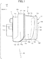
- Figure 1 is a left side view illustrating a tail light 10 that is attached to a rear end portion of the motorcycle.
- the tail light 10 includes a housing 11 that is provided at a front portion of the tail light 10, and an outer lens 12 that is attached to a rear edge of the housing 11.
- the tail light 10 is attached to a rear portion of a vehicle, and has a function of causing the existence of the vehicle to be recognized by a driver of another vehicle behind the vehicle.
- the tail light 10 may also serve as a stop light that is turned on when a brake is operated.
- the tail light 10 has a function of a license plate light that illuminates a license plate 50 disposed below the tail light 10.
- the housing 11 is made of resin, and includes a connector attaching portion 11a to which a connector connected to wire harnesses for energization is attached, the connector attaching portion 11a being provided in a front portion of the housing 11.
- the outer lens 12 is made of colorless and transparent or colored and transparent resin, and is formed in a substantially rectangular shape in a side view. In a lower portion of the outer lens 12, a bonding portion of the outer lens 12 with the housing 11 extends forward toward the lower side.
- a flange 12a is formed around substantially the entire circumference at a front portion of the outer lens 12 except for the lower portion of the outer lens 12.
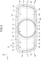
- Figure 2 is a rear view illustrating the tail light 10.
- the tail light 10 is formed so that both left and right ends of the tail light 10 are inclined to be located gradually closer to the center side in the vehicle width direction toward the lower side so as to have a substantially laterally long rectangular shape as a whole in a rear view.
- the outer lens 12 includes a circular-shaped rear center surface portion 12c that is located at a center in the vehicle width direction of a rear surface 12b of the outer lens 12, and a rear-left surface portion 12d and a rear-right surface portion 12e (see Figure 2 ) that are respectively located on a left side and a right side of the rear surface 12b with respect to the rear center surface portion 12c.
- the rear center surface portion 12c protrudes rearwardly beyond the rear-left surface portion 12d and the rear-right surface portion 12e.
- the rear center surface portion 12c is curved so as to protrude rearwardly.
- the rear-left surface portion 12d and the rear-right surface portion 12e are curved so as to protrude rearwardly, and are formed to be located gradually forward toward the lower side.
- Figure 3 is a plan view illustrating the tail light 10.
- the housing 11 includes a wide width portion 11b into which the outer lens 12 is inserted, the wide width portion 11b being provided in a rear portion of the housing 11, and a forward extending portion 11c that is formed so that a width of the forward extending portion 11c is smaller than that of the wide width portion 11b in the vehicle width direction, and that extends forward from and is integrally formed with the wide width portion 11b.
- the outer lens 12 includes a circumferential surface portion 12f that extends forward from a peripheral edge of the rear center surface portion 12c, and an top-left surface portion 12g and an top-right surface portion 12h that extend forward from an upper edge of the rear-left surface portion 12d and an upper edge of the rear-right surface portion 12e, respectively.
- the above-described circumferential surface portion 12f, top-left surface portion 12g, and top-right surface portion 12h forms a top surface 12A of the outer lens 12.
- the circumferential surface portion 12f includes a top surface protrusion 12j that extends to protrude forward so as to be sandwiched between the top-left surface portion 12g and the top-right surface portion 12h.
- the top surface protrusion 12j is curved to protrude upwardly, and protrudes upwardly beyond the top-left surface portion 12g and the top-right surface portion 12h.
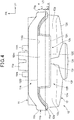
- Figure 4 is a bottom view illustrating the tail light 10.
- the wide width portion 11b of the housing 11 is formed so that a rear edge 11d of the wide width portion 11b is located gradually forward toward the lower side, and a bottom surface 11e of the wide width portion 11b extends linearly in the vehicle width direction.
- a distance in a front-rear direction between the rear edge 11d on a top surface 11f (see Figure 3 ) side and the left and right side surfaces 11g, 11h sides of the wide width portion 11b and the rear edge 11d on the bottom surface 11e side is denoted by a distance L1.
- the outer lens 12 is formed integrally with a trapezoidal light transmitting portion 12m at a center in the vehicle width direction of the bottom surface 12B of the outer lens 12.
- the light transmitting portion 12m is formed colorlessly and transparently, or white transparently so that a part of light in the tail light 10 is directed onto the license plate 50 (see Figure 1 ) through the light transmitting portion 12m.
- An edge thick portion 12n that is formed to be thick is formed around the light transmitting portion 12m to protrude downwardly beyond the light transmitting portion 12m and the bottom surface 12B.
- the outer lens 12 includes a bottom-left surface portion 12p and a bottom-right surface portion 12q that extend forward from a lower edge of the rear-left surface portion 12d and a lower edge of the rear-right surface portion 12e, respectively, and the bottom-left surface portion 12p and the bottom-right surface portion 12q extend to the flange 12a and the edge thick portion 12n.
- the above-described circumferential surface portion 12f, bottom-left surface portion 12p, and bottom-right surface portion 12q form the bottom surface 12B of the outer lens 12.
- the circumferential surface portion 12f of the outer lens 12 includes a bottom surface protrusion 12r that extends to protrude forward so as to be sandwiched between the bottom-left surface portion 12p and the bottom-right surface portion 12q.
- the bottom surface protrusion 12r is curved to protrude downwardly, and protrudes downwardly beyond the bottom-left surface portion 12p and the bottom-right surface portion 12q.
- Figure 5 is a cross-sectional view taken along line V-V of Figure 2 .
- Figure 6 is a cross-sectional view taken along line VI-VI of Figure 2 .
- the housing 11 is comprised of a flat bottom wall 11j, and a peripheral wall 11k that extends upwardly from a peripheral edge of the bottom wall 11j, the bottom wall 11j and the peripheral wall 11k being formed integrally with each other.
- a plurality of collars 14, a first substrate 15, a column 16, a second substrate 17 and an inner lens 18 are stacked on the bottom wall 11j of the housing 11, and the collars 14, the first substrate 15, the column 16, the second substrate 17 and the inner lens 18 are fixed to the bottom wall 11j with a plurality of screws 21.
- a third substrate 19 is fixed to a rear end of the column 16 with a screw 22.
- the cross sections of the above-described first substrate 15, second substrate 17, and third substrate 19 are indicated by cross-hatching.
- the screws 21 are inserted into the plurality of collars 14, the first substrate 15, the column 16, the second substrate 17, and the inner lens 18, so as to be screwed into corresponding front boss portions 11m that are formed to protrude forward from the bottom wall 11j.
- the wide width portion 11b is formed integrally with the peripheral wall 11k of the housing 11, and an annular fitting recess 11n is formed inside of the wide width portion 11b.
- An annular fitting portion 12s is inserted into the recess 11n through an annular sealing member 23 made of a rubber, the fitting portion 12s being formed in the peripheral edge of the outer lens 12. In this way, the sealability can be achieved in the bonding portion between the housing 11 and the outer lens 12 by the sealing member 23.
- the outer lens 12 includes a center wall 12t, a left rear wall 12u, a right rear wall 12v, left and right side walls 12w, 12w, a top wall 12x (also see Figure 3 ), and a bottom wall 12k (see Figure 4 ).
- the center wall 12t is provided with the rear center surface portion 12c and the circumferential surface portion 12f.
- the left rear wall 12u and the right rear wall 12v are disposed outwardly in the vehicle width direction of the center wall 12t.
- the left and right side walls 12w, 12w extend forward from side edges in the vehicle width direction of the left rear wall 12u and the right rear wall 12v, respectively.
- the top wall 12x includes the top surface 12A (see Figure 3 ).
- the bottom wall 12k includes the bottom surface (see Figure 4 ).
- the outer lens 12 is formed in a recess shape by the center wall 12t, the left rear wall 12u, the right rear wall 12v, the side walls 12w, 12w, the top wall 12x and the bottom wall 12k.
- a lens cut portion 12z that has been subjected to lens cut processing is provided in a front surface 12y of the center wall 12t.
- the lens cut portion 12z is a portion through which light emitted from a plurality of LED chips 26 is transmitted and that refracts the light in a predetermined direction.
- the light that has been transmitted through the center wall 12t including the lens cut portion 12z illuminates outside the tail light 10.
- the above-described housing 11 and outer lens 12 form a sealed housing portion 13.
- the first substrate 15, the second substrate 17, and the third substrate 19 are provided with a plurality of LED chips 25, 26 that serve as light sources of the tail light 10, and a plurality of electronic components 27 for turning on the plurality of LEDs 25, 26.
- the first substrate 15 is provided with the plurality of electronic components 27, the second substrate 17 is provided with the plurality of LED chips 25, and the third substrate 19 is provided with the plurality of LED chips 26.
- the first substrate 15 is formed in a flat plate shape, and is disposed at a distance from the bottom wall 11j of the housing 11 through the plurality of collars 14.
- the electronic components 27 are attached to a rear surface 15a of the first substrate 15. In this way, the first substrate 15 is separated from the bottom wall 11j to facilitate air flow generated around the first substrate 15 and thereby enhance the heat dissipation from the plurality of electronic components 27 that are attached to the first substrate 15.
- the column 16 is formed integrally of a plurality of cylindrical portions 16a, a connection plate portion 16b that connects the plurality of cylindrical portions 16a, and a column rear end portion 16c having a truncated cone shape that protrudes rearwardly from a center of the connection plate portion 16b and is tapered in a rearward direction.
- connection plate portion 16b is disposed between the first substrate 15 and the second substrate 17, and is a partition plate that is disposed at a distance from the fist substrate 15 and the second substrate 17.
- Such a connection plate portion 16b is provided to thereby facilitate air flow generated around the first substrate 15 and the second substrate 17, enhance the heat dissipation from the plurality of electronic components attached to the first substrate 15 and the plurality of LED chips 25 attached to the second substrate 17, and separate the heat of the first substrate 15 side from the heat of the second substrate 17 side.
- the second substrate 17 is formed in a flat plate shape to extend to the vicinity of the wide width portion 11b of the housing 11, and the plurality of LED chips 25 are attached to the left side and the right side of the rear surface 17a of the second substrate 17.
- a positioning hole 17b is formed outside in the vehicle width direction of the cylindrical portion 16a of the column 16, and a positioning piece 16d is inserted into the positioning hole 17b, the positioning piece 16d extending integrally rearwardly from the connection plate portion 16b of the column 16 so that the second substrate 17 is positioned with respect to the column 16.
- the inner lens 18 is made of colorless and transparent resin, and includes a cup-shaped inner lens center portion 18a that houses the third substrate 19, and an inner lens left portion 18b and an inner lens right portion 18c that are formed on a left side in the vehicle width direction and on a right side in the vehicle width direction with respect to the inner lens center portion 18a, respectively.
- the inner lens center portion 18a includes a bottom wall 18d that is fastened with the plurality of screws 21, and a peripheral wall 18e that extends rearwardly from the peripheral edge of the bottom wall 18d.
- the bottom wall 18d includes a through hole 18f that is provided in a center portion of the bottom wall 18d, and a plurality of recesses 18g that are provided around the through hole 18f.
- a head 21a of the screw 21 is inserted into the recess 18g.
- the third substrate 19 is disposed inside the peripheral wall 18e.
- Each of the inner lens left portion 18b and the inner lens right portion 18c of the inner lens 18 integrally includes a rear wall 18h that extends outwardly in the vehicle width direction from the peripheral wall 18e of the inner lens center portion 18a, a side wall 18j that extends forward from an edge outside in the vehicle width direction of the rear wall 18h, and a top wall 18k (see Figure 5 ) and a bottom wall that extend forward from the upper edge and the lower edge of the rear wall 18h, respectively.
- Each of the inner lens left portion 18b and the inner lens right portion 18c is a recessed portion that is surrounded by the above-described peripheral wall 18e, rear wall 18h, side wall 18j, top wall 18k and bottom wall.
- a lens cut portion 18p that has been subjected to lens cut processing is provided in a front surface 18n of the rear wall 18h.
- the lens cut portion 18p provided in each of the inner lens left portion 18b and the inner lens right portion 18c is provided in a position that does not overlap with the lens cut portion 12z of the outer lens 12.
- the left and right lens cut portions 18p, 18p each are a portion through which light emitted from the plurality of LED chips 25 is transmitted and that refracts the light in a predetermined direction.
- the light that has been transmitted through the rear walls 18h, 18h including the left and right lens cut portions 18p, 18p is further transmitted through the left rear wall 12u and the right rear wall 12v of the outer lens 12, and illuminates outside.
- the third substrate 19 is provided with the plurality of LED chips 26 in a rear surface 19a of the third substrate 19, and a screw 22 is inserted into a screw insertion hole 19b that is formed at a center of the third substrate 19, so that the third substrate 19 is fastened to the column rear end portion 16c of the column 16 with the screw 22.
- An outer shape of the third substrate 19 is smaller than that of the lens cut portion 12z, so that a contour of the third substrate 19 is disposed inside the contour of the lens cut portion 12z of the outer lens 12 in a rear view.
- connection plate portion 16b of the column 16 is formed integrally with a reflector 16e that faces downward, and is concavely curved below the connection plate portion 16b.
- the light transmitting portion 12m (see Figure 4 ) of the outer lens 12 is disposed below the reflector 16e.
- a plurality of LED chips 28 are attached to a center portion of a front surface 17c of the second substrate 17.
- the LED chip 28 is connected to the electronic component 27, to be turned on by the electronic component 27.
- the light emitted from the plurality of LED chips 28 is directed toward the lower side by the reflector 16e, and transmits through the light transmitting portion 12m to illuminate the license plate.
- Each of the above-described plurality of LED chips 25, 26, 28 is connected to the electronic component 27 through a wire 31.
- the tail light 10 serving as a light device that includes the LED chips 25, 26, 28 serving as light sources, the electronic components 27 serving as electrical elements to turn on the LED chips 25, 26, 28, and the first substrate 15, the second substrate 17, and the third substrate 19 on which the LED chips 25, 26, 28 and the electronic components 27 are disposed
- a plurality of the first substrate 15, the second substrate 17, and the third substrate 19 are independently provided, and are disposed to be spaced from one another.
- the plurality of the first substrate 15, the second substrate 17, and the third substrate 19 are separately located, which allows heat sources (i.e., LED chips 25, 26, 28) to be kept isolated so as to suppress the heat influence.
- the first substrate 15, the second substrate 17, and the third substrate 19 are disposed spaced from one another, which can facilitate air flow generated around the first substrate 15, the second substrate 17, and the third substrate 19, and lead to further suppression of the heat influence due to heat generation of the LED chips 25, 26, 28.
- connection plate portion 16b is fixed to the column 16, and serves as a partition portion disposed between the first substrate 15 and the second substrate 17, provision of the connection plate portion 16b allows for further isolation of heat sources and further suppression of the heat influence.
- the tail light 10 includes the housing 11 that supports the column 16, the outer lens 12 that, together with the housing 11, forms the housing portion 13 for housing the first substrate 15, the second substrate 17, and the third substrate 19, and the inner lens 18 that is provided inside the outer lens 12, and is disposed between the second substrate 17 and the third substrate 19 and supported by the column 16, the inner lens 18 can be utilized as a partition plate for the first substrate 15, the second substrate 17, and the third substrate 19, and isolation of the heat sources can be attained by the inner lens 18. In this way, the heat influence can be further suppressed.
- the inner lens also serves as a partition plate, and a support member becomes unnecessary as compared to the case where a special support member for the inner lens 18 is additionally provided, which can reduce the number of components and the cost of the tail light 10.
- the outer lens 12 includes the lens cut portion 12z that is a part of the outer lens 12 and that has been subjected to lens cut processing
- the inner lens 18 includes the lens cut portions 18p in a position that does not overlap with the lens cut portion 12z of the outer lens 12 in a rear view
- the light emitted from the tail light 10 can be differentiated between the inner lens 18 and the outer lens 12, thereby improving the visibility and giving the new impression.
- the outer lens 12 is a tail lamp, and includes the light transmitting portion 12m in a part of the bottom surface of the outer lens 12, the light transmitting portion 12m transmitting the light of the LED chips 28 to illuminate the license plate 50 (see Figure 1 ) attached to a rear portion of the vehicle body, and a rear edge 11d2 as a boundary between the light transmitting portion 12m and a lower portion of the housing 11 is located in front of a rear edge 11d1 with respect to the vehicle body, the rear edge 11d1 serving as an upper boundary between the outer lens 12 and the housing 11. Consequently, an area in which the license plate 50 can be illuminated is increased, which enables good illumination for the license plate 50.
- the lens cut portion 12z is provided in the center portion of the outer lens 12
- the lens cut portions 18p are provided in the inner lens 18 on both sides of the lens cut portion 12z of the outer lens 12
- the third substrate 19 disposed between the outer lens 12 and the inner lens 18 is disposed on the inner side of the contour of the lens cut portion 12z of the outer lens 12, which allows for miniaturization of the third substrate 19 and emission of the light from the tail light 10 with the light emitted from the LED chips 26 to the lens cut portion 12z of the outer lens 12 being diffused, the LED chips 26 being provided on the third substrate 19 disposed between the outer lens 12 and the inner lens 18. In this way, the visibility of the tail light 10 from persons behind the vehicle can be improved.
- the light transmitting portion 12m is formed integrally with the bottom surface 12B of the outer lens 12, but the present invention is not limited to this embodiment, and a light transmitting portion provided separately from the outer lens may be attached to the bottom of the outer lens.
- a platelike light transmitting portion may be formed integrally with the lower portion of the reflector 16e of the column 16, or a separate light transmitting portion may be attached to the lower portion of the reflector 16e.
- connection plate portion 16b is formed integrally with the column 16, but the present invention is not limited to this embodiment, and a connection plate portion (partition portion) separate from a column may be attached to the column 16.
Landscapes
- Engineering & Computer Science (AREA)
- General Engineering & Computer Science (AREA)
- Mechanical Engineering (AREA)
- Microelectronics & Electronic Packaging (AREA)
- Physics & Mathematics (AREA)
- Optics & Photonics (AREA)
- Non-Portable Lighting Devices Or Systems Thereof (AREA)
- Lighting Device Outwards From Vehicle And Optical Signal (AREA)
- Fastening Of Light Sources Or Lamp Holders (AREA)
Claims (4)
- Dispositif de lumière, comprenant :une source de lumière (25, 26, 28) ;un élément électrique (27) qui active la source de lumière (25, 26, 28) ;des substrats (15, 17, 19) sur lesquels la source de lumière (25, 26, 28) et l'élément électrique (27) sont disposés, une pluralité des substrats (15, 17, 19) étant prévus indépendamment, et étant disposés pour être espacés les uns des autres ;une colonne (16) sur laquelle sont fixés les substrats (15, 17, 19) ;une portion de séparation (16b) qui est fixée à la colonne (16), et est disposée entre la pluralité de substrats (15, 17, 19) ;un logement (11) qui supporte la colonne (16) ;une lentille extérieure (12) qui, conjointement avec le logement (11), forme une portion de logement (13) pour loger la pluralité de substrats (15, 17, 19) ; et caractérisé parune lentille intérieure (18) qui est prévue à l'intérieur de la lentille extérieure (12), et est disposée entre la pluralité de substrats (15, 17, 19) et supportée par la colonne (16).
- Dispositif de lumière selon la revendication 1, dans lequel
la lentille extérieure (12) comporte une portion de découpe de lentille (12z) qui fait partie de la lentille extérieure (12) et qui a été soumise à un traitement de découpe de lentille, et la lentille intérieure (18) comporte une portion de découpe de lentille (18p) dans une position qui ne chevauche pas la portion de découpe de lentille (12z) de la lentille extérieure (12) dans une vue arrière. - Dispositif de lumière selon la revendication 1 ou 2, dans lequel
la lentille extérieure (12) est un feu arrière, et comporte une portion de transmission de lumière (12m) dans une partie d'une surface basse de la lentille extérieure (12), la portion de transmission de lumière (12m) transmettant de la lumière de la source de lumière (28) pour illuminer une plaque d'immatriculation (50) attachée à une portion arrière d'une carrosserie de véhicule, et
une limite (11d2) entre la portion de transmission de lumière (12m) et une portion inférieure du logement (11) est située devant une limite supérieure (11d1) par rapport à la carrosserie de véhicule, la limite supérieure (11d1) étant prévue entre la lentille extérieure (12) et le logement (11). - Dispositif de lumière selon la revendication 2 ou 3, dans lequel
dans une vue arrière, la portion de découpe de lentille (12z) est prévue dans une portion centrale de la lentille extérieure (12),
la portion de découpe de lentille (18p) est prévue dans la lentille intérieure (18) sur les deux côtés de la portion de découpe de lentille (12z) de la lentille extérieure (12), et
le substrat (19) disposé entre la lentille extérieure (12) et la lentille intérieure (18) est disposé sur un côté intérieur d'un contour de la portion de découpe de lentille (12z) de la lentille extérieure (12).
Applications Claiming Priority (2)
| Application Number | Priority Date | Filing Date | Title |
|---|---|---|---|
| JP2016066502A JP6758874B2 (ja) | 2016-03-29 | 2016-03-29 | 灯火装置 |
| PCT/JP2017/009612 WO2017169643A1 (fr) | 2016-03-29 | 2017-03-09 | Dispositif d'éclairage |
Publications (3)
| Publication Number | Publication Date |
|---|---|
| EP3403880A4 EP3403880A4 (fr) | 2018-11-21 |
| EP3403880A1 EP3403880A1 (fr) | 2018-11-21 |
| EP3403880B1 true EP3403880B1 (fr) | 2019-11-20 |
Family
ID=59964158
Family Applications (1)
| Application Number | Title | Priority Date | Filing Date |
|---|---|---|---|
| EP17774188.1A Active EP3403880B1 (fr) | 2016-03-29 | 2017-03-09 | Dispositif d'éclairage |
Country Status (6)
| Country | Link |
|---|---|
| US (1) | US10443833B2 (fr) |
| EP (1) | EP3403880B1 (fr) |
| JP (1) | JP6758874B2 (fr) |
| CN (1) | CN108779903B (fr) |
| TW (1) | TWI644053B (fr) |
| WO (1) | WO2017169643A1 (fr) |
Families Citing this family (6)
| Publication number | Priority date | Publication date | Assignee | Title |
|---|---|---|---|---|
| EP3543593B1 (fr) * | 2018-03-23 | 2022-05-04 | ZKW Group GmbH | Dispositif d'éclairage pour un phare de véhicule automobile |
| FR3086609B1 (fr) * | 2018-09-28 | 2022-03-25 | Valeo Vision Belgique | Module lumineux avec element optique fixe dans la rainure de liaison avec la glace |
| JP7346281B2 (ja) * | 2019-12-23 | 2023-09-19 | 美里工業株式会社 | ドアミラー用発光ユニット |
| JPWO2021131820A1 (fr) * | 2019-12-25 | 2021-07-01 | ||
| JP7358253B2 (ja) * | 2020-01-17 | 2023-10-10 | 株式会社東海理化電機製作所 | 止水構造 |
| FR3126029B1 (fr) * | 2021-08-04 | 2023-08-11 | Valeo Vision | Module lumineux pour véhicule automobile et procédé d’assemblage d’un tel module lumineux |
Family Cites Families (24)
| Publication number | Priority date | Publication date | Assignee | Title |
|---|---|---|---|---|
| JP3165039B2 (ja) * | 1996-07-26 | 2001-05-14 | 株式会社小糸製作所 | 自動二輪車用灯具 |
| US6414801B1 (en) * | 1999-01-14 | 2002-07-02 | Truck-Lite Co., Inc. | Catadioptric light emitting diode assembly |
| DE10249113B4 (de) * | 2002-10-22 | 2010-04-08 | Odelo Gmbh | Fahrzeugleuchte, insbesondere Heckleuchte, vorzugsweise für Kraftfahrzeuge |
| JP2007506231A (ja) * | 2003-09-22 | 2007-03-15 | デコマ インターナショナル インコーポレイテッド | 車両用ライト組立体 |
| JP4437952B2 (ja) * | 2004-10-12 | 2010-03-24 | 本田技研工業株式会社 | 車両のテールランプ構造 |
| JP4509905B2 (ja) | 2005-09-29 | 2010-07-21 | 本田技研工業株式会社 | 車両用テールライト |
| US7431486B2 (en) * | 2006-08-22 | 2008-10-07 | Philips Lumileds Lighting Company, Llc | LED assembly for rear lamps in an automobile |
| JP4993270B2 (ja) * | 2006-11-16 | 2012-08-08 | 本田技研工業株式会社 | ライセンスライト一体型テールライト装置 |
| JP4755276B2 (ja) * | 2008-09-04 | 2011-08-24 | パナソニック株式会社 | 照明用光源 |
| CN101936466A (zh) * | 2009-07-01 | 2011-01-05 | 富准精密工业(深圳)有限公司 | 发光二极管灯具 |
| TWM383697U (en) * | 2009-12-30 | 2010-07-01 | Sheng-Yi Zhuang | LED lamp set and light-emitting bulb applying the lamp set |
| JP3164655U (ja) * | 2010-09-28 | 2010-12-09 | 株式会社公栄 | 車両用表示灯 |
| JP5649047B2 (ja) * | 2010-09-29 | 2015-01-07 | シチズン電子株式会社 | レンズ部材及び光学ユニット |
| JP5622524B2 (ja) * | 2010-10-27 | 2014-11-12 | 株式会社小糸製作所 | 車両用灯具 |
| US9648673B2 (en) * | 2010-11-05 | 2017-05-09 | Cree, Inc. | Lighting device with spatially segregated primary and secondary emitters |
| JP5543665B2 (ja) * | 2011-03-31 | 2014-07-09 | 本田技研工業株式会社 | 車両の灯火装置 |
| JP2014010942A (ja) * | 2012-06-28 | 2014-01-20 | Koito Mfg Co Ltd | バスバーを用いた車両用灯具 |
| JP2014089941A (ja) * | 2012-10-03 | 2014-05-15 | Koito Mfg Co Ltd | 車両用灯具 |
| KR102077075B1 (ko) | 2013-03-05 | 2020-02-13 | 현대모비스 주식회사 | 원형 라이트 가이드 및 이를 포함하는 차량용 램프 |
| JP6176572B2 (ja) * | 2013-09-09 | 2017-08-09 | パナソニックIpマネジメント株式会社 | 照明用光源及び照明装置 |
| CN104676409B (zh) * | 2013-11-29 | 2018-10-12 | 海洋王(东莞)照明科技有限公司 | 机车灯及其发光组件 |
| JP5913405B2 (ja) * | 2014-03-11 | 2016-04-27 | 本田技研工業株式会社 | 車両用灯火器 |
| CN105066041B (zh) * | 2015-08-14 | 2017-08-29 | 安徽江淮汽车集团股份有限公司 | 一种侧转向信号灯 |
| CN105351851A (zh) * | 2015-11-30 | 2016-02-24 | 重庆熠美实业发展有限公司 | 能够提高遮光效果的充电指示灯 |
-
2016
- 2016-03-29 JP JP2016066502A patent/JP6758874B2/ja active Active
-
2017
- 2017-03-09 CN CN201780017404.3A patent/CN108779903B/zh active Active
- 2017-03-09 EP EP17774188.1A patent/EP3403880B1/fr active Active
- 2017-03-09 WO PCT/JP2017/009612 patent/WO2017169643A1/fr active Application Filing
- 2017-03-09 US US16/081,003 patent/US10443833B2/en active Active
- 2017-03-20 TW TW106109129A patent/TWI644053B/zh not_active IP Right Cessation
Non-Patent Citations (1)
| Title |
|---|
| None * |
Also Published As
| Publication number | Publication date |
|---|---|
| JP2017183009A (ja) | 2017-10-05 |
| US20190032908A1 (en) | 2019-01-31 |
| EP3403880A4 (fr) | 2018-11-21 |
| WO2017169643A1 (fr) | 2017-10-05 |
| US10443833B2 (en) | 2019-10-15 |
| TW201738500A (zh) | 2017-11-01 |
| CN108779903A (zh) | 2018-11-09 |
| CN108779903B (zh) | 2020-10-16 |
| TWI644053B (zh) | 2018-12-11 |
| EP3403880A1 (fr) | 2018-11-21 |
| JP6758874B2 (ja) | 2020-09-23 |
Similar Documents
| Publication | Publication Date | Title |
|---|---|---|
| EP3403880B1 (fr) | Dispositif d'éclairage | |
| US6505963B1 (en) | Illuminating rubbing strip for a car | |
| EP1617133A2 (fr) | Lampe comprenant une diode électroluminescente, un disque optique et un boîtier dissipant la chaleur | |
| JP2787415B2 (ja) | 車輌用標識灯 | |
| JP2008518829A (ja) | 車両室内のコーテシランプアセンブリ | |
| BRPI0604514A (pt) | estrutura de lanterna traseira | |
| CN107435882B (zh) | 照明装置 | |
| JP2005078937A (ja) | 薄型発光装置 | |
| JP5622524B2 (ja) | 車両用灯具 | |
| JP2010015910A (ja) | 車両用信号灯 | |
| JP4218493B2 (ja) | Led灯具 | |
| CN207350121U (zh) | 通用led双光模组 | |
| JP6470020B2 (ja) | 照明装置 | |
| JP2005078938A (ja) | 車両用灯具 | |
| US11912200B2 (en) | Exterior rearview device for automotive vehicles and kit of parts | |
| US10124717B2 (en) | Customizable modular lamp | |
| EP2985180A1 (fr) | Unité de source de lumière et lampe de véhicule | |
| CN115551741A (zh) | 用于机动车的前照灯 | |
| US20070115675A1 (en) | Auxiliary lamp on side view mirror of vehicle | |
| CN210662679U (zh) | 一种车灯透镜封装结构和车灯 | |
| JP2010092708A (ja) | 車輌用灯具 | |
| WO2024009935A1 (fr) | Appareil d'éclairage de véhicule | |
| US9487133B2 (en) | Turn lamp for door mirror | |
| EP4082835A1 (fr) | Unité électroluminescente de rétroviseur de portière | |
| TWI681144B (zh) | 照明裝置 |
Legal Events
| Date | Code | Title | Description |
|---|---|---|---|
| STAA | Information on the status of an ep patent application or granted ep patent |
Free format text: STATUS: THE INTERNATIONAL PUBLICATION HAS BEEN MADE |
|
| PUAI | Public reference made under article 153(3) epc to a published international application that has entered the european phase |
Free format text: ORIGINAL CODE: 0009012 |
|
| STAA | Information on the status of an ep patent application or granted ep patent |
Free format text: STATUS: REQUEST FOR EXAMINATION WAS MADE |
|
| 17P | Request for examination filed |
Effective date: 20180809 |
|
| A4 | Supplementary search report drawn up and despatched |
Effective date: 20181017 |
|
| AK | Designated contracting states |
Kind code of ref document: A1 Designated state(s): AL AT BE BG CH CY CZ DE DK EE ES FI FR GB GR HR HU IE IS IT LI LT LU LV MC MK MT NL NO PL PT RO RS SE SI SK SM TR |
|
| AX | Request for extension of the european patent |
Extension state: BA ME |
|
| GRAP | Despatch of communication of intention to grant a patent |
Free format text: ORIGINAL CODE: EPIDOSNIGR1 |
|
| STAA | Information on the status of an ep patent application or granted ep patent |
Free format text: STATUS: GRANT OF PATENT IS INTENDED |
|
| DAV | Request for validation of the european patent (deleted) | ||
| DAX | Request for extension of the european patent (deleted) | ||
| RIC1 | Information provided on ipc code assigned before grant |
Ipc: B60Q 1/00 20060101ALI20190528BHEP Ipc: F21S 43/14 20180101ALI20190528BHEP Ipc: F21Y 115/10 20160101ALI20190528BHEP Ipc: B60Q 1/56 20060101AFI20190528BHEP Ipc: B62J 6/04 20060101ALI20190528BHEP Ipc: F21W 107/17 20180101ALN20190528BHEP Ipc: F21V 19/00 20060101ALI20190528BHEP Ipc: F21V 29/15 20150101ALI20190528BHEP Ipc: F21Y 107/60 20160101ALN20190528BHEP Ipc: F21S 43/19 20180101ALI20190528BHEP Ipc: F21V 29/503 20150101ALI20190528BHEP Ipc: F21S 45/10 20180101ALI20190528BHEP Ipc: F21S 43/15 20180101ALI20190528BHEP Ipc: F21V 29/70 20150101ALI20190528BHEP Ipc: F21S 43/20 20180101ALI20190528BHEP Ipc: B60Q 1/26 20060101ALI20190528BHEP Ipc: F21V 29/10 20150101ALI20190528BHEP Ipc: B62J 6/02 20060101ALI20190528BHEP |
|
| INTG | Intention to grant announced |
Effective date: 20190624 |
|
| GRAS | Grant fee paid |
Free format text: ORIGINAL CODE: EPIDOSNIGR3 |
|
| GRAA | (expected) grant |
Free format text: ORIGINAL CODE: 0009210 |
|
| STAA | Information on the status of an ep patent application or granted ep patent |
Free format text: STATUS: THE PATENT HAS BEEN GRANTED |
|
| AK | Designated contracting states |
Kind code of ref document: B1 Designated state(s): AL AT BE BG CH CY CZ DE DK EE ES FI FR GB GR HR HU IE IS IT LI LT LU LV MC MK MT NL NO PL PT RO RS SE SI SK SM TR |
|
| REG | Reference to a national code |
Ref country code: GB Ref legal event code: FG4D |
|
| REG | Reference to a national code |
Ref country code: CH Ref legal event code: EP |
|
| REG | Reference to a national code |
Ref country code: IE Ref legal event code: FG4D |
|
| REG | Reference to a national code |
Ref country code: DE Ref legal event code: R096 Ref document number: 602017008964 Country of ref document: DE |
|
| REG | Reference to a national code |
Ref country code: AT Ref legal event code: REF Ref document number: 1203824 Country of ref document: AT Kind code of ref document: T Effective date: 20191215 |
|
| REG | Reference to a national code |
Ref country code: NL Ref legal event code: MP Effective date: 20191120 |
|
| REG | Reference to a national code |
Ref country code: LT Ref legal event code: MG4D |
|
| PG25 | Lapsed in a contracting state [announced via postgrant information from national office to epo] |
Ref country code: LV Free format text: LAPSE BECAUSE OF FAILURE TO SUBMIT A TRANSLATION OF THE DESCRIPTION OR TO PAY THE FEE WITHIN THE PRESCRIBED TIME-LIMIT Effective date: 20191120 Ref country code: LT Free format text: LAPSE BECAUSE OF FAILURE TO SUBMIT A TRANSLATION OF THE DESCRIPTION OR TO PAY THE FEE WITHIN THE PRESCRIBED TIME-LIMIT Effective date: 20191120 Ref country code: NL Free format text: LAPSE BECAUSE OF FAILURE TO SUBMIT A TRANSLATION OF THE DESCRIPTION OR TO PAY THE FEE WITHIN THE PRESCRIBED TIME-LIMIT Effective date: 20191120 Ref country code: FI Free format text: LAPSE BECAUSE OF FAILURE TO SUBMIT A TRANSLATION OF THE DESCRIPTION OR TO PAY THE FEE WITHIN THE PRESCRIBED TIME-LIMIT Effective date: 20191120 Ref country code: GR Free format text: LAPSE BECAUSE OF FAILURE TO SUBMIT A TRANSLATION OF THE DESCRIPTION OR TO PAY THE FEE WITHIN THE PRESCRIBED TIME-LIMIT Effective date: 20200221 Ref country code: NO Free format text: LAPSE BECAUSE OF FAILURE TO SUBMIT A TRANSLATION OF THE DESCRIPTION OR TO PAY THE FEE WITHIN THE PRESCRIBED TIME-LIMIT Effective date: 20200220 Ref country code: SE Free format text: LAPSE BECAUSE OF FAILURE TO SUBMIT A TRANSLATION OF THE DESCRIPTION OR TO PAY THE FEE WITHIN THE PRESCRIBED TIME-LIMIT Effective date: 20191120 Ref country code: BG Free format text: LAPSE BECAUSE OF FAILURE TO SUBMIT A TRANSLATION OF THE DESCRIPTION OR TO PAY THE FEE WITHIN THE PRESCRIBED TIME-LIMIT Effective date: 20200220 |
|
| PG25 | Lapsed in a contracting state [announced via postgrant information from national office to epo] |
Ref country code: HR Free format text: LAPSE BECAUSE OF FAILURE TO SUBMIT A TRANSLATION OF THE DESCRIPTION OR TO PAY THE FEE WITHIN THE PRESCRIBED TIME-LIMIT Effective date: 20191120 Ref country code: RS Free format text: LAPSE BECAUSE OF FAILURE TO SUBMIT A TRANSLATION OF THE DESCRIPTION OR TO PAY THE FEE WITHIN THE PRESCRIBED TIME-LIMIT Effective date: 20191120 Ref country code: IS Free format text: LAPSE BECAUSE OF FAILURE TO SUBMIT A TRANSLATION OF THE DESCRIPTION OR TO PAY THE FEE WITHIN THE PRESCRIBED TIME-LIMIT Effective date: 20200320 |
|
| PG25 | Lapsed in a contracting state [announced via postgrant information from national office to epo] |
Ref country code: AL Free format text: LAPSE BECAUSE OF FAILURE TO SUBMIT A TRANSLATION OF THE DESCRIPTION OR TO PAY THE FEE WITHIN THE PRESCRIBED TIME-LIMIT Effective date: 20191120 |
|
| PG25 | Lapsed in a contracting state [announced via postgrant information from national office to epo] |
Ref country code: DK Free format text: LAPSE BECAUSE OF FAILURE TO SUBMIT A TRANSLATION OF THE DESCRIPTION OR TO PAY THE FEE WITHIN THE PRESCRIBED TIME-LIMIT Effective date: 20191120 Ref country code: ES Free format text: LAPSE BECAUSE OF FAILURE TO SUBMIT A TRANSLATION OF THE DESCRIPTION OR TO PAY THE FEE WITHIN THE PRESCRIBED TIME-LIMIT Effective date: 20191120 Ref country code: EE Free format text: LAPSE BECAUSE OF FAILURE TO SUBMIT A TRANSLATION OF THE DESCRIPTION OR TO PAY THE FEE WITHIN THE PRESCRIBED TIME-LIMIT Effective date: 20191120 Ref country code: PT Free format text: LAPSE BECAUSE OF FAILURE TO SUBMIT A TRANSLATION OF THE DESCRIPTION OR TO PAY THE FEE WITHIN THE PRESCRIBED TIME-LIMIT Effective date: 20200412 Ref country code: CZ Free format text: LAPSE BECAUSE OF FAILURE TO SUBMIT A TRANSLATION OF THE DESCRIPTION OR TO PAY THE FEE WITHIN THE PRESCRIBED TIME-LIMIT Effective date: 20191120 Ref country code: RO Free format text: LAPSE BECAUSE OF FAILURE TO SUBMIT A TRANSLATION OF THE DESCRIPTION OR TO PAY THE FEE WITHIN THE PRESCRIBED TIME-LIMIT Effective date: 20191120 |
|
| REG | Reference to a national code |
Ref country code: AT Ref legal event code: MK05 Ref document number: 1203824 Country of ref document: AT Kind code of ref document: T Effective date: 20191120 |
|
| REG | Reference to a national code |
Ref country code: DE Ref legal event code: R097 Ref document number: 602017008964 Country of ref document: DE |
|
| PG25 | Lapsed in a contracting state [announced via postgrant information from national office to epo] |
Ref country code: SM Free format text: LAPSE BECAUSE OF FAILURE TO SUBMIT A TRANSLATION OF THE DESCRIPTION OR TO PAY THE FEE WITHIN THE PRESCRIBED TIME-LIMIT Effective date: 20191120 Ref country code: SK Free format text: LAPSE BECAUSE OF FAILURE TO SUBMIT A TRANSLATION OF THE DESCRIPTION OR TO PAY THE FEE WITHIN THE PRESCRIBED TIME-LIMIT Effective date: 20191120 |
|
| PLBE | No opposition filed within time limit |
Free format text: ORIGINAL CODE: 0009261 |
|
| STAA | Information on the status of an ep patent application or granted ep patent |
Free format text: STATUS: NO OPPOSITION FILED WITHIN TIME LIMIT |
|
| 26N | No opposition filed |
Effective date: 20200821 |
|
| PG25 | Lapsed in a contracting state [announced via postgrant information from national office to epo] |
Ref country code: MC Free format text: LAPSE BECAUSE OF FAILURE TO SUBMIT A TRANSLATION OF THE DESCRIPTION OR TO PAY THE FEE WITHIN THE PRESCRIBED TIME-LIMIT Effective date: 20191120 |
|
| REG | Reference to a national code |
Ref country code: CH Ref legal event code: PL |
|
| PG25 | Lapsed in a contracting state [announced via postgrant information from national office to epo] |
Ref country code: SI Free format text: LAPSE BECAUSE OF FAILURE TO SUBMIT A TRANSLATION OF THE DESCRIPTION OR TO PAY THE FEE WITHIN THE PRESCRIBED TIME-LIMIT Effective date: 20191120 Ref country code: PL Free format text: LAPSE BECAUSE OF FAILURE TO SUBMIT A TRANSLATION OF THE DESCRIPTION OR TO PAY THE FEE WITHIN THE PRESCRIBED TIME-LIMIT Effective date: 20191120 Ref country code: AT Free format text: LAPSE BECAUSE OF FAILURE TO SUBMIT A TRANSLATION OF THE DESCRIPTION OR TO PAY THE FEE WITHIN THE PRESCRIBED TIME-LIMIT Effective date: 20191120 |
|
| REG | Reference to a national code |
Ref country code: BE Ref legal event code: MM Effective date: 20200331 |
|
| PG25 | Lapsed in a contracting state [announced via postgrant information from national office to epo] |
Ref country code: LU Free format text: LAPSE BECAUSE OF NON-PAYMENT OF DUE FEES Effective date: 20200309 |
|
| PG25 | Lapsed in a contracting state [announced via postgrant information from national office to epo] |
Ref country code: CH Free format text: LAPSE BECAUSE OF NON-PAYMENT OF DUE FEES Effective date: 20200331 Ref country code: IE Free format text: LAPSE BECAUSE OF NON-PAYMENT OF DUE FEES Effective date: 20200309 Ref country code: IT Free format text: LAPSE BECAUSE OF FAILURE TO SUBMIT A TRANSLATION OF THE DESCRIPTION OR TO PAY THE FEE WITHIN THE PRESCRIBED TIME-LIMIT Effective date: 20191120 Ref country code: LI Free format text: LAPSE BECAUSE OF NON-PAYMENT OF DUE FEES Effective date: 20200331 Ref country code: FR Free format text: LAPSE BECAUSE OF NON-PAYMENT OF DUE FEES Effective date: 20200331 |
|
| PG25 | Lapsed in a contracting state [announced via postgrant information from national office to epo] |
Ref country code: BE Free format text: LAPSE BECAUSE OF NON-PAYMENT OF DUE FEES Effective date: 20200331 |
|
| REG | Reference to a national code |
Ref country code: DE Ref legal event code: R084 Ref document number: 602017008964 Country of ref document: DE |
|
| GBPC | Gb: european patent ceased through non-payment of renewal fee |
Effective date: 20210309 |
|
| PG25 | Lapsed in a contracting state [announced via postgrant information from national office to epo] |
Ref country code: GB Free format text: LAPSE BECAUSE OF NON-PAYMENT OF DUE FEES Effective date: 20210309 |
|
| PG25 | Lapsed in a contracting state [announced via postgrant information from national office to epo] |
Ref country code: TR Free format text: LAPSE BECAUSE OF FAILURE TO SUBMIT A TRANSLATION OF THE DESCRIPTION OR TO PAY THE FEE WITHIN THE PRESCRIBED TIME-LIMIT Effective date: 20191120 Ref country code: MT Free format text: LAPSE BECAUSE OF FAILURE TO SUBMIT A TRANSLATION OF THE DESCRIPTION OR TO PAY THE FEE WITHIN THE PRESCRIBED TIME-LIMIT Effective date: 20191120 Ref country code: CY Free format text: LAPSE BECAUSE OF FAILURE TO SUBMIT A TRANSLATION OF THE DESCRIPTION OR TO PAY THE FEE WITHIN THE PRESCRIBED TIME-LIMIT Effective date: 20191120 |
|
| PG25 | Lapsed in a contracting state [announced via postgrant information from national office to epo] |
Ref country code: MK Free format text: LAPSE BECAUSE OF FAILURE TO SUBMIT A TRANSLATION OF THE DESCRIPTION OR TO PAY THE FEE WITHIN THE PRESCRIBED TIME-LIMIT Effective date: 20191120 |
|
| PGFP | Annual fee paid to national office [announced via postgrant information from national office to epo] |
Ref country code: DE Payment date: 20240220 Year of fee payment: 8 |