EP3374435B1 - Functionalized quinacridone pigments - Google Patents
Functionalized quinacridone pigments Download PDFInfo
- Publication number
- EP3374435B1 EP3374435B1 EP16864970.5A EP16864970A EP3374435B1 EP 3374435 B1 EP3374435 B1 EP 3374435B1 EP 16864970 A EP16864970 A EP 16864970A EP 3374435 B1 EP3374435 B1 EP 3374435B1
- Authority
- EP
- European Patent Office
- Prior art keywords
- pigment
- electrophoretic
- particles
- display
- pigments
- Prior art date
- Legal status (The legal status is an assumption and is not a legal conclusion. Google has not performed a legal analysis and makes no representation as to the accuracy of the status listed.)
- Active
Links
- 239000000049 pigment Substances 0.000 title claims description 162
- NRCMAYZCPIVABH-UHFFFAOYSA-N Quinacridone Chemical compound N1C2=CC=CC=C2C(=O)C2=C1C=C1C(=O)C3=CC=CC=C3NC1=C2 NRCMAYZCPIVABH-UHFFFAOYSA-N 0.000 title description 18
- YXFVVABEGXRONW-UHFFFAOYSA-N Toluene Chemical compound CC1=CC=CC=C1 YXFVVABEGXRONW-UHFFFAOYSA-N 0.000 claims description 69
- 238000000034 method Methods 0.000 claims description 42
- 239000001257 hydrogen Substances 0.000 claims description 18
- 229910052739 hydrogen Inorganic materials 0.000 claims description 18
- VOZRXNHHFUQHIL-UHFFFAOYSA-N glycidyl methacrylate Chemical compound CC(=C)C(=O)OCC1CO1 VOZRXNHHFUQHIL-UHFFFAOYSA-N 0.000 claims description 17
- 229910052736 halogen Inorganic materials 0.000 claims description 15
- 150000002367 halogens Chemical class 0.000 claims description 15
- 150000002431 hydrogen Chemical group 0.000 claims description 15
- 125000006273 (C1-C3) alkyl group Chemical group 0.000 claims description 14
- 239000000178 monomer Substances 0.000 claims description 11
- FPYJFEHAWHCUMM-UHFFFAOYSA-N maleic anhydride Chemical compound O=C1OC(=O)C=C1 FPYJFEHAWHCUMM-UHFFFAOYSA-N 0.000 claims description 8
- RMCCONIRBZIDTH-UHFFFAOYSA-N 2-(2-methylprop-2-enoyloxy)ethyl 1,3-dioxo-2-benzofuran-5-carboxylate Chemical compound CC(=C)C(=O)OCCOC(=O)C1=CC=C2C(=O)OC(=O)C2=C1 RMCCONIRBZIDTH-UHFFFAOYSA-N 0.000 claims description 6
- CERQOIWHTDAKMF-UHFFFAOYSA-M Methacrylate Chemical compound CC(=C)C([O-])=O CERQOIWHTDAKMF-UHFFFAOYSA-M 0.000 claims description 5
- 125000004435 hydrogen atom Chemical group [H]* 0.000 claims description 3
- 125000002887 hydroxy group Chemical group [H]O* 0.000 claims description 3
- 239000002245 particle Substances 0.000 description 152
- 239000010410 layer Substances 0.000 description 68
- 239000012530 fluid Substances 0.000 description 61
- 229920000642 polymer Polymers 0.000 description 36
- -1 Poly(ethylene terephthalate) Polymers 0.000 description 30
- 239000000975 dye Substances 0.000 description 28
- 241000894007 species Species 0.000 description 27
- 239000003086 colorant Substances 0.000 description 25
- 239000006185 dispersion Substances 0.000 description 22
- GMSCBRSQMRDRCD-UHFFFAOYSA-N dodecyl 2-methylprop-2-enoate Chemical compound CCCCCCCCCCCCOC(=O)C(C)=C GMSCBRSQMRDRCD-UHFFFAOYSA-N 0.000 description 22
- 230000005684 electric field Effects 0.000 description 22
- 239000000463 material Substances 0.000 description 22
- 239000002775 capsule Substances 0.000 description 21
- 239000012071 phase Substances 0.000 description 19
- 238000000576 coating method Methods 0.000 description 18
- 238000003475 lamination Methods 0.000 description 18
- 239000003094 microcapsule Substances 0.000 description 16
- 239000011248 coating agent Substances 0.000 description 15
- 239000000203 mixture Substances 0.000 description 14
- VJJZJBUCDWKPLC-UHFFFAOYSA-N 3-methoxyapigenin Chemical compound O1C2=CC(O)=CC(O)=C2C(=O)C(OC)=C1C1=CC=C(O)C=C1 VJJZJBUCDWKPLC-UHFFFAOYSA-N 0.000 description 13
- 239000000853 adhesive Substances 0.000 description 13
- 230000001070 adhesive effect Effects 0.000 description 13
- 229920001600 hydrophobic polymer Polymers 0.000 description 13
- 239000000693 micelle Substances 0.000 description 13
- 230000008569 process Effects 0.000 description 13
- 239000000758 substrate Substances 0.000 description 13
- IJGRMHOSHXDMSA-UHFFFAOYSA-N Atomic nitrogen Chemical compound N#N IJGRMHOSHXDMSA-UHFFFAOYSA-N 0.000 description 12
- 239000012790 adhesive layer Substances 0.000 description 12
- 238000002411 thermogravimetry Methods 0.000 description 12
- 238000006243 chemical reaction Methods 0.000 description 11
- 230000003287 optical effect Effects 0.000 description 11
- 239000007787 solid Substances 0.000 description 10
- GWEVSGVZZGPLCZ-UHFFFAOYSA-N titanium dioxide Inorganic materials O=[Ti]=O GWEVSGVZZGPLCZ-UHFFFAOYSA-N 0.000 description 10
- 239000011541 reaction mixture Substances 0.000 description 9
- XLYOFNOQVPJJNP-UHFFFAOYSA-N water Substances O XLYOFNOQVPJJNP-UHFFFAOYSA-N 0.000 description 9
- OKTJSMMVPCPJKN-UHFFFAOYSA-N Carbon Chemical compound [C] OKTJSMMVPCPJKN-UHFFFAOYSA-N 0.000 description 8
- 238000000149 argon plasma sintering Methods 0.000 description 8
- 238000007306 functionalization reaction Methods 0.000 description 8
- 238000007639 printing Methods 0.000 description 8
- NIXOWILDQLNWCW-UHFFFAOYSA-M Acrylate Chemical compound [O-]C(=O)C=C NIXOWILDQLNWCW-UHFFFAOYSA-M 0.000 description 7
- 230000008859 change Effects 0.000 description 7
- 239000010408 film Substances 0.000 description 7
- 239000007788 liquid Substances 0.000 description 7
- 229910052751 metal Inorganic materials 0.000 description 7
- 239000002184 metal Substances 0.000 description 7
- 229920003023 plastic Polymers 0.000 description 7
- 238000002360 preparation method Methods 0.000 description 7
- 239000006228 supernatant Substances 0.000 description 7
- OZAIFHULBGXAKX-UHFFFAOYSA-N 2-(2-cyanopropan-2-yldiazenyl)-2-methylpropanenitrile Chemical compound N#CC(C)(C)N=NC(C)(C)C#N OZAIFHULBGXAKX-UHFFFAOYSA-N 0.000 description 6
- 230000006870 function Effects 0.000 description 6
- 238000004519 manufacturing process Methods 0.000 description 6
- 239000004570 mortar (masonry) Substances 0.000 description 6
- 229910052757 nitrogen Inorganic materials 0.000 description 6
- 239000004033 plastic Substances 0.000 description 6
- 229920000139 polyethylene terephthalate Polymers 0.000 description 6
- 239000005020 polyethylene terephthalate Substances 0.000 description 6
- GOXQRTZXKQZDDN-UHFFFAOYSA-N 2-Ethylhexyl acrylate Chemical compound CCCCC(CC)COC(=O)C=C GOXQRTZXKQZDDN-UHFFFAOYSA-N 0.000 description 5
- WDQMWEYDKDCEHT-UHFFFAOYSA-N 2-ethylhexyl 2-methylprop-2-enoate Chemical compound CCCCC(CC)COC(=O)C(C)=C WDQMWEYDKDCEHT-UHFFFAOYSA-N 0.000 description 5
- OYPRJOBELJOOCE-UHFFFAOYSA-N Calcium Chemical compound [Ca] OYPRJOBELJOOCE-UHFFFAOYSA-N 0.000 description 5
- 229920002367 Polyisobutene Polymers 0.000 description 5
- 239000002671 adjuvant Substances 0.000 description 5
- 239000011230 binding agent Substances 0.000 description 5
- 229910052791 calcium Inorganic materials 0.000 description 5
- 239000011575 calcium Substances 0.000 description 5
- 239000003795 chemical substances by application Substances 0.000 description 5
- 239000013078 crystal Substances 0.000 description 5
- LNCPIMCVTKXXOY-UHFFFAOYSA-N hexyl 2-methylprop-2-enoate Chemical compound CCCCCCOC(=O)C(C)=C LNCPIMCVTKXXOY-UHFFFAOYSA-N 0.000 description 5
- LNMQRPPRQDGUDR-UHFFFAOYSA-N hexyl prop-2-enoate Chemical compound CCCCCCOC(=O)C=C LNMQRPPRQDGUDR-UHFFFAOYSA-N 0.000 description 5
- 229930195733 hydrocarbon Natural products 0.000 description 5
- 150000002430 hydrocarbons Chemical class 0.000 description 5
- 239000000976 ink Substances 0.000 description 5
- PBOSTUDLECTMNL-UHFFFAOYSA-N lauryl acrylate Chemical compound CCCCCCCCCCCCOC(=O)C=C PBOSTUDLECTMNL-UHFFFAOYSA-N 0.000 description 5
- 230000033001 locomotion Effects 0.000 description 5
- HMZGPNHSPWNGEP-UHFFFAOYSA-N octadecyl 2-methylprop-2-enoate Chemical compound CCCCCCCCCCCCCCCCCCOC(=O)C(C)=C HMZGPNHSPWNGEP-UHFFFAOYSA-N 0.000 description 5
- FSAJWMJJORKPKS-UHFFFAOYSA-N octadecyl prop-2-enoate Chemical compound CCCCCCCCCCCCCCCCCCOC(=O)C=C FSAJWMJJORKPKS-UHFFFAOYSA-N 0.000 description 5
- NZIDBRBFGPQCRY-UHFFFAOYSA-N octyl 2-methylprop-2-enoate Chemical compound CCCCCCCCOC(=O)C(C)=C NZIDBRBFGPQCRY-UHFFFAOYSA-N 0.000 description 5
- ANISOHQJBAQUQP-UHFFFAOYSA-N octyl prop-2-enoate Chemical compound CCCCCCCCOC(=O)C=C ANISOHQJBAQUQP-UHFFFAOYSA-N 0.000 description 5
- 239000013047 polymeric layer Substances 0.000 description 5
- 0 *c(cc1)cc(C(c2c3)=O)c1Nc2cc1c3Nc(ccc(*)c2)c2C1=O Chemical compound *c(cc1)cc(C(c2c3)=O)c1Nc2cc1c3Nc(ccc(*)c2)c2C1=O 0.000 description 4
- AXDJCCTWPBKUKL-UHFFFAOYSA-N 4-[(4-aminophenyl)-(4-imino-3-methylcyclohexa-2,5-dien-1-ylidene)methyl]aniline;hydron;chloride Chemical compound Cl.C1=CC(=N)C(C)=CC1=C(C=1C=CC(N)=CC=1)C1=CC=C(N)C=C1 AXDJCCTWPBKUKL-UHFFFAOYSA-N 0.000 description 4
- 239000000654 additive Substances 0.000 description 4
- 229910052782 aluminium Inorganic materials 0.000 description 4
- XAGFODPZIPBFFR-UHFFFAOYSA-N aluminium Chemical compound [Al] XAGFODPZIPBFFR-UHFFFAOYSA-N 0.000 description 4
- 239000003153 chemical reaction reagent Substances 0.000 description 4
- 238000006073 displacement reaction Methods 0.000 description 4
- 150000002500 ions Chemical class 0.000 description 4
- AJDUTMFFZHIJEM-UHFFFAOYSA-N n-(9,10-dioxoanthracen-1-yl)-4-[4-[[4-[4-[(9,10-dioxoanthracen-1-yl)carbamoyl]phenyl]phenyl]diazenyl]phenyl]benzamide Chemical compound O=C1C2=CC=CC=C2C(=O)C2=C1C=CC=C2NC(=O)C(C=C1)=CC=C1C(C=C1)=CC=C1N=NC(C=C1)=CC=C1C(C=C1)=CC=C1C(=O)NC1=CC=CC2=C1C(=O)C1=CC=CC=C1C2=O AJDUTMFFZHIJEM-UHFFFAOYSA-N 0.000 description 4
- 239000003921 oil Substances 0.000 description 4
- 238000009877 rendering Methods 0.000 description 4
- 229920006395 saturated elastomer Polymers 0.000 description 4
- 239000004094 surface-active agent Substances 0.000 description 4
- 239000001043 yellow dye Substances 0.000 description 4
- OZAIFHULBGXAKX-VAWYXSNFSA-N AIBN Substances N#CC(C)(C)\N=N\C(C)(C)C#N OZAIFHULBGXAKX-VAWYXSNFSA-N 0.000 description 3
- 229920002799 BoPET Polymers 0.000 description 3
- 239000004215 Carbon black (E152) Substances 0.000 description 3
- 238000010521 absorption reaction Methods 0.000 description 3
- 238000000498 ball milling Methods 0.000 description 3
- 229910052788 barium Inorganic materials 0.000 description 3
- DSAJWYNOEDNPEQ-UHFFFAOYSA-N barium atom Chemical compound [Ba] DSAJWYNOEDNPEQ-UHFFFAOYSA-N 0.000 description 3
- 239000002585 base Substances 0.000 description 3
- 229910052799 carbon Inorganic materials 0.000 description 3
- 239000006229 carbon black Substances 0.000 description 3
- 238000011109 contamination Methods 0.000 description 3
- 230000000875 corresponding effect Effects 0.000 description 3
- 239000002270 dispersing agent Substances 0.000 description 3
- 238000005538 encapsulation Methods 0.000 description 3
- 238000011067 equilibration Methods 0.000 description 3
- 239000004744 fabric Substances 0.000 description 3
- 229910002804 graphite Inorganic materials 0.000 description 3
- 239000010439 graphite Substances 0.000 description 3
- 238000000227 grinding Methods 0.000 description 3
- 238000003384 imaging method Methods 0.000 description 3
- 238000002156 mixing Methods 0.000 description 3
- 230000007935 neutral effect Effects 0.000 description 3
- 239000003973 paint Substances 0.000 description 3
- 150000003839 salts Chemical class 0.000 description 3
- 238000000926 separation method Methods 0.000 description 3
- 239000002904 solvent Substances 0.000 description 3
- 238000001179 sorption measurement Methods 0.000 description 3
- 125000006850 spacer group Chemical group 0.000 description 3
- 238000003756 stirring Methods 0.000 description 3
- 239000000126 substance Substances 0.000 description 3
- RYGMFSIKBFXOCR-UHFFFAOYSA-N Copper Chemical compound [Cu] RYGMFSIKBFXOCR-UHFFFAOYSA-N 0.000 description 2
- XEEYBQQBJWHFJM-UHFFFAOYSA-N Iron Chemical compound [Fe] XEEYBQQBJWHFJM-UHFFFAOYSA-N 0.000 description 2
- FYYHWMGAXLPEAU-UHFFFAOYSA-N Magnesium Chemical compound [Mg] FYYHWMGAXLPEAU-UHFFFAOYSA-N 0.000 description 2
- PXHVJJICTQNCMI-UHFFFAOYSA-N Nickel Chemical compound [Ni] PXHVJJICTQNCMI-UHFFFAOYSA-N 0.000 description 2
- 229910019142 PO4 Inorganic materials 0.000 description 2
- ABLZXFCXXLZCGV-UHFFFAOYSA-N Phosphorous acid Chemical class OP(O)=O ABLZXFCXXLZCGV-UHFFFAOYSA-N 0.000 description 2
- WYURNTSHIVDZCO-UHFFFAOYSA-N Tetrahydrofuran Chemical compound C1CCOC1 WYURNTSHIVDZCO-UHFFFAOYSA-N 0.000 description 2
- HCHKCACWOHOZIP-UHFFFAOYSA-N Zinc Chemical compound [Zn] HCHKCACWOHOZIP-UHFFFAOYSA-N 0.000 description 2
- XLOMVQKBTHCTTD-UHFFFAOYSA-N Zinc monoxide Chemical compound [Zn]=O XLOMVQKBTHCTTD-UHFFFAOYSA-N 0.000 description 2
- 230000000996 additive effect Effects 0.000 description 2
- 150000001412 amines Chemical class 0.000 description 2
- 238000004458 analytical method Methods 0.000 description 2
- TZCXTZWJZNENPQ-UHFFFAOYSA-L barium sulfate Chemical compound [Ba+2].[O-]S([O-])(=O)=O TZCXTZWJZNENPQ-UHFFFAOYSA-L 0.000 description 2
- 230000008901 benefit Effects 0.000 description 2
- 230000005540 biological transmission Effects 0.000 description 2
- 230000015572 biosynthetic process Effects 0.000 description 2
- 150000003857 carboxamides Chemical class 0.000 description 2
- 150000001732 carboxylic acid derivatives Chemical class 0.000 description 2
- 150000001735 carboxylic acids Chemical class 0.000 description 2
- 239000004020 conductor Substances 0.000 description 2
- 229920001577 copolymer Polymers 0.000 description 2
- 229910052802 copper Inorganic materials 0.000 description 2
- 239000010949 copper Substances 0.000 description 2
- 229910003460 diamond Inorganic materials 0.000 description 2
- 239000010432 diamond Substances 0.000 description 2
- QDOXWKRWXJOMAK-UHFFFAOYSA-N dichromium trioxide Chemical compound O=[Cr]O[Cr]=O QDOXWKRWXJOMAK-UHFFFAOYSA-N 0.000 description 2
- SNRUBQQJIBEYMU-UHFFFAOYSA-N dodecane Chemical compound CCCCCCCCCCCC SNRUBQQJIBEYMU-UHFFFAOYSA-N 0.000 description 2
- 239000002019 doping agent Substances 0.000 description 2
- 238000005516 engineering process Methods 0.000 description 2
- 239000007789 gas Substances 0.000 description 2
- 230000002209 hydrophobic effect Effects 0.000 description 2
- 238000010348 incorporation Methods 0.000 description 2
- AMGQUBHHOARCQH-UHFFFAOYSA-N indium;oxotin Chemical compound [In].[Sn]=O AMGQUBHHOARCQH-UHFFFAOYSA-N 0.000 description 2
- 238000007641 inkjet printing Methods 0.000 description 2
- 229910010272 inorganic material Inorganic materials 0.000 description 2
- 238000005342 ion exchange Methods 0.000 description 2
- 229910052749 magnesium Inorganic materials 0.000 description 2
- 239000011777 magnesium Substances 0.000 description 2
- WPBNNNQJVZRUHP-UHFFFAOYSA-L manganese(2+);methyl n-[[2-(methoxycarbonylcarbamothioylamino)phenyl]carbamothioyl]carbamate;n-[2-(sulfidocarbothioylamino)ethyl]carbamodithioate Chemical compound [Mn+2].[S-]C(=S)NCCNC([S-])=S.COC(=O)NC(=S)NC1=CC=CC=C1NC(=S)NC(=O)OC WPBNNNQJVZRUHP-UHFFFAOYSA-L 0.000 description 2
- 150000002894 organic compounds Chemical class 0.000 description 2
- 239000003960 organic solvent Substances 0.000 description 2
- 150000004028 organic sulfates Chemical class 0.000 description 2
- 239000003208 petroleum Substances 0.000 description 2
- 235000021317 phosphate Nutrition 0.000 description 2
- 150000003013 phosphoric acid derivatives Chemical class 0.000 description 2
- 230000000704 physical effect Effects 0.000 description 2
- 230000010287 polarization Effects 0.000 description 2
- 229920002635 polyurethane Polymers 0.000 description 2
- 239000004814 polyurethane Substances 0.000 description 2
- 239000011241 protective layer Substances 0.000 description 2
- 230000005855 radiation Effects 0.000 description 2
- 230000009467 reduction Effects 0.000 description 2
- 230000000717 retained effect Effects 0.000 description 2
- 229920002545 silicone oil Polymers 0.000 description 2
- 239000002002 slurry Substances 0.000 description 2
- 239000000344 soap Substances 0.000 description 2
- 239000003381 stabilizer Substances 0.000 description 2
- 150000003871 sulfonates Chemical class 0.000 description 2
- 238000012360 testing method Methods 0.000 description 2
- VZGDMQKNWNREIO-UHFFFAOYSA-N tetrachloromethane Chemical compound ClC(Cl)(Cl)Cl VZGDMQKNWNREIO-UHFFFAOYSA-N 0.000 description 2
- BGHCVCJVXZWKCC-UHFFFAOYSA-N tetradecane Chemical compound CCCCCCCCCCCCCC BGHCVCJVXZWKCC-UHFFFAOYSA-N 0.000 description 2
- 239000004408 titanium dioxide Substances 0.000 description 2
- AAAQKTZKLRYKHR-UHFFFAOYSA-N triphenylmethane Chemical compound C1=CC=CC=C1C(C=1C=CC=CC=1)C1=CC=CC=C1 AAAQKTZKLRYKHR-UHFFFAOYSA-N 0.000 description 2
- 239000012463 white pigment Substances 0.000 description 2
- 229910052725 zinc Inorganic materials 0.000 description 2
- 239000011701 zinc Substances 0.000 description 2
- QGKMIGUHVLGJBR-UHFFFAOYSA-M (4z)-1-(3-methylbutyl)-4-[[1-(3-methylbutyl)quinolin-1-ium-4-yl]methylidene]quinoline;iodide Chemical compound [I-].C12=CC=CC=C2N(CCC(C)C)C=CC1=CC1=CC=[N+](CCC(C)C)C2=CC=CC=C12 QGKMIGUHVLGJBR-UHFFFAOYSA-M 0.000 description 1
- SKYXLDSRLNRAPS-UHFFFAOYSA-N 1,2,4-trifluoro-5-methoxybenzene Chemical compound COC1=CC(F)=C(F)C=C1F SKYXLDSRLNRAPS-UHFFFAOYSA-N 0.000 description 1
- IIZPXYDJLKNOIY-JXPKJXOSSA-N 1-palmitoyl-2-arachidonoyl-sn-glycero-3-phosphocholine Chemical compound CCCCCCCCCCCCCCCC(=O)OC[C@H](COP([O-])(=O)OCC[N+](C)(C)C)OC(=O)CCC\C=C/C\C=C/C\C=C/C\C=C/CCCCC IIZPXYDJLKNOIY-JXPKJXOSSA-N 0.000 description 1
- JKNCOURZONDCGV-UHFFFAOYSA-N 2-(dimethylamino)ethyl 2-methylprop-2-enoate Chemical compound CN(C)CCOC(=O)C(C)=C JKNCOURZONDCGV-UHFFFAOYSA-N 0.000 description 1
- LHYQAEFVHIZFLR-UHFFFAOYSA-L 4-(4-diazonio-3-methoxyphenyl)-2-methoxybenzenediazonium;dichloride Chemical compound [Cl-].[Cl-].C1=C([N+]#N)C(OC)=CC(C=2C=C(OC)C([N+]#N)=CC=2)=C1 LHYQAEFVHIZFLR-UHFFFAOYSA-L 0.000 description 1
- PIEQFSVTZMAUJA-UHFFFAOYSA-N 7-hydroxy-8-{[4-(phenyldiazenyl)phenyl]diazenyl}naphthalene-1,3-disulfonic acid Chemical compound OC1=CC=C2C=C(S(O)(=O)=O)C=C(S(O)(=O)=O)C2=C1N=NC(C=C1)=CC=C1N=NC1=CC=CC=C1 PIEQFSVTZMAUJA-UHFFFAOYSA-N 0.000 description 1
- RZVHIXYEVGDQDX-UHFFFAOYSA-N 9,10-anthraquinone Chemical group C1=CC=C2C(=O)C3=CC=CC=C3C(=O)C2=C1 RZVHIXYEVGDQDX-UHFFFAOYSA-N 0.000 description 1
- CQPFMGBJSMSXLP-ZAGWXBKKSA-M Acid orange 7 Chemical compound OC1=C(C2=CC=CC=C2C=C1)/N=N/C1=CC=C(C=C1)S(=O)(=O)[O-].[Na+] CQPFMGBJSMSXLP-ZAGWXBKKSA-M 0.000 description 1
- XKJMBINCVNINCA-UHFFFAOYSA-N Alfalone Chemical compound CON(C)C(=O)NC1=CC=C(Cl)C(Cl)=C1 XKJMBINCVNINCA-UHFFFAOYSA-N 0.000 description 1
- 239000005995 Aluminium silicate Substances 0.000 description 1
- VHUUQVKOLVNVRT-UHFFFAOYSA-N Ammonium hydroxide Chemical compound [NH4+].[OH-] VHUUQVKOLVNVRT-UHFFFAOYSA-N 0.000 description 1
- 239000007848 Bronsted acid Substances 0.000 description 1
- QYGCZWZOQZMYBM-XQRVVYSFSA-N CC(C)C/C=C\NC Chemical compound CC(C)C/C=C\NC QYGCZWZOQZMYBM-XQRVVYSFSA-N 0.000 description 1
- 241000557626 Corvus corax Species 0.000 description 1
- XZMCDFZZKTWFGF-UHFFFAOYSA-N Cyanamide Chemical compound NC#N XZMCDFZZKTWFGF-UHFFFAOYSA-N 0.000 description 1
- FBPFZTCFMRRESA-JGWLITMVSA-N D-glucitol Chemical class OC[C@H](O)[C@@H](O)[C@H](O)[C@H](O)CO FBPFZTCFMRRESA-JGWLITMVSA-N 0.000 description 1
- 241000692870 Inachis io Species 0.000 description 1
- NHTMVDHEPJAVLT-UHFFFAOYSA-N Isooctane Chemical compound CC(C)CC(C)(C)C NHTMVDHEPJAVLT-UHFFFAOYSA-N 0.000 description 1
- 239000002841 Lewis acid Substances 0.000 description 1
- WHXSMMKQMYFTQS-UHFFFAOYSA-N Lithium Chemical compound [Li] WHXSMMKQMYFTQS-UHFFFAOYSA-N 0.000 description 1
- 229920000134 Metallised film Polymers 0.000 description 1
- 239000005041 Mylar™ Substances 0.000 description 1
- 235000021360 Myristic acid Nutrition 0.000 description 1
- HSHXDCVZWHOWCS-UHFFFAOYSA-N N'-hexadecylthiophene-2-carbohydrazide Chemical compound CCCCCCCCCCCCCCCCNNC(=O)c1cccs1 HSHXDCVZWHOWCS-UHFFFAOYSA-N 0.000 description 1
- WHNWPMSKXPGLAX-UHFFFAOYSA-N N-Vinyl-2-pyrrolidone Chemical compound C=CN1CCCC1=O WHNWPMSKXPGLAX-UHFFFAOYSA-N 0.000 description 1
- 229920000144 PEDOT:PSS Polymers 0.000 description 1
- 235000021314 Palmitic acid Nutrition 0.000 description 1
- 229920001609 Poly(3,4-ethylenedioxythiophene) Polymers 0.000 description 1
- 241000083869 Polyommatus dorylas Species 0.000 description 1
- 229930189237 Rotalin Natural products 0.000 description 1
- SZKKRCSOSQAJDE-UHFFFAOYSA-N Schradan Chemical group CN(C)P(=O)(N(C)C)OP(=O)(N(C)C)N(C)C SZKKRCSOSQAJDE-UHFFFAOYSA-N 0.000 description 1
- BQCADISMDOOEFD-UHFFFAOYSA-N Silver Chemical compound [Ag] BQCADISMDOOEFD-UHFFFAOYSA-N 0.000 description 1
- 235000021355 Stearic acid Nutrition 0.000 description 1
- MRQIXHXHHPWVIL-ISLYRVAYSA-N Sudan I Chemical compound OC1=CC=C2C=CC=CC2=C1\N=N\C1=CC=CC=C1 MRQIXHXHHPWVIL-ISLYRVAYSA-N 0.000 description 1
- ULUAUXLGCMPNKK-UHFFFAOYSA-N Sulfobutanedioic acid Chemical class OC(=O)CC(C(O)=O)S(O)(=O)=O ULUAUXLGCMPNKK-UHFFFAOYSA-N 0.000 description 1
- ATJFFYVFTNAWJD-UHFFFAOYSA-N Tin Chemical compound [Sn] ATJFFYVFTNAWJD-UHFFFAOYSA-N 0.000 description 1
- RTAQQCXQSZGOHL-UHFFFAOYSA-N Titanium Chemical compound [Ti] RTAQQCXQSZGOHL-UHFFFAOYSA-N 0.000 description 1
- 239000013504 Triton X-100 Substances 0.000 description 1
- 229920004890 Triton X-100 Polymers 0.000 description 1
- 238000003848 UV Light-Curing Methods 0.000 description 1
- QYKIQEUNHZKYBP-UHFFFAOYSA-N Vinyl ether Chemical class C=COC=C QYKIQEUNHZKYBP-UHFFFAOYSA-N 0.000 description 1
- 239000005083 Zinc sulfide Substances 0.000 description 1
- 239000002253 acid Substances 0.000 description 1
- CQPFMGBJSMSXLP-UHFFFAOYSA-M acid orange 7 Chemical compound [Na+].OC1=CC=C2C=CC=CC2=C1N=NC1=CC=C(S([O-])(=O)=O)C=C1 CQPFMGBJSMSXLP-UHFFFAOYSA-M 0.000 description 1
- 208000033853 acromesomelic dysplasia 4 Diseases 0.000 description 1
- 150000001252 acrylic acid derivatives Chemical class 0.000 description 1
- 230000002776 aggregation Effects 0.000 description 1
- 238000004220 aggregation Methods 0.000 description 1
- 238000007754 air knife coating Methods 0.000 description 1
- 150000001338 aliphatic hydrocarbons Chemical class 0.000 description 1
- 150000001336 alkenes Chemical class 0.000 description 1
- 150000003973 alkyl amines Chemical class 0.000 description 1
- AZDRQVAHHNSJOQ-UHFFFAOYSA-N alumane Chemical class [AlH3] AZDRQVAHHNSJOQ-UHFFFAOYSA-N 0.000 description 1
- 235000012211 aluminium silicate Nutrition 0.000 description 1
- 150000001408 amides Chemical class 0.000 description 1
- 125000003277 amino group Chemical group 0.000 description 1
- 239000000908 ammonium hydroxide Substances 0.000 description 1
- BTBJBAZGXNKLQC-UHFFFAOYSA-N ammonium lauryl sulfate Chemical compound [NH4+].CCCCCCCCCCCCOS([O-])(=O)=O BTBJBAZGXNKLQC-UHFFFAOYSA-N 0.000 description 1
- 229940063953 ammonium lauryl sulfate Drugs 0.000 description 1
- 125000000129 anionic group Chemical group 0.000 description 1
- PYKYMHQGRFAEBM-UHFFFAOYSA-N anthraquinone Natural products CCC(=O)c1c(O)c2C(=O)C3C(C=CC=C3O)C(=O)c2cc1CC(=O)OC PYKYMHQGRFAEBM-UHFFFAOYSA-N 0.000 description 1
- 150000004056 anthraquinones Chemical class 0.000 description 1
- 238000013459 approach Methods 0.000 description 1
- 150000004945 aromatic hydrocarbons Chemical class 0.000 description 1
- 238000003491 array Methods 0.000 description 1
- 238000000429 assembly Methods 0.000 description 1
- QVGXLLKOCUKJST-UHFFFAOYSA-N atomic oxygen Chemical compound [O] QVGXLLKOCUKJST-UHFFFAOYSA-N 0.000 description 1
- 239000000987 azo dye Substances 0.000 description 1
- 125000000751 azo group Chemical group [*]N=N[*] 0.000 description 1
- YSIQDTZQRDDQNF-UHFFFAOYSA-L barium(2+);2,3-di(nonyl)naphthalene-1-sulfonate Chemical compound [Ba+2].C1=CC=C2C(S([O-])(=O)=O)=C(CCCCCCCCC)C(CCCCCCCCC)=CC2=C1.C1=CC=C2C(S([O-])(=O)=O)=C(CCCCCCCCC)C(CCCCCCCCC)=CC2=C1 YSIQDTZQRDDQNF-UHFFFAOYSA-L 0.000 description 1
- 230000004888 barrier function Effects 0.000 description 1
- 239000011324 bead Substances 0.000 description 1
- 230000008033 biological extinction Effects 0.000 description 1
- 238000009835 boiling Methods 0.000 description 1
- MKFUUBCXQNCPIP-UHFFFAOYSA-L calcium;2,3-di(nonyl)naphthalene-1-sulfonate Chemical compound [Ca+2].C1=CC=C2C(S([O-])(=O)=O)=C(CCCCCCCCC)C(CCCCCCCCC)=CC2=C1.C1=CC=C2C(S([O-])(=O)=O)=C(CCCCCCCCC)C(CCCCCCCCC)=CC2=C1 MKFUUBCXQNCPIP-UHFFFAOYSA-L 0.000 description 1
- OOCMUZJPDXYRFD-UHFFFAOYSA-L calcium;2-dodecylbenzenesulfonate Chemical compound [Ca+2].CCCCCCCCCCCCC1=CC=CC=C1S([O-])(=O)=O.CCCCCCCCCCCCC1=CC=CC=C1S([O-])(=O)=O OOCMUZJPDXYRFD-UHFFFAOYSA-L 0.000 description 1
- 230000001413 cellular effect Effects 0.000 description 1
- 229920001688 coating polymer Polymers 0.000 description 1
- 229910017052 cobalt Inorganic materials 0.000 description 1
- 239000010941 cobalt Substances 0.000 description 1
- GUTLYIVDDKVIGB-UHFFFAOYSA-N cobalt atom Chemical compound [Co] GUTLYIVDDKVIGB-UHFFFAOYSA-N 0.000 description 1
- 230000001427 coherent effect Effects 0.000 description 1
- 239000012612 commercial material Substances 0.000 description 1
- 230000000295 complement effect Effects 0.000 description 1
- 239000011246 composite particle Substances 0.000 description 1
- 150000001875 compounds Chemical class 0.000 description 1
- 239000012141 concentrate Substances 0.000 description 1
- 229920001940 conductive polymer Polymers 0.000 description 1
- 238000010276 construction Methods 0.000 description 1
- 238000007334 copolymerization reaction Methods 0.000 description 1
- SDDTYMUDONYZBG-UHFFFAOYSA-N copper;chromium(3+);iron(3+);oxygen(2-) Chemical compound [O-2].[O-2].[O-2].[O-2].[Cr+3].[Fe+3].[Cu+2] SDDTYMUDONYZBG-UHFFFAOYSA-N 0.000 description 1
- 230000002596 correlated effect Effects 0.000 description 1
- 230000008878 coupling Effects 0.000 description 1
- 238000010168 coupling process Methods 0.000 description 1
- 238000005859 coupling reaction Methods 0.000 description 1
- 238000007766 curtain coating Methods 0.000 description 1
- 239000008367 deionised water Substances 0.000 description 1
- 229910021641 deionized water Inorganic materials 0.000 description 1
- 150000004985 diamines Chemical class 0.000 description 1
- 229920000359 diblock copolymer Polymers 0.000 description 1
- 238000007607 die coating method Methods 0.000 description 1
- 238000002050 diffraction method Methods 0.000 description 1
- 238000009792 diffusion process Methods 0.000 description 1
- 239000004205 dimethyl polysiloxane Substances 0.000 description 1
- JVSWJIKNEAIKJW-UHFFFAOYSA-N dimethyl-hexane Natural products CCCCCC(C)C JVSWJIKNEAIKJW-UHFFFAOYSA-N 0.000 description 1
- 238000003618 dip coating Methods 0.000 description 1
- FBELJLCOAHMRJK-UHFFFAOYSA-L disodium;2,2-bis(2-ethylhexyl)-3-sulfobutanedioate Chemical compound [Na+].[Na+].CCCCC(CC)CC(C([O-])=O)(C(C([O-])=O)S(O)(=O)=O)CC(CC)CCCC FBELJLCOAHMRJK-UHFFFAOYSA-L 0.000 description 1
- 238000009826 distribution Methods 0.000 description 1
- 230000005670 electromagnetic radiation Effects 0.000 description 1
- 238000001962 electrophoresis Methods 0.000 description 1
- 238000001652 electrophoretic deposition Methods 0.000 description 1
- 230000007613 environmental effect Effects 0.000 description 1
- LYCAIKOWRPUZTN-UHFFFAOYSA-N ethylene glycol Natural products OCCO LYCAIKOWRPUZTN-UHFFFAOYSA-N 0.000 description 1
- 238000002474 experimental method Methods 0.000 description 1
- 238000007765 extrusion coating Methods 0.000 description 1
- 239000011554 ferrofluid Substances 0.000 description 1
- 239000000796 flavoring agent Substances 0.000 description 1
- 235000019634 flavors Nutrition 0.000 description 1
- 238000005189 flocculation Methods 0.000 description 1
- 230000016615 flocculation Effects 0.000 description 1
- FWQHNLCNFPYBCA-UHFFFAOYSA-N fluoran Chemical compound C12=CC=CC=C2OC2=CC=CC=C2C11OC(=O)C2=CC=CC=C21 FWQHNLCNFPYBCA-UHFFFAOYSA-N 0.000 description 1
- 239000003205 fragrance Substances 0.000 description 1
- 125000000524 functional group Chemical group 0.000 description 1
- 239000006232 furnace black Substances 0.000 description 1
- 150000002334 glycols Chemical class 0.000 description 1
- 229920000578 graft copolymer Polymers 0.000 description 1
- 229910021389 graphene Inorganic materials 0.000 description 1
- 238000007756 gravure coating Methods 0.000 description 1
- 235000021384 green leafy vegetables Nutrition 0.000 description 1
- UQEAIHBTYFGYIE-UHFFFAOYSA-N hexamethyldisiloxane Chemical compound C[Si](C)(C)O[Si](C)(C)C UQEAIHBTYFGYIE-UHFFFAOYSA-N 0.000 description 1
- WGCNASOHLSPBMP-UHFFFAOYSA-N hydroxyacetaldehyde Natural products OCC=O WGCNASOHLSPBMP-UHFFFAOYSA-N 0.000 description 1
- 239000001866 hydroxypropyl methyl cellulose Substances 0.000 description 1
- 235000010979 hydroxypropyl methyl cellulose Nutrition 0.000 description 1
- 229920003088 hydroxypropyl methyl cellulose Polymers 0.000 description 1
- 150000002462 imidazolines Chemical group 0.000 description 1
- 235000019239 indanthrene blue RS Nutrition 0.000 description 1
- UHOKSCJSTAHBSO-UHFFFAOYSA-N indanthrone blue Chemical compound C1=CC=C2C(=O)C3=CC=C4NC5=C6C(=O)C7=CC=CC=C7C(=O)C6=CC=C5NC4=C3C(=O)C2=C1 UHOKSCJSTAHBSO-UHFFFAOYSA-N 0.000 description 1
- 150000002484 inorganic compounds Chemical class 0.000 description 1
- 239000011147 inorganic material Substances 0.000 description 1
- 239000001023 inorganic pigment Substances 0.000 description 1
- 230000003993 interaction Effects 0.000 description 1
- 229910052742 iron Inorganic materials 0.000 description 1
- 159000000014 iron salts Chemical class 0.000 description 1
- NLYAJNPCOHFWQQ-UHFFFAOYSA-N kaolin Chemical compound O.O.O=[Al]O[Si](=O)O[Si](=O)O[Al]=O NLYAJNPCOHFWQQ-UHFFFAOYSA-N 0.000 description 1
- 238000009685 knife-over-roll coating Methods 0.000 description 1
- 239000000787 lecithin Substances 0.000 description 1
- 235000010445 lecithin Nutrition 0.000 description 1
- 229940067606 lecithin Drugs 0.000 description 1
- 150000007517 lewis acids Chemical class 0.000 description 1
- 150000007527 lewis bases Chemical class 0.000 description 1
- 125000005647 linker group Chemical group 0.000 description 1
- 239000004973 liquid crystal related substance Substances 0.000 description 1
- 229910052744 lithium Inorganic materials 0.000 description 1
- 230000007774 longterm Effects 0.000 description 1
- 231100000053 low toxicity Toxicity 0.000 description 1
- 239000011572 manganese Substances 0.000 description 1
- 230000007246 mechanism Effects 0.000 description 1
- 239000012092 media component Substances 0.000 description 1
- 239000012528 membrane Substances 0.000 description 1
- 230000005499 meniscus Effects 0.000 description 1
- 150000002734 metacrylic acid derivatives Chemical class 0.000 description 1
- 229910044991 metal oxide Inorganic materials 0.000 description 1
- 150000004706 metal oxides Chemical class 0.000 description 1
- 239000013528 metallic particle Substances 0.000 description 1
- VUQUOGPMUUJORT-UHFFFAOYSA-N methyl 4-methylbenzenesulfonate Chemical compound COS(=O)(=O)C1=CC=C(C)C=C1 VUQUOGPMUUJORT-UHFFFAOYSA-N 0.000 description 1
- 238000012986 modification Methods 0.000 description 1
- 230000004048 modification Effects 0.000 description 1
- 239000002071 nanotube Substances 0.000 description 1
- 239000002070 nanowire Substances 0.000 description 1
- 229910052759 nickel Inorganic materials 0.000 description 1
- 235000021313 oleic acid Nutrition 0.000 description 1
- ZQPPMHVWECSIRJ-KTKRTIGZSA-N oleic acid group Chemical group C(CCCCCCC\C=C/CCCCCCCC)(=O)O ZQPPMHVWECSIRJ-KTKRTIGZSA-N 0.000 description 1
- 239000000382 optic material Substances 0.000 description 1
- 239000012860 organic pigment Substances 0.000 description 1
- 239000001301 oxygen Substances 0.000 description 1
- 229910052760 oxygen Inorganic materials 0.000 description 1
- RVTZCBVAJQQJTK-UHFFFAOYSA-N oxygen(2-);zirconium(4+) Chemical compound [O-2].[O-2].[Zr+4] RVTZCBVAJQQJTK-UHFFFAOYSA-N 0.000 description 1
- IPCSVZSSVZVIGE-UHFFFAOYSA-N palmitic acid group Chemical group C(CCCCCCCCCCCCCCC)(=O)O IPCSVZSSVZVIGE-UHFFFAOYSA-N 0.000 description 1
- 230000037361 pathway Effects 0.000 description 1
- 150000003016 phosphoric acids Chemical class 0.000 description 1
- 239000004038 photonic crystal Substances 0.000 description 1
- 238000004375 physisorption Methods 0.000 description 1
- 239000002985 plastic film Substances 0.000 description 1
- 229920000435 poly(dimethylsiloxane) Polymers 0.000 description 1
- 229920003216 poly(methylphenylsiloxane) Polymers 0.000 description 1
- 229920001467 poly(styrenesulfonates) Polymers 0.000 description 1
- 229920000867 polyelectrolyte Polymers 0.000 description 1
- 239000005518 polymer electrolyte Substances 0.000 description 1
- 239000000843 powder Substances 0.000 description 1
- 239000002243 precursor Substances 0.000 description 1
- 238000012545 processing Methods 0.000 description 1
- 125000001453 quaternary ammonium group Chemical group 0.000 description 1
- 239000000376 reactant Substances 0.000 description 1
- 230000009257 reactivity Effects 0.000 description 1
- 239000001054 red pigment Substances 0.000 description 1
- 238000002310 reflectometry Methods 0.000 description 1
- 238000012827 research and development Methods 0.000 description 1
- 230000004044 response Effects 0.000 description 1
- 239000011369 resultant mixture Substances 0.000 description 1
- 238000007763 reverse roll coating Methods 0.000 description 1
- 239000006254 rheological additive Substances 0.000 description 1
- 229910052701 rubidium Inorganic materials 0.000 description 1
- IGLNJRXAVVLDKE-UHFFFAOYSA-N rubidium atom Chemical compound [Rb] IGLNJRXAVVLDKE-UHFFFAOYSA-N 0.000 description 1
- 229930195734 saturated hydrocarbon Natural products 0.000 description 1
- 238000007650 screen-printing Methods 0.000 description 1
- 238000004062 sedimentation Methods 0.000 description 1
- 238000007873 sieving Methods 0.000 description 1
- 229910052709 silver Inorganic materials 0.000 description 1
- 239000004332 silver Substances 0.000 description 1
- 239000002356 single layer Substances 0.000 description 1
- 159000000000 sodium salts Chemical class 0.000 description 1
- HFQQZARZPUDIFP-UHFFFAOYSA-M sodium;2-dodecylbenzenesulfonate Chemical compound [Na+].CCCCCCCCCCCCC1=CC=CC=C1S([O-])(=O)=O HFQQZARZPUDIFP-UHFFFAOYSA-M 0.000 description 1
- 239000007784 solid electrolyte Substances 0.000 description 1
- 239000007790 solid phase Substances 0.000 description 1
- 239000002195 soluble material Substances 0.000 description 1
- 230000003595 spectral effect Effects 0.000 description 1
- 238000004528 spin coating Methods 0.000 description 1
- 238000005507 spraying Methods 0.000 description 1
- 229910052712 strontium Inorganic materials 0.000 description 1
- CIOAGBVUUVVLOB-UHFFFAOYSA-N strontium atom Chemical compound [Sr] CIOAGBVUUVVLOB-UHFFFAOYSA-N 0.000 description 1
- 125000001424 substituent group Chemical group 0.000 description 1
- KZNICNPSHKQLFF-UHFFFAOYSA-N succinimide Chemical class O=C1CCC(=O)N1 KZNICNPSHKQLFF-UHFFFAOYSA-N 0.000 description 1
- BDHFUVZGWQCTTF-UHFFFAOYSA-M sulfonate Chemical compound [O-]S(=O)=O BDHFUVZGWQCTTF-UHFFFAOYSA-M 0.000 description 1
- 125000001174 sulfone group Chemical group 0.000 description 1
- BDHFUVZGWQCTTF-UHFFFAOYSA-N sulfonic acid Chemical compound OS(=O)=O BDHFUVZGWQCTTF-UHFFFAOYSA-N 0.000 description 1
- 150000003460 sulfonic acids Chemical class 0.000 description 1
- 238000006557 surface reaction Methods 0.000 description 1
- 238000004381 surface treatment Methods 0.000 description 1
- TUNFSRHWOTWDNC-UHFFFAOYSA-N tetradecanoic acid Chemical class CCCCCCCCCCCCCC(O)=O TUNFSRHWOTWDNC-UHFFFAOYSA-N 0.000 description 1
- YLQBMQCUIZJEEH-UHFFFAOYSA-N tetrahydrofuran Natural products C=1C=COC=1 YLQBMQCUIZJEEH-UHFFFAOYSA-N 0.000 description 1
- 238000007651 thermal printing Methods 0.000 description 1
- 239000010409 thin film Substances 0.000 description 1
- 229910052718 tin Inorganic materials 0.000 description 1
- 239000011135 tin Substances 0.000 description 1
- 239000010936 titanium Substances 0.000 description 1
- 229910052719 titanium Inorganic materials 0.000 description 1
- 230000007704 transition Effects 0.000 description 1
- 238000011282 treatment Methods 0.000 description 1
- YXZRCLVVNRLPTP-UHFFFAOYSA-J turquoise blue Chemical compound [Na+].[Na+].[Na+].[Na+].[Cu+2].NC1=NC(Cl)=NC(NC=2C=C(NS(=O)(=O)C3=CC=4C(=C5NC=4NC=4[N-]C(=C6C=CC(=CC6=4)S([O-])(=O)=O)NC=4NC(=C6C=C(C=CC6=4)S([O-])(=O)=O)NC=4[N-]C(=C6C=CC(=CC6=4)S([O-])(=O)=O)N5)C=C3)C(=CC=2)S([O-])(=O)=O)=N1 YXZRCLVVNRLPTP-UHFFFAOYSA-J 0.000 description 1
- 229930195735 unsaturated hydrocarbon Natural products 0.000 description 1
- 229910052720 vanadium Inorganic materials 0.000 description 1
- GPPXJZIENCGNKB-UHFFFAOYSA-N vanadium Chemical compound [V]#[V] GPPXJZIENCGNKB-UHFFFAOYSA-N 0.000 description 1
- 239000011787 zinc oxide Substances 0.000 description 1
- 229910052984 zinc sulfide Inorganic materials 0.000 description 1
- SXYOAESUCSYJNZ-UHFFFAOYSA-L zinc;bis(6-methylheptoxy)-sulfanylidene-sulfido-$l^{5}-phosphane Chemical compound [Zn+2].CC(C)CCCCCOP([S-])(=S)OCCCCCC(C)C.CC(C)CCCCCOP([S-])(=S)OCCCCCC(C)C SXYOAESUCSYJNZ-UHFFFAOYSA-L 0.000 description 1
- DRDVZXDWVBGGMH-UHFFFAOYSA-N zinc;sulfide Chemical compound [S-2].[Zn+2] DRDVZXDWVBGGMH-UHFFFAOYSA-N 0.000 description 1
- 229910001928 zirconium oxide Inorganic materials 0.000 description 1
Images

Classifications
-
- C—CHEMISTRY; METALLURGY
- C09—DYES; PAINTS; POLISHES; NATURAL RESINS; ADHESIVES; COMPOSITIONS NOT OTHERWISE PROVIDED FOR; APPLICATIONS OF MATERIALS NOT OTHERWISE PROVIDED FOR
- C09B—ORGANIC DYES OR CLOSELY-RELATED COMPOUNDS FOR PRODUCING DYES, e.g. PIGMENTS; MORDANTS; LAKES
- C09B69/00—Dyes not provided for by a single group of this subclass
- C09B69/10—Polymeric dyes; Reaction products of dyes with monomers or with macromolecular compounds
- C09B69/109—Polymeric dyes; Reaction products of dyes with monomers or with macromolecular compounds containing other specific dyes
-
- C—CHEMISTRY; METALLURGY
- C07—ORGANIC CHEMISTRY
- C07D—HETEROCYCLIC COMPOUNDS
- C07D471/00—Heterocyclic compounds containing nitrogen atoms as the only ring hetero atoms in the condensed system, at least one ring being a six-membered ring with one nitrogen atom, not provided for by groups C07D451/00 - C07D463/00
- C07D471/02—Heterocyclic compounds containing nitrogen atoms as the only ring hetero atoms in the condensed system, at least one ring being a six-membered ring with one nitrogen atom, not provided for by groups C07D451/00 - C07D463/00 in which the condensed system contains two hetero rings
- C07D471/04—Ortho-condensed systems
-
- C—CHEMISTRY; METALLURGY
- C08—ORGANIC MACROMOLECULAR COMPOUNDS; THEIR PREPARATION OR CHEMICAL WORKING-UP; COMPOSITIONS BASED THEREON
- C08F—MACROMOLECULAR COMPOUNDS OBTAINED BY REACTIONS ONLY INVOLVING CARBON-TO-CARBON UNSATURATED BONDS
- C08F120/00—Homopolymers of compounds having one or more unsaturated aliphatic radicals, each having only one carbon-to-carbon double bond, and only one being terminated by only one carboxyl radical or a salt, anhydride, ester, amide, imide or nitrile thereof
- C08F120/02—Monocarboxylic acids having less than ten carbon atoms; Derivatives thereof
- C08F120/10—Esters
- C08F120/12—Esters of monohydric alcohols or phenols
- C08F120/16—Esters of monohydric alcohols or phenols of phenols or of alcohols containing two or more carbon atoms
- C08F120/18—Esters of monohydric alcohols or phenols of phenols or of alcohols containing two or more carbon atoms with acrylic or methacrylic acids
-
- C—CHEMISTRY; METALLURGY
- C08—ORGANIC MACROMOLECULAR COMPOUNDS; THEIR PREPARATION OR CHEMICAL WORKING-UP; COMPOSITIONS BASED THEREON
- C08F—MACROMOLECULAR COMPOUNDS OBTAINED BY REACTIONS ONLY INVOLVING CARBON-TO-CARBON UNSATURATED BONDS
- C08F20/00—Homopolymers and copolymers of compounds having one or more unsaturated aliphatic radicals, each having only one carbon-to-carbon double bond, and only one being terminated by only one carboxyl radical or a salt, anhydride, ester, amide, imide or nitrile thereof
- C08F20/02—Monocarboxylic acids having less than ten carbon atoms, Derivatives thereof
- C08F20/04—Acids, Metal salts or ammonium salts thereof
- C08F20/06—Acrylic acid; Methacrylic acid; Metal salts or ammonium salts thereof
-
- C—CHEMISTRY; METALLURGY
- C08—ORGANIC MACROMOLECULAR COMPOUNDS; THEIR PREPARATION OR CHEMICAL WORKING-UP; COMPOSITIONS BASED THEREON
- C08F—MACROMOLECULAR COMPOUNDS OBTAINED BY REACTIONS ONLY INVOLVING CARBON-TO-CARBON UNSATURATED BONDS
- C08F220/00—Copolymers of compounds having one or more unsaturated aliphatic radicals, each having only one carbon-to-carbon double bond, and only one being terminated by only one carboxyl radical or a salt, anhydride ester, amide, imide or nitrile thereof
- C08F220/02—Monocarboxylic acids having less than ten carbon atoms; Derivatives thereof
- C08F220/10—Esters
- C08F220/12—Esters of monohydric alcohols or phenols
- C08F220/16—Esters of monohydric alcohols or phenols of phenols or of alcohols containing two or more carbon atoms
- C08F220/18—Esters of monohydric alcohols or phenols of phenols or of alcohols containing two or more carbon atoms with acrylic or methacrylic acids
-
- C—CHEMISTRY; METALLURGY
- C09—DYES; PAINTS; POLISHES; NATURAL RESINS; ADHESIVES; COMPOSITIONS NOT OTHERWISE PROVIDED FOR; APPLICATIONS OF MATERIALS NOT OTHERWISE PROVIDED FOR
- C09B—ORGANIC DYES OR CLOSELY-RELATED COMPOUNDS FOR PRODUCING DYES, e.g. PIGMENTS; MORDANTS; LAKES
- C09B48/00—Quinacridones
-
- C—CHEMISTRY; METALLURGY
- C09—DYES; PAINTS; POLISHES; NATURAL RESINS; ADHESIVES; COMPOSITIONS NOT OTHERWISE PROVIDED FOR; APPLICATIONS OF MATERIALS NOT OTHERWISE PROVIDED FOR
- C09B—ORGANIC DYES OR CLOSELY-RELATED COMPOUNDS FOR PRODUCING DYES, e.g. PIGMENTS; MORDANTS; LAKES
- C09B5/00—Dyes with an anthracene nucleus condensed with one or more heterocyclic rings with or without carbocyclic rings
- C09B5/24—Dyes with an anthracene nucleus condensed with one or more heterocyclic rings with or without carbocyclic rings the heterocyclic rings being only condensed with an anthraquinone nucleus in 1-2 or 2-3 position
- C09B5/34—Anthraquinone acridones or thioxanthrones
- C09B5/347—Anthraquinone acridones
-
- C—CHEMISTRY; METALLURGY
- C09—DYES; PAINTS; POLISHES; NATURAL RESINS; ADHESIVES; COMPOSITIONS NOT OTHERWISE PROVIDED FOR; APPLICATIONS OF MATERIALS NOT OTHERWISE PROVIDED FOR
- C09D—COATING COMPOSITIONS, e.g. PAINTS, VARNISHES OR LACQUERS; FILLING PASTES; CHEMICAL PAINT OR INK REMOVERS; INKS; CORRECTING FLUIDS; WOODSTAINS; PASTES OR SOLIDS FOR COLOURING OR PRINTING; USE OF MATERIALS THEREFOR
- C09D11/00—Inks
- C09D11/02—Printing inks
- C09D11/03—Printing inks characterised by features other than the chemical nature of the binder
- C09D11/033—Printing inks characterised by features other than the chemical nature of the binder characterised by the solvent
-
- C—CHEMISTRY; METALLURGY
- C09—DYES; PAINTS; POLISHES; NATURAL RESINS; ADHESIVES; COMPOSITIONS NOT OTHERWISE PROVIDED FOR; APPLICATIONS OF MATERIALS NOT OTHERWISE PROVIDED FOR
- C09D—COATING COMPOSITIONS, e.g. PAINTS, VARNISHES OR LACQUERS; FILLING PASTES; CHEMICAL PAINT OR INK REMOVERS; INKS; CORRECTING FLUIDS; WOODSTAINS; PASTES OR SOLIDS FOR COLOURING OR PRINTING; USE OF MATERIALS THEREFOR
- C09D11/00—Inks
- C09D11/02—Printing inks
- C09D11/03—Printing inks characterised by features other than the chemical nature of the binder
- C09D11/037—Printing inks characterised by features other than the chemical nature of the binder characterised by the pigment
-
- C—CHEMISTRY; METALLURGY
- C09—DYES; PAINTS; POLISHES; NATURAL RESINS; ADHESIVES; COMPOSITIONS NOT OTHERWISE PROVIDED FOR; APPLICATIONS OF MATERIALS NOT OTHERWISE PROVIDED FOR
- C09D—COATING COMPOSITIONS, e.g. PAINTS, VARNISHES OR LACQUERS; FILLING PASTES; CHEMICAL PAINT OR INK REMOVERS; INKS; CORRECTING FLUIDS; WOODSTAINS; PASTES OR SOLIDS FOR COLOURING OR PRINTING; USE OF MATERIALS THEREFOR
- C09D11/00—Inks
- C09D11/02—Printing inks
- C09D11/10—Printing inks based on artificial resins
- C09D11/106—Printing inks based on artificial resins containing macromolecular compounds obtained by reactions only involving carbon-to-carbon unsaturated bonds
- C09D11/107—Printing inks based on artificial resins containing macromolecular compounds obtained by reactions only involving carbon-to-carbon unsaturated bonds from unsaturated acids or derivatives thereof
-
- C—CHEMISTRY; METALLURGY
- C09—DYES; PAINTS; POLISHES; NATURAL RESINS; ADHESIVES; COMPOSITIONS NOT OTHERWISE PROVIDED FOR; APPLICATIONS OF MATERIALS NOT OTHERWISE PROVIDED FOR
- C09D—COATING COMPOSITIONS, e.g. PAINTS, VARNISHES OR LACQUERS; FILLING PASTES; CHEMICAL PAINT OR INK REMOVERS; INKS; CORRECTING FLUIDS; WOODSTAINS; PASTES OR SOLIDS FOR COLOURING OR PRINTING; USE OF MATERIALS THEREFOR
- C09D11/00—Inks
- C09D11/52—Electrically conductive inks
-
- C—CHEMISTRY; METALLURGY
- C09—DYES; PAINTS; POLISHES; NATURAL RESINS; ADHESIVES; COMPOSITIONS NOT OTHERWISE PROVIDED FOR; APPLICATIONS OF MATERIALS NOT OTHERWISE PROVIDED FOR
- C09D—COATING COMPOSITIONS, e.g. PAINTS, VARNISHES OR LACQUERS; FILLING PASTES; CHEMICAL PAINT OR INK REMOVERS; INKS; CORRECTING FLUIDS; WOODSTAINS; PASTES OR SOLIDS FOR COLOURING OR PRINTING; USE OF MATERIALS THEREFOR
- C09D4/00—Coating compositions, e.g. paints, varnishes or lacquers, based on organic non-macromolecular compounds having at least one polymerisable carbon-to-carbon unsaturated bond ; Coating compositions, based on monomers of macromolecular compounds of groups C09D183/00 - C09D183/16
-
- C—CHEMISTRY; METALLURGY
- C09—DYES; PAINTS; POLISHES; NATURAL RESINS; ADHESIVES; COMPOSITIONS NOT OTHERWISE PROVIDED FOR; APPLICATIONS OF MATERIALS NOT OTHERWISE PROVIDED FOR
- C09D—COATING COMPOSITIONS, e.g. PAINTS, VARNISHES OR LACQUERS; FILLING PASTES; CHEMICAL PAINT OR INK REMOVERS; INKS; CORRECTING FLUIDS; WOODSTAINS; PASTES OR SOLIDS FOR COLOURING OR PRINTING; USE OF MATERIALS THEREFOR
- C09D5/00—Coating compositions, e.g. paints, varnishes or lacquers, characterised by their physical nature or the effects produced; Filling pastes
- C09D5/24—Electrically-conducting paints
-
- C—CHEMISTRY; METALLURGY
- C09—DYES; PAINTS; POLISHES; NATURAL RESINS; ADHESIVES; COMPOSITIONS NOT OTHERWISE PROVIDED FOR; APPLICATIONS OF MATERIALS NOT OTHERWISE PROVIDED FOR
- C09D—COATING COMPOSITIONS, e.g. PAINTS, VARNISHES OR LACQUERS; FILLING PASTES; CHEMICAL PAINT OR INK REMOVERS; INKS; CORRECTING FLUIDS; WOODSTAINS; PASTES OR SOLIDS FOR COLOURING OR PRINTING; USE OF MATERIALS THEREFOR
- C09D5/00—Coating compositions, e.g. paints, varnishes or lacquers, characterised by their physical nature or the effects produced; Filling pastes
- C09D5/44—Coating compositions, e.g. paints, varnishes or lacquers, characterised by their physical nature or the effects produced; Filling pastes for electrophoretic applications
- C09D5/4407—Coating compositions, e.g. paints, varnishes or lacquers, characterised by their physical nature or the effects produced; Filling pastes for electrophoretic applications with polymers obtained by polymerisation reactions involving only carbon-to-carbon unsaturated bonds
- C09D5/4411—Homopolymers or copolymers of acrylates or methacrylates
-
- G—PHYSICS
- G02—OPTICS
- G02F—OPTICAL DEVICES OR ARRANGEMENTS FOR THE CONTROL OF LIGHT BY MODIFICATION OF THE OPTICAL PROPERTIES OF THE MEDIA OF THE ELEMENTS INVOLVED THEREIN; NON-LINEAR OPTICS; FREQUENCY-CHANGING OF LIGHT; OPTICAL LOGIC ELEMENTS; OPTICAL ANALOGUE/DIGITAL CONVERTERS
- G02F1/00—Devices or arrangements for the control of the intensity, colour, phase, polarisation or direction of light arriving from an independent light source, e.g. switching, gating or modulating; Non-linear optics
- G02F1/01—Devices or arrangements for the control of the intensity, colour, phase, polarisation or direction of light arriving from an independent light source, e.g. switching, gating or modulating; Non-linear optics for the control of the intensity, phase, polarisation or colour
- G02F1/165—Devices or arrangements for the control of the intensity, colour, phase, polarisation or direction of light arriving from an independent light source, e.g. switching, gating or modulating; Non-linear optics for the control of the intensity, phase, polarisation or colour based on translational movement of particles in a fluid under the influence of an applied field
- G02F1/166—Devices or arrangements for the control of the intensity, colour, phase, polarisation or direction of light arriving from an independent light source, e.g. switching, gating or modulating; Non-linear optics for the control of the intensity, phase, polarisation or colour based on translational movement of particles in a fluid under the influence of an applied field characterised by the electro-optical or magneto-optical effect
- G02F1/167—Devices or arrangements for the control of the intensity, colour, phase, polarisation or direction of light arriving from an independent light source, e.g. switching, gating or modulating; Non-linear optics for the control of the intensity, phase, polarisation or colour based on translational movement of particles in a fluid under the influence of an applied field characterised by the electro-optical or magneto-optical effect by electrophoresis
-
- G—PHYSICS
- G02—OPTICS
- G02F—OPTICAL DEVICES OR ARRANGEMENTS FOR THE CONTROL OF LIGHT BY MODIFICATION OF THE OPTICAL PROPERTIES OF THE MEDIA OF THE ELEMENTS INVOLVED THEREIN; NON-LINEAR OPTICS; FREQUENCY-CHANGING OF LIGHT; OPTICAL LOGIC ELEMENTS; OPTICAL ANALOGUE/DIGITAL CONVERTERS
- G02F1/00—Devices or arrangements for the control of the intensity, colour, phase, polarisation or direction of light arriving from an independent light source, e.g. switching, gating or modulating; Non-linear optics
- G02F1/01—Devices or arrangements for the control of the intensity, colour, phase, polarisation or direction of light arriving from an independent light source, e.g. switching, gating or modulating; Non-linear optics for the control of the intensity, phase, polarisation or colour
- G02F1/165—Devices or arrangements for the control of the intensity, colour, phase, polarisation or direction of light arriving from an independent light source, e.g. switching, gating or modulating; Non-linear optics for the control of the intensity, phase, polarisation or colour based on translational movement of particles in a fluid under the influence of an applied field
- G02F1/1675—Constructional details
- G02F2001/1678—Constructional details characterised by the composition or particle type
Definitions
- This invention relates to functionalized quinacridone pigments useful in colored electrophoretic displays, more specifically electrophoretic displays capable of rendering more than two colors using a single layer of electrophoretic material comprising a plurality of colored particles.
- color as used herein includes black and white.
- White particles are often of the light scattering type.
- gray state is used herein in its conventional meaning in the imaging art to refer to a state intermediate two extreme optical states of a pixel, and does not necessarily imply a black-white transition between these two extreme states.
- E Ink patents and published applications referred to below describe electrophoretic displays in which the extreme states are white and deep blue, so that an intermediate gray state would actually be pale blue. Indeed, as already mentioned, the change in optical state may not be a color change at all.
- black and white may be used hereinafter to refer to the two extreme optical states of a display, and should be understood as normally including extreme optical states which are not strictly black and white, for example the aforementioned white and dark blue states.
- bistable and bistability are used herein in their conventional meaning in the art to refer to displays comprising display elements having first and second display states differing in at least one optical property, and such that after any given element has been driven, by means of an addressing pulse of finite duration, to assume either its first or second display state, after the addressing pulse has terminated, that state will persist for at least several times, for example at least four times, the minimum duration of the addressing pulse required to change the state of the display element.
- U.S. Patent No 7,170,670 some particle-based electrophoretic displays capable of gray scale are stable not only in their extreme black and white states but also in their intermediate gray states, and the same is true of some other types of electro-optic displays. This type of display is properly called multi-stable rather than bistable, although for convenience the term bistable may be used herein to cover both bistable and multi-stable displays.
- impulse when used to refer to driving an electrophoretic display, is used herein to refer to the integral of the applied voltage with respect to time during the period in which the display is driven.
- a particle that absorbs, scatters, or reflects light, either in a broad band or at selected wavelengths, is referred to herein as a colored or pigment particle.
- Particle-based electrophoretic displays have been the subject of intense research and development for a number of years. In such displays, a plurality of charged particles (sometimes referred to as pigment particles) move through a fluid under the influence of an electric field. Electrophoretic displays can have attributes of good brightness and contrast, wide viewing angles, state bistability, and low power consumption when compared with liquid crystal displays. Nevertheless, problems with the long-term image quality of these displays have prevented their widespread usage. For example, particles that make up electrophoretic displays tend to settle, resulting in inadequate service-life for these displays.
- electrophoretic media require the presence of a fluid.
- this fluid is a liquid, but electrophoretic media can be produced using gaseous fluids; see, for example, Kitamura, T., et al., Electrical toner movement for electronic paper-like display, IDW Japan, 2001, Paper HCS1-1 , and Yamaguchi, Y., et al., Toner display using insulative particles charged triboelectrically, IDW Japan, 2001, Paper AMD4-4 ). See also U.S. Patents Nos. 7,321,459 and 7,236,291 .
- Such gas-based electrophoretic media appear to be susceptible to the same types of problems due to particle settling as liquid-based electrophoretic media, when the media are used in an orientation which permits such settling, for example in a sign where the medium is disposed in a vertical plane. Indeed, particle settling appears to be a more serious problem in gas-based electrophoretic media than in liquid-based ones, since the lower viscosity of gaseous suspending fluids as compared with liquid ones allows more rapid settling of the electrophoretic particles.
- encapsulated electrophoretic and other electro-optic media comprise numerous small capsules, each of which itself comprises an internal phase containing electrophoretically-mobile particles in a fluid medium, and a capsule wall surrounding the internal phase.
- the capsules are themselves held within a polymeric binder to form a coherent layer positioned between two electrodes.
- the technologies described in these patents and applications include:
- a related type of electrophoretic display is a so-called microcell electrophoretic display.
- the charged particles and the fluid are not encapsulated within microcapsules but instead are retained within a plurality of cavities formed within a carrier medium, typically a polymeric film.
- a carrier medium typically a polymeric film.
- electrophoretic media are often opaque (since, for example, in many electrophoretic media, the particles substantially block transmission of visible light through the display) and operate in a reflective mode
- many electrophoretic displays can be made to operate in a so-called shutter mode in which one display state is substantially opaque and one is light-transmissive. See, for example, U.S. Patents Nos. 5,872,552 ; 6,130,774 ; 6,144,361 ; 6,172,798 ; 6,271,823 ; 6,225,971 ; and 6,184,856 .
- Dielectrophoretic displays which are similar to electrophoretic displays but rely upon variations in electric field strength, can operate in a similar mode; see U.S. Patent No. 4,418,346 .
- Electro-optic media operating in shutter mode can be used in multi-layer structures for full color displays; in such structures, at least one layer adjacent the viewing surface of the display operates in shutter mode to expose or conceal a second layer more distant from the viewing surface.
- An encapsulated electrophoretic display typically does not suffer from the clustering and settling failure mode of traditional electrophoretic devices and provides further advantages, such as the ability to print or coat the display on a wide variety of flexible and rigid substrates.
- Use of the word printing is intended to include all forms of printing and coating, including, but without limitation: pre-metered coatings such as patch die coating, slot or extrusion coating, slide or cascade coating, curtain coating; roll coating such as knife over roll coating, forward and reverse roll coating; gravure coating; dip coating; spray coating; meniscus coating; spin coating; brush coating; air knife coating; silk screen printing processes; electrostatic printing processes; thermal printing processes; ink jet printing processes; electrophoretic deposition (See U.S. Patent No. 7,339,715 ); and other similar techniques.)
- pre-metered coatings such as patch die coating, slot or extrusion coating, slide or cascade coating, curtain coating
- roll coating such as knife over roll coating, forward and reverse roll coating
- gravure coating dip coating
- spray coating meniscus
- U.S. Patent No. 6,982,178 describes a method of assembling a solid electro-optic display (including an encapsulated electrophoretic display) which is well adapted for mass production.
- this patent describes a so-called front plane laminate (FPL) which comprises, in order, a light-transmissive electrically-conductive layer; a layer of a solid electro-optic medium in electrical contact with the electrically-conductive layer; an adhesive layer; and a release sheet.
- FPL front plane laminate
- the light-transmissive electrically-conductive layer will be carried on a light-transmissive substrate, which is preferably flexible, in the sense that the substrate can be manually wrapped around a drum (say) 10 inches (254 mm) in diameter without permanent deformation.
- the term light-transmissive is used in this patent and herein to mean that the layer thus designated transmits sufficient light to enable an observer, looking through that layer, to observe the change in display states of the electro-optic medium, which will normally be viewed through the electrically-conductive layer and adjacent substrate (if present); in cases where the electro-optic medium displays a change in reflectivity at non-visible wavelengths, the term light-transmissive should of course be interpreted to refer to transmission of the relevant non-visible wavelengths.
- the substrate will typically be a polymeric film, and will normally have a thickness in the range of about 1 to about 25 mil (25 to 634 ⁇ m), preferably about 2 to about 10 mil (51 to 254 ⁇ m).
- the electrically-conductive layer is conveniently a thin metal or metal oxide layer of, for example, aluminum or ITO, or may be a conductive polymer.
- PET poly(ethylene terephthalate)
- PET poly(ethylene terephthalate)
- Mylar is a Registered Trade Mark
- E.I. du Pont de Nemours & Company Wilmington DE, and such commercial materials may be used with good results in the front plane laminate.
- Assembly of an electro-optic display using such a front plane laminate may be effected by removing the release sheet from the front plane laminate and contacting the adhesive layer with the backplane under conditions effective to cause the adhesive layer to adhere to the backplane, thereby securing the adhesive layer, layer of electro-optic medium and electrically-conductive layer to the backplane.
- This process is well-adapted to mass production since the front plane laminate may be mass produced, typically using roll-to-roll coating techniques, and then cut into pieces of any size needed for use with specific backplanes.
- U.S. Patent No. 7,561,324 describes a so-called double release sheet which is essentially a simplified version of the front plane laminate of the aforementioned U.S. Patent No. 6,982,178 .
- One form of the double release sheet comprises a layer of a solid electro-optic medium sandwiched between two adhesive layers, one or both of the adhesive layers being covered by a release sheet.
- Another form of the double release sheet comprises a layer of a solid electro-optic medium sandwiched between two release sheets.
- Both forms of the double release film are intended for use in a process generally similar to the process for assembling an electro-optic display from a front plane laminate already described, but involving two separate laminations; typically, in a first lamination the double release sheet is laminated to a front electrode to form a front sub-assembly, and then in a second lamination the front sub-assembly is laminated to a backplane to form the final display, although the order of these two laminations could be reversed if desired.
- U. S. Patent No. 7,839,564 describes a so-called inverted front plane laminate, which is a variant of the front plane laminate described in the aforementioned U.S. Patent No. 6,982,178 .
- This inverted front plane laminate comprises, in order, at least one of a light-transmissive protective layer and a light-transmissive electrically-conductive layer; an adhesive layer; a layer of a solid electro-optic medium; and a release sheet.
- This inverted front plane laminate is used to form an electro-optic display having a layer of lamination adhesive between the electro-optic layer and the front electrode or front substrate; a second, typically thin layer of adhesive may or may not be present between the electro-optic layer and a backplane.
- Such electro-optic displays can combine good resolution with good low temperature performance.
- electrophoretic media essentially display only two colors.
- Such electrophoretic media either use a single type of electrophoretic particle having a first color in a colored fluid having a second, different color (in which case, the first color is displayed when the particles lie adjacent the viewing surface of the display and the second color is displayed when the particles are spaced from the viewing surface), or first and second types of electrophoretic particles having differing first and second colors in an uncolored fluid (in which case, the first color is displayed when the first type of particles lie adjacent the viewing surface of the display and the second color is displayed when the second type of particles lie adjacent the viewing surface).
- the two colors are black and white.
- a color filter array may be deposited over the viewing surface of the monochrome (black and white) display. Displays with color filter arrays rely on area sharing and color blending to create color stimuli. The available display area is shared between three or four primary colors such as red/green/blue (RGB) or red/green/blue/white (RGBW), and the filters can be arranged in one-dimensional (stripe) or two-dimensional (2x2) repeat patterns. Other choices of primary colors or more than three primaries are also known in the art.
- the three (in the case of RGB displays) or four (in the case of RGBW displays) sub-pixels are chosen small enough so that at the intended viewing distance they visually blend together to a single pixel with a uniform color stimulus ('color blending').
- the inherent disadvantage of area sharing is that the colorants are always present, and colors can only be modulated by switching the corresponding pixels of the underlying monochrome display to white or black (switching the corresponding primary colors on or off).
- each of the red, green, blue and white primaries occupy one fourth of the display area (one sub-pixel out of four), with the white sub-pixel being as bright as the underlying monochrome display white, and each of the colored sub-pixels being no lighter than one third of the monochrome display white.
- the brightness of the white color shown by the display as a whole cannot be more than one half of the brightness of the white sub-pixel (white areas of the display are produced by displaying the one white sub-pixel out of each four, plus each colored sub-pixel in its colored form being equivalent to one third of a white sub-pixel, so the three colored sub-pixels combined contribute no more than the one white sub-pixel).
- the brightness and saturation of colors is lowered by area-sharing with color pixels switched to black.
- Area sharing is especially problematic when mixing yellow because it is lighter than any other color of equal brightness, and saturated yellow is almost as bright as white. Switching the blue pixels (one fourth of the display area) to black makes the yellow too dark.
- Multilayer, stacked electrophoretic displays are known in the art; J. Heikenfeld, P. Drzaic, J-S Yeo and T. Koch, Journal of the SID, 19(2), 2011, pp. 129-156 .
- ambient light passes through images in each of the three subtractive primary colors, in precise analogy with conventional color printing.
- U.S. Patent No. 6,727,873 describes a stacked electrophoretic display in which three layers of switchable cells are placed over a reflective background.
- Similar displays are known in which colored particles are moved laterally (see International Application No. WO 2008/065605 ) or, using a combination of vertical and lateral motion, sequestered into micropits.
- each layer is provided with electrodes that serve to concentrate or disperse the colored particles on a pixel-by-pixel basis, so that each of the three layers requires a layer of thin-film transistors (TFT's) (two of the three layers of TFT's must be substantially transparent) and a light-transmissive counterelectrode.
- TFT's thin-film transistors
- Such a complex arrangement of electrodes is costly to manufacture, and in the present state of the art it is difficult to provide an adequately transparent plane of pixel electrodes, especially as the white state of the display must be viewed through several layers of electrodes.
- Multi-layer displays also suffer from parallax problems as the thickness of the display stack approaches or exceeds the pixel size.
- U.S. Applications Publication Nos. 2012/0008188 and 2012/0134009 describe multicolor electrophoretic displays having a single back plane comprising independently addressable pixel electrodes and a common, light-transmissive front electrode. Between the back plane and the front electrode is disposed a plurality of electrophoretic layers. Displays described in these applications are capable of rendering any of the primary colors (red, green, blue, cyan, magenta, yellow, white and black) at any pixel location.
- optical losses in an electrophoretic layer closest to the viewing surface in a particular layer is lower than would be the case for a single electrophoretic layer addressed with the same voltage.
- optical losses in an electrophoretic layer closest to the viewing surface may affect the appearance of images formed in underlying electrophoretic layers.
- US 2008/0214705 A1 describes a pigment dispersion including a color pigment and polymeric dispersant having at least one pending chromophore group covalently bound to the polymeric backbone of the polymeric dispersant through a linking group.
- the polymeric dispersant may be prepared by a copolymerization with a monomer containing a chromophore group.
- the monomers described include various quinacridone derivatives; see especially Table 4 on pages 13-14 of this published application
- US 2015/218384 discloses a process for treatment of pigment particles by physisorption of a reagent comprising polymerizable groups on to the surfaces of the pigment particles by treating the particle with a solution of a reagent having a polymerizable or polymerization-initiating group, thereby causing the reagent to become physisorbed on to the particle surface such that the reagent will not desorb from the particle surface when the particle is placed in a hydrocarbon medium.
- the present invention provides functionalized pigments suitable for use in full-color electrophoretic displays, among other applications.
- the invention provides surface functionalized pigments and polymer coated pigments including the surface functionalization.
- the pigments of the invention are easily dispersed in non-polar and/or hydrophobic fluids, and may be useful for a variety of applications such as paints, printing, e.g., inkjet printing, color filter fabrication, and incorporation into electro-optic displays, e.g., electrophoretic displays, where they may be used as a part of the electrophoretic medium
- the invention includes colored pigments comprising Formula I: wherein R 1 is a hydrogen, C 1 -C 3 alkyl group, or a halogen, or -CH 2 CHR 4 CH 2 OCOR 3 , R 2 is a hydrogen, C 1 -C 3 alkyl group, or a halogen, R 3 is -C(CH 3 )CH 2 ; and R 4 is -OH or-O[CH 2 CH(CH 2 OCOC(CH 3 )CH 2 )O] x H, and x is an integer from 1 to 15.
- the pigment is magenta, red, violet, or pink, however multiple species of Formula I can be combined to tune a bulk pigment to the desired color.
- the pigment of Formula I may be reacted with a hydrophobic polymer, such as a polymer comprising a methacrylate or acrylate, such as lauryl acrylate, lauryl methacrylate, 2-ethylhexyl acrylate, 2-ethylhexyl methacrylate, hexyl acrylate, hexyl methacrylate, n-octyl acrylate, n-octyl methacrylate, n-octadecyl acrylate, or n-octadecyl methacrylate.
- a hydrophobic polymer such as a polymer comprising a methacrylate or acrylate, such as lauryl acrylate, lauryl methacrylate, 2-ethylhexyl acrylate, 2-ethylhexyl methacrylate, hexyl acrylate, hexyl methacrylate, n-oc
- the functionalized pigment is of Formula II: wherein R 2 , R 4 , and x are as described above with respect to Formula I.
- the pigment of Formula II may be reacted with a hydrophobic polymer, such as a polymer comprising a methacrylate or acrylate, such as lauryl acrylate, lauryl methacrylate, 2-ethylhexyl acrylate, 2-ethylhexyl methacrylate, hexyl acrylate, hexyl methacrylate, n-octyl acrylate, n-octyl methacrylate, n-octadecyl acrylate, or n-octadecyl methacrylate.
- a hydrophobic polymer such as a polymer comprising a methacrylate or acrylate, such as lauryl acrylate, lauryl methacrylate, 2-ethylhexyl acrylate, 2-ethy
- the polymer functionalized pigment resulting from this reaction may be of Formula III: wherein R 1 and R 2 are as described above with respect to Formula I, and m and n are independently integers between 10 and 200, or of Formula IV: wherein R 2 is as defined above with respect to Formula I, and m and n are independently integers between 10 and 200.
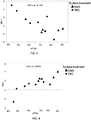
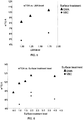
- the hydrophobic polymer improves the dispersion of the pigment, especially when it is used in an electrophoretic medium As a result, electrophoretic media including the pigments have a greater dynamic range between "white” and “colored” states.
- the pigments of the invention also switch between “white” and “colored” states faster than similarly-colored state-of-the-art pigments when both pigments are driven with the same voltage.
- the invention includes colored pigments comprising Formula VI: wherein R 1 is a hydrogen, a C 1 -C 3 alkyl group, a halogen, a hydroxyl, or -COCR 3 CR 4 COOH, R 2 is a hydrogen, C 1 -C 3 alkyl group, or a halogen, R 3 is hydrogen, and R 4 is hydrogen.
- R 1 is a hydrogen, a C 1 -C 3 alkyl group, a halogen, a hydroxyl, or -COCR 3 CR 4 COOH
- R 2 is a hydrogen, C 1 -C 3 alkyl group, or a halogen
- R 3 is hydrogen
- R 4 is hydrogen.
- the pigment is magenta, red, violet, or pink, however multiple species of Formula VI can be combined to tune a bulk pigment to the desired color.
- the pigment of Formula VI is reacted with a hydrophobic polymer, such as a methacrylate or acrylate, such as lauryl acrylate, lauryl methacrylate, 2-ethylhexyl acrylate, 2-ethylhexyl methacrylate, hexyl acrylate, hexyl methacrylate, n-octyl acrylate, n-octyl methacrylate, n-octadecyl acrylate, or n-octadecyl methacrylate.
- a hydrophobic polymer such as a methacrylate or acrylate, such as lauryl acrylate, lauryl methacrylate, 2-ethylhexyl acrylate, 2-ethylhexyl methacrylate, hexyl acrylate, hexyl methacrylate, n-octyl acrylate, n-oct
- the polymer functionalized pigment resulting from this reaction may b of Formula VII: wherein R 1 and R 2 are as defined above with respect to Formula VI, and m and n are independently integers between 10 and 200, or of Formula VIII: wherein R 2 is as defined above with respect to Formula VI, and m and n are independently integers between 10 and 200.
- the hydrophobic polymer improves the dispersion of the pigment, especially when it is used in an electrophoretic medium
- electrophoretic media including the pigments of the invention have a greater dynamic range between “white” and “colored” states.
- the pigments of the invention also switch between “white” and “colored” states faster than similarly-colored state-of-the-art pigments when both pigments are driven with the same voltage.
- the invention additionally includes methods of making functionalized pigments of Formula V: wherein R is a hydrogen, C1-C3 alkyl group, or a halogen.
- R is a hydrogen, C1-C3 alkyl group, or a halogen.
- the method includes providing a pigment comprising a colored species of Formula V and reacting the pigment with glycidyl methacrylate, maleic anhydride, or 4-methacryloxyethyl trimellitic anhydride monomers to create a functionalized pigment.Functionalizing pigments of Formula V with glycidyl methacrylate, maleic anhydride, or 4-methacryloxyethyl trimellitic anhydride monomers can be achieved faster and with greater efficiency than prior art methods of functionalizing pigments of Formula V Once the functionalized pigments have been prepared, the functionalized pigments can be combined with hydrophobic polymers, such as a methacrylate or acrylate, such as lauryl acrylate, lauryl methacrylate, 2-ethylhexyl acrylate, 2-ethylhexyl methacrylate, hexyl acrylate, hexyl methacrylate, n-octyl acrylate, n-octyl meth
- the hydrophobic polymer is lauryl methacrylate.
- the hydrophobic polymer and the functionalized pigment are ball milled prior to reacting.
- the described pigments can be used in an electrophoretic medium, the first and third species of particles move in one direction relative to the electric field and the second species of particles move in the opposed direction relative to the electric field.
- a second addressing impulse larger than the first addressing impulse but of the same polarity is applied to the electrophoretic medium, the first species of particles move in said one direction relative to the electric field, while the second and third species of particles move in said opposed direction relative to the electric field.
- this invention provides an electrophoretic display capable of rendering multiple different colors, the display comprising an electrophoretic medium and first and second electrodes disposed on opposed sides of the electrophoretic medium.
- the electrophoretic medium comprises a fluid and a plurality of a first species of particles having a negative charge, a plurality a second species of particles having a positive charge, and a plurality of a third species of particles having a positive charge.
- this invention provides an electrophoretic medium comprising a fluid and first, second and third species of particles disposed in the fluid.
- the fluid is dyed a first color.
- the first species of particles are light-scattering, and bear charges of one polarity, while the second and third species of particles are non-light scattering, are of second and third colors respectively different from the first color and from each other, and bear charges of the opposite polarity.
- the characteristics of the first, second and third species of particles are such that the particle-particle interactions are less between the particles of the first species and the particles of the second species than between the particles of the first species and the particles of the third species.
- This invention also provides an electrophoretic display capable of rendering multiple different colors, the display comprising an electrophoretic medium and first and second electrodes disposed on opposed sides of the electrophoretic medium.
- the electrophoretic medium comprises a fluid dyed a first color; a plurality of a first species of light-scattering particles having a negative charge; a plurality of a second species of non-light scattering particles having a second color and a positive charge; and a plurality of a third species of non-light-scattering particles having a third color and a positive charge.
- the present invention provides an electrophoretic medium comprising a fluid and at least one type of charged particle disposed in the fluid and capable of moving through the fluid when an electric field is applied to the medium, the medium further comprising a charge-control adjuvant capable of imparting a more positive charge to the charged particles, wherein the charge-control adjuvant is a metal salt of a carboxylic acid, wherein the metal is chosen from the group consisting of lithium, magnesium, calcium, strontium, rubidium, barium, zinc, copper, tin, titanium, manganese, iron, vanadium, and aluminum.
- This invention extends to a front plane laminate, double release sheet, inverted front plane laminate or electrophoretic display comprising an electrophoretic medium of the present invention.
- the displays of the present invention may be used in any application in which prior art electro-optic displays have been used.
- the present displays may be used in electronic book readers, portable computers, tablet computers, cellular telephones, smart cards, signs, watches, shelf labels and flash drives.
- a quinacridone pigment can be surface functionalized with a functional molecule, such as glycidyl methacrylate, maleic anhydride, or 4-methacryloxyethyl trimellitic anhydride to create a functionalized pigment, whereupon the functional groups can be activated to bond hydrophobic polymers, thereby coating the pigment with the hydrophobic polymer.
- a functional molecule such as glycidyl methacrylate, maleic anhydride, or 4-methacryloxyethyl trimellitic anhydride
- the hydrophobic polymers will be methacrylates or acrylates, such as lauryl acrylate, lauryl methacrylate, 2-ethylhexyl acrylate, 2-ethylhexyl methacrylate, hexyl acrylate, hexyl methacrylate, n-octyl acrylate, n-octyl methacrylate, n-octadecyl acrylate, or n-octadecyl methacrylate
- the quinacridone pigment will be functionalized with glycidyl methacrylate, and then polymer coated with lauryl methacrylate, resulting in polymer coated pigments of Formula IV, below: wherein R 2 is a hydrogen, C 1 -C 3 alkyl group, or a halogen, and m and n are independently positive integers between 10 and 200.
- the quinacridone pigment will be functionalized with maleic anhydride, and then polymer coated with lauryl methacrylate, resulting in polymer coated pigments of Formula VIII, below: wherein R 2 is a hydrogen, C 1 -C 3 alkyl group, or a halogen, and m and n are independently positive integers between 10 and 200.
- the pigments will be formed from functionalized pigments of Formula II: wherein R 2 is a hydrogen, C 1 -C 3 alkyl group, or a halogen, R 4 is -OH or-O[CH 2 CH(CH 2 OCOC(CH 3 )CH 2 )O] x H and x is an integer from 1 to 15.
- the pigments may be of Formula IX:
- the functionalized pigments of any of the Formulae above can be coated with hydrophobic polymers, i.e., as described herein.
- quinacridone pigments typically exist as colored crystals prior to being functionalized. Accordingly, the quinacridone molecules that are functionalized using the methods of the invention are often located at the outer surface of the crystal. Accordingly, a varying amount of functionalization may be achieved for individual quinacridone molecules depending upon the location and orientation of the quinacridone molecule with respect to the larger crystal structure. Additionally, during the functionalization and processing, it is likely that some amount of quinacridone will dissociate from the crystal, whereby the dissociated quinacridone may undergo complete functionalization and widespread coupling to the provided hydrophobic polymers. Details of quinacridone crystal structures can be found in the literature, for example Panina et al., Journal of Applied Crystallography (2007) p. 105-114 .
- Displays of the present invention can reproduce the appearance of high quality color printing.
- Such high quality printing is typically effected using at least three colorants in a subtractive primary color system, typically cyan/magenta/yellow (CMY) and optionally black.
- CMY cyan/magenta/yellow
- CMY cyan/magenta/yellow
- a non-shutter-mode electrophoretic medium should be capable of modulating four colors (white and three primary colors, the three primary colors typically being cyan, magenta and yellow, or red, green and blue).
- a black material may also be included, but it is possible to render black by a combination of cyan, magenta and yellow colors.
- a typical electrophoretic medium comprises a fluid, a plurality of electrophoretic particles disposed in the fluid and capable of moving through the fluid (i.e., translating, and not simply rotating) upon application of an electric field to the fluid.
- the fluid also typically contains at least one charge control agent (CCA), a charging adjuvant, and a polymeric rheology modifier.
- the fluid contains the charged electrophoretic particles, which move through the fluid under the influence of an electric field.
- a preferred suspending fluid has a low dielectric constant (about 2), high volume resistivity (about 10 ⁇ 15 >Ohm ⁇ cm), low viscosity (less than 5 mPas), low toxicity and environmental impact, low water solubility (less than 10 parts per million (ppm), if traditional aqueous methods of encapsulation are to be used; note however that this requirement may be relaxed for non-encapsulated or certain microcell displays), a high boiling point (greater than about 90° C.), and a low refractive index (less than 1.5).
- the last requirement arises from the use of scattering (typically white) pigments of high refractive index, whose scattering efficiency depends upon a mismatch in refractive index between the particles and the fluid.
- Organic solvents such as saturated linear or branched hydrocarbons, silicone oils, halogenated organic solvents, and low molecular weight halogen-containing polymers are some useful fluids.
- the fluid may comprise a single component or may be a blend of more than one component in order to tune its chemical and physical properties.
- Reactants or solvents for the microencapsulation process if used, such as oil soluble monomers, can also be contained in the fluid.
- Useful organic fluids include, but are not limited to, saturated or unsaturated hydrocarbons (such as, but are not limited to, dodecane, tetradecane, the aliphatic hydrocarbons in the ISOPAR® series (Exxon, Houston, Texas), NORPAR® (Exxon, a series of normal paraffinic liquids), SHELL-SOL® (Shell, Houston, Texas), and SOL-TROL® (Shell), naphtha, and other petroleum solvents; silicone oils (such as, but are not limited to, octamethyl cyclosiloxane and higher molecular weight cyclic siloxanes, poly(methyl phenyl siloxane), hexamethyldisiloxane, and polydimethylsiloxane; vinyl ethers, such as cyclohexyl vinyl ether and DECAVE® (International Flavors & Fragrances, Inc., New York, NY); aromatic hydrocarbons, such as toluene; and
- the fluid it is advantageous in some electrophoretic media of the present invention for the fluid to contain an optically absorbing dye.
- This dye must be soluble or dispersible in the fluid, but will generally be insoluble in the other components of the microcapsule.
- the dye can be a pure compound, or blends of dyes may be used to achieve a particular color, including black.
- the dyes can be fluorescent, which would produce a display in which the fluorescence properties depend on the position of the particles.
- the dyes can be photoactive, changing to another color or becoming colorless upon irradiation with either visible or ultraviolet light, providing another means for obtaining an optical response. Dyes could also be polymerizable by, for example, thermal, photochemical or chemical diffusion processes, forming a solid absorbing polymer inside the bounding shell.
- dyes can be used in electrophoretic media. Important dye properties include light fastness, solubility or dispersibility in the fluid, color, and cost.
- the dyes are generally chosen from the classes of azo, azomethine, fluoran, anthraquinone, and triphenylmethane dyes and may be chemically modified so as to increase their solubility in the fluid and reduce their adsorption to the particle surfaces.
- the electrophoretic particles used in the media and displays of the present invention are preferably white, black, yellow, magenta, cyan, red, green, or blue in color, although other (spot) colors may also be used. There is much flexibility in the choice of such particles.
- an electrophoretic particle is any particle that is insoluble in the fluid and charged or capable of acquiring a charge (i.e., has or is capable of acquiring electrophoretic mobility). In some cases, this mobility may be zero or close to zero (i.e., the particles will not move).
- the particles may be, for example, non-derivatized pigments or dyed (laked) pigments, or any other component that is charged or capable of acquiring a charge.
- the particles may be organic or inorganic compounds, and they may either absorb light or scatter light, i.e., the particles for use in the invention may include scattering pigments, absorbing pigments and luminescent particles.
- the particles may be retroreflective or they may be electroluminescent, such as zinc sulfide particles, or they may be photoluminescent.
- the electrophoretic particle may have any shape, i.e., spherical, plate-like or acicular.
- a scattering particle typically has high refractive index, high scattering coefficient, and low absorption coefficient and may be composed of an inorganic material such as rutile (titania), anatase (titania), barium sulfate, zirconium oxide, kaolin, or zinc oxide.
- Other particles are absorptive, such as carbon black or colored organic or inorganic pigments such as are used in paints and inks.
- a reflective material can also be employed, such as a metallic particle.
- Useful particle diameters may range from 10 nm up to about 10 ⁇ m, although for light-scattering particles it is preferred that the particle diameter not be smaller than about 200 nm.
- Particularly preferred raw pigment particles of the present invention are red pigments such as Pigment Red 112, Pigment Red 179, Pigment Red 188 and Pigment Red 254 and magenta pigments such as Pigment Violet 19, Pigment Red 52:2 and Pigment Red 122.
- These pigments are based upon the quinacridone molecule, a version of which is shown below in Formula V: wherein R is a hydrogen, C 1 -C 3 alkyl group, or a halogen.
- Other quinacridones, having structures not covered by Formula V may also be polymer coated using the techniques described herein.
- a pre-milled combination of Pigment Violet 19 (CAS# 1047-16-1) and Pigment Red 122 (CAS# 980-26-7) is commercially available from Clariant (Basel, Switzerland) as Ink Jet Magenta E 02 VP2621.
- Raw pigments for use in the electrophoretic particles include, but are not limited to, PbCrO 4 , Cyan blue GT 55-3295 (American Cyanamid Company, Wayne, NJ), Cibacron Black BG (Ciba Company, Inc., Newport, Delaware), Cibacron Turquoise Blue G (Ciba), Cibalon Black BGL (Ciba), Orasol Black BRG (Ciba), Orasol Black RBL (Ciba), Acetamine Black, CBS (E. I.
- CF (GAF) (15710), Diamond Black PBBA Ex (GAF) (16505); Direct Deep Black EA Ex CF (GAF) (30235), Hansa Yellow G (GAF) (11680); Indanthrene Black BBK Powd. (GAF) (59850), Indocarbon CLGS Conc. CF (GAF) (53295), Katigen Deep Black NND Hi Conc. CF (GAF) (15711), Rapidogen Black 3 G (GAF) (Azoic Black 4); Sulphone Cyanine Black BA-CF (GAF) (26370), Zambezi Black VD Ex Conc.
- the electrophoretic particles may also include laked, or dyed, pigments.
- Laked pigments are particles that have a dye precipitated on them or which are stained.
- Lakes are metal salts of readily soluble anionic dyes. These are dyes of azo, triphenylmethane or anthraquinone structure containing one or more sulphonic or carboxylic acid groupings. They are usually precipitated by a calcium, barium or aluminum salt onto a substrate. Typical examples are peacock blue lake (Cl Pigment Blue 24) and Persian orange (lake of Cl Acid Orange 7), Black M Toner (GAF) (a mixture of carbon black and black dye precipitated on a lake).
- peacock blue lake Cl Pigment Blue 24
- Persian orange lake of Cl Acid Orange 7
- GAF Black M Toner
- pigments in the three subtractive primary colors have high extinction coefficients and sufficiently small particle size as to be substantially non scattering of incident light.
- Composite particle i.e., polymeric particles that incorporate smaller pigment particles or dyes
- Pigments may be surface-functionalized as described below or may be used without functionalization.
- the electrophoretic media of the present invention will typically contain a charge control agent (CCA), and may contain a charge director.
- CCA charge control agent
- These electrophoretic media components typically comprise low molecular weight surfactants, polymeric agents, or blends of one or more components and serve to stabilize or otherwise modify the sign and/or magnitude of the charge on the electrophoretic particles.
- the CCA is typically a molecule comprising ionic or other polar groupings, hereinafter referred to as head groups. At least one of the positive or negative ionic head groups is preferably attached to a non-polar chain (typically a hydrocarbon chain) that is hereinafter referred to as a tail group. It is thought that the CCA forms reverse micelles in the internal phase and that it is a small population of charged reverse micelles that leads to electrical conductivity in the very non-polar fluids typically used as electrophoretic fluids.
- Reverse micelles comprise a highly polar core (that typically contains water) that may vary in size from 1 nm to tens of nanometers (and may have spherical, cylindrical, or other geometry) surrounded by the non-polar tail groups of the CCA molecule.
- Reverse micelles have been extensively studied, especially in ternary mixtures such as oil/water/surfactant mixtures.
- An example is the iso-octane/water/AOT mixture described, for example, in Payer et al., J. Chem, Phys., 131, 14704 (2009 ).
- phase In electrophoretic media, three phases may typically be distinguished: a solid particle having a surface, a highly polar phase that is distributed in the form of extremely small droplets (reverse micelles), and a continuous phase that comprises the fluid. Both the charged particles and the charged reverse micelles may move through the fluid upon application of an electric field, and thus there are two parallel pathways for electrical conduction through the fluid (which typically has a vanishingly small electrical conductivity itself).
- the polar core of the CCA is thought to affect the charge on surfaces by adsorption onto the surfaces.
- adsorption may be onto the surfaces of the electrophoretic particles or the interior walls of a microcapsule (or other solid phase, such as the walls of a microcell) to form structures similar to reverse micelles, these structures hereinafter being referred to as hemi-micelles.
- hemi-micelles When one ion of an ion pair is attached more strongly to the surface than the other (for example, by covalent bonding), ion exchange between hemi-micelles and unbound reverse micelles can lead to charge separation in which the more strongly bound ion remains associated with the particle and the less strongly bound ion becomes incorporated into the core of a free reverse micelle.
- the ionic materials forming the head group of the CCA may induce ion-pair formation at the particle (or other) surface.
- the CCA may perform two basic functions: charge-generation at the surface and charge-separation from the surface.
- the charge-generation may result from an acid-base or an ion-exchange reaction between some moiety present in the CCA molecule or otherwise incorporated into the reverse micelle core or fluid, and the particle surface.
- useful CCA materials are those which are capable of participating in such a reaction, or any other charging reaction as known in the art.
- Non-limiting classes of charge control agents which are useful in the media of the present invention include organic sulfates or sulfonates, metal soaps, block or comb copolymers, organic amides, organic zwitterions, and organic phosphates and phosphonates.
- Useful organic sulfates and sulfonates include, but are not limited to, sodium bis(2-ethylhexyl) sulfosuccinate, calcium dodecylbenzenesulfonate, calcium petroleum sulfonate, neutral or basic barium dinonylnaphthalene sulfonate, neutral or basic calcium dinonylnaphthalene sulfonate, dodecylbenzenesulfonic acid sodium salt, and ammonium lauryl sulfate.
- Useful metal soaps include, but are not limited to, basic or neutral barium petronate, calcium petronate, cobalt, calcium, copper, manganese, magnesium, nickel, zinc, aluminum and iron salts of carboxylic acids such as naphthenic, octanoic, oleic, palmitic, stearic, and myristic acids and the like.
- Useful block or comb copolymers include, but are not limited to, AB diblock copolymers of (A) polymers of 2-(N,N-dimethylamino)ethyl methacrylate quaternized with methyl p-toluenesulfonate and (B) poly(2-ethylhexyl methacrylate), and comb graft copolymers with oil soluble tails of poly(12-hydroxystearic acid) and having a molecular weight of about 1800, pendant on an oil-soluble anchor group of poly(methyl methacrylate-methacrylic acid).
- Useful organic amides/amines include, but are not limited to, polyisobutylene succinimides such as OLOA 371 or 1200 (available from Chevron Oronite Company LLC, Houston, Tex.), or SOLSPERSE® 17000 (available from Lubrizol, Wickliffe, OH), and N-vinylpyrrolidone polymers.
- Useful organic zwitterions include, but are not limited to, lecithin.
- Useful organic phosphates and phosphonates include, but are not limited to, the sodium salts of phosphated mono- and di-glycerides with saturated and unsaturated acid substituents.
- Useful tail groups for CCA include polymers of olefins such as poly(isobutylene) of molecular weight in the range of 200 - 10,000.
- the head groups may be sulfonic, phosphoric or carboxylic acids or amides, or alternatively amino groups such as primary, secondary, tertiary or quaternary ammonium groups.
- Charge adjuvants used in the media of the present invention may bias the charge on electrophoretic particle surfaces, as described in more detail below.
- Such charge adjuvants may be Bronsted or Lewis acids or bases.
- Particle dispersion stabilizers may be added to prevent particle flocculation or attachment to the capsule or other walls or surfaces.
- non-aqueous surfactants include, but are not limited to, glycol ethers, acetylenic glycols, alkanolamides, sorbitol derivatives, alkyl amines, quaternary amines, imidazolines, dialkyl oxides, and sulfosuccinates.
- the bistability of electrophoretic media can be improved by including in the fluid a polymer having a number average molecular weight in excess of about 20,000, this polymer being essentially non-absorbing on the electrophoretic particles; poly(isobutylene) is a preferred polymer for this purpose.
- a particle with immobilized charge on its surface sets up an electrical double layer of opposite charge in a surrounding fluid.
- Ionic head groups of the CCA may be ion-paired with charged groups on the electrophoretic particle surface, forming a layer of immobilized or partially immobilized charged species.
- a diffuse layer comprising charged (reverse) micelles comprising CCA molecules in the fluid.
- an applied electric field exerts a force on the fixed surface charges and an opposite force on the mobile counter-charges, such that slippage occurs within the diffuse layer and the particle moves relative to the fluid.
- the electric potential at the slip plane is known as the zeta potential.
- FIG 1 of the accompanying drawings is a schematic cross-section through an electrophoretic display (generally designated 100) of the present invention comprising an encapsulated electrophoretic medium; such a display, and methods for its manufacture are described in U.S. Patent No. 6,982,178 .
- the display 100 comprises a light-transmissive substrate 102, typically a transparent plastic film, such as a sheet of poly(ethylene terephthalate) (PET) about 25 to 200 ⁇ m in thickness.
- PET poly(ethylene terephthalate)
- the substrate 102 may comprise one or more additional layers, for example a protective layer to absorb ultra-violet radiation, barrier layers to prevent ingress of oxygen or moisture into the display, and anti-reflection coatings to improve the optical properties of the display.
- additional layers for example a protective layer to absorb ultra-violet radiation, barrier layers to prevent ingress of oxygen or moisture into the display, and anti-reflection coatings to improve the optical properties of the display.
- the substrate 102 carries a thin, light-transmissive, electrically-conductive layer 104 that acts as the front electrode of the display.
- Layer 104 may comprise a continuous coating of electrically-conductive material with minimal intrinsic absorption of electromagnetic radiation in the visible spectral range such as indium tin oxide (ITO), poly(3,4-ethylenedioxythiophene) poly(styrenesulfonate) (PEDOT:PSS), graphene and the like, or may be a discontinuous layer of a material such as silver (in the form of, for example, nanowires or printed grids) or carbon (for example in nanotube form) that absorb or reflect visible light but are present at such a surface coverage that the layer as a whole is effectively transparent.
- ITO indium tin oxide
- PEDOT:PSS poly(3,4-ethylenedioxythiophene) poly(styrenesulfonate)
- graphene graphene and the like
- a discontinuous layer of a material such as silver (
- a layer (generically designated 108) of an electrophoretic medium is in electrical contact with the conductive layer 104 through an optional polymeric layer or layers 106, as described in more detail below.
- the electrophoretic medium 108 is shown as an encapsulated electrophoretic medium comprising a plurality of microcapsules. The microcapsules may be retained within a polymeric binder. Upon application of an electrical field across the layer 108, negatively-charged particles therein move towards the positive electrode and positively-charged particles move towards the negative electrode, so that the layer 108 appears, to an observer viewing the display through the substrate 102, to change color.
- Layer 108 may be encapsulated or comprise sealed or unsealed micro-cells or micro-cups, or may be non-encapsulated.
- the electrophoretic internal phase (the electrophoretic particles and fluid) may be located between two planar electrodes, at least one of which is light-transmissive.
- the spacing between the electrodes may be controlled by the use of spacers, which may have the form of ribs or beads. Alternatively, the spacing may be controlled by the use of microcapsules containing the internal phase; the internal phase may be located within and outside the capsules.
- the internal phase inside and outside the microcapsules be identical, although in certain circumstances this may be preferred.
- capsules containing the same internal phase as that outside the capsules are used as spacers it may be that the presence of the spacers is less easily discernible by a viewer of the display (since the internal and external internal phases would switch to at least substantially the same color).
- the display 100 further comprises a layer 110 of lamination adhesive covering the electrophoretic layer 108.
- the lamination adhesive makes possible the construction of an electro-optic display by combining two subassemblies, namely a backplane 118 that comprises an array of pixel electrodes 112 and an appropriate arrangement of conductors to connect the pixel electrodes to drive circuitry, and a front plane 116 that comprises the substrate 102 bearing the transparent electrode 104, the electrophoretic layer 108, the lamination adhesive 110 and optional additional components such as polymeric layer or layers 106.
- the front plane 116 is laminated to the backplane 118 by means of lamination adhesive 110.
- the lamination adhesive may be cured thermally or by actinic radiation (for example, by UV curing) or may be uncured.
- the lamination adhesive 110 is in the electrical path from the backplane electrodes 112 to the front electrode 104, its electrical properties must be carefully tailored.
- the lamination adhesive may comprise, in addition to a polymeric material, an ionic dopant that may be an additive selected from a salt, a polyelectrolyte, a polymer electrolyte, a solid electrolyte, a conductive metal powder, a ferrofluid, a non-reactive solvent, a conductive organic compound, and combinations thereof.
- the volume resistivities of encapsulated electrophoretic media of the present invention are typically around 10 10 Ohm ⁇ cm, and the resistivities of other electro-optic media are usually of the same order of magnitude. Accordingly, the volume resistivity of the lamination adhesive is normally around 10 8 to 10 12 Ohm ⁇ cm at the operating temperature of the display, which is typically around 20°C.
- Polymeric layer 106 may be a lamination adhesive layer with similar properties to those of lamination adhesive layer 110 (see for example U.S. Patent No. 7,839,564 ), except that, since polymeric layer 106 is adjacent to the non-pixelated, light-transmissive common electrode 104, its electrical conductivity may be higher than that of lamination adhesive layer 110, which is adjacent to the pixelated back plane electrodes 112 and cannot be so conductive as to lead to significant currents flowing from one backplane electrode to its neighbors when they are held at different potentials during switching of the display.
- polymeric layer 106 is a lamination adhesive it may be used to affix electrophoretic layer 108 to front electrode 104 during manufacture of the front plane as described in detail in the aforementioned United States Patent No. 6,982,178 .
- the present invention provides an electrophoretic medium comprising a fluid and at least a first species of particles disposed in the fluid, the first species of particles being such that when a first electric field is applied to the medium for a first period, thereby applying a first addressing impulse to the medium, the first species of particles move in one direction relative to the electric field, but when a second electric field, having the same polarity as the first electric field, is applied to the medium for a second period, thereby applying a second addressing impulse larger than the first addressing impulse to the medium, the first species of particles move in the opposed direction relative to the electric field.
- the following hypothesis as to how the pigment particles might move in a first direction with a first addressing impulse (i.e., behaving as though the particles bore a negative charge) and in a second direction with a second, higher addressing impulse (i.e., behaving as though the particles bore a positive charge) is provided, but the invention is in no way limited by this hypothesis.
- the waveforms used to drive displays of the present invention may modulate the electrical impulse provided to the display using any one or more of at least four different methods:
- impulse is used to denote the integral of the applied voltage with respect to time during the period in which a medium or display is addressed.
- a certain electrochemical or displacement current is required for the change in direction of a (typically negatively-charged) species of particle or the disaggregation of Coulombic aggregates, and thus when a high impulse is to applied to a medium of display, the addressing voltage must be sufficient to provide such a current.
- Lower impulses may be provided by lower addressing voltages, or by reduction in the addressing time at the same higher voltage.
- FIGS. 2A and 2B are schematic cross-sections showing various possible states of single microcapsule 800 (a sealed or unsealed microcell, or other similar enclosure may alternatively be used), containing a fluid 806 dyed with a yellow dye (uncharged yellow particles may be substituted for the yellow dye. Disposed in the fluid 806 are positively-charged light-transmissive magenta particles 802 and negatively-charged white particles 804.
- a substantially transparent front electrode 810 the upper surface of which (as illustrated) forms the viewing surface of the display, while on the opposed side of the microcapsule 800 is a rear or pixel electrode 812.
- the front electrode 810 remains at ground potential (although this is not an essential feature of the present invention, and variation of the potential of this electrode may be desirable in some instances, for example to provide higher electric fields), and that the electric field across microcapsule 800 is controlled by changing the voltage of the rear electrode 812.
- FIGS 2A and 2B illustrate separation of charged color particles (802 and 804) within the microcapsule 800 when a voltage is applied across an electrophoretic medium, thereby causing particles 802 and 804 to undergo electrophoretic motion.
- FIG. 2A when the rear electrode 812 is at a positive voltage, the white particles 804 move towards the rear electrode 812, while the magenta particles 802 lie adjacent the front electrode 810.
- the microcapsule 800 displays a red color caused by the combination of the magenta particles and the yellow dye viewed against the white background provided by the white particles. (View is assumed to be above, but in the approximate plane of the figure in FIGS. 2A and 2B .) As shown in FIG.
- the white particles 804 move adjacent the front electrode 810, and the microcapsule 800 displays a white color (both the yellow fluid 806 and the magenta particles 802 are masked by the white particles 804).
- the white and magenta particles, and yellow dye used in FIGS. 2A and 2B .
- Especially preferred embodiments of the present invention are those in which one dye or particle has one of the additive primary colors, and another is of the complementary subtractive primary color.
- the dye might be cyan and the two particles white and red.
- Other combinations of particles, including multiple particle groups having the same charge polarity, but different charge magnitudes, are also possible.
- green/magenta and blue/yellow combinations of dye and particle may be used, together with a white particle.
- the fluid 806 may optionally be colorless.
- the first (white) particle is a silanol-functionalized scattering material such as titanium dioxide to which a polymeric material has been attached;
- the second particle is a positively charged magenta material such as quinacridone pigment that has been coated as described below.
- An electrophoretic display may additionally include a dye.
- the dye in some embodiments is a hydrocarbon (ISOPAR® E)-soluble material that may be an azo dye such as Sudan I or Sudan II or derivatives thereof.
- Other hydrocarbon-soluble dyes such as azomethine (yellow and cyan are readily available) or other materials that are well-known in the art may also be.
- This Example illustrates the preparation of a magenta polymer coated pigment and the incorporation of the pigment into a test display of the type illustrated in the accompanying drawings.
- Ink Jet Magenta E 02 VP2621 available from Clariant, Basel, Switzerland, was dispersed in toluene.
- the resultant dispersion was transferred to a 500 mL round-bottomed flask and the flask degassed with nitrogen.
- the reaction mixture was then brought to 45°C, and, upon temperature equilibration, glycidyl methacrylate (GMA) monomer was added and the reaction was allowed to stir at 45°C for four hours.
- the resulting reaction mixture was allowed to cool to room temperature and then poured into a 1 L plastic centrifuge bottle, diluted with toluene and centrifuged at 3500 RPM for 20 minutes.
- the centrifuge cake was washed twice with toluene, each time the mixture was centrifuged at 3500 RPM for 20 minutes. After the final wash, the supernatant was decanted and the resultant pigment was dried in a 70°C vacuum oven overnight, then ground with a mortar and pestle. This procedure produces magenta pigment functionalized with an acrylate group to which a polymeric chain could be attached.
- the dried functionalized pigment was then dispersed in toluene and lauryl methacrylate (LMA) monomer with ball milling with Zirconox grinding media and a roll mill, and the resultant dispersion transferred to a jacketed 500 mL rector equipped with an overhead stirrer and brought to 65°C via a circulating water bath.
- the system was purged with nitrogen for at least one hour, and then a solution of AIBN (2,2'-azobis(2-methylpropionitrile)) in toluene was metered into the reaction.
- the reaction mixture was stirred vigorously at 65°C for 16 hours, then poured into a 1 L plastic centrifuge bottle, diluted with toluene and centrifuged at 4500 RPM for 30 minutes.
- the centrifuge cake was washed once with toluene and the mixture was again centrifuged at 4500 RPM for 30 minutes. The supernatant was decanted and the resultant pigment was dried in a 70°C vacuum oven overnight. This procedure produces a magenta pigment with a covalently bound polymeric shell with a typical molecular weight of 35 - 120 kDA. See Formula II.
- the polymerized pigment was then ground with a mortar and pestle, and dispersed in ISOPAR® E to form a 20 weight % dispersion, which was sonicated and rolled on a roll mill for 24 hours. The resultant dispersion was filtered through fabric mesh to remove any large particles, a sample removed and its solids content measured.
- the magenta pigment dispersion prepared in Part A above (13.92 g of a 14% w/w dispersion in ISOPAR® E) was combined with 83.07 g of a 60% w/w ISOPAR® E dispersion of titanium dioxide (polymer coated as described in the aforementioned U.S. Patent No. 7,002,728 ), 7.76 g of a 20% w/w solution of SOLSPERSE® 17000 in ISOPAR® E, a 15% w/w solution of poly(isobutylene) of molecular weight 1270 kDa in ISOPAR® E (this poly(isobutylene) acts as an image stabilizer; see U.S. Patent No. 7,170,670 ), and 5.82 g of ISOPAR® E.
- the resultant mixture was dispersed overnight on a mechanical roller to produce an internal phase ready for encapsulation and having a conductivity of 304.7 pS/cm.
- the internal phase prepared in Part B was encapsulated following the procedure described in U.S. Patent No. 7,002,728 .
- the resultant encapsulated material was isolated by sedimentation, washed with deionized water, and size-separated by sieving.
- Capsule size analysis using a Coulter Multisizer showed that the resulting capsules had a mean size of 40 ⁇ m and more than 85 percent of the total capsule volume was in capsules having the desired size of between 20 and 60 ⁇ m.
- the sieved capsules produced in Part C above were adjusted to pH 9 with ammonium hydroxide solution and excess water removed. The capsules were then concentrated and the supernatant liquid discarded. The concentrated capsules were mixed with an aqueous polyurethane binder (prepared in a manner similar to that described in U. S. Patent Application Publication No. 2005/0124751 ) at a ratio of 1 part by weight binder to 15 parts by weight of capsules following which Triton X-100 surfactant and hydroxypropylmethylcellulose were added and mixed thoroughly to provide a slurry.
- an aqueous polyurethane binder prepared in a manner similar to that described in U. S. Patent Application Publication No. 2005/0124751 ) at a ratio of 1 part by weight binder to 15 parts by weight of capsules following which Triton X-100 surfactant and hydroxypropylmethylcellulose were added and mixed thoroughly to provide a slurry.
- the capsule slurry thus prepared was coated onto the indium tin oxide (ITO) coated surface of a poly(ethylene terephthalate) (PET)/ITO film of 125 ⁇ m thickness using a bar coater, and the coated film dried at 60°C.
- a layer of polyurethane adhesive doped with tetraethylammonium hexafluorophosphate as a conductive dopant was coated onto a release sheet, and the resultant PET film/adhesive sub-assembly was laminated on top of the coated capsules as described in the above-mentioned U.S. Patent No. 7,002,728 .
- the release sheet was removed and the resultant multilayer structure was laminated onto a graphite rear electrode to produce an experimental single-pixel display comprising, in order from its viewing surface, the PET film, a layer of ITO, a capsule layer, a lamination adhesive layer, and the graphite rear electrode.
- the resulting displays were switched using a square-wave AC waveform applied to the graphite rear electrode (while the front ITO electrode was grounded) of ⁇ 30V and 50 Hz that was offset from zero as specified below.
- the DC offset for red/white switching was ⁇ 10V.
- the white and magenta pigments move though the non-polar fluid.
- the red state results from viewing of the magenta (green-absorbing) pigment against the white background.
- the DC offset for magenta/white switching was ⁇ 60V.
- the white color was obtained as the white pigment moved away from the viewing side of the display towards the negatively-charged rear electrode, as described above with reference to FIGS. 2A and 2B .
- Magenta pigments functionalized with glycidyl methacrylate (GMA) and coated with lauryl methacrylate were compared to state-of-the art magenta pigments.
- the state-of-the-art pigments were produced as described in U.S. Patent Application No. 2014/0340430 , which is incorporated by reference in its entirety.
- the state-of-the-art magenta pigments were produced in a manner similar to that described above in Part A, however the magenta pigment was functionalized with 4-vinylbenzylchloride (VBA) prior to coating with lauryl methacrylate (LMA).
- VBA 4-vinylbenzylchloride
- LMA lauryl methacrylate
- the amount of functionalized monomer and the amount of surface coating polymer were also varied to evaluate how these features altered the overall performance of the pigment in an electrophoretic display.
- FIGS. 3 and 4 refer to "washed" TGA because the pigments were washed in tetrahydrofuran to assure that any loose polymer was removed from the pigment.) As shown in FIGS. 3 and 4 , the overall performance of a colored/white pigment system in an electrophoretic display roughly tracks TGA.
- white state contamination (WS c) and color saturation (CS c) do vary somewhat for magenta pigments with the same polymer coating weight but different functional elements (GMA vs. VBC). Compare, for example, the points for GMA and VBC with a wTGA of about 7%, where the white state contamination of the GMA pigment particles is clearly better.
- Ink Jet Magenta E 02 VP2621 available from Clariant, Basel, Switzerland, was dispersed in toluene.
- the resultant dispersion was transferred to a 500 mL round-bottomed flask and the flask degassed with nitrogen.
- the reaction mixture was then brought to 45°C, and, upon temperature equilibration, maleic anhydride was added and the reaction was allowed to stir at 65°C for sixteen hours.
- the resulting reaction mixture was allowed to cool to room temperature and then poured into a 1 L plastic centrifuge bottle, diluted with toluene and centrifuged at 3500 RPM for 20 minutes.
- the centrifuge cake was washed twice with toluene, each time the mixture was centrifuged at 3500 RPM for 20 minutes. After the final wash, the supernatant was decanted and the resultant pigment was dried in a 70°C vacuum oven overnight, then ground with a mortar and pestle. This procedure produces magenta pigment functionalized with an acrylate group to which a polymeric chain could be attached. See Formula IV.
- the dried functionalized pigment thus was dispersed in toluene and lauryl methacrylate (LMA) monomer with ball milling with Zirconox grinding media and a roll mill, and the resultant dispersion transferred to a jacketed 500 mL rector equipped with an overhead stirrer and brought to 65°C via a circulating water bath.
- the system was purged with nitrogen for at least one hour, and then a solution of AIBN (2,2'-azobis(2-methylpropionitrile)) in toluene was metered into the reaction.
- the reaction mixture was stirred vigorously at 65°C for 16 hours, then poured into a 1 L plastic centrifuge bottle, diluted with toluene and centrifuged at 4500 RPM for 30 minutes.
- the centrifuge cake was washed once with toluene and the mixture was again centrifuged at 4500 RPM for 30 minutes. The supernatant was decanted and the resultant pigment was dried in a 70°C vacuum oven overnight. This procedure produces a magenta pigment with a covalently bound polymeric shell with a typical molecular weight of 35 - 120 kDA. See Formula V.
- the polymerized pigment was then ground with a mortar and pestle, and dispersed in ISOPAR® E to form a 20 weight % dispersion, which was sonicated and rolled on a roll mill for 24 hours. The resultant dispersion was filtered through fabric mesh to remove any large particles, a sample removed and its solids content measured.
- Ink Jet Magenta E 02 VP2621 available from Clariant, Basel, Switzerland, will be dispersed in toluene.
- the resultant dispersion will be transferred to a 500 mL round-bottomed flask and the flask degassed with nitrogen.
- the reaction mixture will then be brought to 45°C, and, upon temperature equilibration, 4-methacryloxyethyl trimellitic anhydride will be added and the reaction was allowed to stir at 65°C for sixteen hours.
- the resulting reaction mixture will be allowed to cool to room temperature and then poured into a 1 L plastic centrifuge bottle, diluted with toluene and centrifuged at 3500 RPM for 20 minutes.
- the centrifuge cake will be washed twice with toluene, each time the mixture will be centrifuged at 3500 RPM for 20 minutes. After the final wash, the supernatant will be decanted and the resultant pigment will be dried in a 70°C vacuum oven overnight, then ground with a mortar and pestle. This procedure will produce magenta pigment functionalized with an acrylate group to which a polymeric chain could be attached.
- the dried functionalized pigment will be dispersed in toluene and lauryl methacrylate (LMA) monomer with ball milling with Zirconox grinding media and a roll mill, and the resultant dispersion will be transferred to a jacketed 500 mL rector equipped with an overhead stirrer and brought to 65°C via a circulating water bath.
- the system will be purged with nitrogen for at least one hour, and then a solution of AIBN (2,2'-azobis(2-methylpropionitrile)) in toluene will be metered into the reaction.
- reaction mixture will be stirred vigorously at 65°C for 16 hours, then poured into a 1 L plastic centrifuge bottle, diluted with toluene and centrifuged at 4500 RPM for 30 minutes.
- the centrifuge cake will be washed once with toluene and the mixture will be again centrifuged at 4500 RPM for 30 minutes.
- the supernatant will be decanted and the resultant pigment will be dried in a 70°C vacuum oven overnight. This procedure will produce a magenta pigment with a covalently bound polymeric shell with a typical molecular weight of 35 - 120 kDA.
- the polymerized pigment will be ground with a mortar and pestle, and dispersed in ISOPAR® E to form a 20 weight % dispersion, which will be sonicated and rolled on a roll mill for 24 hours.
- the resultant dispersion will be filtered through fabric mesh to remove any large particles, a sample will be removed and its solids content will be measured.
Landscapes
- Chemical & Material Sciences (AREA)
- Organic Chemistry (AREA)
- Life Sciences & Earth Sciences (AREA)
- Engineering & Computer Science (AREA)
- Wood Science & Technology (AREA)
- Materials Engineering (AREA)
- Chemical Kinetics & Catalysis (AREA)
- Health & Medical Sciences (AREA)
- Medicinal Chemistry (AREA)
- Polymers & Plastics (AREA)
- General Chemical & Material Sciences (AREA)
- Physics & Mathematics (AREA)
- Molecular Biology (AREA)
- Nonlinear Science (AREA)
- Optics & Photonics (AREA)
- General Physics & Mathematics (AREA)
- Electrochemistry (AREA)
- Electrochromic Elements, Electrophoresis, Or Variable Reflection Or Absorption Elements (AREA)
Priority Applications (1)
| Application Number | Priority Date | Filing Date | Title |
|---|---|---|---|
| PL16864970T PL3374435T3 (pl) | 2015-11-11 | 2016-11-10 | Funkcjonalizowane pigmenty chinakrydonowe |
Applications Claiming Priority (2)
| Application Number | Priority Date | Filing Date | Title |
|---|---|---|---|
| US201562253755P | 2015-11-11 | 2015-11-11 | |
| PCT/US2016/061250 WO2017083472A1 (en) | 2015-11-11 | 2016-11-10 | Functionalized quinacridone pigments |
Publications (3)
| Publication Number | Publication Date |
|---|---|
| EP3374435A1 EP3374435A1 (en) | 2018-09-19 |
| EP3374435A4 EP3374435A4 (en) | 2018-11-07 |
| EP3374435B1 true EP3374435B1 (en) | 2020-12-16 |
Family
ID=58667897
Family Applications (1)
| Application Number | Title | Priority Date | Filing Date |
|---|---|---|---|
| EP16864970.5A Active EP3374435B1 (en) | 2015-11-11 | 2016-11-10 | Functionalized quinacridone pigments |
Country Status (9)
| Country | Link |
|---|---|
| US (4) | US9752034B2 (es) |
| EP (1) | EP3374435B1 (es) |
| JP (2) | JP6660465B2 (es) |
| KR (1) | KR101900227B1 (es) |
| CN (2) | CN108350279B (es) |
| ES (1) | ES2848473T3 (es) |
| PL (1) | PL3374435T3 (es) |
| PT (1) | PT3374435T (es) |
| WO (1) | WO2017083472A1 (es) |
Families Citing this family (6)
| Publication number | Priority date | Publication date | Assignee | Title |
|---|---|---|---|---|
| PL3374435T3 (pl) * | 2015-11-11 | 2021-08-02 | E Ink Corporation | Funkcjonalizowane pigmenty chinakrydonowe |
| US11248122B2 (en) * | 2017-12-30 | 2022-02-15 | E Ink Corporation | Pigments for electrophoretic displays |
| WO2020206345A1 (en) * | 2019-04-04 | 2020-10-08 | The Texas A & M University System | Enhancement of polymer mechanical properties using quinacridone additives |
| KR20220031714A (ko) * | 2019-08-26 | 2022-03-11 | 이 잉크 코포레이션 | 식별 마커를 포함하는 전기 광학 디바이스 |
| WO2021062075A1 (en) * | 2019-09-27 | 2021-04-01 | E Ink Corporation | Light-transmissive conductor with directional conductivity |
| US11620959B2 (en) * | 2020-11-02 | 2023-04-04 | E Ink Corporation | Enhanced push-pull (EPP) waveforms for achieving primary color sets in multi-color electrophoretic displays |
Family Cites Families (135)
| Publication number | Priority date | Publication date | Assignee | Title |
|---|---|---|---|---|
| US4418346A (en) | 1981-05-20 | 1983-11-29 | Batchelder J Samuel | Method and apparatus for providing a dielectrophoretic display of visual information |
| JPH0379672A (ja) | 1989-08-23 | 1991-04-04 | Fuji Photo Film Co Ltd | アゾメチン又はインドアニリン系色素の製造方法 |
| GB9418495D0 (en) | 1994-09-14 | 1994-11-02 | Ciba Geigy Ag | Mono-n-alkyl-quinacridone pigments |
| US5745094A (en) | 1994-12-28 | 1998-04-28 | International Business Machines Corporation | Electrophoretic display |
| US8139050B2 (en) | 1995-07-20 | 2012-03-20 | E Ink Corporation | Addressing schemes for electronic displays |
| US7583251B2 (en) | 1995-07-20 | 2009-09-01 | E Ink Corporation | Dielectrophoretic displays |
| US8089453B2 (en) | 1995-07-20 | 2012-01-03 | E Ink Corporation | Stylus-based addressing structures for displays |
| US7327511B2 (en) | 2004-03-23 | 2008-02-05 | E Ink Corporation | Light modulators |
| US7999787B2 (en) | 1995-07-20 | 2011-08-16 | E Ink Corporation | Methods for driving electrophoretic displays using dielectrophoretic forces |
| US7193625B2 (en) | 1999-04-30 | 2007-03-20 | E Ink Corporation | Methods for driving electro-optic displays, and apparatus for use therein |
| US7167155B1 (en) | 1995-07-20 | 2007-01-23 | E Ink Corporation | Color electrophoretic displays |
| US7259744B2 (en) | 1995-07-20 | 2007-08-21 | E Ink Corporation | Dielectrophoretic displays |
| US7411719B2 (en) | 1995-07-20 | 2008-08-12 | E Ink Corporation | Electrophoretic medium and process for the production thereof |
| US6664944B1 (en) | 1995-07-20 | 2003-12-16 | E-Ink Corporation | Rear electrode structures for electrophoretic displays |
| US7956841B2 (en) | 1995-07-20 | 2011-06-07 | E Ink Corporation | Stylus-based addressing structures for displays |
| US6866760B2 (en) | 1998-08-27 | 2005-03-15 | E Ink Corporation | Electrophoretic medium and process for the production thereof |
| US6017584A (en) | 1995-07-20 | 2000-01-25 | E Ink Corporation | Multi-color electrophoretic displays and materials for making the same |
| US5930026A (en) | 1996-10-25 | 1999-07-27 | Massachusetts Institute Of Technology | Nonemissive displays and piezoelectric power supplies therefor |
| US8040594B2 (en) | 1997-08-28 | 2011-10-18 | E Ink Corporation | Multi-color electrophoretic displays |
| US8213076B2 (en) | 1997-08-28 | 2012-07-03 | E Ink Corporation | Multi-color electrophoretic displays and materials for making the same |
| US7002728B2 (en) | 1997-08-28 | 2006-02-21 | E Ink Corporation | Electrophoretic particles, and processes for the production thereof |
| US6001980A (en) * | 1997-09-03 | 1999-12-14 | Hoechst Celanese Corporation | Polyester toner composition for electrophotographic imaging systems |
| JP2002507765A (ja) | 1998-03-18 | 2002-03-12 | イー−インク コーポレイション | 電気泳動ディスプレイおよびそのディスプレイにアドレスするためのシステム |
| US6753999B2 (en) | 1998-03-18 | 2004-06-22 | E Ink Corporation | Electrophoretic displays in portable devices and systems for addressing such displays |
| US7075502B1 (en) | 1998-04-10 | 2006-07-11 | E Ink Corporation | Full color reflective display with multichromatic sub-pixels |
| CA2329173A1 (en) | 1998-04-27 | 1999-11-04 | E Ink Corporation | Shutter mode microencapsulated electrophoretic display |
| US6241921B1 (en) | 1998-05-15 | 2001-06-05 | Massachusetts Institute Of Technology | Heterogeneous display elements and methods for their fabrication |
| ATE228681T1 (de) | 1998-07-08 | 2002-12-15 | E Ink Corp | Verfahren und vorrichtung zum messen des zustandes einer elektrophoretischen anzeigevorrichtung |
| AU5094699A (en) | 1998-07-08 | 2000-02-01 | E-Ink Corporation | Methods for achieving improved color in microencapsulated electrophoretic devices |
| US20030102858A1 (en) | 1998-07-08 | 2003-06-05 | E Ink Corporation | Method and apparatus for determining properties of an electrophoretic display |
| US6184856B1 (en) | 1998-09-16 | 2001-02-06 | International Business Machines Corporation | Transmissive electrophoretic display with laterally adjacent color cells |
| US6271823B1 (en) | 1998-09-16 | 2001-08-07 | International Business Machines Corporation | Reflective electrophoretic display with laterally adjacent color cells using a reflective panel |
| US6144361A (en) | 1998-09-16 | 2000-11-07 | International Business Machines Corporation | Transmissive electrophoretic display with vertical electrodes |
| US6225971B1 (en) | 1998-09-16 | 2001-05-01 | International Business Machines Corporation | Reflective electrophoretic display with laterally adjacent color cells using an absorbing panel |
| US6504524B1 (en) | 2000-03-08 | 2003-01-07 | E Ink Corporation | Addressing methods for displays having zero time-average field |
| US7012600B2 (en) | 1999-04-30 | 2006-03-14 | E Ink Corporation | Methods for driving bistable electro-optic displays, and apparatus for use therein |
| US7119772B2 (en) | 1999-04-30 | 2006-10-10 | E Ink Corporation | Methods for driving bistable electro-optic displays, and apparatus for use therein |
| US6531997B1 (en) | 1999-04-30 | 2003-03-11 | E Ink Corporation | Methods for addressing electrophoretic displays |
| US7038655B2 (en) | 1999-05-03 | 2006-05-02 | E Ink Corporation | Electrophoretic ink composed of particles with field dependent mobilities |
| US8009348B2 (en) | 1999-05-03 | 2011-08-30 | E Ink Corporation | Machine-readable displays |
| US6693620B1 (en) | 1999-05-03 | 2004-02-17 | E Ink Corporation | Threshold addressing of electrophoretic displays |
| US6672921B1 (en) | 2000-03-03 | 2004-01-06 | Sipix Imaging, Inc. | Manufacturing process for electrophoretic display |
| US6788449B2 (en) | 2000-03-03 | 2004-09-07 | Sipix Imaging, Inc. | Electrophoretic display and novel process for its manufacture |
| EP1340216A2 (en) | 2000-11-29 | 2003-09-03 | E Ink Corporation | Addressing circuitry for large electronic displays |
| DE60200933T2 (de) * | 2001-01-30 | 2005-09-01 | Ciba Speciality Chemicals Holding Inc. | Deckendes 2,9-dichlorchinacridonpigment |
| AU2002250304A1 (en) | 2001-03-13 | 2002-09-24 | E Ink Corporation | Apparatus for displaying drawings |
| CN1282027C (zh) | 2001-04-02 | 2006-10-25 | 伊英克公司 | 具有改善的图像稳定性的电泳介质 |
| US7679814B2 (en) | 2001-04-02 | 2010-03-16 | E Ink Corporation | Materials for use in electrophoretic displays |
| EP1393122B1 (en) | 2001-05-15 | 2018-03-28 | E Ink Corporation | Electrophoretic particles |
| US8582196B2 (en) | 2001-05-15 | 2013-11-12 | E Ink Corporation | Electrophoretic particles and processes for the production thereof |
| US6727873B2 (en) | 2001-05-18 | 2004-04-27 | International Business Machines Corporation | Reflective electrophoretic display with stacked color cells |
| US6982178B2 (en) | 2002-06-10 | 2006-01-03 | E Ink Corporation | Components and methods for use in electro-optic displays |
| US7535624B2 (en) | 2001-07-09 | 2009-05-19 | E Ink Corporation | Electro-optic display and materials for use therein |
| US6825970B2 (en) | 2001-09-14 | 2004-11-30 | E Ink Corporation | Methods for addressing electro-optic materials |
| US8125501B2 (en) | 2001-11-20 | 2012-02-28 | E Ink Corporation | Voltage modulated driver circuits for electro-optic displays |
| US9412314B2 (en) | 2001-11-20 | 2016-08-09 | E Ink Corporation | Methods for driving electro-optic displays |
| US7952557B2 (en) | 2001-11-20 | 2011-05-31 | E Ink Corporation | Methods and apparatus for driving electro-optic displays |
| US8593396B2 (en) | 2001-11-20 | 2013-11-26 | E Ink Corporation | Methods and apparatus for driving electro-optic displays |
| US7202847B2 (en) | 2002-06-28 | 2007-04-10 | E Ink Corporation | Voltage modulated driver circuits for electro-optic displays |
| US8558783B2 (en) | 2001-11-20 | 2013-10-15 | E Ink Corporation | Electro-optic displays with reduced remnant voltage |
| US7528822B2 (en) | 2001-11-20 | 2009-05-05 | E Ink Corporation | Methods for driving electro-optic displays |
| US6900851B2 (en) | 2002-02-08 | 2005-05-31 | E Ink Corporation | Electro-optic displays and optical systems for addressing such displays |
| KR100639546B1 (ko) | 2002-03-06 | 2006-10-30 | 가부시키가이샤 브리지스톤 | 화상표시 장치 및 방법 |
| US6950220B2 (en) | 2002-03-18 | 2005-09-27 | E Ink Corporation | Electro-optic displays, and methods for driving same |
| JP2005524110A (ja) | 2002-04-24 | 2005-08-11 | イー−インク コーポレイション | 電子表示装置 |
| US7190008B2 (en) | 2002-04-24 | 2007-03-13 | E Ink Corporation | Electro-optic displays, and components for use therein |
| EP1506451A1 (en) | 2002-05-06 | 2005-02-16 | Koninklijke Philips Electronics N.V. | Electrophoretic display device |
| US8363299B2 (en) | 2002-06-10 | 2013-01-29 | E Ink Corporation | Electro-optic displays, and processes for the production thereof |
| US20110199671A1 (en) | 2002-06-13 | 2011-08-18 | E Ink Corporation | Methods for driving electrophoretic displays using dielectrophoretic forces |
| US20080024482A1 (en) | 2002-06-13 | 2008-01-31 | E Ink Corporation | Methods for driving electro-optic displays |
| AU2003265922A1 (en) | 2002-09-03 | 2004-03-29 | E Ink Corporation | Electro-optic displays |
| US7839564B2 (en) | 2002-09-03 | 2010-11-23 | E Ink Corporation | Components and methods for use in electro-optic displays |
| US7365733B2 (en) | 2002-12-16 | 2008-04-29 | E Ink Corporation | Backplanes for electro-optic displays |
| US6922276B2 (en) | 2002-12-23 | 2005-07-26 | E Ink Corporation | Flexible electro-optic displays |
| US7910175B2 (en) | 2003-03-25 | 2011-03-22 | E Ink Corporation | Processes for the production of electrophoretic displays |
| US7339715B2 (en) | 2003-03-25 | 2008-03-04 | E Ink Corporation | Processes for the production of electrophoretic displays |
| EP1616217B1 (en) | 2003-03-27 | 2010-10-20 | E Ink Corporation | Electro-optic assemblies |
| US9230492B2 (en) | 2003-03-31 | 2016-01-05 | E Ink Corporation | Methods for driving electro-optic displays |
| JP4579823B2 (ja) | 2003-04-02 | 2010-11-10 | 株式会社ブリヂストン | 画像表示媒体に用いる粒子、それを用いた画像表示用パネル及び画像表示装置 |
| US8174490B2 (en) | 2003-06-30 | 2012-05-08 | E Ink Corporation | Methods for driving electrophoretic displays |
| US7034783B2 (en) | 2003-08-19 | 2006-04-25 | E Ink Corporation | Method for controlling electro-optic display |
| EP1665214A4 (en) | 2003-09-19 | 2008-03-19 | E Ink Corp | METHOD FOR REDUCING EDGE EFFECTS IN DISPLAYS |
| KR20060090681A (ko) | 2003-10-03 | 2006-08-14 | 코닌클리케 필립스 일렉트로닉스 엔.브이. | 전기영동 디스플레이 유닛 |
| CN100449595C (zh) | 2003-10-08 | 2009-01-07 | 伊英克公司 | 电润湿显示器 |
| US8319759B2 (en) | 2003-10-08 | 2012-11-27 | E Ink Corporation | Electrowetting displays |
| US8928562B2 (en) | 2003-11-25 | 2015-01-06 | E Ink Corporation | Electro-optic displays, and methods for driving same |
| WO2005052905A1 (en) | 2003-11-25 | 2005-06-09 | Koninklijke Philips Electronics N.V. | A display apparatus with a display device and a cyclic rail-stabilized method of driving the display device |
| US7492339B2 (en) | 2004-03-26 | 2009-02-17 | E Ink Corporation | Methods for driving bistable electro-optic displays |
| JP2005281376A (ja) * | 2004-03-29 | 2005-10-13 | Yasusaburo Sakai | インクジエット印刷用マゼンタ色インク |
| US8289250B2 (en) | 2004-03-31 | 2012-10-16 | E Ink Corporation | Methods for driving electro-optic displays |
| US20050253777A1 (en) | 2004-05-12 | 2005-11-17 | E Ink Corporation | Tiled displays and methods for driving same |
| JP4633793B2 (ja) | 2004-07-27 | 2011-02-16 | イー インク コーポレイション | 電気光学ディスプレイ |
| US20080136774A1 (en) | 2004-07-27 | 2008-06-12 | E Ink Corporation | Methods for driving electrophoretic displays using dielectrophoretic forces |
| US7453445B2 (en) | 2004-08-13 | 2008-11-18 | E Ink Corproation | Methods for driving electro-optic displays |
| JP4718859B2 (ja) | 2005-02-17 | 2011-07-06 | セイコーエプソン株式会社 | 電気泳動装置とその駆動方法、及び電子機器 |
| JP4690079B2 (ja) | 2005-03-04 | 2011-06-01 | セイコーエプソン株式会社 | 電気泳動装置とその駆動方法、及び電子機器 |
| US7846992B2 (en) | 2005-07-14 | 2010-12-07 | Agfa Graphics Nv | Pigment dispersions with polymeric dispersants having pending chromophore groups |
| US20080043318A1 (en) | 2005-10-18 | 2008-02-21 | E Ink Corporation | Color electro-optic displays, and processes for the production thereof |
| DE602005012843D1 (de) * | 2005-11-28 | 2009-04-02 | Agfa Graphics Nv | Nichtwässerige Chinakridondispersionen unter Verwendung von Dispersionssynergisten |
| US20090066685A1 (en) | 2006-02-27 | 2009-03-12 | Murray Fulton Gillies | Driving an in-plane moving particle device |
| US7952790B2 (en) | 2006-03-22 | 2011-05-31 | E Ink Corporation | Electro-optic media produced using ink jet printing |
| US20080024429A1 (en) | 2006-07-25 | 2008-01-31 | E Ink Corporation | Electrophoretic displays using gaseous fluids |
| EP2740773B2 (en) | 2006-10-11 | 2022-10-05 | Agfa Nv | Curable pigment inkjet ink sets and methods for preparing the said ink sets |
| KR20090087011A (ko) | 2006-11-30 | 2009-08-14 | 코닌클리케 필립스 일렉트로닉스 엔.브이. | 평면 정렬 스위칭 방식 전기 영동형 컬러 디스플레이 |
| KR20090130211A (ko) | 2007-05-21 | 2009-12-18 | 이 잉크 코포레이션 | 비디오 전기 광학 디스플레이를 구동하는 방법 |
| JP5169029B2 (ja) | 2007-06-05 | 2013-03-27 | 富士ゼロックス株式会社 | 画像表示媒体、画像表示装置、及び画像表示プログラム |
| US9199441B2 (en) | 2007-06-28 | 2015-12-01 | E Ink Corporation | Processes for the production of electro-optic displays, and color filters for use therein |
| JP5200441B2 (ja) * | 2007-07-24 | 2013-06-05 | 富士ゼロックス株式会社 | 電気泳動性着色粒子、電気泳動性着色粒子の製造方法、電気泳動性着色粒子分散液、画像表示媒体、及び画像表示装置 |
| US8902153B2 (en) | 2007-08-03 | 2014-12-02 | E Ink Corporation | Electro-optic displays, and processes for their production |
| JP5157322B2 (ja) | 2007-08-30 | 2013-03-06 | セイコーエプソン株式会社 | 電気泳動表示装置、電気泳動表示装置の駆動方法、及び電子機器 |
| US8054526B2 (en) | 2008-03-21 | 2011-11-08 | E Ink Corporation | Electro-optic displays, and color filters for use therein |
| CA2720091C (en) | 2008-04-11 | 2015-10-06 | E Ink Corporation | Methods for driving electro-optic displays |
| WO2009129217A2 (en) | 2008-04-14 | 2009-10-22 | E Ink Corporation | Methods for driving electro-optic displays |
| US8717664B2 (en) | 2012-10-02 | 2014-05-06 | Sipix Imaging, Inc. | Color display device |
| US9251736B2 (en) | 2009-01-30 | 2016-02-02 | E Ink California, Llc | Multiple voltage level driving for electrophoretic displays |
| TWI484273B (zh) | 2009-02-09 | 2015-05-11 | E Ink Corp | 電泳粒子 |
| US8098418B2 (en) | 2009-03-03 | 2012-01-17 | E. Ink Corporation | Electro-optic displays, and color filters for use therein |
| JP5402095B2 (ja) | 2009-03-06 | 2014-01-29 | 株式会社リコー | インクジェット記録用インク、インクカートリッジ、インクジェット記録装置、インク記録物 |
| JP5705459B2 (ja) | 2009-09-04 | 2015-04-22 | 富士フイルム株式会社 | カラーフィルタ用光硬化性組成物、該光硬化性組成物により形成されたカラーフィルタ、及びそれを備えた画像表示装置 |
| JP2011123205A (ja) | 2009-12-09 | 2011-06-23 | Fuji Xerox Co Ltd | 表示装置 |
| JP2011158783A (ja) | 2010-02-02 | 2011-08-18 | Panasonic Corp | 表示粒子、表示粒子の製造方法および表示粒子を用いた画像表示媒体ならびに画像表示装置 |
| KR101681643B1 (ko) | 2010-03-25 | 2016-12-02 | 삼성디스플레이 주식회사 | 전기 영동 표시 장치 및 그 구동 방법 |
| TWI484275B (zh) | 2010-05-21 | 2015-05-11 | E Ink Corp | 光電顯示器及其驅動方法、微型空腔電泳顯示器 |
| KR101495414B1 (ko) | 2010-06-02 | 2015-02-24 | 이 잉크 코포레이션 | 컬러 전기-광학 디스플레이 |
| WO2012074792A1 (en) | 2010-11-30 | 2012-06-07 | E Ink Corporation | Multi-color electrophoretic displays |
| KR101759643B1 (ko) | 2010-12-17 | 2017-08-01 | 삼성디스플레이 주식회사 | 전기영동 표시장치 |
| JP2012140550A (ja) | 2011-01-04 | 2012-07-26 | Ricoh Co Ltd | 紫外線硬化型インク及びインクジェット記録方法 |
| US8873129B2 (en) | 2011-04-07 | 2014-10-28 | E Ink Corporation | Tetrachromatic color filter array for reflective display |
| WO2012162095A2 (en) | 2011-05-21 | 2012-11-29 | E Ink Corporation | Electro-optic displays |
| US8514481B2 (en) | 2011-07-12 | 2013-08-20 | Hewlett-Packard Development Company, L.P. | Dual color electronically addressable ink |
| EP2604658B1 (en) | 2011-12-14 | 2014-10-01 | Agfa Graphics N.V. | Surface modified pigments and non-aqueous inks therewith |
| KR101856834B1 (ko) | 2013-05-14 | 2018-05-10 | 이 잉크 코포레이션 | 착색 전기영동 디스플레이 |
| JP6282752B2 (ja) * | 2014-02-06 | 2018-02-21 | イー インク コーポレイション | 電気泳動粒子およびその生成のためのプロセス |
| ES2893401T3 (es) | 2014-02-19 | 2022-02-09 | E Ink California Llc | Método de accionamiento para un elemento de visualización electroforético a color |
| PL3374435T3 (pl) * | 2015-11-11 | 2021-08-02 | E Ink Corporation | Funkcjonalizowane pigmenty chinakrydonowe |
-
2016
- 2016-11-10 PL PL16864970T patent/PL3374435T3/pl unknown
- 2016-11-10 CN CN201680065135.3A patent/CN108350279B/zh active Active
- 2016-11-10 EP EP16864970.5A patent/EP3374435B1/en active Active
- 2016-11-10 CN CN202010101918.0A patent/CN111269584B/zh active Active
- 2016-11-10 KR KR1020187016345A patent/KR101900227B1/ko active IP Right Grant
- 2016-11-10 ES ES16864970T patent/ES2848473T3/es active Active
- 2016-11-10 PT PT168649705T patent/PT3374435T/pt unknown
- 2016-11-10 JP JP2018520438A patent/JP6660465B2/ja active Active
- 2016-11-10 US US15/347,995 patent/US9752034B2/en active Active
- 2016-11-10 WO PCT/US2016/061250 patent/WO2017083472A1/en active Application Filing
-
2017
- 2017-08-02 US US15/667,037 patent/US10196523B2/en active Active
-
2019
- 2019-01-11 US US16/245,679 patent/US10662334B2/en active Active
- 2019-07-03 JP JP2019124467A patent/JP2019163488A/ja not_active Withdrawn
-
2020
- 2020-04-13 US US16/846,467 patent/US11084935B2/en active Active
Non-Patent Citations (1)
| Title |
|---|
| None * |
Also Published As
| Publication number | Publication date |
|---|---|
| US20170327692A1 (en) | 2017-11-16 |
| US11084935B2 (en) | 2021-08-10 |
| PT3374435T (pt) | 2021-01-08 |
| EP3374435A1 (en) | 2018-09-19 |
| CN108350279B (zh) | 2020-03-17 |
| WO2017083472A1 (en) | 2017-05-18 |
| US9752034B2 (en) | 2017-09-05 |
| US10196523B2 (en) | 2019-02-05 |
| US20170130053A1 (en) | 2017-05-11 |
| JP6660465B2 (ja) | 2020-03-11 |
| US10662334B2 (en) | 2020-05-26 |
| CN108350279A (zh) | 2018-07-31 |
| US20200239695A1 (en) | 2020-07-30 |
| EP3374435A4 (en) | 2018-11-07 |
| ES2848473T3 (es) | 2021-08-09 |
| JP2018533653A (ja) | 2018-11-15 |
| KR20180071374A (ko) | 2018-06-27 |
| CN111269584A (zh) | 2020-06-12 |
| CN111269584B (zh) | 2021-07-16 |
| US20190218397A1 (en) | 2019-07-18 |
| KR101900227B1 (ko) | 2018-09-18 |
| PL3374435T3 (pl) | 2021-08-02 |
| JP2019163488A (ja) | 2019-09-26 |
Similar Documents
| Publication | Publication Date | Title |
|---|---|---|
| US11195481B2 (en) | Color electrophoretic displays using same polarity reversing address pulse | |
| US11084935B2 (en) | Method of making functionalized quinacridone pigments | |
| TWI807419B (zh) | 提供快速、高對比的光學狀態切換的四粒子電泳介質 | |
| TWI838294B (zh) | 彩色電泳顯示器 |
Legal Events
| Date | Code | Title | Description |
|---|---|---|---|
| STAA | Information on the status of an ep patent application or granted ep patent |
Free format text: STATUS: THE INTERNATIONAL PUBLICATION HAS BEEN MADE |
|
| PUAI | Public reference made under article 153(3) epc to a published international application that has entered the european phase |
Free format text: ORIGINAL CODE: 0009012 |
|
| STAA | Information on the status of an ep patent application or granted ep patent |
Free format text: STATUS: REQUEST FOR EXAMINATION WAS MADE |
|
| 17P | Request for examination filed |
Effective date: 20180611 |
|
| AK | Designated contracting states |
Kind code of ref document: A1 Designated state(s): AL AT BE BG CH CY CZ DE DK EE ES FI FR GB GR HR HU IE IS IT LI LT LU LV MC MK MT NL NO PL PT RO RS SE SI SK SM TR |
|
| AX | Request for extension of the european patent |
Extension state: BA ME |
|
| A4 | Supplementary search report drawn up and despatched |
Effective date: 20181009 |
|
| RIC1 | Information provided on ipc code assigned before grant |
Ipc: C07D 471/04 20060101ALI20181002BHEP Ipc: G02F 1/167 20060101ALI20181002BHEP Ipc: C09D 4/00 20060101ALI20181002BHEP Ipc: C09B 5/34 20060101AFI20181002BHEP Ipc: C08F 20/06 20060101ALI20181002BHEP |
|
| DAV | Request for validation of the european patent (deleted) | ||
| DAX | Request for extension of the european patent (deleted) | ||
| STAA | Information on the status of an ep patent application or granted ep patent |
Free format text: STATUS: EXAMINATION IS IN PROGRESS |
|
| 17Q | First examination report despatched |
Effective date: 20190627 |
|
| RIC1 | Information provided on ipc code assigned before grant |
Ipc: C09B 69/10 20060101ALI20200513BHEP Ipc: G02F 1/167 20190101ALI20200513BHEP Ipc: C08F 120/18 20060101ALI20200513BHEP Ipc: C09D 4/00 20060101ALI20200513BHEP Ipc: C07D 471/04 20060101ALI20200513BHEP Ipc: C09B 5/34 20060101AFI20200513BHEP Ipc: C09D 11/033 20140101ALI20200513BHEP Ipc: C09B 48/00 20060101ALI20200513BHEP Ipc: C08F 20/06 20060101ALI20200513BHEP Ipc: C09D 11/037 20140101ALI20200513BHEP |
|
| GRAP | Despatch of communication of intention to grant a patent |
Free format text: ORIGINAL CODE: EPIDOSNIGR1 |
|
| STAA | Information on the status of an ep patent application or granted ep patent |
Free format text: STATUS: GRANT OF PATENT IS INTENDED |
|
| INTG | Intention to grant announced |
Effective date: 20200622 |
|
| GRAS | Grant fee paid |
Free format text: ORIGINAL CODE: EPIDOSNIGR3 |
|
| GRAJ | Information related to disapproval of communication of intention to grant by the applicant or resumption of examination proceedings by the epo deleted |
Free format text: ORIGINAL CODE: EPIDOSDIGR1 |
|
| GRAL | Information related to payment of fee for publishing/printing deleted |
Free format text: ORIGINAL CODE: EPIDOSDIGR3 |
|
| STAA | Information on the status of an ep patent application or granted ep patent |
Free format text: STATUS: EXAMINATION IS IN PROGRESS |
|
| GRAR | Information related to intention to grant a patent recorded |
Free format text: ORIGINAL CODE: EPIDOSNIGR71 |
|
| STAA | Information on the status of an ep patent application or granted ep patent |
Free format text: STATUS: GRANT OF PATENT IS INTENDED |
|
| INTC | Intention to grant announced (deleted) | ||
| GRAA | (expected) grant |
Free format text: ORIGINAL CODE: 0009210 |
|
| STAA | Information on the status of an ep patent application or granted ep patent |
Free format text: STATUS: THE PATENT HAS BEEN GRANTED |
|
| INTG | Intention to grant announced |
Effective date: 20201022 |
|
| AK | Designated contracting states |
Kind code of ref document: B1 Designated state(s): AL AT BE BG CH CY CZ DE DK EE ES FI FR GB GR HR HU IE IS IT LI LT LU LV MC MK MT NL NO PL PT RO RS SE SI SK SM TR |
|
| REG | Reference to a national code |
Ref country code: GB Ref legal event code: FG4D |
|
| REG | Reference to a national code |
Ref country code: IE Ref legal event code: FG4D |
|
| REG | Reference to a national code |
Ref country code: DE Ref legal event code: R096 Ref document number: 602016050046 Country of ref document: DE |
|
| REG | Reference to a national code |
Ref country code: PT Ref legal event code: SC4A Ref document number: 3374435 Country of ref document: PT Date of ref document: 20210108 Kind code of ref document: T Free format text: AVAILABILITY OF NATIONAL TRANSLATION Effective date: 20201230 |
|
| REG | Reference to a national code |
Ref country code: AT Ref legal event code: REF Ref document number: 1345564 Country of ref document: AT Kind code of ref document: T Effective date: 20210115 |
|
| REG | Reference to a national code |
Ref country code: SE Ref legal event code: TRGR |
|
| REG | Reference to a national code |
Ref country code: NL Ref legal event code: FP |
|
| PG25 | Lapsed in a contracting state [announced via postgrant information from national office to epo] |
Ref country code: RS Free format text: LAPSE BECAUSE OF FAILURE TO SUBMIT A TRANSLATION OF THE DESCRIPTION OR TO PAY THE FEE WITHIN THE PRESCRIBED TIME-LIMIT Effective date: 20201216 Ref country code: GR Free format text: LAPSE BECAUSE OF FAILURE TO SUBMIT A TRANSLATION OF THE DESCRIPTION OR TO PAY THE FEE WITHIN THE PRESCRIBED TIME-LIMIT Effective date: 20210317 Ref country code: FI Free format text: LAPSE BECAUSE OF FAILURE TO SUBMIT A TRANSLATION OF THE DESCRIPTION OR TO PAY THE FEE WITHIN THE PRESCRIBED TIME-LIMIT Effective date: 20201216 |
|
| REG | Reference to a national code |
Ref country code: NO Ref legal event code: T2 Effective date: 20201216 |
|
| PG25 | Lapsed in a contracting state [announced via postgrant information from national office to epo] |
Ref country code: BG Free format text: LAPSE BECAUSE OF FAILURE TO SUBMIT A TRANSLATION OF THE DESCRIPTION OR TO PAY THE FEE WITHIN THE PRESCRIBED TIME-LIMIT Effective date: 20210316 Ref country code: LV Free format text: LAPSE BECAUSE OF FAILURE TO SUBMIT A TRANSLATION OF THE DESCRIPTION OR TO PAY THE FEE WITHIN THE PRESCRIBED TIME-LIMIT Effective date: 20201216 |
|
| PG25 | Lapsed in a contracting state [announced via postgrant information from national office to epo] |
Ref country code: HR Free format text: LAPSE BECAUSE OF FAILURE TO SUBMIT A TRANSLATION OF THE DESCRIPTION OR TO PAY THE FEE WITHIN THE PRESCRIBED TIME-LIMIT Effective date: 20201216 |
|
| REG | Reference to a national code |
Ref country code: LT Ref legal event code: MG9D |
|
| PG25 | Lapsed in a contracting state [announced via postgrant information from national office to epo] |
Ref country code: RO Free format text: LAPSE BECAUSE OF FAILURE TO SUBMIT A TRANSLATION OF THE DESCRIPTION OR TO PAY THE FEE WITHIN THE PRESCRIBED TIME-LIMIT Effective date: 20201216 Ref country code: SK Free format text: LAPSE BECAUSE OF FAILURE TO SUBMIT A TRANSLATION OF THE DESCRIPTION OR TO PAY THE FEE WITHIN THE PRESCRIBED TIME-LIMIT Effective date: 20201216 Ref country code: SM Free format text: LAPSE BECAUSE OF FAILURE TO SUBMIT A TRANSLATION OF THE DESCRIPTION OR TO PAY THE FEE WITHIN THE PRESCRIBED TIME-LIMIT Effective date: 20201216 Ref country code: LT Free format text: LAPSE BECAUSE OF FAILURE TO SUBMIT A TRANSLATION OF THE DESCRIPTION OR TO PAY THE FEE WITHIN THE PRESCRIBED TIME-LIMIT Effective date: 20201216 Ref country code: EE Free format text: LAPSE BECAUSE OF FAILURE TO SUBMIT A TRANSLATION OF THE DESCRIPTION OR TO PAY THE FEE WITHIN THE PRESCRIBED TIME-LIMIT Effective date: 20201216 Ref country code: CZ Free format text: LAPSE BECAUSE OF FAILURE TO SUBMIT A TRANSLATION OF THE DESCRIPTION OR TO PAY THE FEE WITHIN THE PRESCRIBED TIME-LIMIT Effective date: 20201216 |
|
| REG | Reference to a national code |
Ref country code: ES Ref legal event code: FG2A Ref document number: 2848473 Country of ref document: ES Kind code of ref document: T3 Effective date: 20210809 |
|
| REG | Reference to a national code |
Ref country code: DE Ref legal event code: R097 Ref document number: 602016050046 Country of ref document: DE |
|
| PG25 | Lapsed in a contracting state [announced via postgrant information from national office to epo] |
Ref country code: IS Free format text: LAPSE BECAUSE OF FAILURE TO SUBMIT A TRANSLATION OF THE DESCRIPTION OR TO PAY THE FEE WITHIN THE PRESCRIBED TIME-LIMIT Effective date: 20210416 |
|
| REG | Reference to a national code |
Ref country code: AT Ref legal event code: UEP Ref document number: 1345564 Country of ref document: AT Kind code of ref document: T Effective date: 20201216 |
|
| PLBE | No opposition filed within time limit |
Free format text: ORIGINAL CODE: 0009261 |
|
| STAA | Information on the status of an ep patent application or granted ep patent |
Free format text: STATUS: NO OPPOSITION FILED WITHIN TIME LIMIT |
|
| PG25 | Lapsed in a contracting state [announced via postgrant information from national office to epo] |
Ref country code: AL Free format text: LAPSE BECAUSE OF FAILURE TO SUBMIT A TRANSLATION OF THE DESCRIPTION OR TO PAY THE FEE WITHIN THE PRESCRIBED TIME-LIMIT Effective date: 20201216 |
|
| 26N | No opposition filed |
Effective date: 20210917 |
|
| PG25 | Lapsed in a contracting state [announced via postgrant information from national office to epo] |
Ref country code: DK Free format text: LAPSE BECAUSE OF FAILURE TO SUBMIT A TRANSLATION OF THE DESCRIPTION OR TO PAY THE FEE WITHIN THE PRESCRIBED TIME-LIMIT Effective date: 20201216 |
|
| PG25 | Lapsed in a contracting state [announced via postgrant information from national office to epo] |
Ref country code: SI Free format text: LAPSE BECAUSE OF FAILURE TO SUBMIT A TRANSLATION OF THE DESCRIPTION OR TO PAY THE FEE WITHIN THE PRESCRIBED TIME-LIMIT Effective date: 20201216 |
|
| PG25 | Lapsed in a contracting state [announced via postgrant information from national office to epo] |
Ref country code: IS Free format text: LAPSE BECAUSE OF FAILURE TO SUBMIT A TRANSLATION OF THE DESCRIPTION OR TO PAY THE FEE WITHIN THE PRESCRIBED TIME-LIMIT Effective date: 20210416 |
|
| PG25 | Lapsed in a contracting state [announced via postgrant information from national office to epo] |
Ref country code: MC Free format text: LAPSE BECAUSE OF FAILURE TO SUBMIT A TRANSLATION OF THE DESCRIPTION OR TO PAY THE FEE WITHIN THE PRESCRIBED TIME-LIMIT Effective date: 20201216 |
|
| PG25 | Lapsed in a contracting state [announced via postgrant information from national office to epo] |
Ref country code: LU Free format text: LAPSE BECAUSE OF NON-PAYMENT OF DUE FEES Effective date: 20211110 |
|
| PG25 | Lapsed in a contracting state [announced via postgrant information from national office to epo] |
Ref country code: HU Free format text: LAPSE BECAUSE OF FAILURE TO SUBMIT A TRANSLATION OF THE DESCRIPTION OR TO PAY THE FEE WITHIN THE PRESCRIBED TIME-LIMIT; INVALID AB INITIO Effective date: 20161110 |
|
| PG25 | Lapsed in a contracting state [announced via postgrant information from national office to epo] |
Ref country code: CY Free format text: LAPSE BECAUSE OF FAILURE TO SUBMIT A TRANSLATION OF THE DESCRIPTION OR TO PAY THE FEE WITHIN THE PRESCRIBED TIME-LIMIT Effective date: 20201216 |
|
| PGFP | Annual fee paid to national office [announced via postgrant information from national office to epo] |
Ref country code: NL Payment date: 20231020 Year of fee payment: 8 |
|
| PGFP | Annual fee paid to national office [announced via postgrant information from national office to epo] |
Ref country code: GB Payment date: 20231019 Year of fee payment: 8 |
|
| PGFP | Annual fee paid to national office [announced via postgrant information from national office to epo] |
Ref country code: ES Payment date: 20231201 Year of fee payment: 8 |
|
| PGFP | Annual fee paid to national office [announced via postgrant information from national office to epo] |
Ref country code: SE Payment date: 20231020 Year of fee payment: 8 Ref country code: PT Payment date: 20231019 Year of fee payment: 8 Ref country code: NO Payment date: 20231023 Year of fee payment: 8 Ref country code: IT Payment date: 20231019 Year of fee payment: 8 Ref country code: IE Payment date: 20231023 Year of fee payment: 8 Ref country code: FR Payment date: 20231020 Year of fee payment: 8 Ref country code: DE Payment date: 20231019 Year of fee payment: 8 Ref country code: CH Payment date: 20231201 Year of fee payment: 8 Ref country code: AT Payment date: 20231023 Year of fee payment: 8 |
|
| PGFP | Annual fee paid to national office [announced via postgrant information from national office to epo] |
Ref country code: PL Payment date: 20231020 Year of fee payment: 8 Ref country code: BE Payment date: 20231019 Year of fee payment: 8 |
|
| PG25 | Lapsed in a contracting state [announced via postgrant information from national office to epo] |
Ref country code: MK Free format text: LAPSE BECAUSE OF FAILURE TO SUBMIT A TRANSLATION OF THE DESCRIPTION OR TO PAY THE FEE WITHIN THE PRESCRIBED TIME-LIMIT Effective date: 20201216 |