EP3371360B1 - Vorrichtung und verfahren zur herstellung von maschenware - Google Patents
Vorrichtung und verfahren zur herstellung von maschenware Download PDFInfo
- Publication number
- EP3371360B1 EP3371360B1 EP16794745.6A EP16794745A EP3371360B1 EP 3371360 B1 EP3371360 B1 EP 3371360B1 EP 16794745 A EP16794745 A EP 16794745A EP 3371360 B1 EP3371360 B1 EP 3371360B1
- Authority
- EP
- European Patent Office
- Prior art keywords
- auxiliary thread
- roving
- thread
- auxiliary
- roller pair
- Prior art date
- Legal status (The legal status is an assumption and is not a legal conclusion. Google has not performed a legal analysis and makes no representation as to the accuracy of the status listed.)
- Not-in-force
Links
Images

Classifications
-
- D—TEXTILES; PAPER
- D04—BRAIDING; LACE-MAKING; KNITTING; TRIMMINGS; NON-WOVEN FABRICS
- D04B—KNITTING
- D04B15/00—Details of, or auxiliary devices incorporated in, weft knitting machines, restricted to machines of this kind
- D04B15/38—Devices for supplying, feeding, or guiding threads to needles
- D04B15/48—Thread-feeding devices
-
- B—PERFORMING OPERATIONS; TRANSPORTING
- B65—CONVEYING; PACKING; STORING; HANDLING THIN OR FILAMENTARY MATERIAL
- B65H—HANDLING THIN OR FILAMENTARY MATERIAL, e.g. SHEETS, WEBS, CABLES
- B65H59/00—Adjusting or controlling tension in filamentary material, e.g. for preventing snarling; Applications of tension indicators
- B65H59/10—Adjusting or controlling tension in filamentary material, e.g. for preventing snarling; Applications of tension indicators by devices acting on running material and not associated with supply or take-up devices
- B65H59/18—Driven rotary elements
-
- B—PERFORMING OPERATIONS; TRANSPORTING
- B65—CONVEYING; PACKING; STORING; HANDLING THIN OR FILAMENTARY MATERIAL
- B65H—HANDLING THIN OR FILAMENTARY MATERIAL, e.g. SHEETS, WEBS, CABLES
- B65H59/00—Adjusting or controlling tension in filamentary material, e.g. for preventing snarling; Applications of tension indicators
- B65H59/38—Adjusting or controlling tension in filamentary material, e.g. for preventing snarling; Applications of tension indicators by regulating speed of driving mechanism of unwinding, paying-out, forwarding, winding, or depositing devices, e.g. automatically in response to variations in tension
- B65H59/384—Adjusting or controlling tension in filamentary material, e.g. for preventing snarling; Applications of tension indicators by regulating speed of driving mechanism of unwinding, paying-out, forwarding, winding, or depositing devices, e.g. automatically in response to variations in tension using electronic means
- B65H59/388—Regulating forwarding speed
-
- D—TEXTILES; PAPER
- D01—NATURAL OR MAN-MADE THREADS OR FIBRES; SPINNING
- D01H—SPINNING OR TWISTING
- D01H13/00—Other common constructional features, details or accessories
- D01H13/10—Tension devices
- D01H13/104—Regulating tension by devices acting on running yarn and not associated with supply or take-up devices
-
- D—TEXTILES; PAPER
- D02—YARNS; MECHANICAL FINISHING OF YARNS OR ROPES; WARPING OR BEAMING
- D02G—CRIMPING OR CURLING FIBRES, FILAMENTS, THREADS, OR YARNS; YARNS OR THREADS
- D02G3/00—Yarns or threads, e.g. fancy yarns; Processes or apparatus for the production thereof, not otherwise provided for
- D02G3/22—Yarns or threads characterised by constructional features, e.g. blending, filament/fibre
- D02G3/36—Cored or coated yarns or threads
- D02G3/367—Cored or coated yarns or threads using a drawing frame
-
- D—TEXTILES; PAPER
- D04—BRAIDING; LACE-MAKING; KNITTING; TRIMMINGS; NON-WOVEN FABRICS
- D04B—KNITTING
- D04B1/00—Weft knitting processes for the production of fabrics or articles not dependent on the use of particular machines; Fabrics or articles defined by such processes
- D04B1/14—Other fabrics or articles characterised primarily by the use of particular thread materials
-
- D—TEXTILES; PAPER
- D04—BRAIDING; LACE-MAKING; KNITTING; TRIMMINGS; NON-WOVEN FABRICS
- D04B—KNITTING
- D04B15/00—Details of, or auxiliary devices incorporated in, weft knitting machines, restricted to machines of this kind
- D04B15/38—Devices for supplying, feeding, or guiding threads to needles
- D04B15/40—Holders or supports for thread packages
- D04B15/42—Frames for assemblies of two or more reels
-
- D—TEXTILES; PAPER
- D04—BRAIDING; LACE-MAKING; KNITTING; TRIMMINGS; NON-WOVEN FABRICS
- D04B—KNITTING
- D04B15/00—Details of, or auxiliary devices incorporated in, weft knitting machines, restricted to machines of this kind
- D04B15/38—Devices for supplying, feeding, or guiding threads to needles
- D04B15/44—Tensioning devices for individual threads
-
- D—TEXTILES; PAPER
- D04—BRAIDING; LACE-MAKING; KNITTING; TRIMMINGS; NON-WOVEN FABRICS
- D04B—KNITTING
- D04B9/00—Circular knitting machines with independently-movable needles
- D04B9/14—Circular knitting machines with independently-movable needles with provision for incorporating loose fibres, e.g. in high-pile fabrics
-
- D—TEXTILES; PAPER
- D04—BRAIDING; LACE-MAKING; KNITTING; TRIMMINGS; NON-WOVEN FABRICS
- D04H—MAKING TEXTILE FABRICS, e.g. FROM FIBRES OR FILAMENTARY MATERIAL; FABRICS MADE BY SUCH PROCESSES OR APPARATUS, e.g. FELTS, NON-WOVEN FABRICS; COTTON-WOOL; WADDING ; NON-WOVEN FABRICS FROM STAPLE FIBRES, FILAMENTS OR YARNS, BONDED WITH AT LEAST ONE WEB-LIKE MATERIAL DURING THEIR CONSOLIDATION
- D04H5/00—Non woven fabrics formed of mixtures of relatively short fibres and yarns or like filamentary material of substantial length
-
- B—PERFORMING OPERATIONS; TRANSPORTING
- B65—CONVEYING; PACKING; STORING; HANDLING THIN OR FILAMENTARY MATERIAL
- B65H—HANDLING THIN OR FILAMENTARY MATERIAL, e.g. SHEETS, WEBS, CABLES
- B65H2701/00—Handled material; Storage means
- B65H2701/30—Handled filamentary material
- B65H2701/31—Textiles threads or artificial strands of filaments
Definitions
- the present invention relates firstly to an apparatus for producing knitted fabric having a knitting machine and a Vorgarnverzugs- and -verfest Trentsaku comprising a Vorgarnvorratsö with at least one roving, a Hilfsfadenvorratshow with at least one auxiliary thread, with the Vorgarnvorratshow for feeding the roving and the auxiliary yarn supply unit for Feed of the auxiliary thread coupled drafting, a the drafting device in a Vorgarn everydayides downstream of the device, a fiber consolidation section by pressurizing spinneret and a spinneret means in the Vorgarn rawides downstream, the fiber strengthening section limiting, counter-rotating Endfadenklemmwalzenzip.
- the invention further relates to a process for the production of knitwear, wherein at least one roving yarn is fed through a roving supply unit and at least one auxiliary yarn to a drafting system, a warped roving emerging from the drafting system and containing the auxiliary yarn with a spinneret device on a fiber consolidation line with compressed air is applied and thereby solidified, the Faserverfest Trentsumble by a counter-rotating Endfadenklemmwalzencru through which the auxiliary thread containing warped, solidified roving is clamped out, is limited, and one of the Endfadenklemmwalzencruzencruten exiting end thread of a knitting machine is supplied.
- false wire Such, only temporarily consolidated thread bandage is also referred to as false wire.
- a false twisted wire is typically twisted in itself, but the twisting dissolves when pulled at the two ends of the false twisted wire.
- a final consolidation of the fiber structure takes place only with the help of the knitting needles within the manufactured knitwear.
- a problem in the production of knitwear by means of such warped and only temporarily consolidated rovings is that their solidification can dissolve especially during longer transport routes between the spin or spinneret device and the knitting needles of the knitting machine, whereby the production process is interrupted in an undesirable manner.
- a spinning-knitting device and an associated method for producing a knitted fabric are described, in which a fiber strand is drawn to the desired fineness in a drafting device and then solidified in a spinning device, which is designed, for example, as a twisting element. After solidification of the fiber structure in the spinning device, the yarn is fed directly to a knitting point of a knitting machine.
- an auxiliary thread can be introduced into the fiber structure.
- the auxiliary thread is guided by means of a thread guide tube from a supply reel to an output roller pair of the drafting system, where it is fed to the fiber structure.
- a feeder can be used in addition to the thread guide tube.
- the publication DE 10 2011 053 396 B3 also proposes to increase a distorted, solidified roving fed to a knitting machine a generic device and a generic method, in which a roving in the drafting in the drafting an auxiliary thread or Corefaden is fed, whereby a so-called core-sheath yarn formed with high strength becomes.
- the applied on a supply spool auxiliary thread is picked up by a pair of output rollers of the drafting and incorporated into the preferred roving.
- the auxiliary thread is supplied to the drafting system through a tube to allow a distortion-free and thus harmless delivery of the auxiliary thread to the drafting system.
- a feeder typically has a thread take-up drum onto which the thread coming from a supply spool can be wound up. The thread windings are wound on the thread take-up drum transversely to the actual thread conveying direction.
- the Fournisseur is electrically operated with a control device, so that by appropriate rotation of the feeder by means of the control device depending on If necessary, a thread excess can be wound up or yarn stock stored on the feeder can be unwound to supply a knitting point with thread material.
- a feeder due to its mode of operation, has the disadvantage that the thread delivered by it is always under a certain, not inconsiderable tension.
- auxiliary thread insertion into the warped roving described only reliable if the auxiliary thread supplied to the drafting device has only a low thread tension, which can not or can not be permanently realized with a feeder.
- a device of the type mentioned above in which between the auxiliary thread supply unit and the drafting a counterrotatable, speed adjustable auxiliary thread nip rollers, between which auxiliary thread nip rollers of the auxiliary thread is guided, is provided.
- the auxiliary thread clamping roller pair forms a clamping passage for the at least one of the auxiliary thread supply unit supplied auxiliary thread.
- the apparatus by controlling the rotational speed of the auxiliary thread nip rollers of the auxiliary nip roller pair and thus adjusting the tension of the auxiliary thread with which it is fed to the spinneret device, decisive influence can be taken on the softness of the yarn and thus on the soft hand of the knitwear produced ,
- the more tense the auxiliary thread when passing through the spinneret device and thus the actual joining of the auxiliary thread with the roving the less fibers of the roving can wrap around the auxiliary thread and the harder is the trained yarn and thus also the knitted fabric produced therefrom. Accordingly, it is desirable to supply the auxiliary thread with the lowest possible thread tension to the warp in the drafting roving.
- the auxiliary thread passes through the nip between the auxiliary thread nip rollers and does not wrap around them.
- the axis of rotation of the auxiliary thread clamping rollers is aligned perpendicular to the auxiliary thread conveying direction.
- the auxiliary thread is merely clamped, wherein the clamping force is finely adjustable by the speed of the auxiliary thread clamping rollers.
- the transport of the auxiliary thread on the auxiliary thread clamping roller pair has the advantage that the auxiliary thread with constant thread tension can be fed to the drafting system, which has a positive effect on the uniformity of the formation of reinforced by the auxiliary thread, warped, solidified roving and thus a formed from this roving knit ,
- the auxiliary thread clamping roller pair has two auxiliary thread clamping rollers which are pressed or pressed against one another and whose size, dimension, shape and nature can be selected in an application-specific manner.
- one or both auxiliary thread clamping roller (s) can be driven.
- rotation of the non-driven auxiliary pinch pinch roller is achieved by pressing it against the driven auxiliary pinch pinch roller.
- both auxiliary thread clamping rollers are drivable, they can either be driven independently of each other or have coupled or coupled drives.
- the auxiliary thread clamping rollers can be permanently pressed against each other.
- the auxiliary thread nip rollers are not permanently in contact with each other, but can be brought into spaced positions, so that insertion of the auxiliary thread between the auxiliary thread nipping rollers is facilitated and repairs and maintenance work on the auxiliary thread nip rollers are simplified.
- auxiliary thread clamping roller (s) is provided in the device according to the invention in such a way that it or at least its roller surface is / are interchangeable.
- the auxiliary thread clamping rollers can be exchanged either by identical auxiliary thread clamping rollers or by auxiliary thread clamping rollers with a different dimensions and / or other properties.
- the auxiliary thread clamping rollers can for example be optimally adapted to the material used of the auxiliary thread and / or the auxiliary thread clamping rollers are quickly and easily replaced by new ones when worn or damaged.
- the device according to the invention can also have a plurality of auxiliary thread nip rollers arranged one after the other in the transport direction of the auxiliary thread.
- the number, configuration and arrangement of the individual auxiliary thread clamping roller pairs can be selected application-specific.
- auxiliary thread to the roving prior to passing through the drafting system, during the stretching process or directly after completion of the stretching process, ie between the drafting system and the spinneret device.
- the auxiliary thread between two successive, preferably between a penultimate and a pair of output rollers of the drafting, the roving can be supplied.
- the auxiliary thread can be optimally absorbed by the pair of delivery rollers and conveyed together with the roving in the direction of the spinneret device.
- the rotational speed of the auxiliary thread clamping roller pair can be optimally adapted to the rotational speed of the pair of output rollers.
- auxiliary thread is pulled tangentially coming from the back of the drafting system coming from the output clamping roller pair of the drafting system.
- the auxiliary thread is supplied from a supply reel of a auxiliary thread supply unit, which is preferably a creel.
- the auxiliary thread nip roll pair to which the auxiliary thread is fed is preferably provided in the vicinity of the drafting system, but may be disposed at any other point between the drafting system and the auxiliary thread supply unit.
- the auxiliary thread may be an inelastic thread or an elastic thread, wherein the arrangement and / or number and / or size of the at least one auxiliary thread clamping roller pair may vary depending on the elasticity of the auxiliary thread.
- the roving to be forgiven by the drafting system is preferably provided in the form of a non-consolidated fiber structure on a so-called flyer spool and is deducted by the drafting of this.
- the warped roving is solidified by the spinneret device arranged downstream of the drafting device in the roving conveying direction to a warped, solidified roving and connected to the auxiliary thread.
- the auxiliary thread is preferably incorporated approximately centrally in the warped, solidified roving, but may also lie in an edge region of the warped, consolidated roving.
- the spinneret device has two pneumatically operated spinnerets arranged in succession in the roving conveying direction and having opposite directions of rotation.
- the spinneret device preferably consists of two air vortex nozzles whose generated air flows have opposite directions of rotation.
- the spinneret arranged as the second in the conveying direction is preferably a swirl nozzle, which from the fed fiber material including the auxiliary thread a so-called false twist generated.
- the injector causes due to the opposite direction of rotation untwisting of the fiber material, which leads to the spreading of the edge fibers, which in turn are wound by the Dreherzeugung the swirl nozzle to the fiber core and the auxiliary thread.
- rotational intensity and / or pressure of the air emerging from the spinnerets can be set independently of each other, whereby the properties of the warped, consolidated roving yarn can be optimally influenced by the integrated auxiliary thread and the spinning speed of the spinnerets is adapted to the knitting speed of the knitting machine downstream of the process drafting and consolidation unit can be.
- the device according to the invention has a downstream of the spinning nozzle device in Vorgarn purposecardi , the fiber strengthening section limiting, counter-rotating Endfadenklemmwalzencru on.
- the Endfadenklemmwalzencru forms a clamping passage for emerging from the spinneret device, warped, solidified, provided with the auxiliary yarn roving.
- a supply for the emerging from the Endfadenklemmwalzencru warped, solidified, provided with the auxiliary yarn roving is provided to the knitting machine.
- the Endfadenklemmwalzencru forms a terminal point for the warped, solidified, provided with the auxiliary thread roving, which limits the Faserverfest Trentsddle the spinneret device.
- the Endfadenklemmwalzencru can be arranged with a relatively small distance to the spinneret device in the device according to the invention, whereas the distance of the Endfadenklemmwalzencrus to knitting needles of the knitting machine can have a greater distance and thus a practically meaningful measure.
- Endfadenklemmwalzencrues can be done application-specific. However, it has proven to be particularly suitable if at least one of the two Endfadenklemmwalzen is driven, the second Endfadenklemmwalze has no separate drive and is offset by pressing against the driven Endfadenklemmwalze in rotation.
- the speed of at least one of the auxiliary thread clamping rollers via a device control, with the speed of the drafting rollers of the drafting system is adjustable adjustable.
- a common device control allows a continuous and coordinated transport of the roving and the auxiliary thread through the device according to the invention and thus ensures a consistent product quality of the end thread. Furthermore, the programming and control expense of the device according to the invention is reduced by such a common device control, whereby the cost of the device can be kept low.
- At least one of the two auxiliary thread clamping rollers can be driven, wherein the speed of the at least one auxiliary thread clamping roller can be controlled and controlled by the device control according to the process conditions.
- the second auxiliary thread clamping roller of the auxiliary thread clamping roller pair is preferably driven by pressing against the driven auxiliary thread clamping roller, but in alternative embodiments of the invention can also be driven by the device control, which also drives the at least one additional auxiliary thread clamping roller and the drafting rollers.
- auxiliary thread clamping roller pair and the drafting rollers also at least one roller of the Endfadenklemmwalzencrues speed controlled by the device control, whereby the operating costs and the cost of the device according to the invention could be further reduced.
- the auxiliary thread clamping rollers comprise a first, profiled auxiliary thread clamping roller and a second, rubberized auxiliary thread clamping roller, whereby the auxiliary thread can be reliably transported without slipping out of the auxiliary thread clamping roller pair or jamming or faltering between the auxiliary thread clamping rollers.
- an auxiliary thread switching device is provided in the roving conveying direction of the device in front of the at least one auxiliary thread clamping roller pair, by means of which a time-variable thread course between the auxiliary thread clamping rollers can be realized.
- the components of the device according to the invention in particular the auxiliary thread clamping rollers are exposed to high stresses due to the high production speeds in the roving, can be increased by such Hilfsfadenchangier adopted the efficiency of the device. In this case, it can be caused by the Hilfsfadenchangier adopted that the auxiliary thread does not constantly come into contact with the same contact surface on the auxiliary thread clamping rollers. A shrinkage of the auxiliary thread clamping rollers used can thus be prevented.
- a defined traversing path is provided to ensure a secure guidance of the auxiliary thread. The traverse path should in particular be selected and adjusted depending on the axial length of the auxiliary thread clamping rollers.
- the auxiliary thread supply unit has a closed housing with an opening for the execution of the auxiliary thread.
- the enclosure protects in particular the auxiliary thread, the coil carrying the auxiliary thread and elements of the auxiliary thread supply unit necessary for auxiliary thread conveying against fiber fly, which is produced in particular by the processing of the roving in the drafting system and the spinneret device.
- the enclosure ensures a smooth process flow.
- the structural design and material selection of the enclosure can be selected application-specific.
- the object of the present invention is further achieved by a method of the above-mentioned type, in which the auxiliary thread between the auxiliary thread supply unit and the drafting system is guided by at least one counter-rotating, variable speed auxiliary thread clamping roller pair.
- the inventive method allows a particularly advantageous integration of the at least one auxiliary thread in the roving to a final thread, which serves on the one hand to form a knit with a very soft handle and on the other hand itself is very stable to produce.
- the auxiliary thread increasing the strength of the end thread is guided in the direction of the drafting device between the at least one counter-rotating, speed-adjustable auxiliary thread nip roll pairs.
- the speed and tension of the auxiliary thread with which it is conveyed to the roving can be controlled, which can influence the properties of the final thread and the process conditions.
- the auxiliary thread can be supplied to the drafting system as needed and with constant thread tension, thereby producing a treated roving of consistent quality, which in turn results in uniform knitting result on the knitting machine , Due to the auxiliary thread clamping roller pair used, above all a relatively low thread tension of the auxiliary thread supplied to the drafting system can be produced, which is not possible in the dimension according to the invention when using a feeder. Also, a tearing of the auxiliary thread, for example due to gravity or too high tension can be avoided by the auxiliary thread nip rollers used.
- the auxiliary thread clamping roller pair thus forms a HilfsfadenzuGermanachse to the drafting system, via which the tension of the supplied auxiliary thread or core thread is adjusted.
- the thread tension of the auxiliary thread is set as low as possible by a suitable speed adjustment of the auxiliary thread clamping rollers that the auxiliary thread does not stretch when feeding to the drafting and not réellesuchen around the auxiliary thread laid fibers of the roving later on a "relaxation" of the auxiliary thread.
- auxiliary thread is performed at very long transport distances of more than a Hilfsfadenklemmwalzencru to better regulate the tension of the auxiliary thread and to prevent tearing of the auxiliary thread during transport can.
- the auxiliary thread is drawn off, for example, from a spool of the auxiliary thread supply unit and fed to the roving warped in the drafting system.
- the auxiliary thread can be supplied to the roving prior to the beginning of the stretching process, during the stretching process or directly after the completion of the stretching process.
- the auxiliary thread is supplied to the roving only at the end of the stretching process, it can be ensured that the auxiliary thread with the desired tension is supplied to the spinning process following the drawing process.
- the tension with which the auxiliary thread passes through the spinning process can be significantly influenced on the quality and softness of the end thread, as determined by the auxiliary thread tension, how many fibers of the roving embrace the auxiliary thread and like the fibers of the roving yarn on the auxiliary thread hold.
- the auxiliary thread when passing through the spinning process to produce a soft end thread should have the lowest possible thread tension.
- the two yarn spinnerets of the spinning nozzle device work pneumatically to the roving with the auxiliary thread and apply the distorted roving emerging from the drafting system with compressed air having opposite directions of rotation.
- the state of tension of the warped, consolidated roving is in the range between the Spinneret device and the subsequent Vorgarn specialides arranged Endfadenklemmwalzencru set by adjusting the rotation intensity and / or the pressure exiting from the spinnerets of the spinneret device compressed air.
- the quality and especially the strength of the emerging from the pinch roller pair, warped, solidified, the auxiliary thread containing end thread can thus be optimally adjusted, thus ensuring a smooth process flow and a high-quality knitwear can be produced on the knitting machine.
- the consolidation process with the spinneret device downstream of a terminal of the end thread, in which by the counter-rotating Endfadenklemmwalzencru containing the auxiliary thread, warped, solidified roving is clamped and the emerging from the Endfadenklemmwalzenzip end thread of the knitting machine is supplied.
- the auxiliary yarn containing roving by the Endfadenklemmwalzencru caused by the Spinndüsen issued false-wire training is completed, whereby a subsequent Aufdrillen the end thread can be prevented. Accordingly, the final thread can be transported over long distances to the knitting needles of the knitting machine with consistent quality.
- the further, non-driven Endfadenklemmwalze is preferably offset by pressing against the driven pinch roller in rotation.
- both Endfadenklemmwalzen can be driven, these being driven either independently or coupled together.
- the rotational speed of the auxiliary thread clamping rollers of the auxiliary thread clamping roller pair is adjusted so that a thread tension of the auxiliary thread emerging from the auxiliary thread clamping roller pair is less than 2 cN. If the auxiliary thread of the spinneret device, through which it comes to wrap around the auxiliary thread with the fibers of the roving, supplied with such a low voltage, especially many fibers can wrap around the auxiliary thread, creating a very soft end thread and thus a very soft in the handle knit on the Knitting machine can be produced.
- auxiliary thread tensions greater than 2 cN can be realized when leaving the auxiliary thread from the auxiliary thread nip rollers, but in this case no such soft thread can be produced because much less fibers of the roving wrap around the auxiliary thread, as with a thread tension of less than 2 cN is the case.
- the auxiliary thread according to the invention with a yarn tension less than 2 cN, preferably fed with a yarn tension less than 1 cN and more preferably with a yarn tension less than 0.5 cN the drafting.
- the auxiliary thread in the axial direction of the auxiliary thread clamping rollers is alternately supplied to the auxiliary thread clamping roller pair, whereby a running in of the auxiliary thread clamping rollers due to the constant, taking place under high loads contact between the auxiliary thread and the auxiliary thread clamping rollers can be avoided.
- the auxiliary thread is in this case over the entire axial length of the auxiliary thread clamping rollers, but only so far that a secure course of the auxiliary thread on the auxiliary thread clamping rollers can be realized, changierbar.
- FIG. 1 schematically shows an embodiment of a device 1 according to the invention in a side view.
- the device shown corresponds to the auxiliary thread supply of the device, which in the document DE 10 2011 053 396 B3 is described and its contents are hereby fully referenced.
- the apparatus 1 comprises a roving warping and consolidation unit 3 for treating a roving 40a to form an end thread 40d.
- the roving warping and consolidation unit 3 is coupled to a knitting machine 2 for forming a knitted fabric from the end thread 40d on the knitting machine 2.
- end thread it should be noted that the end thread 40d is not a conventional yarn, but a warped, at least one auxiliary thread 50 containing, temporarily solidified roving, as described in detail below, is.
- the roving warping and consolidation unit 3 has a roving storage unit 4 with at least one roving 40a and an auxiliary yarn supply unit 5 with at least one auxiliary thread 50.
- the roving storage unit 4 provides the roving drafting and solidifying unit 3 with the unconsolidated roving 40a provided on roving bobbins 9 included in the roving supply unit 4.
- the roving 40a is preferably fed via a transport shaft 10 of the roving warping and consolidation unit 3 in a Vorgarn usedcardi A.
- the roving 40a can also be fed to the roving drafting and consolidation unit 3 by means of several or without a transport shaft 10 located between the roving drafting and consolidation unit 3 and the roving supply unit 4.
- the Vorgarnverzugs- and -verfest Trentsech 3 further includes a drafting 6 and the drafting 6 in the Vorgarn rawides A downstream spinneret device 70.
- This in FIG. 1 illustrated drafting 6 has in the Vorgarn rawides A of the roving 40a successively arranged pairs of draw rolls 601, 602, 603, in particular an input roller pair 601, an intermediate roller pair 602 and a pair of output rollers 603 on.
- the drafting device 6 may also comprise more than one intermediate roller pair 602 or no intermediate roller pair 602 at all.
- the roving 40a is passed between draw rolls 60a and 60b of the individual draw roll pairs 601, 602, 603.
- the pairs of draw rolls 601, 602, 603 are operated at such speeds that the pair of output rollers 603 has a higher speed than the intermediate roller pair 602 and the intermediate roller pair 602 again has a higher speed than the input roller pair 601.
- a preliminary delay between the pair of input rollers 601 and the intermediate roller pair 602, a preliminary delay, whereas between the intermediate roller pair 602 and the output roller pair 603, a subsequent main delay of the roving 40a is realized.
- the roving 40a To produce the warp of the roving 40a, the roving 40a must be transported clamped between the draw rolls of the drafting roller pairs 601, 602, 603. This is preferably done by pressing in each case a non-driven draw roll or top roll 60b to a driven draw roll or lower roll 60a.
- the upper rollers 60b For pressing the upper rollers 60b onto the lower rollers 60a, the upper rollers 60b are connected to an L-shaped drafting device pressure arm 61. Accordingly, the non-driven drafting rollers 60b can be easily pressed or removed from the driven drafting rollers 60a by pivoting the drafting-pressure arm 61 together.
- the drafting device pressure arm 61 can be moved mechanically, pneumatically or hydraulically.
- auxiliary thread 50 is fed to the roving 40a according to the invention.
- the auxiliary thread 50 is provided by an auxiliary yarn supply unit 5, which typically has a plurality of supply spools 52.
- the auxiliary thread supply unit 5 has, in the illustrated embodiment, an enclosure 8 which surrounds the supply spools 52 storing the at least one auxiliary thread 50.
- the housing 8 of the auxiliary thread supply unit 5 has at least one opening 81 through which the auxiliary thread 50 passes through at least one of the auxiliary thread supply unit 5 in a auxiliary thread transport direction B of the auxiliary thread 50 downstream auxiliary thread clamping roller pair 51 can be supplied.
- the housing 8 can also have a plurality of openings 81, through which a plurality of auxiliary threads 50 can be guided out of the housing 8 without entanglement.
- the auxiliary fabric 50 drawn from the bobbin 52 and transported through the opening 81 from the housing 8 of the auxiliary yarn supply unit 5 is gently fed to the warped or partially drawn roving 40b by means of the auxiliary yarn nip roller 51.
- the auxiliary thread 50 is particularly preferably between the intermediate roller pair 602 and the output roller pair 603 the drafting 6 and thus the roving 40b supplied.
- the auxiliary thread 50 is hereby pulled off by the pair of output rollers 603 and conveyed together with the warped or partially distorted roving 40b in the direction of a drafting device in the roving conveying direction A downstream spinneret device 70.
- the rotational speed of the auxiliary thread clamping roller pair 51 can thus be optimally adapted to the rotational speed of the output roller pair 603.
- the auxiliary thread 50 can not be fed to the roving 4a that has not warped before passing through the drafting system 6 or the warped roving 40b after leaving the drafting system 6.
- the auxiliary thread 50 By adjusting the tension of the auxiliary thread 50 by means of the auxiliary thread clamping roller pair 51, with which this is supplied to the drafting 6, can significantly influence the softness of the generated end thread 40d and the knitwear produced therefrom, since the thread tension of the auxiliary thread 50 is inter alia the cause How many fibers of the warped roving 40b loop in and after the spinneret 70 about the auxiliary thread 50 and stick to this.
- the auxiliary thread 50 is fed to the drafting system 6 with a thread tension less than 2 cN, since at this low thread tension especially many fibers of the warped roving 40b loop around the auxiliary thread 50 and a particularly high degree of softness of the end thread 40d and thus also of the knitwear is produced.
- the device 1 only a Hilfsfadenklemmwalzencru 51, but it may also have several, in the auxiliary yarn transport direction B sequentially arranged auxiliary thread nip rollers 51 in further embodiments variants.
- the use of a plurality of auxiliary thread nip rollers 51 in a device 1 has proved to be advantageous, in particular in the case of long transport paths of the auxiliary thread 50 from the auxiliary thread supply unit 5 to the drafting device 6.
- the warped roving 40a emerging from the drafting unit 6 is fed together with the at least one supplied auxiliary thread 50 to a spinning nozzle device 70 following the drafting device 6 in the roving conveying direction A.
- a twist of the warped roving 40b containing the auxiliary thread 50 takes place by means of air jets emerging from the spinneret device 70, so that a so-called false-twisted wire is formed.
- the spinneret device 70 has two air vortex nozzles 70a, 70b arranged successively in the roving conveying direction A.
- the air flows generated in the two air vortex nozzles 70a, 70b have opposite directions of rotation.
- the first, the drafting 6 downstream Heilwirbeldüse 70a, a so-called injector, causes a twisting up of fiber material of the warped Vorgarnes 40b, resulting in the spreading of edge fibers on the warped roving 40b.
- These spread-apart edge fibers are wound around a fiber core of the roving 40a and / or the auxiliary thread 50 by a rotation generation of the second air vortex nozzle 70b downstream of the first air vortex nozzle 70a, a so-called swirl nozzle, thereby forming the false-twisted wire.
- the rotational speeds of the air vortex nozzles 70a, 70b as well as an air flow generated by the respective air vortex nozzles 70a, 70b may vary depending on a temperature at the Knitting machine 2 to be set knitting speed and a corresponding Vorgarn beausonus horrin.
- the distance of the spinneret device 70 from the drafting device 6 and the distance between the air vortex nozzles 70a, 70b can be selected application-specific to each other.
- the roving 40b entangled by the drafting unit 6 and containing at least one auxiliary thread 50 and solidified in the spinneret device 70 is drawn off a final thread nip roller 71 downstream of one of the spinneret device 70 in the transporting direction A of the roving 40a.
- the Endfadenklemmwalzencru 71 typically has a driven pinch roller 71a and a pressed against the driven pinch roller 71a, non-driven pinch roller 71b.
- the Endfadenklemmwalzencru 71 may have in alternative embodiments of the inventive device 1 also two mutually pressed driven pinch rollers 71a.
- the Endfadenklemmwalzencru 71 allows speed decoupling of the technical system of the Vorgarnverzugs- and consolidation unit 3 from the technical system of yarn delivery to the knitting machine 2. Furthermore, realized by the Endfadenklemmwalzencru 71 nip allows a deflection of emerging from the Endfadenklemmwalzencru 71, warped, the auxiliary thread 50 having and solidified roving 40c in the working plane of the knitting machine. 2
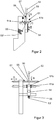
- FIG. 2 schematically shows a Hilfsfadenklemmwalzenplo 51 of an embodiment of a device 1 according to the invention in a side view.
- FIG. 2 with the same reference numerals as in FIG. 1 designated elements correspond to those of Figure 1, which is why reference is made to the above description of these elements.
- the auxiliary thread 50 stored in the auxiliary thread storage unit 5 is fed to the auxiliary thread nipping roller pair 51 by means of an auxiliary thread delivery tube 53, whereby destruction of the auxiliary thread 50 during transportation can be largely eliminated.
- the shape, position and dimension of the auxiliary thread conveying tube 53 can be chosen specifically for this case.
- the auxiliary thread 50 issuing from the auxiliary thread conveying tube 53, before moving to the auxiliary thread clamping roller pair 51 downstream in the auxiliary thread conveying direction B. is fed through an arranged between the auxiliary thread conveying tube 53 and the auxiliary thread clamping roller pair 51 auxiliary thread guide means 56.
- the auxiliary thread guiding device 56 is part of a Hilfsfadenchangier adopted 57, by which the auxiliary thread 50 is perpendicular to the auxiliary yarn transport direction B laterally moved back and forth, causing the auxiliary thread 50 does not constantly with the same contact surfaces of the auxiliary thread nip rollers 51a, 51b of the Hilfsfadenklemmwalzenpases 51 comes into contact , A running in of the auxiliary thread clamping rollers 51a, 51b used can thus be avoided.
- the auxiliary thread nip roll pair 51 preferably has, as in FIG. 2 shown, two opposite, can be pressed against each other, opposing auxiliary thread clamping rollers 51a, 51b.
- a first of the two auxiliary thread clamping rollers 51a is fixedly mounted in the device 1
- the second auxiliary thread clamping roller 51b is provided in the apparatus 1 according to the invention such that it can be pressed against and released from the fixed first auxiliary thread clamping roller 51a.
- a spring-actuated pressing device 54 can be used, with which the second auxiliary thread clamping roller 51b can be pressed against the first auxiliary thread clamping roller 51a.
- the pressing device 54 can also be designed differently and can also be positioned hydraulically or pneumatically in addition to a mechanical actuation.
- Size, size, shape and texture of the auxiliary thread nip rollers 51a, 51b can be selected application specific.
- the first auxiliary thread nip roller 51a is profiled and the second auxiliary thread nip roller 51b is gummed.
- Such a configuration of the auxiliary thread clamping rollers 51a, 51b prevents the auxiliary thread 50 from slipping out of the gap between the auxiliary thread clamping rollers 51a, 51b and also permits gentle transport of the auxiliary thread 50.
- the second auxiliary thread clamping roller 51b can either be completely made of rubber or only have a rubber coating.
- the profile and material of the profiled auxiliary thread clamping roller 51a can be freely selected depending on the conditions of use of this auxiliary thread clamping roller 51a. For example, it is possible for the profiled auxiliary thread clamping roller 51a to have a serrated pattern or grooves introduced counter to the auxiliary thread transport direction B.
- the first auxiliary thread nip roller 51a is driven, with its rotation being transmitted to the non-driven second auxiliary thread nip roller 51b. Accordingly, the auxiliary thread clamping rollers 51a, 51b perform opposite rotational movements C, C '.
- both auxiliary thread clamping rollers 51a, 51b can also be driven, and these can either be driven independently of one another or can be coupled or coupled to one another. It is only essential here that the two auxiliary thread clamping rollers 51a, 51b are operated in opposite directions of rotation.
- the Hilfsfadenklemmwalzencru 51 is in the embodiment of FIG. 2 a deflection device 55 downstream, which directs the auxiliary thread 50 in the direction of the drafting system 6.
- the deflection device 55 prevents too abrupt deflection and thus damage to the auxiliary thread 50, whereby the process reliability of the device 1 according to the invention can be increased.
- the deflecting device 55 is formed as an optical thread sensor which serves to ensure the presence of the auxiliary thread 50 after the auxiliary thread nip roller 51.
- the auxiliary thread detection takes place at this point optically and not mechanically, so as not to raise the tension level of the thread tension of the auxiliary thread 50 after passing through the auxiliary thread 50 through the auxiliary thread nip roller 51.
- auxiliary thread 50 leaving the auxiliary thread pinch roller pair 51 and deflected by the deflecting device 55 is then transported by another auxiliary thread conveying tube 53 'to the drafting unit 6 or the spinneret device 70, thus enabling a particularly gentle and process-stable transport of the auxiliary thread 50.
- FIG. 3 schematically shows the in FIG. 2 illustrated Hilfsfadenklemmwalzenplo 51 in a front view, with the same reference numerals as in the previous figures denote the same elements, which is why reference is made at this point to their previous explanations.
- FIG. 3 11 shows the auxiliary thread 50 guided by the auxiliary thread conveying tube 53, the auxiliary thread clamping rollers 51a, 51b and the deflecting device 55 into the auxiliary thread conveying tube 53 '.
- FIG. 3 It can also be seen how the auxiliary thread 50 passes through the auxiliary thread switching device 57 having the auxiliary thread guiding device 56.
- the contact surface of the auxiliary yarn 50 with the surfaces of the auxiliary yarn nip rollers 51a, 51b can be varied, whereby a running in of the auxiliary yarn nip rollers 51a, 51b and their too rapid wear can be avoided.
- the passage of the auxiliary thread 50 through the auxiliary thread guiding device 56 of the auxiliary thread switching device 57 has been found to be particularly advantageous with respect to the movement of the auxiliary thread 50 along the surfaces of the auxiliary thread clamping rollers 51a, 51b, since the auxiliary thread 50 is thus controlled without slipping by means of the auxiliary thread switching device 57 can be moved.
- the speed of the auxiliary thread clamping rollers 51a, 5b and / or the movement of the auxiliary thread 50 by means of the Hilfsfadenchangier Anlagen 57 is adjustable via a device control 90. With the aid of this device control 90, the speed of the Endfadenklemmwalzenpases 71 and / or the pressure of the spinnerets 70a, 70b emerging compressed air and / or the speed of the rollers of the drafting 6 and / or the knitting speed of the knitting machine 2 can be adjusted.
- the auxiliary thread guiding device 56 is configured in the simplest embodiment as a bore in the auxiliary thread switching device 57 designed, for example, as a shaft, but may also be designed differently in other embodiments of the device 1 according to the invention.
Landscapes
- Engineering & Computer Science (AREA)
- Textile Engineering (AREA)
- Mechanical Engineering (AREA)
- Yarns And Mechanical Finishing Of Yarns Or Ropes (AREA)
- Spinning Or Twisting Of Yarns (AREA)
- Knitting Of Fabric (AREA)
- Knitting Machines (AREA)
Applications Claiming Priority (2)
| Application Number | Priority Date | Filing Date | Title |
|---|---|---|---|
| DE102015119039.7A DE102015119039A1 (de) | 2015-11-05 | 2015-11-05 | Vorrichtung und Verfahren zur Herstellung von Maschenware |
| PCT/IB2016/056621 WO2017077480A1 (de) | 2015-11-05 | 2016-11-03 | Vorrichtung und verfahren zur herstellung von maschenware |
Publications (2)
| Publication Number | Publication Date |
|---|---|
| EP3371360A1 EP3371360A1 (de) | 2018-09-12 |
| EP3371360B1 true EP3371360B1 (de) | 2019-06-26 |
Family
ID=57286759
Family Applications (1)
| Application Number | Title | Priority Date | Filing Date |
|---|---|---|---|
| EP16794745.6A Not-in-force EP3371360B1 (de) | 2015-11-05 | 2016-11-03 | Vorrichtung und verfahren zur herstellung von maschenware |
Country Status (8)
| Country | Link |
|---|---|
| US (1) | US20180320298A1 (ja) |
| EP (1) | EP3371360B1 (ja) |
| JP (1) | JP2018538452A (ja) |
| KR (1) | KR20180081118A (ja) |
| CN (1) | CN108291339A (ja) |
| DE (2) | DE202015009463U1 (ja) |
| TW (1) | TW201730395A (ja) |
| WO (1) | WO2017077480A1 (ja) |
Families Citing this family (5)
| Publication number | Priority date | Publication date | Assignee | Title |
|---|---|---|---|---|
| CN109736015B (zh) * | 2019-01-11 | 2020-10-27 | 宜宾海丝特纤维有限责任公司 | 一种多工位编绞方法 |
| CN110241510B (zh) * | 2019-07-12 | 2020-11-03 | 晋江传兴织造有限公司 | 一种吸湿排汗型丽心布的生产设备及其工艺 |
| JP6822708B1 (ja) * | 2020-03-25 | 2021-01-27 | 株式会社Itoi生活文化研究所 | 複合紙糸及び該製造装置並びに該製造方法 |
| CN113942886B (zh) * | 2020-07-16 | 2023-05-02 | Ykk株式会社 | 线状体供给装置 |
| CN112726045A (zh) * | 2021-01-20 | 2021-04-30 | 晋江市凌亚贸易有限公司 | 一种服装面料加工用线团固定装置及使用方法 |
Family Cites Families (16)
| Publication number | Priority date | Publication date | Assignee | Title |
|---|---|---|---|---|
| US2448217A (en) * | 1941-02-12 | 1948-08-31 | American Enka Corp | Thread guide |
| FR1465085A (fr) * | 1965-01-21 | 1967-01-06 | Zinser Textilmaschinen Gmbh | Banc d'étirage avec dispositif d'amenée d'un fil de fond |
| US3370410A (en) * | 1965-01-29 | 1968-02-27 | Caron Spinning Company | Spinning device |
| US4614081A (en) * | 1984-10-11 | 1986-09-30 | Youngnam Textile Co., Ltd. | Method for manufacturing a cotton yarn |
| JP3552618B2 (ja) * | 1999-12-13 | 2004-08-11 | 村田機械株式会社 | コアヤーン製造方法および装置 |
| JP2002317336A (ja) * | 2001-04-23 | 2002-10-31 | Kurabo Ind Ltd | 精紡装置及び交撚糸 |
| EP1599625B1 (de) * | 2003-03-06 | 2015-10-07 | König, Reinhard | Maschenware sowie verfahren und vorrichtung zu ihrer herstellung |
| DE102006037714A1 (de) | 2006-08-07 | 2008-02-14 | Wilhelm Stahlecker Gmbh | Vorrichtung zum Herstellen einer Maschenware |
| US20080299855A1 (en) * | 2007-05-31 | 2008-12-04 | Toshifumi Morihashi | Core yarn and woven and knitted fabric |
| DE102007027467A1 (de) * | 2007-06-14 | 2008-12-18 | König, Reinhard, Dr. Ing. | Maschine zum Spinnen und Stricken sowie ein Verfahren |
| TWI471469B (zh) | 2007-10-02 | 2015-02-01 | Rotorcraft Ag | 用於製造針織布的方法和裝置 |
| BRPI0818760A2 (pt) | 2007-11-06 | 2015-04-07 | Rotorcraft Ag | Máquina de malharia, e, método para gerar tecidos de malha a partir da mecha com uma máquina de malharia. |
| CN101665998B (zh) * | 2008-09-04 | 2013-04-03 | 东华大学 | 一种集聚复合纱的纺纱装置 |
| US8276358B2 (en) * | 2009-12-22 | 2012-10-02 | Ruentex Industries Limited | Process of manufacturing ultra-soft yarn and fabric thereof |
| DE102011053396B3 (de) * | 2011-09-08 | 2012-08-23 | Terrot Gmbh | Vorrichtung und Verfahren zur Herstellung von Maschenware |
| CN105002618A (zh) * | 2015-09-02 | 2015-10-28 | 福建华峰新材料有限公司 | 一种锦纶异收缩纱的包覆系统及其制备工艺 |
-
2015
- 2015-11-05 DE DE202015009463.5U patent/DE202015009463U1/de active Active
- 2015-11-05 DE DE102015119039.7A patent/DE102015119039A1/de not_active Ceased
-
2016
- 2016-11-02 TW TW105135563A patent/TW201730395A/zh unknown
- 2016-11-03 US US15/774,018 patent/US20180320298A1/en not_active Abandoned
- 2016-11-03 EP EP16794745.6A patent/EP3371360B1/de not_active Not-in-force
- 2016-11-03 KR KR1020187016068A patent/KR20180081118A/ko unknown
- 2016-11-03 CN CN201680071287.4A patent/CN108291339A/zh active Pending
- 2016-11-03 JP JP2018522755A patent/JP2018538452A/ja active Pending
- 2016-11-03 WO PCT/IB2016/056621 patent/WO2017077480A1/de active Application Filing
Non-Patent Citations (1)
| Title |
|---|
| None * |
Also Published As
| Publication number | Publication date |
|---|---|
| KR20180081118A (ko) | 2018-07-13 |
| CN108291339A (zh) | 2018-07-17 |
| DE102015119039A1 (de) | 2017-05-11 |
| US20180320298A1 (en) | 2018-11-08 |
| EP3371360A1 (de) | 2018-09-12 |
| DE202015009463U1 (de) | 2017-09-22 |
| WO2017077480A1 (de) | 2017-05-11 |
| JP2018538452A (ja) | 2018-12-27 |
| TW201730395A (zh) | 2017-09-01 |
Similar Documents
| Publication | Publication Date | Title |
|---|---|---|
| EP3371360B1 (de) | Vorrichtung und verfahren zur herstellung von maschenware | |
| DE102011053396B3 (de) | Vorrichtung und Verfahren zur Herstellung von Maschenware | |
| CH646117A5 (de) | Verfahren und einrichtung zum spleissen gesponnener garne an einer automatischen spulmaschine. | |
| DE102005009342A1 (de) | Aufspulmaschine | |
| DE19815053B4 (de) | Verfahren zum Herstellen eines Scheinzwirnes und Spinnmaschine hierfür | |
| DE19815050A1 (de) | Spinnmaschine mit einem eine Saugwalze aufweisenden Streckwerk | |
| DE3943600C2 (de) | Verfahren und Vorrichtung zur Herstellung eines Mehrfachfadens sowie Mehrfachfaden | |
| CH711736A1 (de) | Verfahren zur Herstellung von elastischem Coregarn mit einer Ringspinnmaschine. | |
| EP3140440B1 (de) | Textilmaschine sowie verfahren zum betrieb einer solchen | |
| DE3926227C2 (ja) | ||
| DE10251727A1 (de) | Verfahren und Vorrichtung zur Herstellung von Flyerlunte | |
| DE10236450A1 (de) | Spinnmaschine mit einem Mehrstufen-Verdichtungs-Streckwerk | |
| WO2006092176A1 (de) | Flyerloses spinnverfahren sowie vorrichtung mit einem streckwerk | |
| DE2953527C2 (de) | Verfahren und Vorrichtung zur Herstellung von Effektgarn | |
| EP2980284B1 (de) | Verfahren zur herstellung eines luftgesponnenen garnes | |
| EP3140232B1 (de) | Textilmaschine, die der herstellung von vorgarn dient, sowie verfahren zum betrieb einer solchen | |
| DE19815049B4 (de) | Verfahren zum Herstellen eines Garnes und Spinnmaschine hierfür | |
| DE102006062364A1 (de) | Vorrichtung zum Herstellen einer Maschenware | |
| EP2915767B1 (de) | Arbeitsstelle einer textilmaschine mit einer paraffinierungseinrichtung | |
| DE3822294A1 (de) | Verfahren zum wiederanspinnen eines doppelfadens an einem spinnaggregat einer spinnmaschine | |
| DE102008005379A1 (de) | Verfahren zum Herstellen von Feinstrumpfwaren | |
| DE10161419A1 (de) | Verfahren und Vorrichtung zur Herstellung eines Kombinationsgarnes | |
| DE861737C (de) | Verfahren und Vorrichtung zum Nacheinanderanzwirnen der einzelnen Faeden eines laufenden Fadenbuendels auf den Spindeln einer Ringzwirnmaschine | |
| DE3542423A1 (de) | Vorrichtung zum vorbereiten von fadenkomponenten fuer ein anschliessendes verzwirnen | |
| WO2023217322A1 (de) | Streckwerk, faserverarbeitungsmaschine mit streckwerk und verfahren zum betreiben eines streckwerks |
Legal Events
| Date | Code | Title | Description |
|---|---|---|---|
| STAA | Information on the status of an ep patent application or granted ep patent |
Free format text: STATUS: UNKNOWN |
|
| STAA | Information on the status of an ep patent application or granted ep patent |
Free format text: STATUS: THE INTERNATIONAL PUBLICATION HAS BEEN MADE |
|
| PUAI | Public reference made under article 153(3) epc to a published international application that has entered the european phase |
Free format text: ORIGINAL CODE: 0009012 |
|
| STAA | Information on the status of an ep patent application or granted ep patent |
Free format text: STATUS: REQUEST FOR EXAMINATION WAS MADE |
|
| 17P | Request for examination filed |
Effective date: 20180604 |
|
| AK | Designated contracting states |
Kind code of ref document: A1 Designated state(s): AL AT BE BG CH CY CZ DE DK EE ES FI FR GB GR HR HU IE IS IT LI LT LU LV MC MK MT NL NO PL PT RO RS SE SI SK SM TR |
|
| AX | Request for extension of the european patent |
Extension state: BA ME |
|
| DAV | Request for validation of the european patent (deleted) | ||
| DAX | Request for extension of the european patent (deleted) | ||
| GRAP | Despatch of communication of intention to grant a patent |
Free format text: ORIGINAL CODE: EPIDOSNIGR1 |
|
| STAA | Information on the status of an ep patent application or granted ep patent |
Free format text: STATUS: GRANT OF PATENT IS INTENDED |
|
| INTG | Intention to grant announced |
Effective date: 20190402 |
|
| GRAS | Grant fee paid |
Free format text: ORIGINAL CODE: EPIDOSNIGR3 |
|
| GRAA | (expected) grant |
Free format text: ORIGINAL CODE: 0009210 |
|
| STAA | Information on the status of an ep patent application or granted ep patent |
Free format text: STATUS: THE PATENT HAS BEEN GRANTED |
|
| AK | Designated contracting states |
Kind code of ref document: B1 Designated state(s): AL AT BE BG CH CY CZ DE DK EE ES FI FR GB GR HR HU IE IS IT LI LT LU LV MC MK MT NL NO PL PT RO RS SE SI SK SM TR |
|
| REG | Reference to a national code |
Ref country code: GB Ref legal event code: FG4D Free format text: NOT ENGLISH |
|
| REG | Reference to a national code |
Ref country code: CH Ref legal event code: EP |
|
| REG | Reference to a national code |
Ref country code: AT Ref legal event code: REF Ref document number: 1148388 Country of ref document: AT Kind code of ref document: T Effective date: 20190715 |
|
| REG | Reference to a national code |
Ref country code: DE Ref legal event code: R096 Ref document number: 502016005304 Country of ref document: DE |
|
| REG | Reference to a national code |
Ref country code: IE Ref legal event code: FG4D Free format text: LANGUAGE OF EP DOCUMENT: GERMAN |
|
| REG | Reference to a national code |
Ref country code: NL Ref legal event code: MP Effective date: 20190626 |
|
| PG25 | Lapsed in a contracting state [announced via postgrant information from national office to epo] |
Ref country code: AL Free format text: LAPSE BECAUSE OF FAILURE TO SUBMIT A TRANSLATION OF THE DESCRIPTION OR TO PAY THE FEE WITHIN THE PRESCRIBED TIME-LIMIT Effective date: 20190626 Ref country code: FI Free format text: LAPSE BECAUSE OF FAILURE TO SUBMIT A TRANSLATION OF THE DESCRIPTION OR TO PAY THE FEE WITHIN THE PRESCRIBED TIME-LIMIT Effective date: 20190626 Ref country code: LT Free format text: LAPSE BECAUSE OF FAILURE TO SUBMIT A TRANSLATION OF THE DESCRIPTION OR TO PAY THE FEE WITHIN THE PRESCRIBED TIME-LIMIT Effective date: 20190626 Ref country code: HR Free format text: LAPSE BECAUSE OF FAILURE TO SUBMIT A TRANSLATION OF THE DESCRIPTION OR TO PAY THE FEE WITHIN THE PRESCRIBED TIME-LIMIT Effective date: 20190626 Ref country code: SE Free format text: LAPSE BECAUSE OF FAILURE TO SUBMIT A TRANSLATION OF THE DESCRIPTION OR TO PAY THE FEE WITHIN THE PRESCRIBED TIME-LIMIT Effective date: 20190626 Ref country code: NO Free format text: LAPSE BECAUSE OF FAILURE TO SUBMIT A TRANSLATION OF THE DESCRIPTION OR TO PAY THE FEE WITHIN THE PRESCRIBED TIME-LIMIT Effective date: 20190926 |
|
| REG | Reference to a national code |
Ref country code: LT Ref legal event code: MG4D |
|
| PG25 | Lapsed in a contracting state [announced via postgrant information from national office to epo] |
Ref country code: RS Free format text: LAPSE BECAUSE OF FAILURE TO SUBMIT A TRANSLATION OF THE DESCRIPTION OR TO PAY THE FEE WITHIN THE PRESCRIBED TIME-LIMIT Effective date: 20190626 Ref country code: BG Free format text: LAPSE BECAUSE OF FAILURE TO SUBMIT A TRANSLATION OF THE DESCRIPTION OR TO PAY THE FEE WITHIN THE PRESCRIBED TIME-LIMIT Effective date: 20190926 Ref country code: GR Free format text: LAPSE BECAUSE OF FAILURE TO SUBMIT A TRANSLATION OF THE DESCRIPTION OR TO PAY THE FEE WITHIN THE PRESCRIBED TIME-LIMIT Effective date: 20190927 Ref country code: LV Free format text: LAPSE BECAUSE OF FAILURE TO SUBMIT A TRANSLATION OF THE DESCRIPTION OR TO PAY THE FEE WITHIN THE PRESCRIBED TIME-LIMIT Effective date: 20190626 |
|
| PG25 | Lapsed in a contracting state [announced via postgrant information from national office to epo] |
Ref country code: CZ Free format text: LAPSE BECAUSE OF FAILURE TO SUBMIT A TRANSLATION OF THE DESCRIPTION OR TO PAY THE FEE WITHIN THE PRESCRIBED TIME-LIMIT Effective date: 20190626 Ref country code: RO Free format text: LAPSE BECAUSE OF FAILURE TO SUBMIT A TRANSLATION OF THE DESCRIPTION OR TO PAY THE FEE WITHIN THE PRESCRIBED TIME-LIMIT Effective date: 20190626 Ref country code: EE Free format text: LAPSE BECAUSE OF FAILURE TO SUBMIT A TRANSLATION OF THE DESCRIPTION OR TO PAY THE FEE WITHIN THE PRESCRIBED TIME-LIMIT Effective date: 20190626 Ref country code: NL Free format text: LAPSE BECAUSE OF FAILURE TO SUBMIT A TRANSLATION OF THE DESCRIPTION OR TO PAY THE FEE WITHIN THE PRESCRIBED TIME-LIMIT Effective date: 20190626 Ref country code: SK Free format text: LAPSE BECAUSE OF FAILURE TO SUBMIT A TRANSLATION OF THE DESCRIPTION OR TO PAY THE FEE WITHIN THE PRESCRIBED TIME-LIMIT Effective date: 20190626 Ref country code: PT Free format text: LAPSE BECAUSE OF FAILURE TO SUBMIT A TRANSLATION OF THE DESCRIPTION OR TO PAY THE FEE WITHIN THE PRESCRIBED TIME-LIMIT Effective date: 20191028 |
|
| PGFP | Annual fee paid to national office [announced via postgrant information from national office to epo] |
Ref country code: DE Payment date: 20190826 Year of fee payment: 4 |
|
| PG25 | Lapsed in a contracting state [announced via postgrant information from national office to epo] |
Ref country code: IT Free format text: LAPSE BECAUSE OF FAILURE TO SUBMIT A TRANSLATION OF THE DESCRIPTION OR TO PAY THE FEE WITHIN THE PRESCRIBED TIME-LIMIT Effective date: 20190626 Ref country code: IS Free format text: LAPSE BECAUSE OF FAILURE TO SUBMIT A TRANSLATION OF THE DESCRIPTION OR TO PAY THE FEE WITHIN THE PRESCRIBED TIME-LIMIT Effective date: 20191026 Ref country code: SM Free format text: LAPSE BECAUSE OF FAILURE TO SUBMIT A TRANSLATION OF THE DESCRIPTION OR TO PAY THE FEE WITHIN THE PRESCRIBED TIME-LIMIT Effective date: 20190626 Ref country code: ES Free format text: LAPSE BECAUSE OF FAILURE TO SUBMIT A TRANSLATION OF THE DESCRIPTION OR TO PAY THE FEE WITHIN THE PRESCRIBED TIME-LIMIT Effective date: 20190626 |
|
| PG25 | Lapsed in a contracting state [announced via postgrant information from national office to epo] |
Ref country code: TR Free format text: LAPSE BECAUSE OF FAILURE TO SUBMIT A TRANSLATION OF THE DESCRIPTION OR TO PAY THE FEE WITHIN THE PRESCRIBED TIME-LIMIT Effective date: 20190626 |
|
| PG25 | Lapsed in a contracting state [announced via postgrant information from national office to epo] |
Ref country code: DK Free format text: LAPSE BECAUSE OF FAILURE TO SUBMIT A TRANSLATION OF THE DESCRIPTION OR TO PAY THE FEE WITHIN THE PRESCRIBED TIME-LIMIT Effective date: 20190626 Ref country code: PL Free format text: LAPSE BECAUSE OF FAILURE TO SUBMIT A TRANSLATION OF THE DESCRIPTION OR TO PAY THE FEE WITHIN THE PRESCRIBED TIME-LIMIT Effective date: 20190626 |
|
| PG25 | Lapsed in a contracting state [announced via postgrant information from national office to epo] |
Ref country code: IS Free format text: LAPSE BECAUSE OF FAILURE TO SUBMIT A TRANSLATION OF THE DESCRIPTION OR TO PAY THE FEE WITHIN THE PRESCRIBED TIME-LIMIT Effective date: 20200320 |
|
| REG | Reference to a national code |
Ref country code: DE Ref legal event code: R097 Ref document number: 502016005304 Country of ref document: DE |
|
| REG | Reference to a national code |
Ref country code: CH Ref legal event code: PL |
|
| PLBE | No opposition filed within time limit |
Free format text: ORIGINAL CODE: 0009261 |
|
| STAA | Information on the status of an ep patent application or granted ep patent |
Free format text: STATUS: NO OPPOSITION FILED WITHIN TIME LIMIT |
|
| PG2D | Information on lapse in contracting state deleted |
Ref country code: IS |
|
| PG25 | Lapsed in a contracting state [announced via postgrant information from national office to epo] |
Ref country code: LI Free format text: LAPSE BECAUSE OF NON-PAYMENT OF DUE FEES Effective date: 20191130 Ref country code: LU Free format text: LAPSE BECAUSE OF NON-PAYMENT OF DUE FEES Effective date: 20191103 Ref country code: CH Free format text: LAPSE BECAUSE OF NON-PAYMENT OF DUE FEES Effective date: 20191130 Ref country code: MC Free format text: LAPSE BECAUSE OF FAILURE TO SUBMIT A TRANSLATION OF THE DESCRIPTION OR TO PAY THE FEE WITHIN THE PRESCRIBED TIME-LIMIT Effective date: 20190626 |
|
| 26N | No opposition filed |
Effective date: 20200603 |
|
| REG | Reference to a national code |
Ref country code: BE Ref legal event code: MM Effective date: 20191130 |
|
| PG25 | Lapsed in a contracting state [announced via postgrant information from national office to epo] |
Ref country code: SI Free format text: LAPSE BECAUSE OF FAILURE TO SUBMIT A TRANSLATION OF THE DESCRIPTION OR TO PAY THE FEE WITHIN THE PRESCRIBED TIME-LIMIT Effective date: 20190626 |
|
| PG25 | Lapsed in a contracting state [announced via postgrant information from national office to epo] |
Ref country code: IE Free format text: LAPSE BECAUSE OF NON-PAYMENT OF DUE FEES Effective date: 20191103 Ref country code: FR Free format text: LAPSE BECAUSE OF NON-PAYMENT OF DUE FEES Effective date: 20191130 |
|
| PG25 | Lapsed in a contracting state [announced via postgrant information from national office to epo] |
Ref country code: BE Free format text: LAPSE BECAUSE OF NON-PAYMENT OF DUE FEES Effective date: 20191130 |
|
| PG25 | Lapsed in a contracting state [announced via postgrant information from national office to epo] |
Ref country code: CY Free format text: LAPSE BECAUSE OF FAILURE TO SUBMIT A TRANSLATION OF THE DESCRIPTION OR TO PAY THE FEE WITHIN THE PRESCRIBED TIME-LIMIT Effective date: 20190626 |
|
| REG | Reference to a national code |
Ref country code: DE Ref legal event code: R119 Ref document number: 502016005304 Country of ref document: DE |
|
| GBPC | Gb: european patent ceased through non-payment of renewal fee |
Effective date: 20201103 |
|
| PG25 | Lapsed in a contracting state [announced via postgrant information from national office to epo] |
Ref country code: MT Free format text: LAPSE BECAUSE OF FAILURE TO SUBMIT A TRANSLATION OF THE DESCRIPTION OR TO PAY THE FEE WITHIN THE PRESCRIBED TIME-LIMIT Effective date: 20190626 Ref country code: HU Free format text: LAPSE BECAUSE OF FAILURE TO SUBMIT A TRANSLATION OF THE DESCRIPTION OR TO PAY THE FEE WITHIN THE PRESCRIBED TIME-LIMIT; INVALID AB INITIO Effective date: 20161103 |
|
| PG25 | Lapsed in a contracting state [announced via postgrant information from national office to epo] |
Ref country code: DE Free format text: LAPSE BECAUSE OF NON-PAYMENT OF DUE FEES Effective date: 20210601 Ref country code: GB Free format text: LAPSE BECAUSE OF NON-PAYMENT OF DUE FEES Effective date: 20201103 |
|
| PG25 | Lapsed in a contracting state [announced via postgrant information from national office to epo] |
Ref country code: MK Free format text: LAPSE BECAUSE OF FAILURE TO SUBMIT A TRANSLATION OF THE DESCRIPTION OR TO PAY THE FEE WITHIN THE PRESCRIBED TIME-LIMIT Effective date: 20190626 |
|
| REG | Reference to a national code |
Ref country code: AT Ref legal event code: MM01 Ref document number: 1148388 Country of ref document: AT Kind code of ref document: T Effective date: 20211103 |
|
| PG25 | Lapsed in a contracting state [announced via postgrant information from national office to epo] |
Ref country code: AT Free format text: LAPSE BECAUSE OF NON-PAYMENT OF DUE FEES Effective date: 20211103 |