EP3371035B1 - Dispositif d'assistance pour les manoeuvres d'accostage au niveau d'un quai - Google Patents
Dispositif d'assistance pour les manoeuvres d'accostage au niveau d'un quai Download PDFInfo
- Publication number
- EP3371035B1 EP3371035B1 EP16806230.5A EP16806230A EP3371035B1 EP 3371035 B1 EP3371035 B1 EP 3371035B1 EP 16806230 A EP16806230 A EP 16806230A EP 3371035 B1 EP3371035 B1 EP 3371035B1
- Authority
- EP
- European Patent Office
- Prior art keywords
- vehicle
- road
- steering
- rear wheels
- mode
- Prior art date
- Legal status (The legal status is an assumption and is not a legal conclusion. Google has not performed a legal analysis and makes no representation as to the accuracy of the status listed.)
- Active
Links
Images

Classifications
-
- B—PERFORMING OPERATIONS; TRANSPORTING
- B62—LAND VEHICLES FOR TRAVELLING OTHERWISE THAN ON RAILS
- B62D—MOTOR VEHICLES; TRAILERS
- B62D15/00—Steering not otherwise provided for
- B62D15/02—Steering position indicators ; Steering position determination; Steering aids
- B62D15/027—Parking aids, e.g. instruction means
-
- B—PERFORMING OPERATIONS; TRANSPORTING
- B60—VEHICLES IN GENERAL
- B60K—ARRANGEMENT OR MOUNTING OF PROPULSION UNITS OR OF TRANSMISSIONS IN VEHICLES; ARRANGEMENT OR MOUNTING OF PLURAL DIVERSE PRIME-MOVERS IN VEHICLES; AUXILIARY DRIVES FOR VEHICLES; INSTRUMENTATION OR DASHBOARDS FOR VEHICLES; ARRANGEMENTS IN CONNECTION WITH COOLING, AIR INTAKE, GAS EXHAUST OR FUEL SUPPLY OF PROPULSION UNITS IN VEHICLES
- B60K35/00—Instruments specially adapted for vehicles; Arrangement of instruments in or on vehicles
- B60K35/10—Input arrangements, i.e. from user to vehicle, associated with vehicle functions or specially adapted therefor
-
- B—PERFORMING OPERATIONS; TRANSPORTING
- B60—VEHICLES IN GENERAL
- B60Q—ARRANGEMENT OF SIGNALLING OR LIGHTING DEVICES, THE MOUNTING OR SUPPORTING THEREOF OR CIRCUITS THEREFOR, FOR VEHICLES IN GENERAL
- B60Q9/00—Arrangement or adaptation of signal devices not provided for in one of main groups B60Q1/00 - B60Q7/00, e.g. haptic signalling
-
- B—PERFORMING OPERATIONS; TRANSPORTING
- B60—VEHICLES IN GENERAL
- B60R—VEHICLES, VEHICLE FITTINGS, OR VEHICLE PARTS, NOT OTHERWISE PROVIDED FOR
- B60R16/00—Electric or fluid circuits specially adapted for vehicles and not otherwise provided for; Arrangement of elements of electric or fluid circuits specially adapted for vehicles and not otherwise provided for
- B60R16/02—Electric or fluid circuits specially adapted for vehicles and not otherwise provided for; Arrangement of elements of electric or fluid circuits specially adapted for vehicles and not otherwise provided for electric constitutive elements
- B60R16/037—Electric or fluid circuits specially adapted for vehicles and not otherwise provided for; Arrangement of elements of electric or fluid circuits specially adapted for vehicles and not otherwise provided for electric constitutive elements for occupant comfort, e.g. for automatic adjustment of appliances according to personal settings, e.g. seats, mirrors, steering wheel
- B60R16/0373—Voice control
-
- B—PERFORMING OPERATIONS; TRANSPORTING
- B62—LAND VEHICLES FOR TRAVELLING OTHERWISE THAN ON RAILS
- B62D—MOTOR VEHICLES; TRAILERS
- B62D15/00—Steering not otherwise provided for
- B62D15/02—Steering position indicators ; Steering position determination; Steering aids
- B62D15/021—Determination of steering angle
- B62D15/024—Other means for determination of steering angle without directly measuring it, e.g. deriving from wheel speeds on different sides of the car
-
- B—PERFORMING OPERATIONS; TRANSPORTING
- B62—LAND VEHICLES FOR TRAVELLING OTHERWISE THAN ON RAILS
- B62D—MOTOR VEHICLES; TRAILERS
- B62D7/00—Steering linkage; Stub axles or their mountings
- B62D7/06—Steering linkage; Stub axles or their mountings for individually-pivoted wheels, e.g. on king-pins
- B62D7/14—Steering linkage; Stub axles or their mountings for individually-pivoted wheels, e.g. on king-pins the pivotal axes being situated in more than one plane transverse to the longitudinal centre line of the vehicle, e.g. all-wheel steering
- B62D7/142—Steering linkage; Stub axles or their mountings for individually-pivoted wheels, e.g. on king-pins the pivotal axes being situated in more than one plane transverse to the longitudinal centre line of the vehicle, e.g. all-wheel steering specially adapted for particular vehicles, e.g. tractors, carts, earth-moving vehicles, trucks
-
- B—PERFORMING OPERATIONS; TRANSPORTING
- B62—LAND VEHICLES FOR TRAVELLING OTHERWISE THAN ON RAILS
- B62D—MOTOR VEHICLES; TRAILERS
- B62D7/00—Steering linkage; Stub axles or their mountings
- B62D7/06—Steering linkage; Stub axles or their mountings for individually-pivoted wheels, e.g. on king-pins
- B62D7/14—Steering linkage; Stub axles or their mountings for individually-pivoted wheels, e.g. on king-pins the pivotal axes being situated in more than one plane transverse to the longitudinal centre line of the vehicle, e.g. all-wheel steering
- B62D7/15—Steering linkage; Stub axles or their mountings for individually-pivoted wheels, e.g. on king-pins the pivotal axes being situated in more than one plane transverse to the longitudinal centre line of the vehicle, e.g. all-wheel steering characterised by means varying the ratio between the steering angles of the steered wheels
- B62D7/159—Steering linkage; Stub axles or their mountings for individually-pivoted wheels, e.g. on king-pins the pivotal axes being situated in more than one plane transverse to the longitudinal centre line of the vehicle, e.g. all-wheel steering characterised by means varying the ratio between the steering angles of the steered wheels characterised by computing methods or stabilisation processes or systems, e.g. responding to yaw rate, lateral wind, load, road condition
Definitions
- the present invention relates to a road vehicle comprising an assistance device for docking maneuvers at a platform.
- the invention relates to any type of articulated axle vehicle, more particularly a bus-type public transport road vehicle, comprising a device that assists the driver during approach and departure maneuvers of a platform so that the vehicle does not collide with its surroundings and is closer to the wharf at the end of the approach maneuver.
- This type of device is not suitable for driving in urban areas where it is particularly dangerous for the driver to leave his driving position.
- sensors or cameras are associated with electronic intelligence to control the front axle of the vehicle automatically.
- Anti-collision devices and trajectory correction devices are also known for vehicles whose wheels are the rear axle can be slightly steered, according to a steering angle whose absolute value is usually less than 2 °. This very limited steering angle does not help the driver for low speed berthing maneuvers.
- the object of the present invention is therefore to overcome the disadvantages of the prior art by proposing a new road vehicle comprising an assistance device for docking maneuvers at a dock.
- This assistance device is of automatic operation when it is switched on.
- the driver drives his vehicle in a conventional manner, by orienting the front steering axle in a conventional manner with his steering wheel, while the assistance device of the invention is concerned with orienting a rear axle which is modified so as to be director, without the driver having to worry about it.
- the wheels of the rear axle can be steered at an angle whose absolute value is much greater than 2 °, for example greater than 10 °, preferably greater than 20 ° and even more preferably greater than 30 °.
- Another object of the present invention is to provide a new method of docking at a dock for a road vehicle equipped with the assistance device of the invention.
- the assistance device controls the steering of the rear wheels fully automatically, so as to optimize and facilitate the various maneuvers performed by the driver when docking at a dock.
- the assistance device controls the turning of the rear wheels even more optimized to facilitate the various maneuvers performed by the driver when docking at a dock.
- the assistance device further comprises a distance sensor provided at the front of the vehicle for measuring the distance D AVenv from the front of the vehicle relative to the other obstacles of the vehicle. 'environment.
- the rear wheels can be steered at an angle whose absolute value is greater than 10 °, preferably greater than 20 ° and more preferably greater than 30 °.
- This steering angle much higher than that of existing rear axle steering, optimizes the different docking maneuvers compared to vehicles of the prior art.
- the steering control device controls the steering angle A AR of the rear wheels so that the rear wheels are at first straight and then, beyond a certain steering angle of the front wheels, the rear wheels are slaved in a proportional and linear manner with respect to the steering control received by the front wheels.
- the rear axle in road mode the rear axle is fixed with the rear wheels right when the vehicle speed is greater than the maximum speed of the road mode S VAR . This avoids any risk of dangerous behavior of the vehicle when it runs at a certain speed.
- the assistance device switches automatically from the docking mode to the road mode when the vehicle speed is greater than a maximum speed for docking V MAXaccostage or when the steering angle AT front wheels is greater than an angle ⁇ ExitMailing exit steering lock . This allows in particular to avoid any risk of dangerous behavior of the vehicle when it runs at a certain speed.
- the assistance device comprises sensors for measuring the steering angle A AV of the front wheels and the steering angle A AR of the rear wheels. These sensors provide information necessary for the operation of the assistance device, especially in road mode.
- the front axle comprises a steering box
- the steering angle A AV of the front wheels can be measured by an angle sensor which is connected to this steering box.
- the steering control device comprises a movable rod actuator
- the steering angle A AR of the rear wheels can be measured by a position sensor connected to the actuator of the steering device in the direction, the angle steering A AR rear wheels being calculated according to the position of the rod of the actuator.
- the distance sensors are provided on the right side of the vehicle, particularly in the case where the vehicle is intended to circulate on the right.
- the distance sensors provided at the front of the vehicle are provided in front of the front wheels
- the distance sensor at the platform provided at the rear of the vehicle is provided in front of the rear wheels
- the rear environmental sensor is provided at the rear of the rear wheels. This allows the sensors to be located closer to the obstacles they must detect.
- the distance information at the front and rear which are received by the distance sensors are transmitted to the driver visually, which helps him in his driving.
- the device of assistance includes a docking / road mode switch which switches the assistance device from the road mode to the docking mode and vice versa when it is activated.
- the docking mode / road mode switch can be actuated manually by the driver by means of a button provided in the driving position of the vehicle.
- the berthing / road mode switch can also be operated by a contactless dialogue between the infrastructure and the vehicle.
- the driver does not need to worry about operating the mode switch docking / road, this is done automatically for example when the vehicle approaches or away from a dock equipped with a dialogue device without contact with the vehicle.
- the docking mode / road mode switch does not make it possible to switch the assistance device from the road mode to the docking mode as long as the vehicle is traveling at a speed greater than the maximum speed for the docking V MAXaccostage . This avoids any risk of dangerous behavior of the vehicle when it runs at a certain speed.
- the assistance device also comprises an onboard intelligence that drives the steering device towards the rear axle.
- This embedded intelligence is for example connected to the distance sensors, the sensors for measuring the steering angle A AV of the front wheels and the steering angle A AR of the rear wheels, and the docking / road mode switch.
- the embedded intelligence may include a memory in which are stored the mathematical formulas used by the assistance device to control the steering angle of the rear wheels in road mode and in docking mode, as well as the values of the constants used in these formulas. .
- the rear wheels can be driven so as to be returned to the non-steered position. Indeed, this allows the vehicle to be closer to the dock, and steered wheels can sometimes interfere with the opening of the side doors of said vehicle.
- This process greatly facilitates docking maneuvers for the driver. This docking is thus optimized automatically by the assistance device, allowing the vehicle to dock in a parallel manner and close to a dock much easier, safer and a much shorter distance than with vehicles classics.
- the gap is reduced between the vehicle and the platform for easy access to the vehicle.
- the distance to the dock being controlled, the sides of the wheels do not come rubbing against the dock, which prevents their premature wear.
- the length necessary to achieve the docking is reduced, which allows the vehicle to dock even when the available space would be too low for a conventional vehicle.
- the invention By optimizing the time and the number of maneuvers necessary for a docking, the invention also makes it possible to optimize the fuel consumption of the vehicle.
- the sensors of the invention allow a visual assistance to driving that is independent of the weather and visibility.
- the assistance device (1) for the docking maneuvers at a platform (2) according to the invention is provided for a road vehicle (3) comprising a steering front axle (4) equipped with a steering wheel ( 6) conventional actuated by the steering wheel of the vehicle (3).
- the forward direction (6) is for example assisted by a variable power assisted hydraulic steering box (not shown).
- the assistance device (1) of the invention is preferably provided for a road transport vehicle (3), for example a bus, but it can be adapted to any type of road vehicle (3).
- the assistance device (1) according to the invention is also intended to operate the rear axle (5) of a road vehicle (3) in two modes, namely a road mode and a docking mode.
- the rear axle (5) is also steering and equipped with a steering (7), but it is not controlled by the driver of the road vehicle (3).
- the rear direction (7) is fully automatically controlled by the assistance device (1) according to the invention.
- the assistance device (1) comprises a steering device in the direction (10) of the rear axle (5).
- This steering device in direction (10) comprises an actuator, preferably in the form of a hydraulic cylinder associated with a proportional distributor, or in the form of an electric cylinder.
- the rear wheels (9) are at first straight and then, beyond a certain steering angle of the front wheels (11), the rear wheels (9) are slaved in a controlled manner. proportional to the steering control received by the front wheels (11).
- the rear wheels (9) are always straight, in the manner of a conventional vehicle.
- straight wheels wheels that are not steered, that is to say with a steering angle of 0 ° corresponding to wheels aligned in the longitudinal direction of the vehicle.
- the steering angle of the rear wheels (9) is controlled by the assistance device (1) as a function of the distances of the vehicle (3) in relation to the wharf (2) and other environmental obstacles.
- the rear axle (5) is provided for the normal driving of the vehicle (3) on the road (8), according to a maximum speed respecting the speed limits of the highway code.
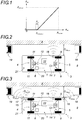
- the rear wheels (9) are slaved to the position of the front wheels (11) by a mathematical law taking into account the steering angle of the front wheels (11). This mathematical law governing the road mode is represented on the figure 1 .
- the vehicle (3) can travel at a speed the size of which is incompatible with the maneuvers required when docking at a platform (2).
- a speed of 50 km / h it is not possible for a vehicle (3) to dock at a platform at a speed of 50 km / h.
- the rear wheels (9) are straight until the front wheels (11) are pointed in one direction or the other beyond a certain angle, designated as the unlocking threshold S AR-unblock , from which the rear wheels (9) are automatically steered by the assistance device (1) of the invention at a steering angle proportional to that of the front wheels (11).
- the servo-control of the rear wheels (9) to the front wheels is progressively carried out, which results in a curve at the level of the transition between the right position of the rear wheels (9 ) and their enslaved position in steering.
- This transition is obtained by a polynomial law of degree 2.
- a steering angle of 0 for wheels corresponds to straight wheels, aligned along the longitudinal axis of the vehicle.
- the maximum turning angle A AR-max of the rear wheels (9) is intrinsically dependent on the vehicle (3) and its construction. It is usually between about -35 ° and + 35 °.
- the steering angle A AV of the front wheels (11) is preferably measured by an angle sensor (12) which is connected to the steering box (13) of the front axle (4), while the steering angle steering A AR rear wheels (9) is preferably measured by a position sensor (14) connected to the actuator of the steering device in the direction (10) to measure the linear displacement.
- a derivative integral proportional regulator PID
- the position sensor (14) calculates the steering angle A AR of the rear wheels (9) as a function of the position of the actuator rod.
- the steering angle A AV of the front wheels (11) is measured by an angle sensor which is housed in the pivot of at least one of the front wheels (11).
- the steering angle A AR of the rear wheels (9) is measured by an angle sensor which is housed in the pivot of at least one of the rear wheels (9).
- the angle range for the transition A Tr is between 0 ° and 40 °. By default, it is 6 ° but can be refined empirically by real-world tests for each type of vehicle (3).
- the release threshold S AR-unlocked rear wheels (9) is selected according to the degree of control desired for the rear axle (5).
- the lower this threshold S AR-deblock the more the driver may feel that the rear of the vehicle (3) "sweeps" too much.
- the higher this threshold S AR-unlocked the more the driving sensation approaches that of a conventional vehicle without assistance device (1) for the docking maneuvers and more the steering wheel movement is important.
- the release threshold S AR-unlocked rear wheels (9) is preferably chosen at 25%, but may for example be greater than 25%, the final value retained can be obtained empirically by real-world tests for each type of vehicle (3).
- the maximum speed of the road mode S VAR represents the maximum speed beyond which the rear axle (5) is fixed with the right rear wheels (9) (0 °) when the assistance device (1) is in the operating mode. road. Indeed, beyond a certain speed of the vehicle (3), it is considered that it would be dangerous for the rear axle (5) to be steered as this could cause instability of the vehicle (3) at the level of the vehicle. back when the driver takes a turn.
- the maximum speed of the S VAR road mode is 40 km / h by default in urban areas, but can be empirically refined by real-life tests for each type of vehicle (3) taking into account the specificities of the route on which it is intended to circulate.
- the slope of the servo-speed is between -1 and 0. By default it is equal to -0.1 but can be refined empirically by real-world tests for each type of vehicle (3).
- the rear axle (5) In docking mode, the rear axle (5) is provided to facilitate the docking of a vehicle (3) at a reduced speed at a platform (2). In this mode, the turning of the wheels (9) of the rear axle (5) is automatically controlled by the assistance device (1) according to the invention, with a important angle for optimizing the docking of the vehicle (3) at the dock (2).
- the vehicle (3) In docking mode, the vehicle (3) must travel at a reduced speed that is compatible with the maneuvers required when docking at a platform (2). Indeed, when a vehicle docked at a platform, it usually rolls slowly so as not to collide with its environment.
- This reduced speed also makes it possible to secure the assistance device (1) in the event of a malfunction.
- the assistance device (1) comprises various sensors that make it possible to locate the vehicle (3) with respect to its environment, particularly with respect to the other vehicles, and with respect to the platform (2) at which the driver wishes to dock.
- platforms are not equipped with specific borders and that in this case it is the sidewalk that serves as dock (2).
- a platform may be the same height as a sidewalk and it is not possible to distinguish platform (2) and sidewalk in terms of height.
- the sidewalk may be located higher or lower than the platform (2).
- the assistance device (1) comprises at least one distance sensor (16) located at the rear of the vehicle (3) and provided for detecting and measuring specifically the distance D ARquai from the rear of the vehicle (3) to the pier (2).
- the assistance device (1) also comprises at least one distance sensor (17) located at the front and at least one distance sensor (18) located at the rear, each being provided for detecting and measuring the distance D AVenv , D ARenv to other environmental obstacles (cars, pedestrians, etc.).
- the assistance device (1) also comprises at least one distance sensor (15) situated at the front of the vehicle (3) and designed to specifically detect and measure the distance D AVquai at platform (2) at the front of the vehicle (3).
- the distance sensor (17) to the environment located at the front can be optional because the assistance device (1) according to the invention does not take into account this distance to control the steering of the rear wheels (9) and the driver does not need this information if the visibility is good because he can estimate it himself from his driving position.
- the distance sensors (15, 16, 17, 18) can be of any type. It can thus be radar, laser, infra-red, ultrasonic or optical devices, such as cameras.
- the distance sensors (15, 16) at the platform can also be provided for measuring the height of the obstacles, in particular the height of the wharf (2). This makes it possible, for example, in the case of public transport vehicles, to adjust the height of the vehicle (3) according to that of the platform (2) so that the floor of the vehicle (3) is at the same level as that of the vehicle. from the dock (2).
- the vehicle (3) can adjust its height and / or deploy a ramp when necessary to facilitate the ascent and descent of passengers.
- This adjustment of the height of the vehicle (3) is for example performed by acting on the suspensions thereof.
- the height adjustment of the vehicle (3) can be automatic during the stopping phase of the vehicle (3) and / or be triggered manually by the driver or the users, for example by means of a button located at the outside of the vehicle so as to be accessible for a disabled person in a wheelchair.
- the distance sensors (15, 17) provided at the front of the vehicle (3) in addition to measuring the distance D AVquai from the front of the vehicle (3). ) relative to the platform (2) and the distance D AVenv from the front of the vehicle (3) with respect to other obstacles in the environment to control the steering of the rear wheels (9) in an optimized manner, also provide assistance to driving for the driver. Indeed, by a progressive feedback, preferably visual, the driver can optimize the placement of the front wheels (11) he directs with the vehicle steering wheel (3).
- the driver also receives information concerning the steering angle A AR.
- the same distance sensor can fulfill both the function of a distance sensor (15, 16) intended to detect and measure specifically the distance D ARquai , D AVquai at the platform (2) and that of a sensor (17, 18) intended to detect and measure the distance D ARenv , D AVenv to other obstacles in the environment.
- the sensors (15, 16) intended to detect and measure the distance D ARquai , D AVquai at the platform (2) are not necessarily located at the same height. on the vehicle (3) that the sensors (17, 18) provided for detecting and measuring the distance D ARenv , D AVenv to other obstacles in the environment.
- the distance sensors (15, 16) provided for specifically detecting and measuring the distance D ARquai , D AVquai at the platform (2) can be provided at a lower level than the distance sensors (17, 18) provided for detecting and measure the distance D ARenv , D AVenv to other obstacles in the environment.
- certain environmental obstacles such as the underside of a car (19) located on the floor (8) for example, may be located higher than the platform (2), but without touching the ground and would not be detected by a distance sensor located too low, while other obstacles in the environment could be located lower than the dock (2) and would not be detected by a distance sensor located too high.
- the sensors (15, 16, 17, 18), for example by providing distance sensors (17, 18) to the environment and / or distance sensors. (15, 16) at the platform provided both at the front and at the rear of the wheels (9, 11) of the vehicle (3).
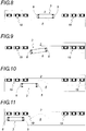
- the distance sensors (15, 16, 17, 18) of the invention are provided on the right side of the vehicle (3).
- the front distance sensors (15, 17) of the invention are provided in front of the front wheels (11), while the rear distance sensor at the platform (16) is provided in front of the rear wheels (9) and the distance sensor to the rear environment (18) is provided behind the rear wheels (9).
- the distance sensors at the platform (15, 16) are preferably provided in front of the wheels (9, 11) because the approaching of the vehicle (3) is generally in the forward direction.
- the distance sensors to the environment (17, 18) are preferably located at the front and rear ends of the vehicle (3) to be located closer to the obstacles of the environment they must detect.
- a second optional sensor (not shown) of the same type can be installed at the front of the rear wheels (9) so as to improve the detection accuracy of the environment.
- the distance sensors (15, 16, 17, 18) are provided on the vehicle (3) so as to detect and locate the obstacles as effectively as possible so that the road vehicle (3) does not collide with its environment, and that, during the approach phase of the platform (2), the steering angle A AR of the rear wheels (9) is optimized so that the wheels (9, 11) of the vehicle (3) n 'do not collide with the platform (2), the rear of the vehicle (3) does not approach the platform (2) faster than the front of the vehicle (3) and the vehicle (3) found parallel to the wharf (2) at the end of the approach phase, with the front (6) and rear (5) axles located closest to the wharf (2).
- the distance information received by the distance sensors (15, 16, 17, 18) at the front and rear of the vehicle (3) is transmitted to the driver, preferably visually, and not audibly. because of the ambient noise usually encountered in public transport vehicles. The driver thus knows in real time the positioning of his vehicle (3) relative to the dock (2) and the environment.
- the distance sensors D AVquai , D ARquai , D AVenv and D ARenv are preferably provided with a detection range of between 0 and 1.5 meters.
- the assistance device (1) also comprises a docking / road mode switch (20) which switches the assistance device (1) from the road mode to the docking mode. and vice versa when activated.
- This docking / road mode switch (20) is preferably manually operated by means of a button (21) provided in the driving position of the vehicle (3), thus allowing the driver to switch himself the assistance device (1) of the road mode in docking mode and vice versa.
- this docking / road mode switch (20) can also be actuated by a contactless dialogue between the infrastructure (ground, platform, beacon, etc.) and the vehicle (3).
- this docking / road mode switch (20) does not make it possible to switch the assistance device (1) from the road mode to the docking mode as long as the vehicle is traveling at a speed which corresponds to that of a road mode. Indeed, the assistance device (1) can not be accidentally switched from road mode to docking mode when the vehicle is traveling at a speed where it would be dangerous, and the assistance device (1) automatically switches to road mode in case of exceeding this speed.
- the docking / road mode switch (20) does not allow to switch to docking mode as the vehicle is traveling at a speed greater than the maximum speed for docking MAXABostage V.
- the assistance device (1) automatically switches to road mode.
- This maximum speed for docking MAXABostage is by default 25 km / h, but it can be refined empirically by real-life tests for each type of vehicle, depending on the specificities of the environment in which it is located. expected that it circulates.
- the assistance device (1) also comprises an embedded intelligence (22), which is in particular connected to all the sensors (12, 14, 15, 16, 17, 18) of the invention, to the device steering in the direction (10) of the rear axle (5) and at the docking / road mode switch (20).
- an embedded intelligence 22
- the assistance device (1) also comprises an embedded intelligence (22), which is in particular connected to all the sensors (12, 14, 15, 16, 17, 18) of the invention, to the device steering in the direction (10) of the rear axle (5) and at the docking / road mode switch (20).
- This embedded intelligence (22) comprises in particular a memory (not shown) in which are stored the mathematical formulas used by the assistance device (1) according to the invention, as well as the values of the constants used in these formulas.
- a memory not shown
- means are provided to be able to seize and modify these mathematical formulas and these constants in the embedded intelligence (22), whether directly or remotely.
- the embedded intelligence (22) may include means (not shown) for transmitting information to the driver, preferably visually.
- the assistance device (1) also comprises a monitoring device (not shown) of the rear axle (5), designed to detect any anomaly at the level thereof, for example a electronics failure, hydraulic failure, general malfunction, inconsistency, etc.
- a monitoring device not shown
- the rear axle (5) is put in the safety position, fixing the rear wheels (9) in their central position, parallel to the longitudinal axis of the vehicle.
- the first variant of the invention which comprises for example only one distance sensor (16) at the platform (2) situated at the rear of the vehicle (3)
- the second variant of the invention which includes many other distance sensors (15, 17, 18)
- the first variant of the invention is therefore less expensive than the second, but it also provides assistance less optimized for the driver during his approach and departure maneuvers of a platform (2).
- the assistance device (1) When the vehicle (3) is traveling at a normal speed, to move quickly from one place to another, the assistance device (1) according to the invention is switched to road mode.
- the rear wheels (9) are straight, as in a conventional vehicle ( figure 4 ), or slaved in position relative to the front wheels (11) if the driver steers the front wheels (11) beyond a certain steering angle S AR-unlocked .
- the driver drives his vehicle (3) at a reduced speed and the assistance device (1) according to the invention is switched to docking mode.
- the approach phase is initiated when the vehicle is traveling at a speed below the maximum speed for the docking MAXABostage and the docking mode / road mode switch (20) has been manually actuated by the driver to switch the vehicle. assistance device (1) of the road mode in docking mode.
- the rear axle (5) is slaved so that it approaches closer to the platform (2) until the rear distance sensor (16) has detected the platform (2) ( Figures 4 and 5 ).
- the angular ratio R dockingSimpl is preferably between 0 and 10. Its default value is equal to 2, but it can be adjusted empirically by real-world tests for each type of vehicle.
- the rear axle (5) When the rear distance sensor (16) detects the platform (2), the rear axle (5) is driven in docking mode and the rear wheels (9) are steered so that the rear axle (5) reaches the maximum near the wharf (2) without colliding with it ( figure 6 ). This operation can cause the vehicle (3) to move crab.
- the steering of the rear wheels (9) is adapted according to the distance D ARquai of the rear of the vehicle (3) with respect to the platform (2), so that the wheels (9, 11) of the vehicle (3) do not collide with the platform (2).
- D ARquai is a polynomial law of degree 2 of type: at quaiAR * x 2 + b quaiAR * x + vs quaiAR
- the factors of the above formula can be empirically adjusted by real-life tests for each type of vehicle (3) taking into account the specificities of the type of place where it performs its docking maneuvers.
- the driver drives his vehicle (3) at a reduced speed and the assistance device (1) according to the invention is switched to docking mode.
- the wheels of the rear axle (5) remain driven in road mode as long as the front distance sensor (15) has not detected the platform (2) ( figure 5 ).
- This operation can cause the vehicle (3) to move crab if the environment allows it, or to move more conventionally in case of obstacle to avoid.
- f (D ARenv ) is a polynomial law of degree 2 of type: at ca. * x 2 + b ca. * x + vs ca.
- D ARquai is a polynomial law of degree 2 of type: at quaiAR * x 2 + b quaiAR * x + vs quaiAR
- D AVquai is a polynomial law of degree 1 of type: at quaiAV * D AVquai - D arched + b quaiAV
- the driver authorizes the opening of the doors.
- the rear wheels (9) are preferably controlled so as to be straight so as to be located closer to the platform (2), but this can increase the wear of the tires, also this orientation right rear wheels (9) can be optional.
- the vehicle (3) is located closer to the platform (2), both at the front and at the rear, so as to facilitate the ascent and descent of the passengers ( figure 7 ).
- the vehicle (3) can leave the dock (2).
- the rear axle (5) remains locked with the rear wheels (9) preferably in the upright position as the doors are not locked.
- the assistance device (1) according to the invention is then switched to docking mode.
- the assistance device (1) of the invention prohibits the rear axle (5) to steer the rear wheels (9) towards the dock (2).
- k start is chosen with a value equal to 20%. As before, this value can be refined empirically.
- the rear wheels (9) are not steered proportionally to the steering control received by the wheels (11) of the front axle (4), but steered according to a fixed steering angle, for example equal to 5 ° to the left.
- the rear wheels (9) are turned in the same way as during the approach phase but in a reverse manner.
- the rear axle (5) leaves the platform (2) as quickly as possible without ever colliding with its environment and without moving away from the platform (2) faster than the front axle (6).
- the tilting of the assistance device (1) of the invention in road mode can be done manually by the driver by means of the docking / road mode switch (20). ), automatically when the vehicle speed (3) is greater than the maximum speed for docking V MAXoading (default is 10 km / h) or automatically when the steering angle A AV on the right of the front wheels (11 ) is greater than an angle ⁇ ExitMessage exit steering port .
- the angle ⁇ ExitMessage exit steering bend can be expressed as an absolute angle or as a percentage of the angle A AV-max of maximum steering of the front wheels (11). This ⁇ - exit angle is preferably equal to 5 ° to the right, this value being able to be refined empirically.
- the assistance device (1) for docking maneuvers at a platform (2) according to the first variant of the invention is also intended to be used during a reverse gear of the vehicle (3) which is equipped, for all driving modes of the rear axle (5).
- the assistance device (1) In the driving phase, the assistance device (1) is in road mode and no modification of the driving law is necessary.
- the piloting law is not modified.
- the piloting law is reversed, that is to say that the rear wheels (9) are driven so as to approach the dock, without never collide with it.
- the assistance device (1) for docking maneuvers at a platform (2) according to the second variant of the invention is also provided during a reverse gear of the vehicle (3) which is equipped with it, for all the driving modes of the rear axle (5).
- the assistance device (1) In the driving phase, the assistance device (1) is in road mode and no modification of the driving law is necessary.
Landscapes
- Engineering & Computer Science (AREA)
- Mechanical Engineering (AREA)
- Chemical & Material Sciences (AREA)
- Combustion & Propulsion (AREA)
- Transportation (AREA)
- Mathematical Physics (AREA)
- Physics & Mathematics (AREA)
- Theoretical Computer Science (AREA)
- Human Computer Interaction (AREA)
- Steering Control In Accordance With Driving Conditions (AREA)
- Steering-Linkage Mechanisms And Four-Wheel Steering (AREA)
- Power Steering Mechanism (AREA)
- Electric Propulsion And Braking For Vehicles (AREA)
Priority Applications (1)
| Application Number | Priority Date | Filing Date | Title |
|---|---|---|---|
| PL16806230T PL3371035T3 (pl) | 2015-11-03 | 2016-10-27 | Urządzenie wspomagające do manewrów parkowania wzdłuż platformy |
Applications Claiming Priority (2)
| Application Number | Priority Date | Filing Date | Title |
|---|---|---|---|
| FR1560531A FR3043049B1 (fr) | 2015-11-03 | 2015-11-03 | Dispositif d'assistance pour les manœuvres d'accostage au niveau d'un quai |
| PCT/FR2016/052788 WO2017077223A1 (fr) | 2015-11-03 | 2016-10-27 | Dispositif d'assistance pour les manoeuvres d'accostage au niveau d'un quai |
Publications (2)
| Publication Number | Publication Date |
|---|---|
| EP3371035A1 EP3371035A1 (fr) | 2018-09-12 |
| EP3371035B1 true EP3371035B1 (fr) | 2019-10-16 |
Family
ID=55646682
Family Applications (1)
| Application Number | Title | Priority Date | Filing Date |
|---|---|---|---|
| EP16806230.5A Active EP3371035B1 (fr) | 2015-11-03 | 2016-10-27 | Dispositif d'assistance pour les manoeuvres d'accostage au niveau d'un quai |
Country Status (18)
| Country | Link |
|---|---|
| US (1) | US20180319439A1 (pl) |
| EP (1) | EP3371035B1 (pl) |
| JP (1) | JP6845248B2 (pl) |
| KR (1) | KR20180093901A (pl) |
| CN (1) | CN108290608B (pl) |
| BR (1) | BR112018008871A2 (pl) |
| CA (1) | CA3003916A1 (pl) |
| CO (1) | CO2018005482A2 (pl) |
| EC (1) | ECSP18041810A (pl) |
| ES (1) | ES2765801T3 (pl) |
| FR (1) | FR3043049B1 (pl) |
| IL (1) | IL258948A (pl) |
| MX (1) | MX382874B (pl) |
| PL (1) | PL3371035T3 (pl) |
| PT (1) | PT3371035T (pl) |
| RU (1) | RU2719494C2 (pl) |
| SG (1) | SG11201803554SA (pl) |
| WO (1) | WO2017077223A1 (pl) |
Families Citing this family (8)
| Publication number | Priority date | Publication date | Assignee | Title |
|---|---|---|---|---|
| FR3072069B1 (fr) * | 2017-10-10 | 2019-09-20 | Commissariat A L'energie Atomique Et Aux Energies Alternatives | Procede de conduite automatique sous contrainte d'un vehicule, notamment d'un bus dans un centre de remisage, et dispositif mettant en œuvre un tel procede |
| JP7077739B2 (ja) * | 2018-04-11 | 2022-05-31 | 株式会社ジェイテクト | 四輪操舵装置 |
| JP7374602B2 (ja) * | 2019-03-29 | 2023-11-07 | 日立建機株式会社 | 作業車両 |
| CN111746393A (zh) * | 2019-03-29 | 2020-10-09 | 比亚迪股份有限公司 | 车辆控制方法、车辆控制装置和车辆 |
| CN112193243B (zh) * | 2020-10-20 | 2022-01-28 | 河北工业大学 | 一种基于避障系统的多转向模式控制方法 |
| RU202907U1 (ru) * | 2020-11-27 | 2021-03-12 | Акционерное общество "Автомобильный завод "УРАЛ" | Система следящего гидравлического привода заднего управляемого моста транспортного средства |
| CN113753032B (zh) * | 2021-10-20 | 2022-12-02 | 中国第一汽车股份有限公司 | 一种泊车控制方法、装置及系统 |
| CN119551061B (zh) * | 2024-12-10 | 2025-12-26 | 潍柴雷沃智慧农业科技股份有限公司 | 一种拖拉机四轮转向电液控制系统、方法、设备及介质 |
Citations (1)
| Publication number | Priority date | Publication date | Assignee | Title |
|---|---|---|---|---|
| EP2390163A1 (de) * | 2010-05-27 | 2011-11-30 | Audi AG | Verfahren und Vorrichtung zur Einstellung von Lenkwinkeln einer Allradlenkung für ein Kraftfahrzeug |
Family Cites Families (17)
| Publication number | Priority date | Publication date | Assignee | Title |
|---|---|---|---|---|
| JPS5981269A (ja) * | 1982-10-30 | 1984-05-10 | Mazda Motor Corp | 車両の4輪操舵装置 |
| JPS61135866A (ja) * | 1984-12-04 | 1986-06-23 | Daihatsu Motor Co Ltd | 四輪操舵装置 |
| JPS6331881A (ja) * | 1986-07-25 | 1988-02-10 | Nippon Denso Co Ltd | 車両用縦列駐車制御装置 |
| JPS63312270A (ja) * | 1987-06-15 | 1988-12-20 | Fuji Heavy Ind Ltd | 自動車の後輪操舵制御方法 |
| JPH02136377A (ja) * | 1988-11-18 | 1990-05-24 | Toyota Motor Corp | 前後輪操舵車の後輪操舵装置 |
| JPH0396482A (ja) * | 1989-09-08 | 1991-04-22 | Jidosha Kiki Co Ltd | 四輪操舵装置 |
| DE10128792B4 (de) * | 2001-05-08 | 2005-06-09 | Daimlerchrysler Ag | Kollisionsschutz für Fahrzeuge |
| US6804592B2 (en) * | 2001-10-18 | 2004-10-12 | Delphi Technologies, Inc. | Four wheel steering compensation for low coefficient of friction surface |
| US20060235590A1 (en) * | 2005-02-11 | 2006-10-19 | Farhad Bolourchi | Parking assist utilizing steering system |
| DE102005025203A1 (de) * | 2005-05-25 | 2006-12-07 | Valeo Schalter Und Sensoren Gmbh | Einparkverfahren zum Einparken eines Kraftfahrzeugs und Kraftfahrzeug |
| JP2007030700A (ja) * | 2005-07-27 | 2007-02-08 | Aisin Seiki Co Ltd | 駐車支援装置 |
| DE102006027114A1 (de) * | 2006-06-12 | 2007-12-13 | Robert Bosch Gmbh | Steuergerät und Verfahren zur Fahrerunterstützung |
| JP2008143430A (ja) * | 2006-12-12 | 2008-06-26 | Toyota Motor Corp | 駐車支援装置 |
| JP2008201178A (ja) * | 2007-02-16 | 2008-09-04 | Toyota Motor Corp | 駐車支援装置 |
| FR2916721B1 (fr) * | 2007-06-04 | 2009-07-31 | Renault Sas | Vehicule motorise a quatre roues comportant deux roues arrieres directrices. |
| CN102514620A (zh) * | 2011-11-24 | 2012-06-27 | 华南农业大学 | 拖拉机同辙转向机构及其转向方法 |
| RU2561188C2 (ru) * | 2013-12-31 | 2015-08-27 | Федеральное государственное бюджетное образовательное учреждение высшего профессионального образования "Московский автомобильно-дорожный государственный технический университет (МАДИ)" | Городская машина |
-
2015
- 2015-11-03 FR FR1560531A patent/FR3043049B1/fr not_active Expired - Fee Related
-
2016
- 2016-10-27 PT PT168062305T patent/PT3371035T/pt unknown
- 2016-10-27 CN CN201680069855.7A patent/CN108290608B/zh not_active Expired - Fee Related
- 2016-10-27 CA CA3003916A patent/CA3003916A1/fr not_active Abandoned
- 2016-10-27 EP EP16806230.5A patent/EP3371035B1/fr active Active
- 2016-10-27 ES ES16806230T patent/ES2765801T3/es active Active
- 2016-10-27 WO PCT/FR2016/052788 patent/WO2017077223A1/fr not_active Ceased
- 2016-10-27 SG SG11201803554SA patent/SG11201803554SA/en unknown
- 2016-10-27 PL PL16806230T patent/PL3371035T3/pl unknown
- 2016-10-27 US US15/772,927 patent/US20180319439A1/en not_active Abandoned
- 2016-10-27 BR BR112018008871-4A patent/BR112018008871A2/pt not_active Application Discontinuation
- 2016-10-27 JP JP2018541567A patent/JP6845248B2/ja not_active Expired - Fee Related
- 2016-10-27 RU RU2018120304A patent/RU2719494C2/ru active
- 2016-10-27 MX MX2018005303A patent/MX382874B/es unknown
- 2016-10-27 KR KR1020187015168A patent/KR20180093901A/ko not_active Withdrawn
-
2018
- 2018-04-26 IL IL258948A patent/IL258948A/en unknown
- 2018-05-25 CO CONC2018/0005482A patent/CO2018005482A2/es unknown
- 2018-06-01 EC ECIEPI201841810A patent/ECSP18041810A/es unknown
Patent Citations (1)
| Publication number | Priority date | Publication date | Assignee | Title |
|---|---|---|---|---|
| EP2390163A1 (de) * | 2010-05-27 | 2011-11-30 | Audi AG | Verfahren und Vorrichtung zur Einstellung von Lenkwinkeln einer Allradlenkung für ein Kraftfahrzeug |
Also Published As
| Publication number | Publication date |
|---|---|
| MX2018005303A (es) | 2018-08-15 |
| ECSP18041810A (es) | 2018-07-31 |
| CN108290608A (zh) | 2018-07-17 |
| JP2018536588A (ja) | 2018-12-13 |
| PT3371035T (pt) | 2020-01-22 |
| FR3043049A1 (fr) | 2017-05-05 |
| CN108290608B (zh) | 2021-08-17 |
| BR112018008871A2 (pt) | 2019-04-24 |
| CA3003916A1 (fr) | 2017-05-11 |
| JP6845248B2 (ja) | 2021-03-17 |
| MX382874B (es) | 2025-03-13 |
| ES2765801T3 (es) | 2020-06-11 |
| CO2018005482A2 (es) | 2018-08-10 |
| US20180319439A1 (en) | 2018-11-08 |
| IL258948A (en) | 2018-06-28 |
| EP3371035A1 (fr) | 2018-09-12 |
| RU2018120304A3 (pl) | 2020-02-28 |
| WO2017077223A1 (fr) | 2017-05-11 |
| KR20180093901A (ko) | 2018-08-22 |
| PL3371035T3 (pl) | 2020-05-18 |
| RU2719494C2 (ru) | 2020-04-20 |
| RU2018120304A (ru) | 2019-12-05 |
| FR3043049B1 (fr) | 2017-12-08 |
| SG11201803554SA (en) | 2018-05-30 |
Similar Documents
| Publication | Publication Date | Title |
|---|---|---|
| EP3371035B1 (fr) | Dispositif d'assistance pour les manoeuvres d'accostage au niveau d'un quai | |
| EP1892688B1 (fr) | Procédé de détermination de passage d'un véhicule dans un goulet | |
| FR2965778B1 (fr) | Dispositif et procede d'assistance d'un conducteur de vehicule pour une manoeuvre | |
| CA2901305C (fr) | Vehicule automobile routier attelable | |
| EP1268255B1 (fr) | Procede et dispositif pour la prise en charge du parcage en creneau de vehicules motorises | |
| FR3096327A1 (fr) | Appareil de contrôle de conduite pour véhicule | |
| CN105939920B (zh) | 主动转向系统和用于控制行驶的车辆的方法 | |
| EP3980308B1 (fr) | Procédé de calcul de la position latérale d'un véhicule automobile | |
| FR2976245A1 (fr) | Procede et dispositif pour determiner une trajectoire d'engagement dans un emplacement de stationnement | |
| EP3546312B1 (en) | Method and system for handling conditions of a road on which a vehicle travels | |
| WO2020099098A1 (fr) | Procédé et système d'évitement d'obstacles comprenant la commande des systèmes de braquage et de freinage différentiel | |
| FR2969098A1 (fr) | Procede et dispositif d'assistance du conducteur d'un vehicule | |
| FR2961462A1 (fr) | Systeme d'assistance aux manoeuvres de rangement a fonction automatique | |
| EP3115280B1 (fr) | Procédé de conduite automatique pour l'insertion et l'extraction d'un véhicule dans une station d'accueil, et dispositif de contrôle mettant en oeuvre un tel procédé | |
| EP3377386B1 (fr) | Procédé d'aide a la conduite d'un véhicule automobile | |
| FR3056803A1 (fr) | Dispositif d'aide a la conduite d'un vehicule par determination et affichage d'une distance d'adaptation de la vitesse dudit vehicule | |
| EP4028298A1 (fr) | Procédé de démarrage de conduite autonome d'un véhicule automobile | |
| FR2913798A1 (fr) | Procede de determination de passage d'un vehicule dans un goulet | |
| WO2024110258A1 (fr) | Procede d'assistance au pilotage d'un vehicule automobile pour le realigner parallelement a une trajectoire ideale, dispositif et vehicule associes | |
| WO2024184200A1 (fr) | Procédé de pilotage d'un véhicule automobile |
Legal Events
| Date | Code | Title | Description |
|---|---|---|---|
| STAA | Information on the status of an ep patent application or granted ep patent |
Free format text: STATUS: UNKNOWN |
|
| STAA | Information on the status of an ep patent application or granted ep patent |
Free format text: STATUS: THE INTERNATIONAL PUBLICATION HAS BEEN MADE |
|
| PUAI | Public reference made under article 153(3) epc to a published international application that has entered the european phase |
Free format text: ORIGINAL CODE: 0009012 |
|
| STAA | Information on the status of an ep patent application or granted ep patent |
Free format text: STATUS: REQUEST FOR EXAMINATION WAS MADE |
|
| 17P | Request for examination filed |
Effective date: 20180531 |
|
| AK | Designated contracting states |
Kind code of ref document: A1 Designated state(s): AL AT BE BG CH CY CZ DE DK EE ES FI FR GB GR HR HU IE IS IT LI LT LU LV MC MK MT NL NO PL PT RO RS SE SI SK SM TR |
|
| AX | Request for extension of the european patent |
Extension state: BA ME |
|
| DAV | Request for validation of the european patent (deleted) | ||
| DAX | Request for extension of the european patent (deleted) | ||
| GRAP | Despatch of communication of intention to grant a patent |
Free format text: ORIGINAL CODE: EPIDOSNIGR1 |
|
| STAA | Information on the status of an ep patent application or granted ep patent |
Free format text: STATUS: GRANT OF PATENT IS INTENDED |
|
| RIC1 | Information provided on ipc code assigned before grant |
Ipc: B60K 37/06 20060101ALI20190418BHEP Ipc: B62D 15/02 20060101ALI20190418BHEP Ipc: B60R 16/037 20060101ALI20190418BHEP Ipc: B62D 7/14 20060101ALI20190418BHEP Ipc: B60Q 9/00 20060101ALI20190418BHEP Ipc: B62D 7/15 20060101AFI20190418BHEP |
|
| INTG | Intention to grant announced |
Effective date: 20190522 |
|
| GRAS | Grant fee paid |
Free format text: ORIGINAL CODE: EPIDOSNIGR3 |
|
| GRAA | (expected) grant |
Free format text: ORIGINAL CODE: 0009210 |
|
| STAA | Information on the status of an ep patent application or granted ep patent |
Free format text: STATUS: THE PATENT HAS BEEN GRANTED |
|
| AK | Designated contracting states |
Kind code of ref document: B1 Designated state(s): AL AT BE BG CH CY CZ DE DK EE ES FI FR GB GR HR HU IE IS IT LI LT LU LV MC MK MT NL NO PL PT RO RS SE SI SK SM TR |
|
| REG | Reference to a national code |
Ref country code: GB Ref legal event code: FG4D Free format text: NOT ENGLISH |
|
| REG | Reference to a national code |
Ref country code: CH Ref legal event code: EP |
|
| REG | Reference to a national code |
Ref country code: DE Ref legal event code: R096 Ref document number: 602016022662 Country of ref document: DE |
|
| REG | Reference to a national code |
Ref country code: IE Ref legal event code: FG4D Free format text: LANGUAGE OF EP DOCUMENT: FRENCH |
|
| REG | Reference to a national code |
Ref country code: AT Ref legal event code: REF Ref document number: 1190993 Country of ref document: AT Kind code of ref document: T Effective date: 20191115 |
|
| REG | Reference to a national code |
Ref country code: HK Ref legal event code: DE Ref document number: 1259937 Country of ref document: HK |
|
| REG | Reference to a national code |
Ref country code: RO Ref legal event code: EPE |
|
| REG | Reference to a national code |
Ref country code: FI Ref legal event code: FGE |
|
| REG | Reference to a national code |
Ref country code: PT Ref legal event code: SC4A Ref document number: 3371035 Country of ref document: PT Date of ref document: 20200122 Kind code of ref document: T Free format text: AVAILABILITY OF NATIONAL TRANSLATION Effective date: 20200114 |
|
| REG | Reference to a national code |
Ref country code: CH Ref legal event code: NV Representative=s name: RENTSCH PARTNER AG, CH |
|
| REG | Reference to a national code |
Ref country code: SE Ref legal event code: TRGR |
|
| REG | Reference to a national code |
Ref country code: NL Ref legal event code: FP |
|
| REG | Reference to a national code |
Ref country code: NO Ref legal event code: T2 Effective date: 20191016 |
|
| REG | Reference to a national code |
Ref country code: LT Ref legal event code: MG4D |
|
| REG | Reference to a national code |
Ref country code: AT Ref legal event code: MK05 Ref document number: 1190993 Country of ref document: AT Kind code of ref document: T Effective date: 20191016 |
|
| REG | Reference to a national code |
Ref country code: GR Ref legal event code: EP Ref document number: 20200400133 Country of ref document: GR Effective date: 20200415 |
|
| PG25 | Lapsed in a contracting state [announced via postgrant information from national office to epo] |
Ref country code: LT Free format text: LAPSE BECAUSE OF FAILURE TO SUBMIT A TRANSLATION OF THE DESCRIPTION OR TO PAY THE FEE WITHIN THE PRESCRIBED TIME-LIMIT Effective date: 20191016 Ref country code: LV Free format text: LAPSE BECAUSE OF FAILURE TO SUBMIT A TRANSLATION OF THE DESCRIPTION OR TO PAY THE FEE WITHIN THE PRESCRIBED TIME-LIMIT Effective date: 20191016 Ref country code: AT Free format text: LAPSE BECAUSE OF FAILURE TO SUBMIT A TRANSLATION OF THE DESCRIPTION OR TO PAY THE FEE WITHIN THE PRESCRIBED TIME-LIMIT Effective date: 20191016 |
|
| PG25 | Lapsed in a contracting state [announced via postgrant information from national office to epo] |
Ref country code: IS Free format text: LAPSE BECAUSE OF FAILURE TO SUBMIT A TRANSLATION OF THE DESCRIPTION OR TO PAY THE FEE WITHIN THE PRESCRIBED TIME-LIMIT Effective date: 20200224 Ref country code: HR Free format text: LAPSE BECAUSE OF FAILURE TO SUBMIT A TRANSLATION OF THE DESCRIPTION OR TO PAY THE FEE WITHIN THE PRESCRIBED TIME-LIMIT Effective date: 20191016 Ref country code: RS Free format text: LAPSE BECAUSE OF FAILURE TO SUBMIT A TRANSLATION OF THE DESCRIPTION OR TO PAY THE FEE WITHIN THE PRESCRIBED TIME-LIMIT Effective date: 20191016 |
|
| REG | Reference to a national code |
Ref country code: ES Ref legal event code: FG2A Ref document number: 2765801 Country of ref document: ES Kind code of ref document: T3 Effective date: 20200611 |
|
| PG25 | Lapsed in a contracting state [announced via postgrant information from national office to epo] |
Ref country code: AL Free format text: LAPSE BECAUSE OF FAILURE TO SUBMIT A TRANSLATION OF THE DESCRIPTION OR TO PAY THE FEE WITHIN THE PRESCRIBED TIME-LIMIT Effective date: 20191016 |
|
| REG | Reference to a national code |
Ref country code: DE Ref legal event code: R097 Ref document number: 602016022662 Country of ref document: DE |
|
| PG2D | Information on lapse in contracting state deleted |
Ref country code: IS |
|
| PG25 | Lapsed in a contracting state [announced via postgrant information from national office to epo] |
Ref country code: DK Free format text: LAPSE BECAUSE OF FAILURE TO SUBMIT A TRANSLATION OF THE DESCRIPTION OR TO PAY THE FEE WITHIN THE PRESCRIBED TIME-LIMIT Effective date: 20191016 Ref country code: EE Free format text: LAPSE BECAUSE OF FAILURE TO SUBMIT A TRANSLATION OF THE DESCRIPTION OR TO PAY THE FEE WITHIN THE PRESCRIBED TIME-LIMIT Effective date: 20191016 Ref country code: MC Free format text: LAPSE BECAUSE OF FAILURE TO SUBMIT A TRANSLATION OF THE DESCRIPTION OR TO PAY THE FEE WITHIN THE PRESCRIBED TIME-LIMIT Effective date: 20191016 Ref country code: CZ Free format text: LAPSE BECAUSE OF FAILURE TO SUBMIT A TRANSLATION OF THE DESCRIPTION OR TO PAY THE FEE WITHIN THE PRESCRIBED TIME-LIMIT Effective date: 20191016 Ref country code: IS Free format text: LAPSE BECAUSE OF FAILURE TO SUBMIT A TRANSLATION OF THE DESCRIPTION OR TO PAY THE FEE WITHIN THE PRESCRIBED TIME-LIMIT Effective date: 20200216 |
|
| PLBE | No opposition filed within time limit |
Free format text: ORIGINAL CODE: 0009261 |
|
| STAA | Information on the status of an ep patent application or granted ep patent |
Free format text: STATUS: NO OPPOSITION FILED WITHIN TIME LIMIT |
|
| PG25 | Lapsed in a contracting state [announced via postgrant information from national office to epo] |
Ref country code: SM Free format text: LAPSE BECAUSE OF FAILURE TO SUBMIT A TRANSLATION OF THE DESCRIPTION OR TO PAY THE FEE WITHIN THE PRESCRIBED TIME-LIMIT Effective date: 20191016 Ref country code: SK Free format text: LAPSE BECAUSE OF FAILURE TO SUBMIT A TRANSLATION OF THE DESCRIPTION OR TO PAY THE FEE WITHIN THE PRESCRIBED TIME-LIMIT Effective date: 20191016 |
|
| 26N | No opposition filed |
Effective date: 20200717 |
|
| PG25 | Lapsed in a contracting state [announced via postgrant information from national office to epo] |
Ref country code: IE Free format text: LAPSE BECAUSE OF NON-PAYMENT OF DUE FEES Effective date: 20191027 |
|
| PG25 | Lapsed in a contracting state [announced via postgrant information from national office to epo] |
Ref country code: SI Free format text: LAPSE BECAUSE OF FAILURE TO SUBMIT A TRANSLATION OF THE DESCRIPTION OR TO PAY THE FEE WITHIN THE PRESCRIBED TIME-LIMIT Effective date: 20191016 |
|
| PG25 | Lapsed in a contracting state [announced via postgrant information from national office to epo] |
Ref country code: CY Free format text: LAPSE BECAUSE OF FAILURE TO SUBMIT A TRANSLATION OF THE DESCRIPTION OR TO PAY THE FEE WITHIN THE PRESCRIBED TIME-LIMIT Effective date: 20191016 |
|
| GBPC | Gb: european patent ceased through non-payment of renewal fee |
Effective date: 20201027 |
|
| PG25 | Lapsed in a contracting state [announced via postgrant information from national office to epo] |
Ref country code: MT Free format text: LAPSE BECAUSE OF FAILURE TO SUBMIT A TRANSLATION OF THE DESCRIPTION OR TO PAY THE FEE WITHIN THE PRESCRIBED TIME-LIMIT Effective date: 20191016 Ref country code: HU Free format text: LAPSE BECAUSE OF FAILURE TO SUBMIT A TRANSLATION OF THE DESCRIPTION OR TO PAY THE FEE WITHIN THE PRESCRIBED TIME-LIMIT; INVALID AB INITIO Effective date: 20161027 |
|
| PG25 | Lapsed in a contracting state [announced via postgrant information from national office to epo] |
Ref country code: GB Free format text: LAPSE BECAUSE OF NON-PAYMENT OF DUE FEES Effective date: 20201027 |
|
| PG25 | Lapsed in a contracting state [announced via postgrant information from national office to epo] |
Ref country code: TR Free format text: LAPSE BECAUSE OF FAILURE TO SUBMIT A TRANSLATION OF THE DESCRIPTION OR TO PAY THE FEE WITHIN THE PRESCRIBED TIME-LIMIT Effective date: 20191016 |
|
| PG25 | Lapsed in a contracting state [announced via postgrant information from national office to epo] |
Ref country code: MK Free format text: LAPSE BECAUSE OF FAILURE TO SUBMIT A TRANSLATION OF THE DESCRIPTION OR TO PAY THE FEE WITHIN THE PRESCRIBED TIME-LIMIT Effective date: 20191016 |
|
| PGFP | Annual fee paid to national office [announced via postgrant information from national office to epo] |
Ref country code: NL Payment date: 20231019 Year of fee payment: 8 |
|
| PGFP | Annual fee paid to national office [announced via postgrant information from national office to epo] |
Ref country code: LU Payment date: 20231019 Year of fee payment: 8 |
|
| PGFP | Annual fee paid to national office [announced via postgrant information from national office to epo] |
Ref country code: GR Payment date: 20231020 Year of fee payment: 8 |
|
| PGFP | Annual fee paid to national office [announced via postgrant information from national office to epo] |
Ref country code: ES Payment date: 20231227 Year of fee payment: 8 |
|
| PGFP | Annual fee paid to national office [announced via postgrant information from national office to epo] |
Ref country code: SE Payment date: 20231019 Year of fee payment: 8 Ref country code: RO Payment date: 20231019 Year of fee payment: 8 Ref country code: PT Payment date: 20231019 Year of fee payment: 8 Ref country code: NO Payment date: 20231025 Year of fee payment: 8 Ref country code: IT Payment date: 20231026 Year of fee payment: 8 Ref country code: FI Payment date: 20231020 Year of fee payment: 8 Ref country code: DE Payment date: 20231020 Year of fee payment: 8 Ref country code: CH Payment date: 20231101 Year of fee payment: 8 Ref country code: BG Payment date: 20231020 Year of fee payment: 8 |
|
| PGFP | Annual fee paid to national office [announced via postgrant information from national office to epo] |
Ref country code: PL Payment date: 20231020 Year of fee payment: 8 Ref country code: BE Payment date: 20231019 Year of fee payment: 8 |
|
| PGFP | Annual fee paid to national office [announced via postgrant information from national office to epo] |
Ref country code: FR Payment date: 20241030 Year of fee payment: 9 |
|
| REG | Reference to a national code |
Ref country code: DE Ref legal event code: R119 Ref document number: 602016022662 Country of ref document: DE |
|
| REG | Reference to a national code |
Ref country code: CH Ref legal event code: PL |
|
| REG | Reference to a national code |
Ref country code: SE Ref legal event code: EUG |
|
| REG | Reference to a national code |
Ref country code: NL Ref legal event code: MM Effective date: 20241101 |
|
| PG25 | Lapsed in a contracting state [announced via postgrant information from national office to epo] |
Ref country code: FI Free format text: LAPSE BECAUSE OF NON-PAYMENT OF DUE FEES Effective date: 20241027 |
|
| PG25 | Lapsed in a contracting state [announced via postgrant information from national office to epo] |
Ref country code: DE Free format text: LAPSE BECAUSE OF NON-PAYMENT OF DUE FEES Effective date: 20250501 |
|
| PG25 | Lapsed in a contracting state [announced via postgrant information from national office to epo] |
Ref country code: NO Free format text: LAPSE BECAUSE OF NON-PAYMENT OF DUE FEES Effective date: 20241031 |
|
| PG25 | Lapsed in a contracting state [announced via postgrant information from national office to epo] |
Ref country code: LU Free format text: LAPSE BECAUSE OF NON-PAYMENT OF DUE FEES Effective date: 20241027 Ref country code: NL Free format text: LAPSE BECAUSE OF NON-PAYMENT OF DUE FEES Effective date: 20241101 Ref country code: BE Free format text: LAPSE BECAUSE OF NON-PAYMENT OF DUE FEES Effective date: 20241031 |
|
| PG25 | Lapsed in a contracting state [announced via postgrant information from national office to epo] |
Ref country code: PT Free format text: LAPSE BECAUSE OF NON-PAYMENT OF DUE FEES Effective date: 20250429 |
|
| PG25 | Lapsed in a contracting state [announced via postgrant information from national office to epo] |
Ref country code: BG Free format text: LAPSE BECAUSE OF NON-PAYMENT OF DUE FEES Effective date: 20241027 Ref country code: GR Free format text: LAPSE BECAUSE OF NON-PAYMENT OF DUE FEES Effective date: 20250512 |
|
| PG25 | Lapsed in a contracting state [announced via postgrant information from national office to epo] |
Ref country code: CH Free format text: LAPSE BECAUSE OF NON-PAYMENT OF DUE FEES Effective date: 20241031 |
|
| PG25 | Lapsed in a contracting state [announced via postgrant information from national office to epo] |
Ref country code: RO Free format text: LAPSE BECAUSE OF NON-PAYMENT OF DUE FEES Effective date: 20241027 |
|
| REG | Reference to a national code |
Ref country code: BE Ref legal event code: MM Effective date: 20241031 |
|
| PG25 | Lapsed in a contracting state [announced via postgrant information from national office to epo] |
Ref country code: SE Free format text: LAPSE BECAUSE OF NON-PAYMENT OF DUE FEES Effective date: 20241028 Ref country code: IT Free format text: LAPSE BECAUSE OF NON-PAYMENT OF DUE FEES Effective date: 20241027 |
|
| REG | Reference to a national code |
Ref country code: ES Ref legal event code: FD2A Effective date: 20251205 |
|
| PG25 | Lapsed in a contracting state [announced via postgrant information from national office to epo] |
Ref country code: ES Free format text: LAPSE BECAUSE OF NON-PAYMENT OF DUE FEES Effective date: 20241028 |