EP3371035B1 - Device to assist with manoeuvres for parking alongside a platform - Google Patents
Device to assist with manoeuvres for parking alongside a platform Download PDFInfo
- Publication number
- EP3371035B1 EP3371035B1 EP16806230.5A EP16806230A EP3371035B1 EP 3371035 B1 EP3371035 B1 EP 3371035B1 EP 16806230 A EP16806230 A EP 16806230A EP 3371035 B1 EP3371035 B1 EP 3371035B1
- Authority
- EP
- European Patent Office
- Prior art keywords
- vehicle
- road
- steering
- rear wheels
- mode
- Prior art date
- Legal status (The legal status is an assumption and is not a legal conclusion. Google has not performed a legal analysis and makes no representation as to the accuracy of the status listed.)
- Active
Links
- 238000013459 approach Methods 0.000 claims description 25
- 230000006870 function Effects 0.000 claims description 6
- 238000000034 method Methods 0.000 claims description 6
- 230000000007 visual effect Effects 0.000 claims description 4
- 230000001419 dependent effect Effects 0.000 claims description 3
- 238000003032 molecular docking Methods 0.000 description 78
- 102220047090 rs6152 Human genes 0.000 description 8
- 238000012360 testing method Methods 0.000 description 8
- 230000002441 reversible effect Effects 0.000 description 5
- 230000007704 transition Effects 0.000 description 5
- 230000007613 environmental effect Effects 0.000 description 4
- 230000006399 behavior Effects 0.000 description 3
- 238000012937 correction Methods 0.000 description 2
- 238000001514 detection method Methods 0.000 description 2
- 230000007257 malfunction Effects 0.000 description 2
- 238000012986 modification Methods 0.000 description 2
- 230000004048 modification Effects 0.000 description 2
- 244000236931 Cydonia oblonga Species 0.000 description 1
- 101100536354 Drosophila melanogaster tant gene Proteins 0.000 description 1
- 238000010276 construction Methods 0.000 description 1
- 238000006073 displacement reaction Methods 0.000 description 1
- 239000000446 fuel Substances 0.000 description 1
- 238000012806 monitoring device Methods 0.000 description 1
- 230000003287 optical effect Effects 0.000 description 1
- 230000002028 premature Effects 0.000 description 1
- 230000008569 process Effects 0.000 description 1
- 230000000750 progressive effect Effects 0.000 description 1
- 230000000717 retained effect Effects 0.000 description 1
- 238000005096 rolling process Methods 0.000 description 1
- 230000035807 sensation Effects 0.000 description 1
- 239000000725 suspension Substances 0.000 description 1
- 230000001960 triggered effect Effects 0.000 description 1
Images

Classifications
-
- B—PERFORMING OPERATIONS; TRANSPORTING
- B62—LAND VEHICLES FOR TRAVELLING OTHERWISE THAN ON RAILS
- B62D—MOTOR VEHICLES; TRAILERS
- B62D15/00—Steering not otherwise provided for
- B62D15/02—Steering position indicators ; Steering position determination; Steering aids
- B62D15/027—Parking aids, e.g. instruction means
-
- B—PERFORMING OPERATIONS; TRANSPORTING
- B60—VEHICLES IN GENERAL
- B60K—ARRANGEMENT OR MOUNTING OF PROPULSION UNITS OR OF TRANSMISSIONS IN VEHICLES; ARRANGEMENT OR MOUNTING OF PLURAL DIVERSE PRIME-MOVERS IN VEHICLES; AUXILIARY DRIVES FOR VEHICLES; INSTRUMENTATION OR DASHBOARDS FOR VEHICLES; ARRANGEMENTS IN CONNECTION WITH COOLING, AIR INTAKE, GAS EXHAUST OR FUEL SUPPLY OF PROPULSION UNITS IN VEHICLES
- B60K35/00—Instruments specially adapted for vehicles; Arrangement of instruments in or on vehicles
- B60K35/10—Input arrangements, i.e. from user to vehicle, associated with vehicle functions or specially adapted therefor
-
- B—PERFORMING OPERATIONS; TRANSPORTING
- B60—VEHICLES IN GENERAL
- B60Q—ARRANGEMENT OF SIGNALLING OR LIGHTING DEVICES, THE MOUNTING OR SUPPORTING THEREOF OR CIRCUITS THEREFOR, FOR VEHICLES IN GENERAL
- B60Q9/00—Arrangement or adaptation of signal devices not provided for in one of main groups B60Q1/00 - B60Q7/00, e.g. haptic signalling
-
- B—PERFORMING OPERATIONS; TRANSPORTING
- B60—VEHICLES IN GENERAL
- B60R—VEHICLES, VEHICLE FITTINGS, OR VEHICLE PARTS, NOT OTHERWISE PROVIDED FOR
- B60R16/00—Electric or fluid circuits specially adapted for vehicles and not otherwise provided for; Arrangement of elements of electric or fluid circuits specially adapted for vehicles and not otherwise provided for
- B60R16/02—Electric or fluid circuits specially adapted for vehicles and not otherwise provided for; Arrangement of elements of electric or fluid circuits specially adapted for vehicles and not otherwise provided for electric constitutive elements
- B60R16/037—Electric or fluid circuits specially adapted for vehicles and not otherwise provided for; Arrangement of elements of electric or fluid circuits specially adapted for vehicles and not otherwise provided for electric constitutive elements for occupant comfort, e.g. for automatic adjustment of appliances according to personal settings, e.g. seats, mirrors, steering wheel
- B60R16/0373—Voice control
-
- B—PERFORMING OPERATIONS; TRANSPORTING
- B62—LAND VEHICLES FOR TRAVELLING OTHERWISE THAN ON RAILS
- B62D—MOTOR VEHICLES; TRAILERS
- B62D15/00—Steering not otherwise provided for
- B62D15/02—Steering position indicators ; Steering position determination; Steering aids
- B62D15/021—Determination of steering angle
- B62D15/024—Other means for determination of steering angle without directly measuring it, e.g. deriving from wheel speeds on different sides of the car
-
- B—PERFORMING OPERATIONS; TRANSPORTING
- B62—LAND VEHICLES FOR TRAVELLING OTHERWISE THAN ON RAILS
- B62D—MOTOR VEHICLES; TRAILERS
- B62D7/00—Steering linkage; Stub axles or their mountings
- B62D7/06—Steering linkage; Stub axles or their mountings for individually-pivoted wheels, e.g. on king-pins
- B62D7/14—Steering linkage; Stub axles or their mountings for individually-pivoted wheels, e.g. on king-pins the pivotal axes being situated in more than one plane transverse to the longitudinal centre line of the vehicle, e.g. all-wheel steering
- B62D7/142—Steering linkage; Stub axles or their mountings for individually-pivoted wheels, e.g. on king-pins the pivotal axes being situated in more than one plane transverse to the longitudinal centre line of the vehicle, e.g. all-wheel steering specially adapted for particular vehicles, e.g. tractors, carts, earth-moving vehicles, trucks
-
- B—PERFORMING OPERATIONS; TRANSPORTING
- B62—LAND VEHICLES FOR TRAVELLING OTHERWISE THAN ON RAILS
- B62D—MOTOR VEHICLES; TRAILERS
- B62D7/00—Steering linkage; Stub axles or their mountings
- B62D7/06—Steering linkage; Stub axles or their mountings for individually-pivoted wheels, e.g. on king-pins
- B62D7/14—Steering linkage; Stub axles or their mountings for individually-pivoted wheels, e.g. on king-pins the pivotal axes being situated in more than one plane transverse to the longitudinal centre line of the vehicle, e.g. all-wheel steering
- B62D7/15—Steering linkage; Stub axles or their mountings for individually-pivoted wheels, e.g. on king-pins the pivotal axes being situated in more than one plane transverse to the longitudinal centre line of the vehicle, e.g. all-wheel steering characterised by means varying the ratio between the steering angles of the steered wheels
- B62D7/159—Steering linkage; Stub axles or their mountings for individually-pivoted wheels, e.g. on king-pins the pivotal axes being situated in more than one plane transverse to the longitudinal centre line of the vehicle, e.g. all-wheel steering characterised by means varying the ratio between the steering angles of the steered wheels characterised by computing methods or stabilisation processes or systems, e.g. responding to yaw rate, lateral wind, load, road condition
Definitions
- the present invention relates to a road vehicle comprising an assistance device for docking maneuvers at a platform.
- the invention relates to any type of articulated axle vehicle, more particularly a bus-type public transport road vehicle, comprising a device that assists the driver during approach and departure maneuvers of a platform so that the vehicle does not collide with its surroundings and is closer to the wharf at the end of the approach maneuver.
- This type of device is not suitable for driving in urban areas where it is particularly dangerous for the driver to leave his driving position.
- sensors or cameras are associated with electronic intelligence to control the front axle of the vehicle automatically.
- Anti-collision devices and trajectory correction devices are also known for vehicles whose wheels are the rear axle can be slightly steered, according to a steering angle whose absolute value is usually less than 2 °. This very limited steering angle does not help the driver for low speed berthing maneuvers.
- the object of the present invention is therefore to overcome the disadvantages of the prior art by proposing a new road vehicle comprising an assistance device for docking maneuvers at a dock.
- This assistance device is of automatic operation when it is switched on.
- the driver drives his vehicle in a conventional manner, by orienting the front steering axle in a conventional manner with his steering wheel, while the assistance device of the invention is concerned with orienting a rear axle which is modified so as to be director, without the driver having to worry about it.
- the wheels of the rear axle can be steered at an angle whose absolute value is much greater than 2 °, for example greater than 10 °, preferably greater than 20 ° and even more preferably greater than 30 °.
- Another object of the present invention is to provide a new method of docking at a dock for a road vehicle equipped with the assistance device of the invention.
- the assistance device controls the steering of the rear wheels fully automatically, so as to optimize and facilitate the various maneuvers performed by the driver when docking at a dock.
- the assistance device controls the turning of the rear wheels even more optimized to facilitate the various maneuvers performed by the driver when docking at a dock.
- the assistance device further comprises a distance sensor provided at the front of the vehicle for measuring the distance D AVenv from the front of the vehicle relative to the other obstacles of the vehicle. 'environment.
- the rear wheels can be steered at an angle whose absolute value is greater than 10 °, preferably greater than 20 ° and more preferably greater than 30 °.
- This steering angle much higher than that of existing rear axle steering, optimizes the different docking maneuvers compared to vehicles of the prior art.
- the steering control device controls the steering angle A AR of the rear wheels so that the rear wheels are at first straight and then, beyond a certain steering angle of the front wheels, the rear wheels are slaved in a proportional and linear manner with respect to the steering control received by the front wheels.
- the rear axle in road mode the rear axle is fixed with the rear wheels right when the vehicle speed is greater than the maximum speed of the road mode S VAR . This avoids any risk of dangerous behavior of the vehicle when it runs at a certain speed.
- the assistance device switches automatically from the docking mode to the road mode when the vehicle speed is greater than a maximum speed for docking V MAXaccostage or when the steering angle AT front wheels is greater than an angle ⁇ ExitMailing exit steering lock . This allows in particular to avoid any risk of dangerous behavior of the vehicle when it runs at a certain speed.
- the assistance device comprises sensors for measuring the steering angle A AV of the front wheels and the steering angle A AR of the rear wheels. These sensors provide information necessary for the operation of the assistance device, especially in road mode.
- the front axle comprises a steering box
- the steering angle A AV of the front wheels can be measured by an angle sensor which is connected to this steering box.
- the steering control device comprises a movable rod actuator
- the steering angle A AR of the rear wheels can be measured by a position sensor connected to the actuator of the steering device in the direction, the angle steering A AR rear wheels being calculated according to the position of the rod of the actuator.
- the distance sensors are provided on the right side of the vehicle, particularly in the case where the vehicle is intended to circulate on the right.
- the distance sensors provided at the front of the vehicle are provided in front of the front wheels
- the distance sensor at the platform provided at the rear of the vehicle is provided in front of the rear wheels
- the rear environmental sensor is provided at the rear of the rear wheels. This allows the sensors to be located closer to the obstacles they must detect.
- the distance information at the front and rear which are received by the distance sensors are transmitted to the driver visually, which helps him in his driving.
- the device of assistance includes a docking / road mode switch which switches the assistance device from the road mode to the docking mode and vice versa when it is activated.
- the docking mode / road mode switch can be actuated manually by the driver by means of a button provided in the driving position of the vehicle.
- the berthing / road mode switch can also be operated by a contactless dialogue between the infrastructure and the vehicle.
- the driver does not need to worry about operating the mode switch docking / road, this is done automatically for example when the vehicle approaches or away from a dock equipped with a dialogue device without contact with the vehicle.
- the docking mode / road mode switch does not make it possible to switch the assistance device from the road mode to the docking mode as long as the vehicle is traveling at a speed greater than the maximum speed for the docking V MAXaccostage . This avoids any risk of dangerous behavior of the vehicle when it runs at a certain speed.
- the assistance device also comprises an onboard intelligence that drives the steering device towards the rear axle.
- This embedded intelligence is for example connected to the distance sensors, the sensors for measuring the steering angle A AV of the front wheels and the steering angle A AR of the rear wheels, and the docking / road mode switch.
- the embedded intelligence may include a memory in which are stored the mathematical formulas used by the assistance device to control the steering angle of the rear wheels in road mode and in docking mode, as well as the values of the constants used in these formulas. .
- the rear wheels can be driven so as to be returned to the non-steered position. Indeed, this allows the vehicle to be closer to the dock, and steered wheels can sometimes interfere with the opening of the side doors of said vehicle.
- This process greatly facilitates docking maneuvers for the driver. This docking is thus optimized automatically by the assistance device, allowing the vehicle to dock in a parallel manner and close to a dock much easier, safer and a much shorter distance than with vehicles classics.
- the gap is reduced between the vehicle and the platform for easy access to the vehicle.
- the distance to the dock being controlled, the sides of the wheels do not come rubbing against the dock, which prevents their premature wear.
- the length necessary to achieve the docking is reduced, which allows the vehicle to dock even when the available space would be too low for a conventional vehicle.
- the invention By optimizing the time and the number of maneuvers necessary for a docking, the invention also makes it possible to optimize the fuel consumption of the vehicle.
- the sensors of the invention allow a visual assistance to driving that is independent of the weather and visibility.
- the assistance device (1) for the docking maneuvers at a platform (2) according to the invention is provided for a road vehicle (3) comprising a steering front axle (4) equipped with a steering wheel ( 6) conventional actuated by the steering wheel of the vehicle (3).
- the forward direction (6) is for example assisted by a variable power assisted hydraulic steering box (not shown).
- the assistance device (1) of the invention is preferably provided for a road transport vehicle (3), for example a bus, but it can be adapted to any type of road vehicle (3).
- the assistance device (1) according to the invention is also intended to operate the rear axle (5) of a road vehicle (3) in two modes, namely a road mode and a docking mode.
- the rear axle (5) is also steering and equipped with a steering (7), but it is not controlled by the driver of the road vehicle (3).
- the rear direction (7) is fully automatically controlled by the assistance device (1) according to the invention.
- the assistance device (1) comprises a steering device in the direction (10) of the rear axle (5).
- This steering device in direction (10) comprises an actuator, preferably in the form of a hydraulic cylinder associated with a proportional distributor, or in the form of an electric cylinder.
- the rear wheels (9) are at first straight and then, beyond a certain steering angle of the front wheels (11), the rear wheels (9) are slaved in a controlled manner. proportional to the steering control received by the front wheels (11).
- the rear wheels (9) are always straight, in the manner of a conventional vehicle.
- straight wheels wheels that are not steered, that is to say with a steering angle of 0 ° corresponding to wheels aligned in the longitudinal direction of the vehicle.
- the steering angle of the rear wheels (9) is controlled by the assistance device (1) as a function of the distances of the vehicle (3) in relation to the wharf (2) and other environmental obstacles.
- the rear axle (5) is provided for the normal driving of the vehicle (3) on the road (8), according to a maximum speed respecting the speed limits of the highway code.
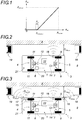
- the rear wheels (9) are slaved to the position of the front wheels (11) by a mathematical law taking into account the steering angle of the front wheels (11). This mathematical law governing the road mode is represented on the figure 1 .
- the vehicle (3) can travel at a speed the size of which is incompatible with the maneuvers required when docking at a platform (2).
- a speed of 50 km / h it is not possible for a vehicle (3) to dock at a platform at a speed of 50 km / h.
- the rear wheels (9) are straight until the front wheels (11) are pointed in one direction or the other beyond a certain angle, designated as the unlocking threshold S AR-unblock , from which the rear wheels (9) are automatically steered by the assistance device (1) of the invention at a steering angle proportional to that of the front wheels (11).
- the servo-control of the rear wheels (9) to the front wheels is progressively carried out, which results in a curve at the level of the transition between the right position of the rear wheels (9 ) and their enslaved position in steering.
- This transition is obtained by a polynomial law of degree 2.
- a steering angle of 0 for wheels corresponds to straight wheels, aligned along the longitudinal axis of the vehicle.
- the maximum turning angle A AR-max of the rear wheels (9) is intrinsically dependent on the vehicle (3) and its construction. It is usually between about -35 ° and + 35 °.
- the steering angle A AV of the front wheels (11) is preferably measured by an angle sensor (12) which is connected to the steering box (13) of the front axle (4), while the steering angle steering A AR rear wheels (9) is preferably measured by a position sensor (14) connected to the actuator of the steering device in the direction (10) to measure the linear displacement.
- a derivative integral proportional regulator PID
- the position sensor (14) calculates the steering angle A AR of the rear wheels (9) as a function of the position of the actuator rod.
- the steering angle A AV of the front wheels (11) is measured by an angle sensor which is housed in the pivot of at least one of the front wheels (11).
- the steering angle A AR of the rear wheels (9) is measured by an angle sensor which is housed in the pivot of at least one of the rear wheels (9).
- the angle range for the transition A Tr is between 0 ° and 40 °. By default, it is 6 ° but can be refined empirically by real-world tests for each type of vehicle (3).
- the release threshold S AR-unlocked rear wheels (9) is selected according to the degree of control desired for the rear axle (5).
- the lower this threshold S AR-deblock the more the driver may feel that the rear of the vehicle (3) "sweeps" too much.
- the higher this threshold S AR-unlocked the more the driving sensation approaches that of a conventional vehicle without assistance device (1) for the docking maneuvers and more the steering wheel movement is important.
- the release threshold S AR-unlocked rear wheels (9) is preferably chosen at 25%, but may for example be greater than 25%, the final value retained can be obtained empirically by real-world tests for each type of vehicle (3).
- the maximum speed of the road mode S VAR represents the maximum speed beyond which the rear axle (5) is fixed with the right rear wheels (9) (0 °) when the assistance device (1) is in the operating mode. road. Indeed, beyond a certain speed of the vehicle (3), it is considered that it would be dangerous for the rear axle (5) to be steered as this could cause instability of the vehicle (3) at the level of the vehicle. back when the driver takes a turn.
- the maximum speed of the S VAR road mode is 40 km / h by default in urban areas, but can be empirically refined by real-life tests for each type of vehicle (3) taking into account the specificities of the route on which it is intended to circulate.
- the slope of the servo-speed is between -1 and 0. By default it is equal to -0.1 but can be refined empirically by real-world tests for each type of vehicle (3).
- the rear axle (5) In docking mode, the rear axle (5) is provided to facilitate the docking of a vehicle (3) at a reduced speed at a platform (2). In this mode, the turning of the wheels (9) of the rear axle (5) is automatically controlled by the assistance device (1) according to the invention, with a important angle for optimizing the docking of the vehicle (3) at the dock (2).
- the vehicle (3) In docking mode, the vehicle (3) must travel at a reduced speed that is compatible with the maneuvers required when docking at a platform (2). Indeed, when a vehicle docked at a platform, it usually rolls slowly so as not to collide with its environment.
- This reduced speed also makes it possible to secure the assistance device (1) in the event of a malfunction.
- the assistance device (1) comprises various sensors that make it possible to locate the vehicle (3) with respect to its environment, particularly with respect to the other vehicles, and with respect to the platform (2) at which the driver wishes to dock.
- platforms are not equipped with specific borders and that in this case it is the sidewalk that serves as dock (2).
- a platform may be the same height as a sidewalk and it is not possible to distinguish platform (2) and sidewalk in terms of height.
- the sidewalk may be located higher or lower than the platform (2).
- the assistance device (1) comprises at least one distance sensor (16) located at the rear of the vehicle (3) and provided for detecting and measuring specifically the distance D ARquai from the rear of the vehicle (3) to the pier (2).
- the assistance device (1) also comprises at least one distance sensor (17) located at the front and at least one distance sensor (18) located at the rear, each being provided for detecting and measuring the distance D AVenv , D ARenv to other environmental obstacles (cars, pedestrians, etc.).
- the assistance device (1) also comprises at least one distance sensor (15) situated at the front of the vehicle (3) and designed to specifically detect and measure the distance D AVquai at platform (2) at the front of the vehicle (3).
- the distance sensor (17) to the environment located at the front can be optional because the assistance device (1) according to the invention does not take into account this distance to control the steering of the rear wheels (9) and the driver does not need this information if the visibility is good because he can estimate it himself from his driving position.
- the distance sensors (15, 16, 17, 18) can be of any type. It can thus be radar, laser, infra-red, ultrasonic or optical devices, such as cameras.
- the distance sensors (15, 16) at the platform can also be provided for measuring the height of the obstacles, in particular the height of the wharf (2). This makes it possible, for example, in the case of public transport vehicles, to adjust the height of the vehicle (3) according to that of the platform (2) so that the floor of the vehicle (3) is at the same level as that of the vehicle. from the dock (2).
- the vehicle (3) can adjust its height and / or deploy a ramp when necessary to facilitate the ascent and descent of passengers.
- This adjustment of the height of the vehicle (3) is for example performed by acting on the suspensions thereof.
- the height adjustment of the vehicle (3) can be automatic during the stopping phase of the vehicle (3) and / or be triggered manually by the driver or the users, for example by means of a button located at the outside of the vehicle so as to be accessible for a disabled person in a wheelchair.
- the distance sensors (15, 17) provided at the front of the vehicle (3) in addition to measuring the distance D AVquai from the front of the vehicle (3). ) relative to the platform (2) and the distance D AVenv from the front of the vehicle (3) with respect to other obstacles in the environment to control the steering of the rear wheels (9) in an optimized manner, also provide assistance to driving for the driver. Indeed, by a progressive feedback, preferably visual, the driver can optimize the placement of the front wheels (11) he directs with the vehicle steering wheel (3).
- the driver also receives information concerning the steering angle A AR.
- the same distance sensor can fulfill both the function of a distance sensor (15, 16) intended to detect and measure specifically the distance D ARquai , D AVquai at the platform (2) and that of a sensor (17, 18) intended to detect and measure the distance D ARenv , D AVenv to other obstacles in the environment.
- the sensors (15, 16) intended to detect and measure the distance D ARquai , D AVquai at the platform (2) are not necessarily located at the same height. on the vehicle (3) that the sensors (17, 18) provided for detecting and measuring the distance D ARenv , D AVenv to other obstacles in the environment.
- the distance sensors (15, 16) provided for specifically detecting and measuring the distance D ARquai , D AVquai at the platform (2) can be provided at a lower level than the distance sensors (17, 18) provided for detecting and measure the distance D ARenv , D AVenv to other obstacles in the environment.
- certain environmental obstacles such as the underside of a car (19) located on the floor (8) for example, may be located higher than the platform (2), but without touching the ground and would not be detected by a distance sensor located too low, while other obstacles in the environment could be located lower than the dock (2) and would not be detected by a distance sensor located too high.
- the sensors (15, 16, 17, 18), for example by providing distance sensors (17, 18) to the environment and / or distance sensors. (15, 16) at the platform provided both at the front and at the rear of the wheels (9, 11) of the vehicle (3).
- the distance sensors (15, 16, 17, 18) of the invention are provided on the right side of the vehicle (3).
- the front distance sensors (15, 17) of the invention are provided in front of the front wheels (11), while the rear distance sensor at the platform (16) is provided in front of the rear wheels (9) and the distance sensor to the rear environment (18) is provided behind the rear wheels (9).
- the distance sensors at the platform (15, 16) are preferably provided in front of the wheels (9, 11) because the approaching of the vehicle (3) is generally in the forward direction.
- the distance sensors to the environment (17, 18) are preferably located at the front and rear ends of the vehicle (3) to be located closer to the obstacles of the environment they must detect.
- a second optional sensor (not shown) of the same type can be installed at the front of the rear wheels (9) so as to improve the detection accuracy of the environment.
- the distance sensors (15, 16, 17, 18) are provided on the vehicle (3) so as to detect and locate the obstacles as effectively as possible so that the road vehicle (3) does not collide with its environment, and that, during the approach phase of the platform (2), the steering angle A AR of the rear wheels (9) is optimized so that the wheels (9, 11) of the vehicle (3) n 'do not collide with the platform (2), the rear of the vehicle (3) does not approach the platform (2) faster than the front of the vehicle (3) and the vehicle (3) found parallel to the wharf (2) at the end of the approach phase, with the front (6) and rear (5) axles located closest to the wharf (2).
- the distance information received by the distance sensors (15, 16, 17, 18) at the front and rear of the vehicle (3) is transmitted to the driver, preferably visually, and not audibly. because of the ambient noise usually encountered in public transport vehicles. The driver thus knows in real time the positioning of his vehicle (3) relative to the dock (2) and the environment.
- the distance sensors D AVquai , D ARquai , D AVenv and D ARenv are preferably provided with a detection range of between 0 and 1.5 meters.
- the assistance device (1) also comprises a docking / road mode switch (20) which switches the assistance device (1) from the road mode to the docking mode. and vice versa when activated.
- This docking / road mode switch (20) is preferably manually operated by means of a button (21) provided in the driving position of the vehicle (3), thus allowing the driver to switch himself the assistance device (1) of the road mode in docking mode and vice versa.
- this docking / road mode switch (20) can also be actuated by a contactless dialogue between the infrastructure (ground, platform, beacon, etc.) and the vehicle (3).
- this docking / road mode switch (20) does not make it possible to switch the assistance device (1) from the road mode to the docking mode as long as the vehicle is traveling at a speed which corresponds to that of a road mode. Indeed, the assistance device (1) can not be accidentally switched from road mode to docking mode when the vehicle is traveling at a speed where it would be dangerous, and the assistance device (1) automatically switches to road mode in case of exceeding this speed.
- the docking / road mode switch (20) does not allow to switch to docking mode as the vehicle is traveling at a speed greater than the maximum speed for docking MAXABostage V.
- the assistance device (1) automatically switches to road mode.
- This maximum speed for docking MAXABostage is by default 25 km / h, but it can be refined empirically by real-life tests for each type of vehicle, depending on the specificities of the environment in which it is located. expected that it circulates.
- the assistance device (1) also comprises an embedded intelligence (22), which is in particular connected to all the sensors (12, 14, 15, 16, 17, 18) of the invention, to the device steering in the direction (10) of the rear axle (5) and at the docking / road mode switch (20).
- an embedded intelligence 22
- the assistance device (1) also comprises an embedded intelligence (22), which is in particular connected to all the sensors (12, 14, 15, 16, 17, 18) of the invention, to the device steering in the direction (10) of the rear axle (5) and at the docking / road mode switch (20).
- This embedded intelligence (22) comprises in particular a memory (not shown) in which are stored the mathematical formulas used by the assistance device (1) according to the invention, as well as the values of the constants used in these formulas.
- a memory not shown
- means are provided to be able to seize and modify these mathematical formulas and these constants in the embedded intelligence (22), whether directly or remotely.
- the embedded intelligence (22) may include means (not shown) for transmitting information to the driver, preferably visually.
- the assistance device (1) also comprises a monitoring device (not shown) of the rear axle (5), designed to detect any anomaly at the level thereof, for example a electronics failure, hydraulic failure, general malfunction, inconsistency, etc.
- a monitoring device not shown
- the rear axle (5) is put in the safety position, fixing the rear wheels (9) in their central position, parallel to the longitudinal axis of the vehicle.
- the first variant of the invention which comprises for example only one distance sensor (16) at the platform (2) situated at the rear of the vehicle (3)
- the second variant of the invention which includes many other distance sensors (15, 17, 18)
- the first variant of the invention is therefore less expensive than the second, but it also provides assistance less optimized for the driver during his approach and departure maneuvers of a platform (2).
- the assistance device (1) When the vehicle (3) is traveling at a normal speed, to move quickly from one place to another, the assistance device (1) according to the invention is switched to road mode.
- the rear wheels (9) are straight, as in a conventional vehicle ( figure 4 ), or slaved in position relative to the front wheels (11) if the driver steers the front wheels (11) beyond a certain steering angle S AR-unlocked .
- the driver drives his vehicle (3) at a reduced speed and the assistance device (1) according to the invention is switched to docking mode.
- the approach phase is initiated when the vehicle is traveling at a speed below the maximum speed for the docking MAXABostage and the docking mode / road mode switch (20) has been manually actuated by the driver to switch the vehicle. assistance device (1) of the road mode in docking mode.
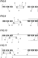
- the rear axle (5) is slaved so that it approaches closer to the platform (2) until the rear distance sensor (16) has detected the platform (2) ( Figures 4 and 5 ).
- the angular ratio R dockingSimpl is preferably between 0 and 10. Its default value is equal to 2, but it can be adjusted empirically by real-world tests for each type of vehicle.
- the rear axle (5) When the rear distance sensor (16) detects the platform (2), the rear axle (5) is driven in docking mode and the rear wheels (9) are steered so that the rear axle (5) reaches the maximum near the wharf (2) without colliding with it ( figure 6 ). This operation can cause the vehicle (3) to move crab.
- the steering of the rear wheels (9) is adapted according to the distance D ARquai of the rear of the vehicle (3) with respect to the platform (2), so that the wheels (9, 11) of the vehicle (3) do not collide with the platform (2).
- D ARquai is a polynomial law of degree 2 of type: at quaiAR * x 2 + b quaiAR * x + vs quaiAR
- the factors of the above formula can be empirically adjusted by real-life tests for each type of vehicle (3) taking into account the specificities of the type of place where it performs its docking maneuvers.
- the driver drives his vehicle (3) at a reduced speed and the assistance device (1) according to the invention is switched to docking mode.
- the wheels of the rear axle (5) remain driven in road mode as long as the front distance sensor (15) has not detected the platform (2) ( figure 5 ).
- This operation can cause the vehicle (3) to move crab if the environment allows it, or to move more conventionally in case of obstacle to avoid.
- f (D ARenv ) is a polynomial law of degree 2 of type: at ca. * x 2 + b ca. * x + vs ca.
- D ARquai is a polynomial law of degree 2 of type: at quaiAR * x 2 + b quaiAR * x + vs quaiAR
- D AVquai is a polynomial law of degree 1 of type: at quaiAV * D AVquai - D arched + b quaiAV
- the driver authorizes the opening of the doors.
- the rear wheels (9) are preferably controlled so as to be straight so as to be located closer to the platform (2), but this can increase the wear of the tires, also this orientation right rear wheels (9) can be optional.
- the vehicle (3) is located closer to the platform (2), both at the front and at the rear, so as to facilitate the ascent and descent of the passengers ( figure 7 ).
- the vehicle (3) can leave the dock (2).
- the rear axle (5) remains locked with the rear wheels (9) preferably in the upright position as the doors are not locked.
- the assistance device (1) according to the invention is then switched to docking mode.
- the assistance device (1) of the invention prohibits the rear axle (5) to steer the rear wheels (9) towards the dock (2).
- k start is chosen with a value equal to 20%. As before, this value can be refined empirically.
- the rear wheels (9) are not steered proportionally to the steering control received by the wheels (11) of the front axle (4), but steered according to a fixed steering angle, for example equal to 5 ° to the left.
- the rear wheels (9) are turned in the same way as during the approach phase but in a reverse manner.
- the rear axle (5) leaves the platform (2) as quickly as possible without ever colliding with its environment and without moving away from the platform (2) faster than the front axle (6).
- the tilting of the assistance device (1) of the invention in road mode can be done manually by the driver by means of the docking / road mode switch (20). ), automatically when the vehicle speed (3) is greater than the maximum speed for docking V MAXoading (default is 10 km / h) or automatically when the steering angle A AV on the right of the front wheels (11 ) is greater than an angle ⁇ ExitMessage exit steering port .
- the angle ⁇ ExitMessage exit steering bend can be expressed as an absolute angle or as a percentage of the angle A AV-max of maximum steering of the front wheels (11). This ⁇ - exit angle is preferably equal to 5 ° to the right, this value being able to be refined empirically.
- the assistance device (1) for docking maneuvers at a platform (2) according to the first variant of the invention is also intended to be used during a reverse gear of the vehicle (3) which is equipped, for all driving modes of the rear axle (5).
- the assistance device (1) In the driving phase, the assistance device (1) is in road mode and no modification of the driving law is necessary.
- the piloting law is not modified.
- the piloting law is reversed, that is to say that the rear wheels (9) are driven so as to approach the dock, without never collide with it.
- the assistance device (1) for docking maneuvers at a platform (2) according to the second variant of the invention is also provided during a reverse gear of the vehicle (3) which is equipped with it, for all the driving modes of the rear axle (5).
- the assistance device (1) In the driving phase, the assistance device (1) is in road mode and no modification of the driving law is necessary.
Landscapes
- Engineering & Computer Science (AREA)
- Mechanical Engineering (AREA)
- Chemical & Material Sciences (AREA)
- Combustion & Propulsion (AREA)
- Transportation (AREA)
- Mathematical Physics (AREA)
- Physics & Mathematics (AREA)
- Theoretical Computer Science (AREA)
- Human Computer Interaction (AREA)
- Steering Control In Accordance With Driving Conditions (AREA)
- Steering-Linkage Mechanisms And Four-Wheel Steering (AREA)
- Electric Propulsion And Braking For Vehicles (AREA)
- Power Steering Mechanism (AREA)
Description
La présente invention se rapporte à véhicule routier comportant un dispositif d'assistance pour les manoeuvres d'accostage au niveau d'un quai.The present invention relates to a road vehicle comprising an assistance device for docking maneuvers at a platform.
L'invention concerne tout type de véhicule à essieux articulés, plus particulièrement un véhicule routier de transport en commun de type bus, comportant un dispositif qui assiste le chauffeur lors des manoeuvres d'approche et de départ d'un quai de sorte que le véhicule n'entre pas en collision avec son environnement et qu'il soit au plus près du quai en fin de manoeuvre d'approche.The invention relates to any type of articulated axle vehicle, more particularly a bus-type public transport road vehicle, comprising a device that assists the driver during approach and departure maneuvers of a platform so that the vehicle does not collide with its surroundings and is closer to the wharf at the end of the approach maneuver.
Il est connu, notamment dans le domaine des véhicules routiers de transport spéciaux, par exemple dans le domaine des grumiers, d'équiper les véhicules avec des essieux directeurs pouvant être commandés par le chauffeur lors des manoeuvres difficiles. Ce type de dispositif est habituellement commandé par une télécommande, avec le chauffeur quittant son poste de conduite pour commander les différents déplacements des essieux depuis l'extérieur du véhicule.It is known, particularly in the field of special road transport vehicles, for example in the field of logging trucks, to equip vehicles with steering axles that can be controlled by the driver during difficult maneuvers. This type of device is usually controlled by a remote control, with the driver leaving his driving position to control the various movements of the axles from outside the vehicle.
Ce type de dispositif n'est donc pas adapté à la conduite en milieu urbain où il est notamment dangereux pour le chauffeur de quitter son poste de conduite.This type of device is not suitable for driving in urban areas where it is particularly dangerous for the driver to leave his driving position.
Il est également connu d'équiper les véhicules routiers avec diverses capteurs ou caméras permettant d'assister le chauffeur lors des manoeuvres difficiles en lui fournissant de nombreuses informations visuelles ou sonores concernant notamment la présence, la position et la distance des obstacles situés autour de son véhicule.It is also known to equip road vehicles with various sensors or cameras to assist the driver during difficult maneuvers by providing him with many visual or sound information including the presence, position and distance of obstacles around his driver. vehicle.
Parfois, ces capteurs ou caméras sont associés à une intelligence électronique pour commander l'essieu avant du véhicule de manière automatique.Sometimes these sensors or cameras are associated with electronic intelligence to control the front axle of the vehicle automatically.
Ainsi, il existe des dispositifs anticollision et des dispositifs de correction de trajectoire qui agissent sur la direction avant du véhicule à grande vitesse afin d'éviter des accidents.Thus, there are anti-collision devices and trajectory correction devices that act on the forward direction of the vehicle at high speed to avoid accidents.
On connait également des dispositifs anticollision et des dispositifs de correction de trajectoire pour des véhicules dont les roues de l'essieu arrière peuvent être légèrement braquées, selon un angle de braquage dont la valeur absolue est habituellement inférieure à 2°. Cet angle de braquage très limité ne permet pas d'assister le chauffeur pour les manoeuvres d'accostage à faible vitesse.Anti-collision devices and trajectory correction devices are also known for vehicles whose wheels are the rear axle can be slightly steered, according to a steering angle whose absolute value is usually less than 2 °. This very limited steering angle does not help the driver for low speed berthing maneuvers.
Il n'existe cependant pas de capteurs associés à une intelligence électronique pour commander de manière automatique un essieu arrière directeur d'un véhicule routier en vue d'assister le chauffeur pour les manoeuvres à faible vitesse, notamment les manoeuvres d'accostage au niveau d'un quai.There are, however, no sensors associated with electronic intelligence to automatically control a steering rear axle of a road vehicle to assist the driver in low speed maneuvers, including docking maneuvers at the highway. 'a dock.
En effet les manoeuvres d'accostage au niveau d'un quai avec un véhicule routier de transport en commun sont souvent difficiles en milieu urbain. En raison de la présence de piétons susceptibles de marcher sur les emplacements réservés au bus, de voitures mal garées qui empiètent parfois sur ces emplacements au niveau des arrêts de bus, ou d'obstacles urbains divers, il est parfois difficile pour le chauffeur d'effectuer des manoeuvres d'approche et de départ d'un quai de sorte que le véhicule n'entre pas en collision avec son environnement et qu'il soit au plus près du quai en fin de manoeuvre d'approche.
L'objet de la présente invention vise par conséquent à pallier les inconvénients de l'art antérieur en proposant un nouveau véhicule routier comportant un dispositif d'assistance pour les manoeuvres d'accostage au niveau d'un quai.The object of the present invention is therefore to overcome the disadvantages of the prior art by proposing a new road vehicle comprising an assistance device for docking maneuvers at a dock.
Ce dispositif d'assistance est d'un fonctionnement automatique lorsqu'il est enclenché. Ainsi, lors des manoeuvres d'accostage au niveau d'un quai, le chauffeur ne se préoccupe pas du dispositif d'assistance une fois celui-ci activé. Le chauffeur conduit son véhicule de manière classique, en orientant l'essieu directeur avant de manière classique avec son volant, tandis que le dispositif d'assistance de l'invention s'occupe d'orienter un essieu arrière qui est modifié de manière à être directeur, sans que le chauffeur ait à s'en soucier.This assistance device is of automatic operation when it is switched on. Thus, when docking maneuvers at a dock, the driver does not worry about the assistance device once it activated. The driver drives his vehicle in a conventional manner, by orienting the front steering axle in a conventional manner with his steering wheel, while the assistance device of the invention is concerned with orienting a rear axle which is modified so as to be director, without the driver having to worry about it.
Selon cette invention, les roues de l'essieu arrière peuvent être braquées selon un angle dont la valeur absolue est bien supérieure à 2°, par exemple supérieure à 10°, préférentiellement supérieure à 20° et encore plus préférentiellement supérieure à 30°.According to this invention, the wheels of the rear axle can be steered at an angle whose absolute value is much greater than 2 °, for example greater than 10 °, preferably greater than 20 ° and even more preferably greater than 30 °.
Le fait qu'un essieu arrière soit directeur permet au véhicule routier d'effectuer des manoeuvres d'accostage sur une plus courte distance, ce qui est particulièrement avantageux lorsque les emplacements réservés au niveau des arrêts de bus pour les véhicules de transport en commun sont de taille réduite.The fact that a rear axle is steering allows the road vehicle to make docking maneuvers for a shorter distance, This is particularly advantageous when the reserved spaces at the bus stops for the public transport vehicles are small.
Cela permet également d'approcher l'arrière du véhicule au plus près du quai lors des manoeuvres d'approche de sorte que le véhicule soit à la fois au plus près du quai et bien parallèle à celui-ci. Ceci est particulièrement important dans le domaine des véhicules de transport en commun susceptibles de transporter des passagers en chaise roulante, avec des poussettes ou des paniers à roulettes.It also allows approaching the rear of the vehicle closer to the dock during approaching maneuvers so that the vehicle is both closer to the dock and parallel to it. This is particularly important in the field of public transport vehicles that can carry passengers in wheelchairs, with strollers or roller baskets.
Un autre objet de la présente invention vise à proposer un nouveau procédé d'accostage au niveau d'un quai pour un véhicule routier équipé du dispositif d'assistance de l'invention.Another object of the present invention is to provide a new method of docking at a dock for a road vehicle equipped with the assistance device of the invention.
Selon l'invention, les objets assignés à l'invention sont atteints à l'aide d'un véhicule routier comportant des roues avant montées sur un essieu avant directeur et des roues arrière montées sur un essieu arrière, caractérisé en ce qu'il comporte un dispositif d'assistance pour les manoeuvres d'accostage au niveau d'un quai et en ce que l'essieu arrière est directeur et équipé d'une direction, le dispositif d'assistance étant prévu pour fonctionner selon un mode routier ou selon un mode accostage et comprenant les moyens suivants :
- un dispositif de pilotage en direction prévu pour commander l'angle de braquage AAR des roues arrière ;
- un capteur de distance prévu à l'arrière du véhicule pour mesurer la distance DARquai de l'arrière du véhicule par rapport au quai ;
- en mode routier, soit les roues arrière sont droites, soit leur angle de braquage AAR est commandé par le dispositif de pilotage en direction en fonction de l'angle de braquage AAV des roues avant ;
- en mode accostage, l'angle de braquage des roues arrière est commandé par le dispositif de pilotage en direction en fonction des distances mesurées par le capteur de distance et de l'angle des roues avant AAV.
- a steering device provided for controlling the steering angle A AR of the rear wheels;
- a distance sensor provided at the rear of the vehicle for measuring the distance D ARquai from the rear of the vehicle relative to the wharf;
- in road mode, either the rear wheels are straight, or their steering angle A AR is controlled by the steering device in direction according to the steering angle A AV of the front wheels;
- in docking mode, the steering angle of the rear wheels is controlled by the steering device in direction according to the distances measured by the distance sensor and the angle of the front wheels A AV .
Ainsi, le dispositif d'assistance pilote le braquage des roues arrière de manière entièrement automatique, de manière à optimiser et faciliter les différentes manoeuvres effectuées par le chauffeur lors d'un accostage à un quai.Thus, the assistance device controls the steering of the rear wheels fully automatically, so as to optimize and facilitate the various maneuvers performed by the driver when docking at a dock.
Selon une variante de l'invention, le dispositif d'assistance comprend en outre les moyens suivants :
- un capteur de distance prévu à l'avant pour mesurer la distance DAVquai de l'avant du véhicule par rapport au quai ;
- un capteur de distance prévu à l'arrière du véhicule pour mesurer la distance DARenv de l'arrière du véhicule par rapport aux autres obstacles de l'environnement ;
- en mode routier, soit les roues arrière sont droites, soit leur angle de braquage AAR est commandé par le dispositif de pilotage en direction en fonction de l'angle de braquage AAV des roues avant ;
- en mode accostage, l'angle de braquage des roues arrière est commandé par le dispositif de pilotage en direction en fonction des distances mesurées par les capteurs de distance et en fonction de l'angle de braquage AAV des roues avant.
- a distance sensor provided at the front for measuring the distance D AVquai from the front of the vehicle relative to the wharf;
- a distance sensor provided at the rear of the vehicle for measuring the distance D ARenv from the rear of the vehicle relative to other obstacles in the environment;
- in road mode, either the rear wheels are straight, or their steering angle A AR is controlled by the steering device in direction according to the steering angle A AV of the front wheels;
- in docking mode, the steering angle of the rear wheels is controlled by the steering device in direction according to the distances measured by the distance sensors and according to the steering angle A AV of the front wheels.
Ainsi, grâce à des capteurs de distance supplémentaires, le dispositif d'assistance pilote le braquage des roues arrière de manière encore plus optimisée pour faciliter les différentes manoeuvres effectuées par le chauffeur lors d'un accostage à un quai.Thus, thanks to additional distance sensors, the assistance device controls the turning of the rear wheels even more optimized to facilitate the various maneuvers performed by the driver when docking at a dock.
Selon un exemple de mise en oeuvre de l'invention, le dispositif d'assistance comprend en outre un capteur de distance prévu à l'avant du véhicule pour mesurer la distance DAVenv de l'avant du véhicule par rapport aux autres obstacles de l'environnement.According to an exemplary implementation of the invention, the assistance device further comprises a distance sensor provided at the front of the vehicle for measuring the distance D AVenv from the front of the vehicle relative to the other obstacles of the vehicle. 'environment.
Selon un autre exemple de mise en oeuvre de l'invention, les roues arrière peuvent être braquées selon un angle dont la valeur absolue est supérieure à 10°, préférentiellement supérieure à 20° et plus préférentiellement supérieure à 30°. Cet angle de braquage, très supérieur à celui des essieux directeurs arrière existant, permet d'optimiser les différentes manoeuvres d'accostage par rapport aux véhicules de l'art antérieur.According to another example of implementation of the invention, the rear wheels can be steered at an angle whose absolute value is greater than 10 °, preferably greater than 20 ° and more preferably greater than 30 °. This steering angle, much higher than that of existing rear axle steering, optimizes the different docking maneuvers compared to vehicles of the prior art.
Selon un exemple de mise en oeuvre de l'invention, en mode routier, le dispositif de pilotage en direction commande l'angle de braquage AAR des roues arrière de sorte que les roues arrière sont d'abord droites puis, au-delà d'un certain angle de braquage des roues avant, les roues arrière sont asservies en braquage de manière proportionnelle et linéaire par rapport à la commande de braquage reçue par les roues avant.According to an exemplary implementation of the invention, in road mode, the steering control device controls the steering angle A AR of the rear wheels so that the rear wheels are at first straight and then, beyond a certain steering angle of the front wheels, the rear wheels are slaved in a proportional and linear manner with respect to the steering control received by the front wheels.
Selon un exemple supplémentaire de mise en oeuvre de l'invention, en mode routier l'essieu arrière est fixe avec les roues arrière droites lorsque la vitesse du véhicule est supérieure à la vitesse maximale du mode routier SVAR. Ceci permet d'éviter tout risque de comportement dangereux du véhicule lorsque celui-ci roule à une certaine vitesse.According to a further example of implementation of the invention, in road mode the rear axle is fixed with the rear wheels right when the vehicle speed is greater than the maximum speed of the road mode S VAR . This avoids any risk of dangerous behavior of the vehicle when it runs at a certain speed.
Selon un exemple de mise en oeuvre de l'invention, le dispositif d'assistance bascule automatiquement du mode accostage vers le mode routier lorsque la vitesse du véhicule est supérieure à une vitesse maximale pour l'accostage VMAXaccostage ou lorsque l'angle de braquage AAV des roues avant est supérieur à un angle αSortieAccostage de braquage de sortie d'accostage. Ceci permet notamment d'éviter tout risque de comportement dangereux du véhicule lorsque celui-ci roule à une certaine vitesse.According to an exemplary implementation of the invention, the assistance device switches automatically from the docking mode to the road mode when the vehicle speed is greater than a maximum speed for docking V MAXaccostage or when the steering angle AT front wheels is greater than an angle α ExitMailing exit steering lock . This allows in particular to avoid any risk of dangerous behavior of the vehicle when it runs at a certain speed.
Selon un exemple autre de mise en oeuvre de l'invention le dispositif d'assistance comprend des capteurs permettant de mesurer l'angle de braquage AAV des roues avant et l'angle de braquage AAR des roues arrière. Ces capteurs permettent de donner des informations nécessaires au fonctionnement du dispositif d'assistance, notamment en mode routier.According to another example of implementation of the invention the assistance device comprises sensors for measuring the steering angle A AV of the front wheels and the steering angle A AR of the rear wheels. These sensors provide information necessary for the operation of the assistance device, especially in road mode.
Selon cet exemple de mise en oeuvre de l'invention, lorsque l'essieu avant comporte un boitier de direction, et en ce que l'angle de braquage AAV des roues avant peut être mesuré par un capteur d'angle qui est relié à ce boitier de direction.According to this example of implementation of the invention, when the front axle comprises a steering box, and in that the steering angle A AV of the front wheels can be measured by an angle sensor which is connected to this steering box.
De même, lorsque le dispositif de pilotage en direction comprend un actionneur à tige mobile, l'angle de braquage AAR des roues arrière peut être mesuré par un capteur de position relié à l'actionneur du dispositif de pilotage en direction, l'angle de braquage AAR des roues arrière étant calculé en fonction de la position de la tige de l'actionneur.Similarly, when the steering control device comprises a movable rod actuator, the steering angle A AR of the rear wheels can be measured by a position sensor connected to the actuator of the steering device in the direction, the angle steering A AR rear wheels being calculated according to the position of the rod of the actuator.
Selon un exemple de mise en oeuvre de l'invention, les capteurs de distance sont prévus sur le côté droit du véhicule, notamment dans le cas où le véhicule est prévu pour circuler à droite.According to an exemplary implementation of the invention, the distance sensors are provided on the right side of the vehicle, particularly in the case where the vehicle is intended to circulate on the right.
Selon un autre exemple de mise en oeuvre de l'invention, les capteurs de distance prévus à l'avant du véhicule sont prévus devant les roues avant, le capteur de distance au quai prévu à l'arrière du véhicule est prévu devant les roues arrière, et le capteur d'environnement arrière est prévu à l'arrière des roues arrière. Ceci permet aux capteurs d'être situés au plus près des obstacles qu'ils doivent détecter.According to another exemplary embodiment of the invention, the distance sensors provided at the front of the vehicle are provided in front of the front wheels, the distance sensor at the platform provided at the rear of the vehicle is provided in front of the rear wheels. , and the rear environmental sensor is provided at the rear of the rear wheels. This allows the sensors to be located closer to the obstacles they must detect.
Selon un exemple supplémentaire de mise en oeuvre. de l'invention, les informations de distance à l'avant et à l'arrière qui sont reçues par les capteurs de distance sont transmises au chauffeur de manière visuelle, ce qui l'aide dans sa conduite.According to an additional example of implementation. of the invention, the distance information at the front and rear which are received by the distance sensors are transmitted to the driver visually, which helps him in his driving.
Selon un exemple de mise en oeuvre de l'invention, le dispositif
d'assistance comprend un commutateur de mode accostage/routier qui fait basculer le dispositif d'assistance du mode routier en mode accostage et inversement lorsqu'il est actionné.According to an exemplary implementation of the invention, the device
of assistance includes a docking / road mode switch which switches the assistance device from the road mode to the docking mode and vice versa when it is activated.
Selon cet exemple de mise en oeuvre de l'invention, le commutateur de mode accostage/routier peut être actionné manuellement par le chauffeur au moyen d'un bouton prévu dans le poste de conduite du véhicule.According to this embodiment of the invention, the docking mode / road mode switch can be actuated manually by the driver by means of a button provided in the driving position of the vehicle.
Le commutateur de mode accostage/routier peut également être actionné par un dialogue sans contact entre l'infrastructure et le véhicule. Ainsi le chauffeur n'a pas besoin de se préoccuper d'actionner le commutateur de mode accostage/routier, cela se fait automatiquement par exemple lorsque le véhicule s'approche ou s'éloigne d'un quai équipé d'un dispositif de dialogue sans contact avec le véhicule.The berthing / road mode switch can also be operated by a contactless dialogue between the infrastructure and the vehicle. Thus the driver does not need to worry about operating the mode switch docking / road, this is done automatically for example when the vehicle approaches or away from a dock equipped with a dialogue device without contact with the vehicle.
Selon un exemple de mise en oeuvre de l'invention, le commutateur de mode accostage/routier ne permet pas de faire basculer le dispositif d'assistance du mode routier en mode accostage tant que le véhicule roule à une vitesse supérieure à la vitesse maximale pour l'accostage VMAXaccostage. Ceci permet d'éviter tout risque de comportement dangereux du véhicule lorsque celui-ci roule à une certaine vitesse.According to an exemplary implementation of the invention, the docking mode / road mode switch does not make it possible to switch the assistance device from the road mode to the docking mode as long as the vehicle is traveling at a speed greater than the maximum speed for the docking V MAXaccostage . This avoids any risk of dangerous behavior of the vehicle when it runs at a certain speed.
Selon un exemple de mise en oeuvre de l'invention, le dispositif d'assistance comprend également une intelligence embarquée qui pilote le dispositif de pilotage en direction de l'essieu arrière.According to an exemplary implementation of the invention, the assistance device also comprises an onboard intelligence that drives the steering device towards the rear axle.
Cette intelligence embarquée est par exemple connectée aux capteurs de distance, aux capteurs permettant de mesurer l'angle de braquage AAV des roues avant et l'angle de braquage AAR des roues arrière, et au commutateur de mode accostage/routier.This embedded intelligence is for example connected to the distance sensors, the sensors for measuring the steering angle A AV of the front wheels and the steering angle A AR of the rear wheels, and the docking / road mode switch.
L'intelligence embarquée peut comporter une mémoire dans laquelle sont stockées les formules mathématiques utilisées par le dispositif d'assistance pour commander l'angle de braquage des roues arrière en mode routier et en mode accostage, ainsi que les valeurs des constantes utilisées dans ces formules.The embedded intelligence may include a memory in which are stored the mathematical formulas used by the assistance device to control the steering angle of the rear wheels in road mode and in docking mode, as well as the values of the constants used in these formulas. .
Les objets assignés à l'invention sont atteints également à l'aide d'un procédé d'accostage à un quai pour un véhicule routier tel que décrit précédemment, caractérisé en ce qu'il comprend les étapes successives suivantes :
- a) une phase de roulage, lorsque le véhicule circule de manière classique, dans laquelle le dispositif d'assistance est basculé en mode routier et dans laquelle les roues arrière sont droites ou asservies à la direction avant ;
- b) une phase d'approche, lorsque le véhicule débute son accostage à un quai, dans laquelle le dispositif d'assistance est basculé en mode accostage, dans laquelle les roues arrière restent en mode routier tant que le détecteur de distance avant n'a pas détecté le quai, et dans laquelle, lorsque le détecteur de distance avant détecte le quai, les roues arrière sont pilotées par le dispositif d'assistance et braquées de sorte que l'essieu arrière soit déplacé en direction du quai ;
- c) une phase d'arrêt, lorsque le véhicule est accosté à quai ;
- d) une phase de départ, lorsque le véhicule quitte le quai, dans laquelle le dispositif d'assistance est basculé en mode accostage et dans laquelle les roues arrière sont braquées de sorte que l'essieu arrière soit déplacé en éloignement du quai ;
- e) une phase de roulage, lorsque le véhicule circule de manière classique après avoir terminé de quitter le quai, dans laquelle le dispositif d'assistance est basculé en mode routier et dans laquelle les roues arrière sont droites ou asservies à la direction avant.
- a) a driving phase, when the vehicle is traveling in a conventional manner, in which the assistance device is switched to road mode and in which the rear wheels are straight or slaved to the forward direction;
- (b) an approach phase, when the vehicle begins docking at a platform, in which the assistance device is switched to docking mode, in which the rear wheels remain in road mode until the forward distance sensor has not sensing the dock, and wherein, when the forward distance sensor detects the dock, the rear wheels are driven by the assist device and steered so that the rear axle is moved toward the dock;
- (c) a stopping phase, when the vehicle is docked;
- d) a departure phase, when the vehicle leaves the platform, in which the assistance device is switched to docking mode and in which the rear wheels are steered so that the rear axle is moved away from the dock;
- e) a driving phase, when the vehicle is traveling in a conventional manner after having left the platform, in which the assistance device is switched to road mode and in which the rear wheels are straight or slaved to the forward direction.
Selon ce procédé d'accostage, au cours de la phase d'arrêt, lorsque le véhicule est accosté à quai, les roues arrière peuvent être pilotées de manière à être ramenées en position non braquées. En effet, cela permet au véhicule d'être au plus près du quai, et des roues braquées peuvent parfois gêner l'ouverture des portes latérales dudit véhicule.According to this docking method, during the stopping phase, when the vehicle is docked, the rear wheels can be driven so as to be returned to the non-steered position. Indeed, this allows the vehicle to be closer to the dock, and steered wheels can sometimes interfere with the opening of the side doors of said vehicle.
Ce procédé facilite considérablement les manoeuvres d'accostage pour le chauffeur. Cet accostage est ainsi optimisé de manière automatique par le dispositif d'assistance, permettant notamment au véhicule d'accoster de manière parallèle et proche d'un quai de manière bien plus aisée, sécuritaire et sur une distance bien plus courte qu'avec les véhicules classiques.This process greatly facilitates docking maneuvers for the driver. This docking is thus optimized automatically by the assistance device, allowing the vehicle to dock in a parallel manner and close to a dock much easier, safer and a much shorter distance than with vehicles classics.
Grâce à l'invention, la lacune est réduite entre le véhicule et le quai pour un accès facilité au véhicule. La distance au quai étant maîtrisée, les flancs des roues ne viennent plus frotter contre le quai, ce qui empêche leur usure prématurée.Thanks to the invention, the gap is reduced between the vehicle and the platform for easy access to the vehicle. The distance to the dock being controlled, the sides of the wheels do not come rubbing against the dock, which prevents their premature wear.
De même, la longueur nécessaire pour la réalisation de l'accostage est réduite, ce qui permet au véhicule d'accoster même lorsque la place disponible serait trop faible pour un véhicule classique.Likewise, the length necessary to achieve the docking is reduced, which allows the vehicle to dock even when the available space would be too low for a conventional vehicle.
Par l'optimisation du temps et du nombre de manoeuvres nécessaire pour un accostage, l'invention permet également d'optimiser la consommation en carburant du véhicule.By optimizing the time and the number of maneuvers necessary for a docking, the invention also makes it possible to optimize the fuel consumption of the vehicle.
Enfin, les capteurs de l'invention permettent une assistance visuelle à la conduite qui est indépendante de la météo et de la visibilité.Finally, the sensors of the invention allow a visual assistance to driving that is independent of the weather and visibility.
D'autres caractéristiques et avantages de la présente invention apparaîtront plus clairement à la lecture de la description qui va suivre, faite en référence aux dessins annexés, donnés à titre d'exemples non limitatifs, dans lesquels :
- la
figure 1 est un graphique illustrant la loi mathématique donnant l'angle de braquage des roues arrière par rapport à l'angle de braquage des roues avant lorsque l'essieu arrière fonctionne en mode routier ; - la
figure 2 est une vue schématique illustrant un véhicule routier équipé d'un dispositif d'assistance pour les manoeuvres d'accostage au niveau d'un quai selon une première variante de l'invention ; - la
figure 3 est une vue schématique illustrant un véhicule routier équipé d'un dispositif d'assistance pour les manoeuvres d'accostage au niveau d'un quai selon une seconde variante de l'invention ; et - les
figures 4 à 11 sont des vues schématiques illustrant les manoeuvres d'approche et de départ d'un quai pour un véhicule routier équipé d'un dispositif d'assistance selon l'invention, sur lesquelles la trajectoire de l'essieu avant est représentée en pointillés.
- the
figure 1 is a graph illustrating the mathematical law giving the steering angle of the rear wheels in relation to the steering angle of the front wheels when the rear axle operates in road mode; - the
figure 2 is a schematic view illustrating a road vehicle equipped with an assistance device for queuing maneuvers at a platform according to a first variant of the invention; - the
figure 3 is a schematic view illustrating a road vehicle equipped with an assistance device for queuing maneuvers at a platform according to a second variant of the invention; and - the
Figures 4 to 11 are schematic views illustrating the approach and departure maneuvers of a platform for a road vehicle equipped with an assistance device according to the invention, on which the trajectory of the front axle is shown in dotted lines.
Les éléments structurellement et fonctionnellement identiques présents sur plusieurs figures distinctes, sont affectés d'une même référence numérique ou alphanumérique.The structurally and functionally identical elements present in several separate figures are assigned a same numerical or alphanumeric reference.
Le dispositif d'assistance (1) pour les manoeuvres d'accostage au niveau d'un quai (2) selon l'invention est prévu pour un véhicule routier (3) comportant un essieu avant directeur (4) équipé d'une direction (6) classique actionnée par le volant du véhicule (3). La direction avant (6) est par exemple assistée par un boîtier de direction à assistance hydraulique à assistance variable (non représenté).The assistance device (1) for the docking maneuvers at a platform (2) according to the invention is provided for a road vehicle (3) comprising a steering front axle (4) equipped with a steering wheel ( 6) conventional actuated by the steering wheel of the vehicle (3). The forward direction (6) is for example assisted by a variable power assisted hydraulic steering box (not shown).
Dans la suite de ce descriptif, pour des raisons de commodité, nous avons utilisé le terme "quai" afin de désigner tout type de bordure, d'emmarchement d'accès au véhicule ou tout autre moyen physique, fixe, ou mobile par rapport au sol, sur lequel les voyageurs se tiennent debout avant d'embarquer dans un véhicule. Aussi, le terme "quai" ne devra pas être interprété de manière limitative, mais comme se rapportant à tout type similaire de bordure.In the remainder of this description, for reasons of convenience, we have used the term "platform" to designate any type of border, access to the vehicle or any other physical, fixed, or mobile means in relation to the ground, on which travelers stand before boarding a vehicle. Also, the term "wharf" should not be interpreted in a limiting manner, but as referring to any similar type of border.
Le dispositif d'assistance (1) de l'invention est préférentiellement prévu pour un véhicule routier (3) de transport en commun, par exemple un bus, mais il peut être adapté à tout type de véhicule routier (3).The assistance device (1) of the invention is preferably provided for a road transport vehicle (3), for example a bus, but it can be adapted to any type of road vehicle (3).
Le dispositif d'assistance (1) selon l'invention est également prévu pour faire fonctionner l'essieu arrière (5) d'un véhicule routier (3) selon deux modes, à savoir un mode routier et un mode accostage. Selon l'invention, l'essieu arrière (5) est aussi directeur et équipé d'une direction (7), mais il n'est pas commandé par le chauffeur du véhicule routier (3). En effet, la direction arrière (7) est entièrement pilotée de manière automatique par le dispositif d'assistance (1) selon l'invention.The assistance device (1) according to the invention is also intended to operate the rear axle (5) of a road vehicle (3) in two modes, namely a road mode and a docking mode. According to the invention, the rear axle (5) is also steering and equipped with a steering (7), but it is not controlled by the driver of the road vehicle (3). Indeed, the rear direction (7) is fully automatically controlled by the assistance device (1) according to the invention.
Afin de piloter l'angle de braquage des roues arrière (9) dans ses deux modes de fonctionnement, le dispositif d'assistance (1) selon l'invention comprend un dispositif de pilotage en direction (10) de l'essieu arrière (5). Ce dispositif de pilotage en direction (10) comprend un actionneur, préférentiellement sous la forme d'un vérin hydraulique associé à un distributeur proportionnel, ou sous la forme d'un vérin électrique.In order to control the steering angle of the rear wheels (9) in its two modes of operation, the assistance device (1) according to the invention comprises a steering device in the direction (10) of the rear axle (5). ). This steering device in direction (10) comprises an actuator, preferably in the form of a hydraulic cylinder associated with a proportional distributor, or in the form of an electric cylinder.
De manière générale, en mode routier, les roues arrière (9) sont d'abord droites puis, au-delà d'un certain angle de braquage des roues avant (11), les roues arrière (9) sont asservies en braquage de manière proportionnelle par rapport à la commande de braquage reçue par les roues avant (11).Generally speaking, in road mode, the rear wheels (9) are at first straight and then, beyond a certain steering angle of the front wheels (11), the rear wheels (9) are slaved in a controlled manner. proportional to the steering control received by the front wheels (11).
Selon une variante moins avantageuse de l'invention, en mode routier les roues arrière (9) sont toujours droites, à la manière d'un véhicule classique.According to a less advantageous variant of the invention, in road mode the rear wheels (9) are always straight, in the manner of a conventional vehicle.
Par roues droites, on entend des roues qui ne sont pas braquées, c'est-à-dire avec un angle de braquage de 0° correspondant à des roues alignées dans le sens longitudinal du véhicule.By straight wheels is meant wheels that are not steered, that is to say with a steering angle of 0 ° corresponding to wheels aligned in the longitudinal direction of the vehicle.
En mode accostage, l'angle de braquage des roues arrière (9) est commandé par le dispositif d'assistance (1) en fonction des distances du véhicule (3) par rapport au quai (2) et aux autres obstacles de l'environnement.In docking mode, the steering angle of the rear wheels (9) is controlled by the assistance device (1) as a function of the distances of the vehicle (3) in relation to the wharf (2) and other environmental obstacles.
Les deux modes de fonctionnement du dispositif d'assistance (1) de l'invention vont maintenant être décrits de manière plus détaillée.The two modes of operation of the assistance device (1) of the invention will now be described in more detail.
En mode routier, l'essieu arrière (5) est prévu pour le roulage normal du véhicule (3) sur la chaussée (8), selon une vitesse maximale respectueuse des limitations de vitesse du code de la route. Dans ce mode, les roues arrière (9) sont asservies à la position des roues avant (11) par une loi mathématique tenant compte de l'angle de braquage des roues avant (11). Cette loi mathématique régissant le mode routier est représentée sur la
En mode routier, le véhicule (3) peut circuler à une vitesse dont la grandeur est incompatible avec les manoeuvres nécessaires lors de l'accostage à un quai (2). Par exemple, bien que cela puis être autorisé par le code de la route, il n'est pas envisageable pour un véhicule (3) d'accoster à un quai à une vitesse de 50 km/h.In road mode, the vehicle (3) can travel at a speed the size of which is incompatible with the maneuvers required when docking at a platform (2). For example, although it may be authorized by the Highway Code, it is not possible for a vehicle (3) to dock at a platform at a speed of 50 km / h.
En mode routier, les roues arrière (9) sont droites jusqu'à ce que les roues avant (11) soient braquées dans un sens ou dans l'autre au-delà d'un certain angle, désigné en tant que seuil de déblocage SAR-debloc, à partir duquel les roues arrière (9) sont braquées automatiquement par le dispositif d'assistance (1) de l'invention selon un angle de braquage proportionnel à celui des roues avant (11).In road mode, the rear wheels (9) are straight until the front wheels (11) are pointed in one direction or the other beyond a certain angle, designated as the unlocking threshold S AR-unblock , from which the rear wheels (9) are automatically steered by the assistance device (1) of the invention at a steering angle proportional to that of the front wheels (11).
Ainsi, comme cela est représenté sur la
Selon un mode de réalisation préféré de l'invention, l'asservissement des roues arrière (9) aux roues avant est effectué de manière progressive, ce qui se traduit par une courbe au niveau de la transition entre la position droite des roues arrière (9) et leur position asservie en braquage. Cette transition est obtenue par une loi de type polynomial de degré 2.According to a preferred embodiment of the invention, the servo-control of the rear wheels (9) to the front wheels is progressively carried out, which results in a curve at the level of the transition between the right position of the rear wheels (9 ) and their enslaved position in steering. This transition is obtained by a polynomial law of
Les lois mathématiques régissant le mode routier sont données ci- dessous : ![]()
![]()
![]()
![]()
![]()
![]()
![]()
- AAV : angle de braquage des roues avant (11), exprimé en degrés
- AAV-max : angle de braquage maximal des roues avant (11), exprimé en degrés
- AAR : angle de braquage des roues arrière (9), exprimé en degrés
- AAR-max : angle de braquage maximal des roues arrière (9), exprimé en degrés
- ATr : plage d'angle pour la transition, exprimée en degrés,
- SAR-debloc : seuil de déblocage des roues arrière (9), exprimé en pourcentage.
- A AV : steering angle of the front wheels (11), expressed in degrees
- A AV-max : maximum steering angle of the front wheels (11), expressed in degrees
- A AR : steering angle of the rear wheels (9), expressed in degrees
- A AR-max : maximum steering angle of the rear wheels (9), expressed in degrees
- At Tr : angle range for the transition, expressed in degrees,
- S AR-unblock : threshold for unlocking the rear wheels (9), expressed as a percentage.
Dans le cadre de ce descriptif, on considère qu'un angle de braquage de 0 pour des roues correspond à des roues droites, alignées selon l'axe longitudinal du véhicule.In the context of this description, it is considered that a steering angle of 0 for wheels corresponds to straight wheels, aligned along the longitudinal axis of the vehicle.
L'angle de braquage maximal AAR-max des roues arrière (9) dépend de manière intrinsèque du véhicule (3) et de sa construction. Il est habituellement compris environ entre -35° et +35°.The maximum turning angle A AR-max of the rear wheels (9) is intrinsically dependent on the vehicle (3) and its construction. It is usually between about -35 ° and + 35 °.
L'angle de braquage AAV des roues avant (11) est préférentiellement mesuré par un capteur d'angle (12) qui est relié au boitier de direction (13) de l'essieu avant (4), tandis que l'angle de braquage AAR des roues arrière (9) est préférentiellement mesuré par un capteur de position (14) relié à l'actionneur du dispositif de pilotage en direction (10) pour en mesurer le déplacement linéaire. Au moyen d'un régulateur proportionnel intégral dérivé (PID) le capteur de position (14) calcule alors l'angle de braquage AAR des roues arrière (9) en fonction de la position de la tige de l'actionneur.The steering angle A AV of the front wheels (11) is preferably measured by an angle sensor (12) which is connected to the steering box (13) of the front axle (4), while the steering angle steering A AR rear wheels (9) is preferably measured by a position sensor (14) connected to the actuator of the steering device in the direction (10) to measure the linear displacement. By means of a derivative integral proportional regulator (PID) the position sensor (14) then calculates the steering angle A AR of the rear wheels (9) as a function of the position of the actuator rod.
Selon une variante de l'invention (non représentée), l'angle de braquage AAV des roues avant (11) est mesuré par un capteur d'angle qui est logé dans le pivot d'au moins une des roues avant (11), tandis que l'angle de braquage AAR des roues arrière (9) est mesuré par un capteur d'angle qui est logé dans le pivot d'au moins une des roues arrière (9).According to a variant of the invention (not shown), the steering angle A AV of the front wheels (11) is measured by an angle sensor which is housed in the pivot of at least one of the front wheels (11). , while the steering angle A AR of the rear wheels (9) is measured by an angle sensor which is housed in the pivot of at least one of the rear wheels (9).
La plage d'angle pour la transition ATr est comprise entre 0° et 40°. Par défaut, elle est de 6° mais peut être affiné de manière empirique par des essais en situation réelle pour chaque type de véhicule (3).The angle range for the transition A Tr is between 0 ° and 40 °. By default, it is 6 ° but can be refined empirically by real-world tests for each type of vehicle (3).
Le seuil de déblocage SAR-debloc des roues arrière (9) est choisi en fonction du degré de pilotage voulu pour l'essieu arrière (5). Plus ce seuil SAR-debloc est faible, plus le chauffeur peut avoir l'impression que l'arrière du véhicule (3) «balaye» de trop. Au contraire, plus ce seuil SAR-debloc est élevé, plus la sensation de conduite s'approche de celle d'un véhicule classique dépourvu de dispositif d'assistance (1) pour les manoeuvres d'accostage et plus le mouvement de volant est important. Le seuil de déblocage SAR-debloc des roues arrière (9) est préférentiellement choisi à 25%, mais peut par exemple être supérieur à 25%, la valeur définitive retenue pouvant être obtenue de manière empirique par des essais en situation réelle pour chaque type de véhicule (3).The release threshold S AR-unlocked rear wheels (9) is selected according to the degree of control desired for the rear axle (5). The lower this threshold S AR-deblock , the more the driver may feel that the rear of the vehicle (3) "sweeps" too much. On the contrary, the higher this threshold S AR-unlocked , the more the driving sensation approaches that of a conventional vehicle without assistance device (1) for the docking maneuvers and more the steering wheel movement is important. The release threshold S AR-unlocked rear wheels (9) is preferably chosen at 25%, but may for example be greater than 25%, the final value retained can be obtained empirically by real-world tests for each type of vehicle (3).
En mode routier, il est également possible d'asservir les roues arrière (9) par une loi mathématique modifiée tenant compte de la vitesse du véhicule (3).In road mode, it is also possible to slave the rear wheels (9) by a modified mathematical law taking into account the speed of the vehicle (3).
Selon cette loi mathématique modifiée, l'angle de braquage AAR des roues arrière (9) est multiplié par un coefficient kvit qui dépend de la vitesse du véhicule, selon les formules suivantes : ![]()
![]()
- AAR : angle de braquage des roues arrière (9), exprimé en degrés et calculé selon les lois mathématiques précédentes
- A'AR : angle de braquage des roues arrière (9), tenant compte de la vitesse, exprimé en degrés
- AAV : angle de braquage des roues avant (11), exprimé en degrés
- pv : pente de l'asservissement en vitesse, compris entre -1 et 0
- SVAR : vitesse maximale du mode routier, exprimé en km/h.
V : Vitesse du véhicule, exprimé en km/h
- A AR : steering angle of the rear wheels (9), expressed in degrees and calculated according to previous mathematical laws
- A ' AR : steering angle of the rear wheels (9), taking into account speed, expressed in degrees
- A AV : steering angle of the front wheels (11), expressed in degrees
- p v : slope of the servocontrol in speed, between -1 and 0
- S VAR : maximum speed of the road mode, expressed in km / h.
V: Vehicle speed, expressed in km / h
La vitesse maximale du mode routier SVAR représente la vitesse maximale au-delà de laquelle l'essieu arrière (5) est fixe avec les roues arrière (9) droites (0°) lorsque le dispositif d'assistance (1) est en mode routier. En effet, au-delà d'une certaine vitesse du véhicule (3), on considère qu'il serait dangereux que l'essieu arrière (5) soit directeur car cela pourrait provoquer une instabilité du véhicule (3) au niveau de l'arrière lorsque le chauffeur prend un virage. La vitesse maximale du mode routier SVAR est de 40 km/h par défaut en milieu urbain, mais peut être affinée de manière empirique par des essais en situation réelle pour chaque type de véhicule (3) en tenant compte des spécificités du parcours sur lequel il est prévu pour circuler.The maximum speed of the road mode S VAR represents the maximum speed beyond which the rear axle (5) is fixed with the right rear wheels (9) (0 °) when the assistance device (1) is in the operating mode. road. Indeed, beyond a certain speed of the vehicle (3), it is considered that it would be dangerous for the rear axle (5) to be steered as this could cause instability of the vehicle (3) at the level of the vehicle. back when the driver takes a turn. The maximum speed of the S VAR road mode is 40 km / h by default in urban areas, but can be empirically refined by real-life tests for each type of vehicle (3) taking into account the specificities of the route on which it is intended to circulate.
La pente de l'asservissement en vitesse est comprise entre -1 et 0. Par défaut elle est égale à -0,1 mais peut être affinée de manière empirique par des essais en situation réelle pour chaque type de véhicule (3).The slope of the servo-speed is between -1 and 0. By default it is equal to -0.1 but can be refined empirically by real-world tests for each type of vehicle (3).
En mode accostage, l'essieu arrière (5) est prévu pour faciliter l'accostage d'un véhicule (3) à vitesse réduite au niveau d'un quai (2). Dans ce mode, le braquage des roues (9) de l'essieu arrière (5) est piloté automatiquement par le dispositif d'assistance (1) selon l'invention, avec un angle important permettant l'optimisation de l'accostage du véhicule (3) au quai (2).In docking mode, the rear axle (5) is provided to facilitate the docking of a vehicle (3) at a reduced speed at a platform (2). In this mode, the turning of the wheels (9) of the rear axle (5) is automatically controlled by the assistance device (1) according to the invention, with a important angle for optimizing the docking of the vehicle (3) at the dock (2).
En mode accostage, le véhicule (3) doit circuler à une vitesse réduite qui est compatible avec les manoeuvres nécessaires lors de l'accostage à un quai (2). En effet, lorsqu'un véhicule accoste à un quai, il roule généralement doucement afin de ne pas entrer en collision avec son environnement.In docking mode, the vehicle (3) must travel at a reduced speed that is compatible with the maneuvers required when docking at a platform (2). Indeed, when a vehicle docked at a platform, it usually rolls slowly so as not to collide with its environment.
Cette vitesse réduite permet également d'assurer la mise en sécurité du dispositif d'assistance (1) en cas de défaut de fonctionnement.This reduced speed also makes it possible to secure the assistance device (1) in the event of a malfunction.
Afin d'optimiser l'accostage du véhicule (3), le dispositif d'assistance (1) selon l'invention comprend différents capteurs qui permettent de localiser le véhicule (3) par rapport à son environnement, notamment par rapport aux autres véhicules, et par rapport au quai (2) au niveau duquel le chauffeur souhaite accoster.In order to optimize the docking of the vehicle (3), the assistance device (1) according to the invention comprises various sensors that make it possible to locate the vehicle (3) with respect to its environment, particularly with respect to the other vehicles, and with respect to the platform (2) at which the driver wishes to dock.
On notera que certains quais ne sont pas équipés de bordures spécifiques et que dans ce cas c'est le trottoir qui fait office de quai (2). Aussi, un quai peut-être de la même hauteur qu'un trottoir et il n'est pas possible de distinguer quai (2) et trottoir en terme de hauteur. Pour d'autres quais (2), au contraire, le trottoir peut être situé plus haut ou plus bas que le quai (2).Note that some platforms are not equipped with specific borders and that in this case it is the sidewalk that serves as dock (2). Also, a platform may be the same height as a sidewalk and it is not possible to distinguish platform (2) and sidewalk in terms of height. For other platforms (2), on the contrary, the sidewalk may be located higher or lower than the platform (2).
Selon une première variante de l'invention représentée sur la
Selon une seconde variante de l'invention représentée sur la
Le capteur de distance (17) à l'environnement situé à l'avant peut être optionnel car le dispositif d'assistance (1) selon l'invention ne tient pas compte de cette distance pour piloter le braquage des roues arrière (9) et le chauffeur n'a pas besoin de cette information si la visibilité est bonne car il peut l'estimer lui-même depuis son poste de conduite.The distance sensor (17) to the environment located at the front can be optional because the assistance device (1) according to the invention does not take into account this distance to control the steering of the rear wheels (9) and the driver does not need this information if the visibility is good because he can estimate it himself from his driving position.
Dans ces deux variantes de l'invention, les capteurs de distance (15, 16, 17, 18) peuvent être de tout type. Il peut ainsi s'agir de dispositifs radar, laser, infra-rouge, ultrasonore ou optique, comme les caméras.In these two variants of the invention, the distance sensors (15, 16, 17, 18) can be of any type. It can thus be radar, laser, infra-red, ultrasonic or optical devices, such as cameras.
De même, dans ces deux variantes, en plus de mesurer la distance entre le quai (2) et le véhicule (3), les capteurs de distance (15, 16) au quai peuvent également être prévus pour mesurer la hauteur des obstacles, notamment la hauteur du quai (2). Ceci permet par exemple, dans le cas des véhicules de transport en commun, d'ajuster la hauteur du véhicule (3) en fonction de celle du quai (2) afin que le plancher du véhicule (3) soit au même niveau que celui-du quai (2).Likewise, in these two variants, in addition to measuring the distance between the platform (2) and the vehicle (3), the distance sensors (15, 16) at the platform can also be provided for measuring the height of the obstacles, in particular the height of the wharf (2). This makes it possible, for example, in the case of public transport vehicles, to adjust the height of the vehicle (3) according to that of the platform (2) so that the floor of the vehicle (3) is at the same level as that of the vehicle. from the dock (2).
Ainsi, on peut envisager d'utiliser les capteurs de distance (15, 16) au quai, ou d'autres capteurs spécifiques, afin de mesurer la hauteur du quai de sorte que le véhicule (3) puisse ajuster sa hauteur et/ou déployer une rampe lorsque nécessaire dans le but de faciliter la montée et la descente des passagers. Cet ajustement de la hauteur du véhicule (3) est par exemple effectué en agissant sur les suspensions de celui-ci. L'ajustement en hauteur du véhicule (3) peut être automatique lors de la phase d'arrêt du véhicule (3) et/ou être déclenché manuellement par le chauffeur ou les usagers, par exemple au moyen d'un bouton situé à l'extérieur du véhicule de manière à être accessible pour une personne handicapée en chaise roulante.Thus, one may consider using the distance sensors (15, 16) at the dock, or other specific sensors, to measure the height of the dock so that the vehicle (3) can adjust its height and / or deploy a ramp when necessary to facilitate the ascent and descent of passengers. This adjustment of the height of the vehicle (3) is for example performed by acting on the suspensions thereof. The height adjustment of the vehicle (3) can be automatic during the stopping phase of the vehicle (3) and / or be triggered manually by the driver or the users, for example by means of a button located at the outside of the vehicle so as to be accessible for a disabled person in a wheelchair.
Dans le cas de la sus-mentionnée variante de l'invention, les capteurs de distance (15, 17) prévus à l'avant du véhicule (3), en plus de mesurer la distance DAVquai de l'avant du véhicule (3) par rapport au quai (2) et la distance DAVenv de l'avant du véhicule (3) par rapport aux autres obstacles de l'environnement pour commander le braquage des roues arrière (9) de manière optimisée, procurent également une aide à la conduite pour le chauffeur. En effet, par un retour d'information progressif, de préférence visuel, le chauffeur peut optimiser le placement des roues avant (11) qu'il dirige à l'aide du volant du véhicule (3).In the case of the aforementioned variant of the invention, the distance sensors (15, 17) provided at the front of the vehicle (3), in addition to measuring the distance D AVquai from the front of the vehicle (3). ) relative to the platform (2) and the distance D AVenv from the front of the vehicle (3) with respect to other obstacles in the environment to control the steering of the rear wheels (9) in an optimized manner, also provide assistance to driving for the driver. Indeed, by a progressive feedback, preferably visual, the driver can optimize the placement of the front wheels (11) he directs with the vehicle steering wheel (3).
Grâce aux informations des capteurs de distance (16, 18) et du capteur d'angle des roues (14) prévus à l'arrière du véhicule (3), le chauffeur reçoit en outre également des informations concernant l'angle de braquage AAR des roues arrière (9), concernant la distance DARquai de l'arrière du véhicule (3) par rapport au quai (2), et concernant la distance DARenv de l'arrière du véhicule (3) par rapport aux autres obstacles de l'environnement pour un accostage encore plus optimisé.Thanks to the information of the distance sensors (16, 18) and the wheel angle sensor (14) provided at the rear of the vehicle (3), the driver also receives information concerning the steering angle A AR. rear wheels (9), relating to the distance D ARquai from the rear of the vehicle (3) relative to the platform (2), and concerning the distance D ARenv of the rear of the vehicle (3) compared to other obstacles in the environment for an even more optimized docking.
Dans le cas de la seconde variante de l'invention, pour l'avant et l'arrière, un même capteur de distance peut remplir à la fois la fonction d'un capteur de distance (15, 16) prévu pour détecter et mesurer spécifiquement la distance DARquai, DAVquai au quai (2) et celle d'un capteur (17, 18) prévu pour détecter et mesurer la distance DARenv, DAVenv aux autres obstacles de l'environnement.In the case of the second variant of the invention, for the front and the rear, the same distance sensor can fulfill both the function of a distance sensor (15, 16) intended to detect and measure specifically the distance D ARquai , D AVquai at the platform (2) and that of a sensor (17, 18) intended to detect and measure the distance D ARenv , D AVenv to other obstacles in the environment.
Le plus souvent, il s'agit cependant de capteurs de distance distincts, car les capteurs (15, 16) prévus pour détecter et mesurer spécifiquement la distance DARquai, DAVquai au quai (2) ne sont pas forcément situés à la même hauteur sur le véhicule (3) que les capteurs (17, 18) prévus pour détecter et mesurer la distance DARenv, DAVenv aux autres obstacles de l'environnement. Ainsi, les capteurs de distance (15, 16) prévus pour détecter et mesurer spécifiquement la distance DARquai, DAVquai au quai (2) peuvent être prévus à un niveau plus bas que les capteurs de distance (17, 18) prévus pour détecter et mesurer la distance DARenv, DAVenv aux autres obstacles de l'environnement.In most cases, however, they are separate distance sensors because the sensors (15, 16) intended to detect and measure the distance D ARquai , D AVquai at the platform (2) are not necessarily located at the same height. on the vehicle (3) that the sensors (17, 18) provided for detecting and measuring the distance D ARenv , D AVenv to other obstacles in the environment. Thus, the distance sensors (15, 16) provided for specifically detecting and measuring the distance D ARquai , D AVquai at the platform (2) can be provided at a lower level than the distance sensors (17, 18) provided for detecting and measure the distance D ARenv , D AVenv to other obstacles in the environment.
En effet, certains obstacles de l'environnement, tel que le bas de caisse d'une automobile (19) située sur la chaussée (8) par exemple, peuvent être situés plus haut que le quai (2), mais sans toucher le sol et ne seraient pas détectés par un capteur de distance situé trop bas, tandis que d'autres obstacles de l'environnement peuvent être situés plus bas que le quai (2) et ne seraient pas détectés par un capteur de distance situé trop haut.Indeed, certain environmental obstacles, such as the underside of a car (19) located on the floor (8) for example, may be located higher than the platform (2), but without touching the ground and would not be detected by a distance sensor located too low, while other obstacles in the environment could be located lower than the dock (2) and would not be detected by a distance sensor located too high.
Selon une autre variante de l'invention, on peut envisager une redondance des capteurs (15, 16, 17, 18), par exemple en prévoyant des capteurs de distance (17, 18) à l'environnement et/ ou des capteurs de distance (15, 16) au quai prévus à la fois à l'avant et à l'arrière des roues (9, 11) du véhicule (3).According to another variant of the invention, it is possible to envisage a redundancy of the sensors (15, 16, 17, 18), for example by providing distance sensors (17, 18) to the environment and / or distance sensors. (15, 16) at the platform provided both at the front and at the rear of the wheels (9, 11) of the vehicle (3).
Pour un véhicule de transport en commun prévu pour circuler du côté droit de la chaussée (8), les capteurs de distance (15, 16, 17, 18) de l'invention sont prévus sur le côté droit du véhicule (3).For a public transport vehicle intended to circulate on the right side of the road (8), the distance sensors (15, 16, 17, 18) of the invention are provided on the right side of the vehicle (3).
Préférentiellement, les capteurs de distance avant (15, 17) de l'invention sont prévus devant les roues avant (11), tandis que le capteur arrière de distance au quai (16) est prévu devant les roues arrières (9) et que le capteur de distance à l'environnement arrière (18) est prévu derrière les roues arrières (9).Preferably, the front distance sensors (15, 17) of the invention are provided in front of the front wheels (11), while the rear distance sensor at the platform (16) is provided in front of the rear wheels (9) and the distance sensor to the rear environment (18) is provided behind the rear wheels (9).
Les capteurs de distance au quai (15, 16) sont préférentiellement prévus devant les roues (9, 11) car l'accostage du véhicule (3) se fait généralement en marche avant.The distance sensors at the platform (15, 16) are preferably provided in front of the wheels (9, 11) because the approaching of the vehicle (3) is generally in the forward direction.
Les capteurs de distance à l'environnement (17, 18) sont préférentiellement situés au niveau des extrémités avant et arrière du véhicule (3) afin d'être situés au plus près des obstacles de l'environnement qu'ils doivent détecter.The distance sensors to the environment (17, 18) are preferably located at the front and rear ends of the vehicle (3) to be located closer to the obstacles of the environment they must detect.
En complément au capteur de distance à l'environnement arrière (18), un second capteur optionnel (non représenté) du même type peut être installé à l'avant des roues arrières (9) de façon à améliorer la précision de détection de l'environnement.In addition to the distance sensor at the rear environment (18), a second optional sensor (not shown) of the same type can be installed at the front of the rear wheels (9) so as to improve the detection accuracy of the environment.
De manière générale, les capteurs de distance (15, 16, 17, 18) sont prévus sur le véhicule (3) de manière à détecter et localiser au mieux les obstacles de sorte que le véhicule routier (3) n'entre pas en collision avec son environnement, et que, lors de la phase d'approche du quai (2), l'angle de braquage AAR des roues arrière (9) soit optimisé afin que les roues (9, 11) du véhicule (3) n'entrent pas en collision avec le quai (2), que l'arrière du véhicule (3) ne s'approche pas plus vite du quai (2) que l'avant du véhicule (3) et que le véhicule (3) se retrouve parallèle au quai (2) en fin de phase d'approche, avec les essieux avant (6) et arrière (5) situés au plus près du quai (2).In general, the distance sensors (15, 16, 17, 18) are provided on the vehicle (3) so as to detect and locate the obstacles as effectively as possible so that the road vehicle (3) does not collide with its environment, and that, during the approach phase of the platform (2), the steering angle A AR of the rear wheels (9) is optimized so that the wheels (9, 11) of the vehicle (3) n 'do not collide with the platform (2), the rear of the vehicle (3) does not approach the platform (2) faster than the front of the vehicle (3) and the vehicle (3) found parallel to the wharf (2) at the end of the approach phase, with the front (6) and rear (5) axles located closest to the wharf (2).
Les informations de distance qui sont reçues par les capteurs de distance (15, 16, 17, 18) situé à l'avant et à l'arrière du véhicule (3) sont transmises au chauffeur, de préférence de manière visuelle, et non sonore en raison du bruit ambiant habituellement rencontré dans les véhicules de transport en commun. Le chauffeur connait ainsi en temps réel le positionnement de son véhicule (3) par rapport au quai (2) et à l'environnement.The distance information received by the distance sensors (15, 16, 17, 18) at the front and rear of the vehicle (3) is transmitted to the driver, preferably visually, and not audibly. because of the ambient noise usually encountered in public transport vehicles. The driver thus knows in real time the positioning of his vehicle (3) relative to the dock (2) and the environment.
Les capteurs de distance DAVquai, DARquai, DAVenv et DARenv sont préférentiellement prévus avec une portée de détection comprise entre 0 et 1,5 mètres.The distance sensors D AVquai , D ARquai , D AVenv and D ARenv are preferably provided with a detection range of between 0 and 1.5 meters.
Pour les deux variantes de l'invention, le dispositif d'assistance (1) selon l'invention comprend également un commutateur de mode accostage/routier (20) qui fait basculer le dispositif d'assistance (1) du mode routier en mode accostage et inversement lorsqu'il est actionné.For both variants of the invention, the assistance device (1) according to the invention also comprises a docking / road mode switch (20) which switches the assistance device (1) from the road mode to the docking mode. and vice versa when activated.
Ce commutateur de mode accostage/routier (20) est préférentiellement actionné manuellement au moyen d'un bouton (21) prévu dans le poste de conduite du véhicule (3), permettant ainsi au chauffeur de faire basculer lui-même le dispositif d'assistance (1) du mode routier en mode accostage et inversement.This docking / road mode switch (20) is preferably manually operated by means of a button (21) provided in the driving position of the vehicle (3), thus allowing the driver to switch himself the assistance device (1) of the road mode in docking mode and vice versa.
Selon une variante de l'invention, ce commutateur de mode accostage/routier (20) peut également être actionné par un dialogue sans contact entre l'infrastructure (sol, quai, balise, etc.) et le véhicule (3).According to a variant of the invention, this docking / road mode switch (20) can also be actuated by a contactless dialogue between the infrastructure (ground, platform, beacon, etc.) and the vehicle (3).
Pour les raisons de sécurité déjà évoquées précédemment, ce commutateur de mode accostage/routier (20) ne permet pas de faire basculer le dispositif d'assistance (1) du mode routier en mode accostage tant que le véhicule roule à une vitesse qui correspond à celle d'un mode routier. En effet, le dispositif d'assistance (1) ne peut pas être basculé accidentellement du mode routier en mode accostage lorsque le véhicule circule à une vitesse où cela serait dangereux, et le dispositif d'assistance (1) bascule automatiquement en mode routier en cas de dépassement de cette vitesse.For the safety reasons already mentioned above, this docking / road mode switch (20) does not make it possible to switch the assistance device (1) from the road mode to the docking mode as long as the vehicle is traveling at a speed which corresponds to that of a road mode. Indeed, the assistance device (1) can not be accidentally switched from road mode to docking mode when the vehicle is traveling at a speed where it would be dangerous, and the assistance device (1) automatically switches to road mode in case of exceeding this speed.
Ainsi, le commutateur de mode accostage/routier (20) ne permet pas de basculer en mode accostage tant que le véhicule roule à une vitesse supérieure à la vitesse maximale pour l'accostage VMAXaccostage.Thus, the docking / road mode switch (20) does not allow to switch to docking mode as the vehicle is traveling at a speed greater than the maximum speed for docking MAXABostage V.
En outre, lorsque la vitesse du véhicule (3) est supérieure à la vitesse maximale pour l'accostage VMAXaccostage, le dispositif d'assistance (1) bascule 25 automatiquement en mode routier.In addition, when the speed of the vehicle (3) is greater than the maximum speed for docking V MAXaccostage , the assistance device (1) automatically switches to road mode.
Cette vitesse maximale pour l'accostage VMAXaccostage est par défaut de 25 km/h, mais elle peut être affinée de manière empirique par des essais en situation réelle pour chaque type de véhicule, en fonction des spécificités de l'environnement dans lequel il est prévu qu'il circule.This maximum speed for docking MAXABostage is by default 25 km / h, but it can be refined empirically by real-life tests for each type of vehicle, depending on the specificities of the environment in which it is located. expected that it circulates.
Enfin, comme cela est représenté de manière schématique sur les
Cette intelligence embarquée (22) comporte notamment une mémoire (non représentée) dans laquelle sont stockées les formules mathématiques utilisées par le dispositif d'assistance (1) selon l'invention, ainsi que les valeurs des constantes utilisées dans ces formules. Bien entendu, des moyens (non représentés) sont prévus pour pouvoir saisir et modifier ces formules mathématiques et ces constantes dans l'intelligence embarquée (22), que ce soit directement, ou à distance.This embedded intelligence (22) comprises in particular a memory (not shown) in which are stored the mathematical formulas used by the assistance device (1) according to the invention, as well as the values of the constants used in these formulas. Of course, means (not shown) are provided to be able to seize and modify these mathematical formulas and these constants in the embedded intelligence (22), whether directly or remotely.
L'intelligence embarquée (22) peut comporter des moyens (non représentés) pour transmettre des informations au chauffeur, de préférence de manière visuelle.The embedded intelligence (22) may include means (not shown) for transmitting information to the driver, preferably visually.
De manière préférentielle, le dispositif d'assistance (1) selon l'invention comprend également un dispositif de surveillance (non représenté) de l'essieu arrière (5), prévu pour détecter toute anomalie au niveau de celui-ci, par exemple une défaillance de l'électronique, une défaillance de l'hydraulique, un défaut général de fonctionnement, une incohérence, etc. Dans le cas où une anomalie est détectée, l'essieu arrière (5) est mis en position de sécurité, fixant les roues arrière (9) dans leur position centrale, parallèles à l'axe longitudinal du véhicule.Preferably, the assistance device (1) according to the invention also comprises a monitoring device (not shown) of the rear axle (5), designed to detect any anomaly at the level thereof, for example a electronics failure, hydraulic failure, general malfunction, inconsistency, etc. In the case where an anomaly is detected, the rear axle (5) is put in the safety position, fixing the rear wheels (9) in their central position, parallel to the longitudinal axis of the vehicle.
On notera que la première variante de l'invention, qui ne comprend par exemple qu'un seul capteur de distance (16) au quai (2) situé à l'arrière du véhicule (3) est une version rudimentaire et simplifiée de l'invention, tandis que la seconde variante de l'invention, qui comprend de nombreux autres capteurs de distance (15, 17, 18), est une version plus élaborée et plus complexe de l'invention. La première variante de l'invention est par conséquent moins onéreuse que la seconde, mais elle fournit également une assistance moins optimisée pour le chauffeur lors de ses manoeuvres d'approche et de départ d'un quai (2).It will be noted that the first variant of the invention, which comprises for example only one distance sensor (16) at the platform (2) situated at the rear of the vehicle (3), is a rudimentary and simplified version of the invention, while the second variant of the invention, which includes many other distance sensors (15, 17, 18), is a more elaborate and more complex version of the invention. The first variant of the invention is therefore less expensive than the second, but it also provides assistance less optimized for the driver during his approach and departure maneuvers of a platform (2).
Nous allons maintenant nous intéresser au fonctionnement du dispositif d'assistance (1) pour les manoeuvres d'accostage au niveau d'un quai (2) selon ces deux variantes de l'invention lors des différentes phases rencontrées lors d'un accostage.We will now focus on the operation of the assistance device (1) for the docking maneuvers at a platform (2) according to these two variants of the invention during the different phases encountered during a docking.
Lorsque le véhicule (3) circule à une vitesse normale, pour se déplacer rapidement d'un endroit à un autre, le dispositif d'assistance (1) selon l'invention est basculé en mode routier. Les roues arrière (9) sont droites, comme dans un véhicule classique (
Lors de la phase d'approche au cours de l'accostage à un quai (2), le chauffeur conduit son véhicule (3) à vitesse réduite et le dispositif d'assistance (1) selon l'invention est basculé en mode accostage.During the approach phase during docking at a platform (2), the driver drives his vehicle (3) at a reduced speed and the assistance device (1) according to the invention is switched to docking mode.
Ainsi, la phase d'approche est initiée lorsque le véhicule roule à une vitesse inférieure à la vitesse maximale pour l'accostage VMAXaccostage et que le commutateur de mode accostage/routier (20) a été actionné manuellement par le chauffeur afin de basculer le dispositif d'assistance (1) du mode routier en mode accostage.Thus, the approach phase is initiated when the vehicle is traveling at a speed below the maximum speed for the docking MAXABostage and the docking mode / road mode switch (20) has been manually actuated by the driver to switch the vehicle. assistance device (1) of the road mode in docking mode.
L'essieu arrière (5) est asservi de façon à ce qu'il s'approche au plus près du quai (2) tant que le détecteur de distance arrière (16) n'a pas détecté le quai (2) (![]()
![]()
Le rapport angulaire RAccostageSimpl est préférentiellement compris entre 0 et 10. Sa valeur par défaut est égale à 2, mais elle peut être ajustée de manière empirique par des essais en situation réelle pour chaque type de véhicule.The angular ratio R dockingSimpl is preferably between 0 and 10. Its default value is equal to 2, but it can be adjusted empirically by real-world tests for each type of vehicle.
Lorsque le détecteur de distance arrière (16) détecte le quai (2), l'essieu arrière (5) est piloté en mode accostage et les roues arrière (9) sont braquées de sorte que l'essieu arrière (5) arrive au plus près du quai (2) sans entrer en collision avec ce dernier (
Le braquage des roues arrière (9) est adapté en fonction de la distance DARquai de l'arrière du véhicule (3) par rapport au quai (2), pour que les roues (9, 11) du véhicule (3) n'entrent pas en collision avec le quai (2).The steering of the rear wheels (9) is adapted according to the distance D ARquai of the rear of the vehicle (3) with respect to the platform (2), so that the wheels (9, 11) of the vehicle (3) do not collide with the platform (2).
L'angle de braquage AAR des roues arrière (9) est ainsi calculé en fonction de la distance mesurée précédente, comme cela est donné dans la formule suivante : ![]()
![]()
f(DARquai) est une loi polynomiale de degré 2 de type : ![]()
![]()
Les facteurs de la formule ci-dessus peuvent être ajustés de manière empirique par des essais en situation réelle pour chaque type de véhicule (3) en tenant compte des spécificités du type de lieu où il effectue ses manoeuvres d'accostage.The factors of the above formula can be empirically adjusted by real-life tests for each type of vehicle (3) taking into account the specificities of the type of place where it performs its docking maneuvers.
Par défaut, ces facteurs ont les valeurs suivantes : ![]()
![]()
![]()
![]()
![]()
![]()
Lors de la phase d'approche au cours de l'accostage à un quai (2), le chauffeur conduit son véhicule (3) à vitesse réduite et le dispositif d'assistance (1) selon l'invention est basculé en mode accostage.During the approach phase during docking at a platform (2), the driver drives his vehicle (3) at a reduced speed and the assistance device (1) according to the invention is switched to docking mode.
Les roues de l'essieu arrière (5) restent pilotées en mode routier tant que le détecteur de distance avant (15) n'a pas détecté le quai (2) (
Lorsque le détecteur de distance avant (15) détecte le quai (2), l'essieu arrière (5) est piloté en mode accostage et les roues arrière (9) sont braquées de sorte que l'essieu arrière (5) arrive au plus près du quai (2) (
Ce fonctionnement peut amener le véhicule (3) à se déplacer en crabe si l'environnement le permet, ou bien à se déplacer de manière plus conventionnelle en cas d'obstacle à éviter.This operation can cause the vehicle (3) to move crab if the environment allows it, or to move more conventionally in case of obstacle to avoid.
Le braquage des roues arrière (9) est adapté en fonction des mesures suivantes :
- la distance DARenv de l'arrière du véhicule (3) par rapport aux autres obstacles de l'environnement, pour que le véhicule (3) n'entre pas en collision avec son environnement ;
- la distance DARquai de l'arrière du véhicule (3) par rapport au quai (2), pour que les roues (9, 11) du véhicule (3) n'entrent pas en collision avec le quai (2) ;
- la distance DAVquai de l'avant du véhicule (3) par rapport au quai (2), pour que l'arrière du véhicule (3) ne s'approche pas du quai (2) plus rapidement que l'avant du véhicule (3).
- the distance D ARenv from the rear of the vehicle (3) relative to other obstacles in the environment, so that the vehicle (3) does not collide with its environment;
- the distance D ARquai from the rear of the vehicle (3) with respect to the platform (2), so that the wheels (9, 11) of the vehicle (3) do not collide with the platform (2);
- the distance D AVquai from the front of the vehicle (3) relative to the platform (2), so that the rear of the vehicle (3) does not approach the platform (2) faster than the front of the vehicle ( 3).
L'angle de braquage AAR des roues arrière (9) est ainsi calculé en fonction des trois distances mesurées précédentes, comme cela est donné dans les trois formules suivantes : ![]()
![]()
f(DARenv) est une loi polynomiale de degré 2 de type : ![]()
![]()
f(DARquai) est une loi polynomiale de degré 2 de type : ![]()
![]()
f(DAVquai) est une loi polynomiale de degré 1 de type : ![]()
![]()
Les différents facteurs des trois formules ci-dessus sont interdépendants les uns des autres et sont liés intrinsèquement au type de véhicule (3) équipé du dispositif d'assistance (1) selon l'invention.The various factors of the three formulas above are interdependent on each other and are intrinsically related to the type of vehicle (3) equipped with the assistance device (1) according to the invention.
Ces facteurs peuvent être ajustés de manière empirique par des essais en situation réelle pour chaque type de véhicule (3) en tenant compte des spécificités du type de lieu où il effectue ses manoeuvres d'accostage.These factors can be empirically adjusted by real-life tests for each type of vehicle (3), taking into account the specificities of the type of place where it performs its docking maneuvers.
Par défaut, ces facteurs ont les valeurs suivantes : ![]()
![]()
![]()
![]()
![]()
![]()
![]()
![]()
![]()
![]()
![]()
![]()
![]()
![]()
![]()
![]()
Lorsque le véhicule (3) est accosté à quai (2), il marque un arrêt sur place. Il entre provisoirement en phase d'arrêt.When the vehicle (3) is docked (2), it marks a stop on the spot. He enters temporarily stop phase.
Lorsqu'il s'agit d'un véhicule de transport en commun, le chauffeur autorise alors l'ouverture des portes.In the case of a public transport vehicle, the driver authorizes the opening of the doors.
Lors de la phase d'arrêt, les roues arrière (9) sont préférentiellement pilotées de manière à être droites de sorte de pouvoir être situées au plus près du quai (2), mais cela peut accroître l'usure des pneus, aussi cette orientation droite des roues arrière (9) peut être optionnelle.During the stopping phase, the rear wheels (9) are preferably controlled so as to be straight so as to be located closer to the platform (2), but this can increase the wear of the tires, also this orientation right rear wheels (9) can be optional.
Le véhicule (3) est situé au plus près du quai (2), à la fois à l'avant et à l'arrière, de manière à faciliter la montée et la descente des passagers (
Une fois la montée et la descente des passagers terminée, le véhicule (3) peut quitter le quai (2).Once the rise and descent of passengers is complete, the vehicle (3) can leave the dock (2).
Lorsqu'il s'agit d'un véhicule de transport en commun, le chauffeur condamne alors l'ouverture des portes, ce qui initie la phase de départ. Pour des raisons évidentes de sécurité, cette phase ne peut être effective qu'une fois les portes fermées et verrouillées.In the case of a public transport vehicle, the driver then condemns the opening of the doors, which initiates the phase of departure. For obvious safety reasons, this phase can only be effective once the doors are closed and locked.
Ainsi, l'essieu arrière (5) reste verrouillé avec les roues arrière (9) préférentiellement en position droite tant que les portes ne sont pas verrouillées.Thus, the rear axle (5) remains locked with the rear wheels (9) preferably in the upright position as the doors are not locked.
Une fois que les portes sont verrouillées, la traction est de nouveau disponible pour le chauffeur qui peut quitter le quai (2).Once the doors are locked, traction is again available for the driver who can leave the dock (2).
Le dispositif d'assistance (1) selon l'invention est alors basculé en mode accostage.The assistance device (1) according to the invention is then switched to docking mode.
Lors de cette phase de départ, le dispositif d'assistance (1) de l'invention interdit à l'essieu arrière (5) de braquer les roues arrière (9) en direction du quai (2). Les roues arrière (9) sont en effet braquées dans le sens opposé (![]()
![]()
Par défaut, kdépart est choisi avec une valeur égale à 20%. Comme précédemment, cette valeur peut être affinée de manière empirique.By default, k start is chosen with a value equal to 20%. As before, this value can be refined empirically.
Selon une variante de l'invention, lors de la phase de départ, les roues arrière (9) ne sont pas braquées de manière proportionnelle à la commande de braquage reçue par les roues (11) de l'essieu avant (4), mais braquées selon un angle de braquage fixe, par exemple égal à 5° vers la gauche.According to a variant of the invention, during the starting phase, the rear wheels (9) are not steered proportionally to the steering control received by the wheels (11) of the front axle (4), but steered according to a fixed steering angle, for example equal to 5 ° to the left.
Selon une autre variante de l'invention, les roues arrière (9) sont braquées de la même manière que lors de la phase d'approche mais de manière inverse. Ainsi, l'essieu arrière (5) quitte le quai (2) le plus rapidement possible sans jamais entrer en collision avec son environnement et sans s'éloigner du quai (2) plus rapidement que l'essieu avant (6).According to another variant of the invention, the rear wheels (9) are turned in the same way as during the approach phase but in a reverse manner. Thus, the rear axle (5) leaves the platform (2) as quickly as possible without ever colliding with its environment and without moving away from the platform (2) faster than the front axle (6).
Lorsque le véhicule (3) a terminé de quitter le quai (2) (
Une fois que le véhicule (3) a terminé sa phase de départ, le basculement du dispositif d'assistance (1) de l'invention en mode routier peut se faire manuellement par le chauffeur au moyen du commutateur de mode accostage/routier (20), automatiquement lorsque la vitesse du véhicule (3) est supérieure à la vitesse maximale pour l'accostage VMAXaccostage (par défaut égale à 10 km/h) ou automatiquement lorsque l'angle de braquage AAV à droite des roues avant (11) est supérieur à un angle αSortieAccostage de braquage de sortie d'accostage.Once the vehicle (3) has completed its starting phase, the tilting of the assistance device (1) of the invention in road mode can be done manually by the driver by means of the docking / road mode switch (20). ), automatically when the vehicle speed (3) is greater than the maximum speed for docking V MAXoading (default is 10 km / h) or automatically when the steering angle A AV on the right of the front wheels (11 ) is greater than an angle α ExitMessage exit steering port .
L'angle αSortieAccostage de braquage de sortie d'accostage peut être exprimé en angle absolu ou en pourcentage par rapport à l'angle AAV-max de braquage maximal des roues avant (11). Cet angle αSortieAccostage est préférentiellement égal à 5° vers la droite, cette valeur pouvant être affinée de manière empirique.The angle α ExitMessage exit steering bend can be expressed as an absolute angle or as a percentage of the angle A AV-max of maximum steering of the front wheels (11). This α- exit angle is preferably equal to 5 ° to the right, this value being able to be refined empirically.
Le dispositif d'assistance (1) pour les manoeuvres d'accostage au niveau d'un quai (2) selon la première variante de l'invention est également prévu pour pouvoir être utilisé lors d'une marche arrière du véhicule (3) qui en est équipé, pour l'ensemble des mode de pilotage de l'essieu arrière (5).The assistance device (1) for docking maneuvers at a platform (2) according to the first variant of the invention is also intended to be used during a reverse gear of the vehicle (3) which is equipped, for all driving modes of the rear axle (5).
En phase de roulage, le dispositif d'assistance (1) est en mode routier et aucune modification de la loi de pilotage n'est nécessaire.In the driving phase, the assistance device (1) is in road mode and no modification of the driving law is necessary.
En phase d'approche, tant que le détecteur de distance arrière (16) ne détecte pas le quai (2), la loi de pilotage n'est pas modifiée. Lorsque le détecteur de distance arrière (16) détecte le quai (2), alors la loi de pilotage est inversée, c'est-à-dire que les roues arrière (9) sont pilotées de façon à s'approcher du quai, sans jamais entrer en collision avec ce dernier.In the approach phase, as long as the rear distance sensor (16) does not detect the platform (2), the piloting law is not modified. When the rear distance sensor (16) detects the platform (2), then the piloting law is reversed, that is to say that the rear wheels (9) are driven so as to approach the dock, without never collide with it.
En phase d'arrêt et en phase de départ, la loi de pilotage est inversée comme précédemment.In the stopping phase and in the starting phase, the control law is reversed as before.
Le dispositif d'assistance (1) pour les manoeuvres d'accostage au niveau d'un quai (2) selon la seconde variante de l'invention est également prévu lors d'une marche arrière du véhicule (3) qui en est équipé, pour l'ensemble des mode de pilotage de l'essieu arrière (5).The assistance device (1) for docking maneuvers at a platform (2) according to the second variant of the invention is also provided during a reverse gear of the vehicle (3) which is equipped with it, for all the driving modes of the rear axle (5).
En phase de roulage, le dispositif d'assistance (1) est en mode routier et aucune modification de la loi de pilotage n'est nécessaire.In the driving phase, the assistance device (1) is in road mode and no modification of the driving law is necessary.
En phase d'approche, tant que le détecteur de distance avant (15) ne détecte pas le quai (2), la loi de pilotage n'est pas modifiée. Lorsque le détecteur de distance avant (15) détecte le quai (2), alors la loi de pilotage est inversée, c'est-à-dire que les roues arrière (9) sont pilotées de façon à s'approcher du quai, sans jamais entrer en collision avec ce dernier.In the approach phase, as long as the front distance sensor (15) does not detect the platform (2), the control law is not modified. When the front distance sensor (15) detects the platform (2), then the piloting law is reversed, that is to say that the rear wheels (9) are driven so as to approach the dock, without ever collide with it.
En phase d'arrêt et en phase de départ, la loi de pilotage est inversée comme précédemment.In the stopping phase and in the starting phase, the control law is reversed as before.
Il est évident que la présente description ne se limite pas aux exemples explicitement décrits, mais comprend également d'autres modes de réalisation et/ou de mise en oeuvre.It is obvious that the present description is not limited to the examples explicitly described, but also includes other embodiments and / or implementation.
Claims (21)
- Road vehicle (3) comprising front wheels (11) which are mounted on a front steering axle (4) and rear wheels (9) which are mounted on a rear axle (5), characterised in that it comprises an assistance device (1) for parking manoeuvres in the region of a platform (2) and in that the rear axle (5) is a steering axle and is provided with a steering system (7), the assistance device (1) being provided in order to function in accordance with a road mode or in accordance with a parking mode and comprising the following means:- a steering control device (10) provided to control the steering angle AAR of the rear wheels (9);- a distance sensor (16) which is provided at the rear of the vehicle (3) in order to measure the distance DARquai of the rear of the vehicle (3) relative to the platform (2);wherein:- in road mode, either the rear wheels (9) are straight, or their steering angle AAR is controlled by the steering control device (10) in accordance with the steering angle AAV of the front wheels (11);- in parking mode, the steering angle of the rear wheels (9) is controlled by the steering control device (10) in accordance with the distances measured by the distance sensor (16) and in accordance with the steering angle AAV of the front wheels (11).
- Road vehicle (3) according to claim 1, characterised in that the assistance device further comprises the following means:- a distance sensor (15) which is provided at the front in order to measure the distance DAVquai of the front of the vehicle (3) relative to the platform (2);- a distance sensor (18) provided at the rear of the vehicle (3) in order to measure the distance DARenv of the rear of the vehicle (3) relative to the other obstacles of the environment;wherein:- in road mode, either the rear wheels (9) are straight, or their steering angle AAR is controlled by the steering control device (10) in accordance with the steering angle AAV of the front wheels (11);- in parking mode, the steering angle of the rear wheels (9) is controlled by the steering control device (10) in accordance with the distances measured by the distance sensors (15, 16, 18).
- Road vehicle (3) according to either of the preceding claims, characterised in that the assistance device further comprises a distance sensor (17) which is provided at the front of the vehicle (3) in order to measure the distance DAVenv of the front of the vehicle (3) relative to the other obstacles of the environment.
- Road vehicle (3) according to any one of the preceding claims, characterised in that the rear wheels (9) may be steered according to an angle whose absolute value is greater than 10°, preferably greater than 20° and more preferably greater than 30°.
- Road vehicle (3) according to any one of the preceding claims, characterised in that in road mode, the steering control device (10) controls the steering angle AAR of the rear wheels (9) so that the rear wheels (9) are first straight, then, beyond a specific steering angle of the front wheels (11), the rear wheels (9) are assisted in terms of steering in a proportional and linear manner relative to the steering instruction received by the front wheels (11).
- Road vehicle (3) according to any one of the preceding claims, characterised in that in road mode, the rear axle (5) is fixed with the rear wheels (9) straight when the speed of the vehicle (3) is greater than the maximum speed of the road mode SVAR.
- Road vehicle (3) according to any one of the preceding claims, characterised in that the assistance device (1) moves automatically from parking mode into road mode when the speed of the vehicle is greater than a maximum speed for the parking VMAXaccostage or when the steering angle AAV of the front wheels (11) is greater than a steering angle αSortieAccostage for leaving parking.
- Road vehicle (3) according to any one of the preceding claims, characterised in that the assistance device (1) comprises sensors which enable the steering angle AAV of the front wheels (11) and the steering angle AAR of the rear wheels (9) to be measured.
- Road vehicle (3) according to claim 8, characterised in that the front axle (4) comprises a steering box (13) and in that the steering angle AAV of the front wheels (11) is measured by an angle sensor (12) which is connected to this steering box (13).
- Road vehicle (3) according to claim 8, characterised in that the steering control device (10) comprises an actuator with a movable rod and in that the steering angle AAR of the rear wheels (9) is measured by a position sensor (14) which is connected to the actuator of the steering control device (10), the steering angle AAR of the rear wheels (9) being calculated in accordance with the position of the rod of the actuator.
- Road vehicle (3) according to claim 1, 2 or 3, characterised in that the distance sensors (15, 16, 17, 18) are provided on the right side of the vehicle (3).
- Road vehicle (3) according to claim 1, 2 or 3, characterised in that the distance sensors (15, 17) provided at the front of the vehicle (3) are provided in front of the rear wheels (11), in that the distance sensor relative to the platform (16) provided at the rear of the vehicle (3) is provided in front of the rear wheels (9) and in that the rear environment sensor (18) is provided at the rear of the rear wheels (9).
- Road vehicle (3) according to claim 1, 2 or 3, characterised in that the distance information items at the front and at the rear which are received by the distance sensors (15, 16, 17, 18) are transmitted to the driver in a visual manner.
- Road vehicle (3) according to any one of the preceding claims, characterised in that the assistance device (1) comprises a parking/road mode commutator (20) which moves the assistance device (1) from road mode into parking mode and vice versa when it is actuated.
- Road vehicle (3) according to the preceding claim, characterised in that the parking/road mode commutator (20) is actuated manually by the driver using a button (21) provided in the driver's cab of the vehicle (3) or in that it is actuated by a contactless dialogue between the infrastructure and the vehicle (3).
- Road vehicle (3) according to claim 14, characterised in that the parking/road mode commutator (20) does not enable the assistance device (1) to be moved from road mode into parking mode whilst the vehicle (3) is travelling at a speed greater than the maximum speed for the parking VMAXaccostage.
- Road vehicle (3) according to any one of the preceding claims, characterised in that the assistance device (1) also comprises on-board intelligence which controls the steering control device (10) of the rear axle (5).
- Road vehicle (3) according to claims 8, 14 and 17, characterised in that the on-board intelligence (22) is connected to the distance sensors (15, 16, 18), to the sensors which enable the steering angle AAV of the front wheels (11) and the steering angle AAR of the rear wheels (9) to be measured and to the parking/road mode commutator (20).
- Road vehicle (3) according to claim 18, characterised in that the on-board intelligence (22) comprises a memory in which the mathematical formulae used by the assistance device (1) in order to control the steering angle of the rear wheels (9) in road mode and in parking mode, and the values of the constants used in these formulae are stored.
- Method for parking at a platform for a road vehicle (3) according to any one of the preceding claims, characterised in that it comprises the following successive steps:a) a travel phase, when the vehicle (2) is travelling in conventional manner, in which the assistance device (1) is moved into road mode and in which the rear wheels (9) are straight or dependent on the front steering:b) an approach phase, when the vehicle (3) begins its parking at a platform (2), in which the assistance device (1) is moved into parking mode, in which the rear wheels (9) remain in road mode whilst the front distance detector (15) has not detected the platform (2), and in which, when the front distance detector (15) detects the platform (2), the rear wheels (9) are controlled by the assistance device (1) and steered so that the rear axle (5) is moved in the direction of the platform (2);c) a stoppage phase, when the vehicle (3) is parked at the platform (2);d) a departure phase, when the vehicle (3) leaves the platform (2), in which the assistance device (1) is moved into parking mode and in which the rear wheels (9) are steered so that the rear axle (5) is moved away from the platform (2);e) a travel phase, when the vehicle (3) travels in conventional manner after having finished leaving the platform (2), in which the assistance device (1) is moved in road mode and in which the rear wheels (9) are straight or dependent on the front steering.
- Parking method according to the preceding claim, characterised in that, during the stoppage phase, the rear wheels (9) are controlled in order to be moved back into a non-steered position.
Priority Applications (1)
| Application Number | Priority Date | Filing Date | Title |
|---|---|---|---|
| PL16806230T PL3371035T3 (en) | 2015-11-03 | 2016-10-27 | Device to assist with manoeuvres for parking alongside a platform |
Applications Claiming Priority (2)
| Application Number | Priority Date | Filing Date | Title |
|---|---|---|---|
| FR1560531A FR3043049B1 (en) | 2015-11-03 | 2015-11-03 | ASSISTANCE DEVICE FOR DOCKING APPROACHES AT DOCK LEVEL |
| PCT/FR2016/052788 WO2017077223A1 (en) | 2015-11-03 | 2016-10-27 | Device to assist with manoeuvres for parking alongside a platform |
Publications (2)
| Publication Number | Publication Date |
|---|---|
| EP3371035A1 EP3371035A1 (en) | 2018-09-12 |
| EP3371035B1 true EP3371035B1 (en) | 2019-10-16 |
Family
ID=55646682
Family Applications (1)
| Application Number | Title | Priority Date | Filing Date |
|---|---|---|---|
| EP16806230.5A Active EP3371035B1 (en) | 2015-11-03 | 2016-10-27 | Device to assist with manoeuvres for parking alongside a platform |
Country Status (18)
| Country | Link |
|---|---|
| US (1) | US20180319439A1 (en) |
| EP (1) | EP3371035B1 (en) |
| JP (1) | JP6845248B2 (en) |
| KR (1) | KR20180093901A (en) |
| CN (1) | CN108290608B (en) |
| BR (1) | BR112018008871A2 (en) |
| CA (1) | CA3003916A1 (en) |
| CO (1) | CO2018005482A2 (en) |
| EC (1) | ECSP18041810A (en) |
| ES (1) | ES2765801T3 (en) |
| FR (1) | FR3043049B1 (en) |
| IL (1) | IL258948A (en) |
| MX (1) | MX2018005303A (en) |
| PL (1) | PL3371035T3 (en) |
| PT (1) | PT3371035T (en) |
| RU (1) | RU2719494C2 (en) |
| SG (1) | SG11201803554SA (en) |
| WO (1) | WO2017077223A1 (en) |
Families Citing this family (7)
| Publication number | Priority date | Publication date | Assignee | Title |
|---|---|---|---|---|
| FR3072069B1 (en) * | 2017-10-10 | 2019-09-20 | Commissariat A L'energie Atomique Et Aux Energies Alternatives | METHOD FOR AUTOMATICALLY DRIVING A VEHICLE, IN PARTICULAR A BUS IN A STORAGE CENTER, AND DEVICE IMPLEMENTING SAID METHOD |
| JP7077739B2 (en) * | 2018-04-11 | 2022-05-31 | 株式会社ジェイテクト | Four-wheel steering device |
| CN111746393A (en) * | 2019-03-29 | 2020-10-09 | 比亚迪股份有限公司 | Vehicle control method, vehicle control device and vehicle |
| JP7374602B2 (en) * | 2019-03-29 | 2023-11-07 | 日立建機株式会社 | work vehicle |
| CN112193243B (en) * | 2020-10-20 | 2022-01-28 | 河北工业大学 | Multi-steering mode control method based on obstacle avoidance system |
| RU202907U1 (en) * | 2020-11-27 | 2021-03-12 | Акционерное общество "Автомобильный завод "УРАЛ" | TRAINING HYDRAULIC DRIVE SYSTEM FOR REAR STEERED AXLE OF VEHICLE |
| CN113753032B (en) * | 2021-10-20 | 2022-12-02 | 中国第一汽车股份有限公司 | Parking control method, device and system |
Citations (1)
| Publication number | Priority date | Publication date | Assignee | Title |
|---|---|---|---|---|
| EP2390163A1 (en) * | 2010-05-27 | 2011-11-30 | Audi AG | Method and device for adjusting steering angles of an all-wheel-drive steering system for a motor vehicle |
Family Cites Families (13)
| Publication number | Priority date | Publication date | Assignee | Title |
|---|---|---|---|---|
| JPS61135866A (en) * | 1984-12-04 | 1986-06-23 | Daihatsu Motor Co Ltd | Four-wheel steering device |
| JPS63312270A (en) * | 1987-06-15 | 1988-12-20 | Fuji Heavy Ind Ltd | Method of controlling rear wheel steering operation for automobile |
| DE10128792B4 (en) * | 2001-05-08 | 2005-06-09 | Daimlerchrysler Ag | Collision protection for vehicles |
| US6804592B2 (en) * | 2001-10-18 | 2004-10-12 | Delphi Technologies, Inc. | Four wheel steering compensation for low coefficient of friction surface |
| US20060235590A1 (en) * | 2005-02-11 | 2006-10-19 | Farhad Bolourchi | Parking assist utilizing steering system |
| DE102005025203A1 (en) * | 2005-05-25 | 2006-12-07 | Valeo Schalter Und Sensoren Gmbh | Parking method for parking a motor vehicle in a parking-space uses a longitudinal axis parallel to the vehicle's longitudinal axis |
| JP2007030700A (en) * | 2005-07-27 | 2007-02-08 | Aisin Seiki Co Ltd | Parking support device |
| DE102006027114A1 (en) * | 2006-06-12 | 2007-12-13 | Robert Bosch Gmbh | Control device and method for driver assistance |
| JP2008143430A (en) * | 2006-12-12 | 2008-06-26 | Toyota Motor Corp | Parking support device |
| JP2008201178A (en) * | 2007-02-16 | 2008-09-04 | Toyota Motor Corp | Parking assist device |
| FR2916721B1 (en) * | 2007-06-04 | 2009-07-31 | Renault Sas | MOTORIZED VEHICLE WITH FOUR WHEELS HAVING TWO REAR WHEELS. |
| CN102514620A (en) * | 2011-11-24 | 2012-06-27 | 华南农业大学 | Tractor identical-track steering mechanism and steering method thereof |
| RU2561188C2 (en) * | 2013-12-31 | 2015-08-27 | Федеральное государственное бюджетное образовательное учреждение высшего профессионального образования "Московский автомобильно-дорожный государственный технический университет (МАДИ)" | Urban vehicle |
-
2015
- 2015-11-03 FR FR1560531A patent/FR3043049B1/en active Active
-
2016
- 2016-10-27 CA CA3003916A patent/CA3003916A1/en not_active Abandoned
- 2016-10-27 EP EP16806230.5A patent/EP3371035B1/en active Active
- 2016-10-27 PL PL16806230T patent/PL3371035T3/en unknown
- 2016-10-27 JP JP2018541567A patent/JP6845248B2/en active Active
- 2016-10-27 BR BR112018008871-4A patent/BR112018008871A2/en not_active Application Discontinuation
- 2016-10-27 SG SG11201803554SA patent/SG11201803554SA/en unknown
- 2016-10-27 US US15/772,927 patent/US20180319439A1/en not_active Abandoned
- 2016-10-27 ES ES16806230T patent/ES2765801T3/en active Active
- 2016-10-27 PT PT168062305T patent/PT3371035T/en unknown
- 2016-10-27 KR KR1020187015168A patent/KR20180093901A/en unknown
- 2016-10-27 CN CN201680069855.7A patent/CN108290608B/en active Active
- 2016-10-27 WO PCT/FR2016/052788 patent/WO2017077223A1/en active Application Filing
- 2016-10-27 RU RU2018120304A patent/RU2719494C2/en active
- 2016-10-27 MX MX2018005303A patent/MX2018005303A/en unknown
-
2018
- 2018-04-26 IL IL258948A patent/IL258948A/en unknown
- 2018-05-25 CO CONC2018/0005482A patent/CO2018005482A2/en unknown
- 2018-06-01 EC ECIEPI201841810A patent/ECSP18041810A/en unknown
Patent Citations (1)
| Publication number | Priority date | Publication date | Assignee | Title |
|---|---|---|---|---|
| EP2390163A1 (en) * | 2010-05-27 | 2011-11-30 | Audi AG | Method and device for adjusting steering angles of an all-wheel-drive steering system for a motor vehicle |
Also Published As
| Publication number | Publication date |
|---|---|
| RU2018120304A3 (en) | 2020-02-28 |
| ECSP18041810A (en) | 2018-07-31 |
| JP2018536588A (en) | 2018-12-13 |
| RU2719494C2 (en) | 2020-04-20 |
| FR3043049A1 (en) | 2017-05-05 |
| SG11201803554SA (en) | 2018-05-30 |
| CO2018005482A2 (en) | 2018-08-10 |
| CN108290608B (en) | 2021-08-17 |
| KR20180093901A (en) | 2018-08-22 |
| CA3003916A1 (en) | 2017-05-11 |
| WO2017077223A1 (en) | 2017-05-11 |
| PT3371035T (en) | 2020-01-22 |
| JP6845248B2 (en) | 2021-03-17 |
| IL258948A (en) | 2018-06-28 |
| ES2765801T3 (en) | 2020-06-11 |
| CN108290608A (en) | 2018-07-17 |
| FR3043049B1 (en) | 2017-12-08 |
| MX2018005303A (en) | 2018-08-15 |
| US20180319439A1 (en) | 2018-11-08 |
| EP3371035A1 (en) | 2018-09-12 |
| BR112018008871A2 (en) | 2019-04-24 |
| PL3371035T3 (en) | 2020-05-18 |
| RU2018120304A (en) | 2019-12-05 |
Similar Documents
| Publication | Publication Date | Title |
|---|---|---|
| EP3371035B1 (en) | Device to assist with manoeuvres for parking alongside a platform | |
| EP1892688B1 (en) | Method for determining the passing of a vehicle in a bottleneck | |
| FR2965778B1 (en) | DEVICE AND METHOD FOR ASSISTING A VEHICLE DRIVER FOR A MANEUVER | |
| CA2901305C (en) | Towable road motor vehicle | |
| EP1268255B1 (en) | Method and device for managing slot parking of motor vehicles | |
| EP1896313B1 (en) | Method for determining a set steering angle of steered wheels of a vehicle | |
| FR3096327A1 (en) | Driving test device for vehicle | |
| FR2976245A1 (en) | METHOD AND DEVICE FOR DETERMINING A COMMITMENT TRACK IN A PARKING PLACE | |
| EP3980308B1 (en) | Method for calculating the lateral position of a motor vehicle | |
| EP3880526A1 (en) | Method and system for obstacle avoidance, involving the control of steering and differential braking systems | |
| FR2969098A1 (en) | METHOD AND DEVICE FOR ASSISTING THE DRIVER OF A VEHICLE | |
| EP3147180B1 (en) | Driving assistance system and method for vehicle | |
| EP3115280B1 (en) | Automatic driving method for inserting and removing a vehicle in a docking station, and monitoring device implementing such a method | |
| EP3377386B1 (en) | Driver assistance method for a motor vehicle | |
| FR2909962A1 (en) | Steering wheels braking automating method for motor vehicle, involves determining optimal angular positions for wheels according to required moving side and selected direction, and automatically moving wheels to its angular positions | |
| WO2021047890A1 (en) | Method for autonomous driving start-up of a motor vehicle | |
| FR3056803A1 (en) | DEVICE FOR ASSISTING THE DRIVING OF A VEHICLE BY DETERMINING AND DISPLAYING A SPEED ADAPTATION DISTANCE OF THE VEHICLE | |
| WO2024184200A1 (en) | Method for controlling a motor vehicle | |
| FR2913798A1 (en) | Motor vehicle ability determining method for use in e.g. parking space, in roadway, involves detecting restricted gap in roadway, and defining vehicle image of vehicle, and comparing vehicle image with restricted gap | |
| FR3142422A1 (en) | Method of assisting the piloting of a motor vehicle to realign it parallel to an ideal trajectory, associated device and vehicle. | |
| EP3877821A1 (en) | Method for determining a trajectory of an autonomous vehicle |
Legal Events
| Date | Code | Title | Description |
|---|---|---|---|
| STAA | Information on the status of an ep patent application or granted ep patent |
Free format text: STATUS: UNKNOWN |
|
| STAA | Information on the status of an ep patent application or granted ep patent |
Free format text: STATUS: THE INTERNATIONAL PUBLICATION HAS BEEN MADE |
|
| PUAI | Public reference made under article 153(3) epc to a published international application that has entered the european phase |
Free format text: ORIGINAL CODE: 0009012 |
|
| STAA | Information on the status of an ep patent application or granted ep patent |
Free format text: STATUS: REQUEST FOR EXAMINATION WAS MADE |
|
| 17P | Request for examination filed |
Effective date: 20180531 |
|
| AK | Designated contracting states |
Kind code of ref document: A1 Designated state(s): AL AT BE BG CH CY CZ DE DK EE ES FI FR GB GR HR HU IE IS IT LI LT LU LV MC MK MT NL NO PL PT RO RS SE SI SK SM TR |
|
| AX | Request for extension of the european patent |
Extension state: BA ME |
|
| DAV | Request for validation of the european patent (deleted) | ||
| DAX | Request for extension of the european patent (deleted) | ||
| GRAP | Despatch of communication of intention to grant a patent |
Free format text: ORIGINAL CODE: EPIDOSNIGR1 |
|
| STAA | Information on the status of an ep patent application or granted ep patent |
Free format text: STATUS: GRANT OF PATENT IS INTENDED |
|
| RIC1 | Information provided on ipc code assigned before grant |
Ipc: B60K 37/06 20060101ALI20190418BHEP Ipc: B62D 15/02 20060101ALI20190418BHEP Ipc: B60R 16/037 20060101ALI20190418BHEP Ipc: B62D 7/14 20060101ALI20190418BHEP Ipc: B60Q 9/00 20060101ALI20190418BHEP Ipc: B62D 7/15 20060101AFI20190418BHEP |
|
| INTG | Intention to grant announced |
Effective date: 20190522 |
|
| GRAS | Grant fee paid |
Free format text: ORIGINAL CODE: EPIDOSNIGR3 |
|
| GRAA | (expected) grant |
Free format text: ORIGINAL CODE: 0009210 |
|
| STAA | Information on the status of an ep patent application or granted ep patent |
Free format text: STATUS: THE PATENT HAS BEEN GRANTED |
|
| AK | Designated contracting states |
Kind code of ref document: B1 Designated state(s): AL AT BE BG CH CY CZ DE DK EE ES FI FR GB GR HR HU IE IS IT LI LT LU LV MC MK MT NL NO PL PT RO RS SE SI SK SM TR |
|
| REG | Reference to a national code |
Ref country code: GB Ref legal event code: FG4D Free format text: NOT ENGLISH |
|
| REG | Reference to a national code |
Ref country code: CH Ref legal event code: EP |
|
| REG | Reference to a national code |
Ref country code: DE Ref legal event code: R096 Ref document number: 602016022662 Country of ref document: DE |
|
| REG | Reference to a national code |
Ref country code: IE Ref legal event code: FG4D Free format text: LANGUAGE OF EP DOCUMENT: FRENCH |
|
| REG | Reference to a national code |
Ref country code: AT Ref legal event code: REF Ref document number: 1190993 Country of ref document: AT Kind code of ref document: T Effective date: 20191115 |
|
| REG | Reference to a national code |
Ref country code: HK Ref legal event code: DE Ref document number: 1259937 Country of ref document: HK |
|
| REG | Reference to a national code |
Ref country code: RO Ref legal event code: EPE |
|
| REG | Reference to a national code |
Ref country code: FI Ref legal event code: FGE |
|
| REG | Reference to a national code |
Ref country code: PT Ref legal event code: SC4A Ref document number: 3371035 Country of ref document: PT Date of ref document: 20200122 Kind code of ref document: T Free format text: AVAILABILITY OF NATIONAL TRANSLATION Effective date: 20200114 |
|
| REG | Reference to a national code |
Ref country code: CH Ref legal event code: NV Representative=s name: RENTSCH PARTNER AG, CH |
|
| REG | Reference to a national code |
Ref country code: SE Ref legal event code: TRGR |
|
| REG | Reference to a national code |
Ref country code: NL Ref legal event code: FP |
|
| REG | Reference to a national code |
Ref country code: NO Ref legal event code: T2 Effective date: 20191016 |
|
| REG | Reference to a national code |
Ref country code: LT Ref legal event code: MG4D |
|
| REG | Reference to a national code |
Ref country code: AT Ref legal event code: MK05 Ref document number: 1190993 Country of ref document: AT Kind code of ref document: T Effective date: 20191016 |
|
| REG | Reference to a national code |
Ref country code: GR Ref legal event code: EP Ref document number: 20200400133 Country of ref document: GR Effective date: 20200415 |
|
| PG25 | Lapsed in a contracting state [announced via postgrant information from national office to epo] |
Ref country code: LT Free format text: LAPSE BECAUSE OF FAILURE TO SUBMIT A TRANSLATION OF THE DESCRIPTION OR TO PAY THE FEE WITHIN THE PRESCRIBED TIME-LIMIT Effective date: 20191016 Ref country code: LV Free format text: LAPSE BECAUSE OF FAILURE TO SUBMIT A TRANSLATION OF THE DESCRIPTION OR TO PAY THE FEE WITHIN THE PRESCRIBED TIME-LIMIT Effective date: 20191016 Ref country code: AT Free format text: LAPSE BECAUSE OF FAILURE TO SUBMIT A TRANSLATION OF THE DESCRIPTION OR TO PAY THE FEE WITHIN THE PRESCRIBED TIME-LIMIT Effective date: 20191016 |
|
| PG25 | Lapsed in a contracting state [announced via postgrant information from national office to epo] |
Ref country code: IS Free format text: LAPSE BECAUSE OF FAILURE TO SUBMIT A TRANSLATION OF THE DESCRIPTION OR TO PAY THE FEE WITHIN THE PRESCRIBED TIME-LIMIT Effective date: 20200224 Ref country code: HR Free format text: LAPSE BECAUSE OF FAILURE TO SUBMIT A TRANSLATION OF THE DESCRIPTION OR TO PAY THE FEE WITHIN THE PRESCRIBED TIME-LIMIT Effective date: 20191016 Ref country code: RS Free format text: LAPSE BECAUSE OF FAILURE TO SUBMIT A TRANSLATION OF THE DESCRIPTION OR TO PAY THE FEE WITHIN THE PRESCRIBED TIME-LIMIT Effective date: 20191016 |
|
| REG | Reference to a national code |
Ref country code: ES Ref legal event code: FG2A Ref document number: 2765801 Country of ref document: ES Kind code of ref document: T3 Effective date: 20200611 |
|
| PG25 | Lapsed in a contracting state [announced via postgrant information from national office to epo] |
Ref country code: AL Free format text: LAPSE BECAUSE OF FAILURE TO SUBMIT A TRANSLATION OF THE DESCRIPTION OR TO PAY THE FEE WITHIN THE PRESCRIBED TIME-LIMIT Effective date: 20191016 |
|
| REG | Reference to a national code |
Ref country code: DE Ref legal event code: R097 Ref document number: 602016022662 Country of ref document: DE |
|
| PG2D | Information on lapse in contracting state deleted |
Ref country code: IS |
|
| PG25 | Lapsed in a contracting state [announced via postgrant information from national office to epo] |
Ref country code: DK Free format text: LAPSE BECAUSE OF FAILURE TO SUBMIT A TRANSLATION OF THE DESCRIPTION OR TO PAY THE FEE WITHIN THE PRESCRIBED TIME-LIMIT Effective date: 20191016 Ref country code: EE Free format text: LAPSE BECAUSE OF FAILURE TO SUBMIT A TRANSLATION OF THE DESCRIPTION OR TO PAY THE FEE WITHIN THE PRESCRIBED TIME-LIMIT Effective date: 20191016 Ref country code: MC Free format text: LAPSE BECAUSE OF FAILURE TO SUBMIT A TRANSLATION OF THE DESCRIPTION OR TO PAY THE FEE WITHIN THE PRESCRIBED TIME-LIMIT Effective date: 20191016 Ref country code: CZ Free format text: LAPSE BECAUSE OF FAILURE TO SUBMIT A TRANSLATION OF THE DESCRIPTION OR TO PAY THE FEE WITHIN THE PRESCRIBED TIME-LIMIT Effective date: 20191016 Ref country code: IS Free format text: LAPSE BECAUSE OF FAILURE TO SUBMIT A TRANSLATION OF THE DESCRIPTION OR TO PAY THE FEE WITHIN THE PRESCRIBED TIME-LIMIT Effective date: 20200216 |
|
| PLBE | No opposition filed within time limit |
Free format text: ORIGINAL CODE: 0009261 |
|
| STAA | Information on the status of an ep patent application or granted ep patent |
Free format text: STATUS: NO OPPOSITION FILED WITHIN TIME LIMIT |
|
| PG25 | Lapsed in a contracting state [announced via postgrant information from national office to epo] |
Ref country code: SM Free format text: LAPSE BECAUSE OF FAILURE TO SUBMIT A TRANSLATION OF THE DESCRIPTION OR TO PAY THE FEE WITHIN THE PRESCRIBED TIME-LIMIT Effective date: 20191016 Ref country code: SK Free format text: LAPSE BECAUSE OF FAILURE TO SUBMIT A TRANSLATION OF THE DESCRIPTION OR TO PAY THE FEE WITHIN THE PRESCRIBED TIME-LIMIT Effective date: 20191016 |
|
| 26N | No opposition filed |
Effective date: 20200717 |
|
| PG25 | Lapsed in a contracting state [announced via postgrant information from national office to epo] |
Ref country code: IE Free format text: LAPSE BECAUSE OF NON-PAYMENT OF DUE FEES Effective date: 20191027 |
|
| PG25 | Lapsed in a contracting state [announced via postgrant information from national office to epo] |
Ref country code: SI Free format text: LAPSE BECAUSE OF FAILURE TO SUBMIT A TRANSLATION OF THE DESCRIPTION OR TO PAY THE FEE WITHIN THE PRESCRIBED TIME-LIMIT Effective date: 20191016 |
|
| PG25 | Lapsed in a contracting state [announced via postgrant information from national office to epo] |
Ref country code: CY Free format text: LAPSE BECAUSE OF FAILURE TO SUBMIT A TRANSLATION OF THE DESCRIPTION OR TO PAY THE FEE WITHIN THE PRESCRIBED TIME-LIMIT Effective date: 20191016 |
|
| GBPC | Gb: european patent ceased through non-payment of renewal fee |
Effective date: 20201027 |
|
| PG25 | Lapsed in a contracting state [announced via postgrant information from national office to epo] |
Ref country code: MT Free format text: LAPSE BECAUSE OF FAILURE TO SUBMIT A TRANSLATION OF THE DESCRIPTION OR TO PAY THE FEE WITHIN THE PRESCRIBED TIME-LIMIT Effective date: 20191016 Ref country code: HU Free format text: LAPSE BECAUSE OF FAILURE TO SUBMIT A TRANSLATION OF THE DESCRIPTION OR TO PAY THE FEE WITHIN THE PRESCRIBED TIME-LIMIT; INVALID AB INITIO Effective date: 20161027 |
|
| PG25 | Lapsed in a contracting state [announced via postgrant information from national office to epo] |
Ref country code: GB Free format text: LAPSE BECAUSE OF NON-PAYMENT OF DUE FEES Effective date: 20201027 |
|
| PG25 | Lapsed in a contracting state [announced via postgrant information from national office to epo] |
Ref country code: TR Free format text: LAPSE BECAUSE OF FAILURE TO SUBMIT A TRANSLATION OF THE DESCRIPTION OR TO PAY THE FEE WITHIN THE PRESCRIBED TIME-LIMIT Effective date: 20191016 |
|
| PG25 | Lapsed in a contracting state [announced via postgrant information from national office to epo] |
Ref country code: MK Free format text: LAPSE BECAUSE OF FAILURE TO SUBMIT A TRANSLATION OF THE DESCRIPTION OR TO PAY THE FEE WITHIN THE PRESCRIBED TIME-LIMIT Effective date: 20191016 |
|
| PGFP | Annual fee paid to national office [announced via postgrant information from national office to epo] |
Ref country code: NL Payment date: 20231019 Year of fee payment: 8 |
|
| PGFP | Annual fee paid to national office [announced via postgrant information from national office to epo] |
Ref country code: LU Payment date: 20231019 Year of fee payment: 8 |
|
| PGFP | Annual fee paid to national office [announced via postgrant information from national office to epo] |
Ref country code: GR Payment date: 20231020 Year of fee payment: 8 |
|
| PGFP | Annual fee paid to national office [announced via postgrant information from national office to epo] |
Ref country code: ES Payment date: 20231227 Year of fee payment: 8 |
|
| PGFP | Annual fee paid to national office [announced via postgrant information from national office to epo] |
Ref country code: SE Payment date: 20231019 Year of fee payment: 8 Ref country code: RO Payment date: 20231019 Year of fee payment: 8 Ref country code: PT Payment date: 20231019 Year of fee payment: 8 Ref country code: NO Payment date: 20231025 Year of fee payment: 8 Ref country code: IT Payment date: 20231026 Year of fee payment: 8 Ref country code: FR Payment date: 20231026 Year of fee payment: 8 Ref country code: FI Payment date: 20231020 Year of fee payment: 8 Ref country code: DE Payment date: 20231020 Year of fee payment: 8 Ref country code: CH Payment date: 20231101 Year of fee payment: 8 Ref country code: BG Payment date: 20231020 Year of fee payment: 8 |
|
| PGFP | Annual fee paid to national office [announced via postgrant information from national office to epo] |
Ref country code: PL Payment date: 20231020 Year of fee payment: 8 Ref country code: BE Payment date: 20231019 Year of fee payment: 8 |