EP3369769A1 - Polyethylenfolie, laminat und verpackung mit verwendung davon - Google Patents
Polyethylenfolie, laminat und verpackung mit verwendung davon Download PDFInfo
- Publication number
- EP3369769A1 EP3369769A1 EP16859979.3A EP16859979A EP3369769A1 EP 3369769 A1 EP3369769 A1 EP 3369769A1 EP 16859979 A EP16859979 A EP 16859979A EP 3369769 A1 EP3369769 A1 EP 3369769A1
- Authority
- EP
- European Patent Office
- Prior art keywords
- polyethylene film
- electron beam
- polyethylene
- film
- irradiated
- Prior art date
- Legal status (The legal status is an assumption and is not a legal conclusion. Google has not performed a legal analysis and makes no representation as to the accuracy of the status listed.)
- Withdrawn
Links
- -1 Polyethylene Polymers 0.000 title claims abstract description 225
- 239000004698 Polyethylene Substances 0.000 title claims abstract description 221
- 229920000573 polyethylene Polymers 0.000 title claims abstract description 221
- 238000010894 electron beam technology Methods 0.000 claims abstract description 119
- 239000000758 substrate Substances 0.000 claims description 48
- 230000004888 barrier function Effects 0.000 claims description 15
- 230000001133 acceleration Effects 0.000 claims description 7
- 238000004064 recycling Methods 0.000 abstract description 6
- 239000010410 layer Substances 0.000 description 33
- 238000007789 sealing Methods 0.000 description 24
- 238000000034 method Methods 0.000 description 20
- QVGXLLKOCUKJST-UHFFFAOYSA-N atomic oxygen Chemical compound [O] QVGXLLKOCUKJST-UHFFFAOYSA-N 0.000 description 14
- 239000001301 oxygen Substances 0.000 description 14
- 229910052760 oxygen Inorganic materials 0.000 description 14
- 125000000058 cyclopentadienyl group Chemical group C1(=CC=CC1)* 0.000 description 12
- VZSRBBMJRBPUNF-UHFFFAOYSA-N 2-(2,3-dihydro-1H-inden-2-ylamino)-N-[3-oxo-3-(2,4,6,7-tetrahydrotriazolo[4,5-c]pyridin-5-yl)propyl]pyrimidine-5-carboxamide Chemical compound C1C(CC2=CC=CC=C12)NC1=NC=C(C=N1)C(=O)NCCC(N1CC2=C(CC1)NN=N2)=O VZSRBBMJRBPUNF-UHFFFAOYSA-N 0.000 description 10
- 239000003054 catalyst Substances 0.000 description 10
- 239000000463 material Substances 0.000 description 10
- 238000000465 moulding Methods 0.000 description 10
- 230000000704 physical effect Effects 0.000 description 9
- 229920013716 polyethylene resin Polymers 0.000 description 9
- 238000011156 evaluation Methods 0.000 description 8
- 150000003623 transition metal compounds Chemical class 0.000 description 8
- 230000000052 comparative effect Effects 0.000 description 7
- 238000004132 cross linking Methods 0.000 description 7
- 239000003446 ligand Substances 0.000 description 7
- XKRFYHLGVUSROY-UHFFFAOYSA-N Argon Chemical compound [Ar] XKRFYHLGVUSROY-UHFFFAOYSA-N 0.000 description 6
- 239000000853 adhesive Substances 0.000 description 6
- 230000001070 adhesive effect Effects 0.000 description 6
- 239000000155 melt Substances 0.000 description 6
- 238000002844 melting Methods 0.000 description 6
- 230000008018 melting Effects 0.000 description 6
- 239000005022 packaging material Substances 0.000 description 6
- 230000000737 periodic effect Effects 0.000 description 6
- 238000007740 vapor deposition Methods 0.000 description 6
- 238000001816 cooling Methods 0.000 description 5
- 238000003475 lamination Methods 0.000 description 5
- 229920000092 linear low density polyethylene Polymers 0.000 description 5
- 229920001684 low density polyethylene Polymers 0.000 description 5
- 238000002360 preparation method Methods 0.000 description 5
- 229920005989 resin Polymers 0.000 description 5
- 239000011347 resin Substances 0.000 description 5
- 239000002356 single layer Substances 0.000 description 5
- 125000001424 substituent group Chemical group 0.000 description 5
- IJGRMHOSHXDMSA-UHFFFAOYSA-N Atomic nitrogen Chemical compound N#N IJGRMHOSHXDMSA-UHFFFAOYSA-N 0.000 description 4
- 239000002028 Biomass Substances 0.000 description 4
- VGGSQFUCUMXWEO-UHFFFAOYSA-N Ethene Chemical compound C=C VGGSQFUCUMXWEO-UHFFFAOYSA-N 0.000 description 4
- 239000005977 Ethylene Substances 0.000 description 4
- MKYBYDHXWVHEJW-UHFFFAOYSA-N N-[1-oxo-1-(2,4,6,7-tetrahydrotriazolo[4,5-c]pyridin-5-yl)propan-2-yl]-2-[[3-(trifluoromethoxy)phenyl]methylamino]pyrimidine-5-carboxamide Chemical compound O=C(C(C)NC(=O)C=1C=NC(=NC=1)NCC1=CC(=CC=C1)OC(F)(F)F)N1CC2=C(CC1)NN=N2 MKYBYDHXWVHEJW-UHFFFAOYSA-N 0.000 description 4
- AFCARXCZXQIEQB-UHFFFAOYSA-N N-[3-oxo-3-(2,4,6,7-tetrahydrotriazolo[4,5-c]pyridin-5-yl)propyl]-2-[[3-(trifluoromethoxy)phenyl]methylamino]pyrimidine-5-carboxamide Chemical compound O=C(CCNC(=O)C=1C=NC(=NC=1)NCC1=CC(=CC=C1)OC(F)(F)F)N1CC2=C(CC1)NN=N2 AFCARXCZXQIEQB-UHFFFAOYSA-N 0.000 description 4
- 238000001125 extrusion Methods 0.000 description 4
- 238000010030 laminating Methods 0.000 description 4
- 238000006116 polymerization reaction Methods 0.000 description 4
- ZWEHNKRNPOVVGH-UHFFFAOYSA-N 2-Butanone Chemical compound CCC(C)=O ZWEHNKRNPOVVGH-UHFFFAOYSA-N 0.000 description 3
- BLRPTPMANUNPDV-UHFFFAOYSA-N Silane Chemical group [SiH4] BLRPTPMANUNPDV-UHFFFAOYSA-N 0.000 description 3
- VYPSYNLAJGMNEJ-UHFFFAOYSA-N Silicium dioxide Chemical compound O=[Si]=O VYPSYNLAJGMNEJ-UHFFFAOYSA-N 0.000 description 3
- 229910052786 argon Inorganic materials 0.000 description 3
- 230000008859 change Effects 0.000 description 3
- 238000005229 chemical vapour deposition Methods 0.000 description 3
- 229920001577 copolymer Polymers 0.000 description 3
- 238000009820 dry lamination Methods 0.000 description 3
- 238000007765 extrusion coating Methods 0.000 description 3
- 229920001903 high density polyethylene Polymers 0.000 description 3
- 239000011261 inert gas Substances 0.000 description 3
- 239000004707 linear low-density polyethylene Substances 0.000 description 3
- 229920001179 medium density polyethylene Polymers 0.000 description 3
- 239000012968 metallocene catalyst Substances 0.000 description 3
- 238000005240 physical vapour deposition Methods 0.000 description 3
- 229910001220 stainless steel Inorganic materials 0.000 description 3
- VXNZUUAINFGPBY-UHFFFAOYSA-N 1-Butene Chemical compound CCC=C VXNZUUAINFGPBY-UHFFFAOYSA-N 0.000 description 2
- AFFLGGQVNFXPEV-UHFFFAOYSA-N 1-decene Chemical compound CCCCCCCCC=C AFFLGGQVNFXPEV-UHFFFAOYSA-N 0.000 description 2
- CRSBERNSMYQZNG-UHFFFAOYSA-N 1-dodecene Chemical compound CCCCCCCCCCC=C CRSBERNSMYQZNG-UHFFFAOYSA-N 0.000 description 2
- GQEZCXVZFLOKMC-UHFFFAOYSA-N 1-hexadecene Chemical compound CCCCCCCCCCCCCCC=C GQEZCXVZFLOKMC-UHFFFAOYSA-N 0.000 description 2
- LIKMAJRDDDTEIG-UHFFFAOYSA-N 1-hexene Chemical compound CCCCC=C LIKMAJRDDDTEIG-UHFFFAOYSA-N 0.000 description 2
- KWKAKUADMBZCLK-UHFFFAOYSA-N 1-octene Chemical compound CCCCCCC=C KWKAKUADMBZCLK-UHFFFAOYSA-N 0.000 description 2
- HFDVRLIODXPAHB-UHFFFAOYSA-N 1-tetradecene Chemical compound CCCCCCCCCCCCC=C HFDVRLIODXPAHB-UHFFFAOYSA-N 0.000 description 2
- YLZOPXRUQYQQID-UHFFFAOYSA-N 3-(2,4,6,7-tetrahydrotriazolo[4,5-c]pyridin-5-yl)-1-[4-[2-[[3-(trifluoromethoxy)phenyl]methylamino]pyrimidin-5-yl]piperazin-1-yl]propan-1-one Chemical compound N1N=NC=2CN(CCC=21)CCC(=O)N1CCN(CC1)C=1C=NC(=NC=1)NCC1=CC(=CC=C1)OC(F)(F)F YLZOPXRUQYQQID-UHFFFAOYSA-N 0.000 description 2
- WSSSPWUEQFSQQG-UHFFFAOYSA-N 4-methyl-1-pentene Chemical compound CC(C)CC=C WSSSPWUEQFSQQG-UHFFFAOYSA-N 0.000 description 2
- DEXFNLNNUZKHNO-UHFFFAOYSA-N 6-[3-[4-[2-(2,3-dihydro-1H-inden-2-ylamino)pyrimidin-5-yl]piperidin-1-yl]-3-oxopropyl]-3H-1,3-benzoxazol-2-one Chemical compound C1C(CC2=CC=CC=C12)NC1=NC=C(C=N1)C1CCN(CC1)C(CCC1=CC2=C(NC(O2)=O)C=C1)=O DEXFNLNNUZKHNO-UHFFFAOYSA-N 0.000 description 2
- DFVOXRAAHOJJBN-UHFFFAOYSA-N 6-methylhept-1-ene Chemical compound CC(C)CCCC=C DFVOXRAAHOJJBN-UHFFFAOYSA-N 0.000 description 2
- ODINCKMPIJJUCX-UHFFFAOYSA-N Calcium oxide Chemical compound [Ca]=O ODINCKMPIJJUCX-UHFFFAOYSA-N 0.000 description 2
- CPLXHLVBOLITMK-UHFFFAOYSA-N Magnesium oxide Chemical compound [Mg]=O CPLXHLVBOLITMK-UHFFFAOYSA-N 0.000 description 2
- NIPNSKYNPDTRPC-UHFFFAOYSA-N N-[2-oxo-2-(2,4,6,7-tetrahydrotriazolo[4,5-c]pyridin-5-yl)ethyl]-2-[[3-(trifluoromethoxy)phenyl]methylamino]pyrimidine-5-carboxamide Chemical compound O=C(CNC(=O)C=1C=NC(=NC=1)NCC1=CC(=CC=C1)OC(F)(F)F)N1CC2=C(CC1)NN=N2 NIPNSKYNPDTRPC-UHFFFAOYSA-N 0.000 description 2
- BPQQTUXANYXVAA-UHFFFAOYSA-N Orthosilicate Chemical compound [O-][Si]([O-])([O-])[O-] BPQQTUXANYXVAA-UHFFFAOYSA-N 0.000 description 2
- GWEVSGVZZGPLCZ-UHFFFAOYSA-N Titan oxide Chemical compound O=[Ti]=O GWEVSGVZZGPLCZ-UHFFFAOYSA-N 0.000 description 2
- XLOMVQKBTHCTTD-UHFFFAOYSA-N Zinc monoxide Chemical compound [Zn]=O XLOMVQKBTHCTTD-UHFFFAOYSA-N 0.000 description 2
- QCWXUUIWCKQGHC-UHFFFAOYSA-N Zirconium Chemical compound [Zr] QCWXUUIWCKQGHC-UHFFFAOYSA-N 0.000 description 2
- MCMNRKCIXSYSNV-UHFFFAOYSA-N Zirconium dioxide Chemical compound O=[Zr]=O MCMNRKCIXSYSNV-UHFFFAOYSA-N 0.000 description 2
- 239000000654 additive Substances 0.000 description 2
- 229910052782 aluminium Inorganic materials 0.000 description 2
- XAGFODPZIPBFFR-UHFFFAOYSA-N aluminium Chemical compound [Al] XAGFODPZIPBFFR-UHFFFAOYSA-N 0.000 description 2
- 239000012298 atmosphere Substances 0.000 description 2
- 230000015572 biosynthetic process Effects 0.000 description 2
- 239000012159 carrier gas Substances 0.000 description 2
- 150000001875 compounds Chemical class 0.000 description 2
- 238000000151 deposition Methods 0.000 description 2
- 229910001873 dinitrogen Inorganic materials 0.000 description 2
- 238000001035 drying Methods 0.000 description 2
- 239000011888 foil Substances 0.000 description 2
- 229910052735 hafnium Inorganic materials 0.000 description 2
- VBJZVLUMGGDVMO-UHFFFAOYSA-N hafnium atom Chemical compound [Hf] VBJZVLUMGGDVMO-UHFFFAOYSA-N 0.000 description 2
- 239000001307 helium Substances 0.000 description 2
- 229910052734 helium Inorganic materials 0.000 description 2
- SWQJXJOGLNCZEY-UHFFFAOYSA-N helium atom Chemical compound [He] SWQJXJOGLNCZEY-UHFFFAOYSA-N 0.000 description 2
- 125000004435 hydrogen atom Chemical group [H]* 0.000 description 2
- 150000002484 inorganic compounds Chemical class 0.000 description 2
- 229910052809 inorganic oxide Inorganic materials 0.000 description 2
- 230000001678 irradiating effect Effects 0.000 description 2
- MRELNEQAGSRDBK-UHFFFAOYSA-N lanthanum(3+);oxygen(2-) Chemical compound [O-2].[O-2].[O-2].[La+3].[La+3] MRELNEQAGSRDBK-UHFFFAOYSA-N 0.000 description 2
- 239000004702 low-density polyethylene Substances 0.000 description 2
- 238000000344 low-energy electron-beam lithography Methods 0.000 description 2
- 238000005259 measurement Methods 0.000 description 2
- 239000000203 mixture Substances 0.000 description 2
- VAMFXQBUQXONLZ-UHFFFAOYSA-N n-alpha-eicosene Natural products CCCCCCCCCCCCCCCCCCC=C VAMFXQBUQXONLZ-UHFFFAOYSA-N 0.000 description 2
- CCCMONHAUSKTEQ-UHFFFAOYSA-N octadec-1-ene Chemical compound CCCCCCCCCCCCCCCCC=C CCCMONHAUSKTEQ-UHFFFAOYSA-N 0.000 description 2
- 150000002894 organic compounds Chemical class 0.000 description 2
- 150000002902 organometallic compounds Chemical class 0.000 description 2
- YWAKXRMUMFPDSH-UHFFFAOYSA-N pentene Chemical compound CCCC=C YWAKXRMUMFPDSH-UHFFFAOYSA-N 0.000 description 2
- 238000000623 plasma-assisted chemical vapour deposition Methods 0.000 description 2
- 239000002685 polymerization catalyst Substances 0.000 description 2
- 239000000565 sealant Substances 0.000 description 2
- 239000002904 solvent Substances 0.000 description 2
- 229910052726 zirconium Inorganic materials 0.000 description 2
- 239000004711 α-olefin Substances 0.000 description 2
- 229940106006 1-eicosene Drugs 0.000 description 1
- FIKTURVKRGQNQD-UHFFFAOYSA-N 1-eicosene Natural products CCCCCCCCCCCCCCCCCC=CC(O)=O FIKTURVKRGQNQD-UHFFFAOYSA-N 0.000 description 1
- YBYIRNPNPLQARY-UHFFFAOYSA-N 1H-indene Natural products C1=CC=C2CC=CC2=C1 YBYIRNPNPLQARY-UHFFFAOYSA-N 0.000 description 1
- YHQXBTXEYZIYOV-UHFFFAOYSA-N 3-methylbut-1-ene Chemical compound CC(C)C=C YHQXBTXEYZIYOV-UHFFFAOYSA-N 0.000 description 1
- 229910011255 B2O3 Inorganic materials 0.000 description 1
- 239000004215 Carbon black (E152) Substances 0.000 description 1
- CBENFWSGALASAD-UHFFFAOYSA-N Ozone Chemical compound [O-][O+]=O CBENFWSGALASAD-UHFFFAOYSA-N 0.000 description 1
- 229910004369 ThO2 Inorganic materials 0.000 description 1
- RTAQQCXQSZGOHL-UHFFFAOYSA-N Titanium Chemical compound [Ti] RTAQQCXQSZGOHL-UHFFFAOYSA-N 0.000 description 1
- XTXRWKRVRITETP-UHFFFAOYSA-N Vinyl acetate Chemical compound CC(=O)OC=C XTXRWKRVRITETP-UHFFFAOYSA-N 0.000 description 1
- 239000011954 Ziegler–Natta catalyst Substances 0.000 description 1
- 239000006096 absorbing agent Substances 0.000 description 1
- 230000004913 activation Effects 0.000 description 1
- 125000002947 alkylene group Chemical group 0.000 description 1
- PNEYBMLMFCGWSK-UHFFFAOYSA-N aluminium oxide Inorganic materials [O-2].[O-2].[O-2].[Al+3].[Al+3] PNEYBMLMFCGWSK-UHFFFAOYSA-N 0.000 description 1
- 150000001450 anions Chemical class 0.000 description 1
- 230000000843 anti-fungal effect Effects 0.000 description 1
- 239000003963 antioxidant agent Substances 0.000 description 1
- 230000003078 antioxidant effect Effects 0.000 description 1
- 239000002216 antistatic agent Substances 0.000 description 1
- 125000003828 azulenyl group Chemical group 0.000 description 1
- QVQLCTNNEUAWMS-UHFFFAOYSA-N barium oxide Inorganic materials [Ba]=O QVQLCTNNEUAWMS-UHFFFAOYSA-N 0.000 description 1
- 150000001639 boron compounds Chemical class 0.000 description 1
- 125000004432 carbon atom Chemical group C* 0.000 description 1
- 150000001768 cations Chemical class 0.000 description 1
- 239000003795 chemical substances by application Substances 0.000 description 1
- 229910052681 coesite Inorganic materials 0.000 description 1
- 239000002131 composite material Substances 0.000 description 1
- 238000013329 compounding Methods 0.000 description 1
- 238000010276 construction Methods 0.000 description 1
- 238000007796 conventional method Methods 0.000 description 1
- 229910052593 corundum Inorganic materials 0.000 description 1
- 229910052906 cristobalite Inorganic materials 0.000 description 1
- 239000003431 cross linking reagent Substances 0.000 description 1
- 125000004093 cyano group Chemical group *C#N 0.000 description 1
- 125000004966 cyanoalkyl group Chemical group 0.000 description 1
- 125000002944 cyanoaryl group Chemical group 0.000 description 1
- 230000009849 deactivation Effects 0.000 description 1
- GUJOJGAPFQRJSV-UHFFFAOYSA-N dialuminum;dioxosilane;oxygen(2-);hydrate Chemical compound O.[O-2].[O-2].[O-2].[Al+3].[Al+3].O=[Si]=O.O=[Si]=O.O=[Si]=O.O=[Si]=O GUJOJGAPFQRJSV-UHFFFAOYSA-N 0.000 description 1
- 238000004090 dissolution Methods 0.000 description 1
- 229940069096 dodecene Drugs 0.000 description 1
- 230000000694 effects Effects 0.000 description 1
- 229920001038 ethylene copolymer Polymers 0.000 description 1
- 239000000284 extract Substances 0.000 description 1
- 239000000945 filler Substances 0.000 description 1
- 239000003063 flame retardant Substances 0.000 description 1
- 125000003983 fluorenyl group Chemical group C1(=CC=CC=2C3=CC=CC=C3CC12)* 0.000 description 1
- 125000001153 fluoro group Chemical group F* 0.000 description 1
- 239000002803 fossil fuel Substances 0.000 description 1
- 238000010528 free radical solution polymerization reaction Methods 0.000 description 1
- 238000012685 gas phase polymerization Methods 0.000 description 1
- 125000001188 haloalkyl group Chemical group 0.000 description 1
- 229910052736 halogen Inorganic materials 0.000 description 1
- 150000002367 halogens Chemical class 0.000 description 1
- 238000010438 heat treatment Methods 0.000 description 1
- 229930195733 hydrocarbon Natural products 0.000 description 1
- 150000002430 hydrocarbons Chemical class 0.000 description 1
- 239000001257 hydrogen Substances 0.000 description 1
- 229910052739 hydrogen Inorganic materials 0.000 description 1
- 125000003454 indenyl group Chemical group C1(C=CC2=CC=CC=C12)* 0.000 description 1
- 238000007733 ion plating Methods 0.000 description 1
- 150000008040 ionic compounds Chemical class 0.000 description 1
- 150000002500 ions Chemical class 0.000 description 1
- 229910052747 lanthanoid Inorganic materials 0.000 description 1
- 239000004611 light stabiliser Substances 0.000 description 1
- 238000004519 manufacturing process Methods 0.000 description 1
- 229910052751 metal Inorganic materials 0.000 description 1
- 239000002184 metal Substances 0.000 description 1
- 238000002156 mixing Methods 0.000 description 1
- 239000003607 modifier Substances 0.000 description 1
- 239000000178 monomer Substances 0.000 description 1
- 229910052901 montmorillonite Inorganic materials 0.000 description 1
- TVMXDCGIABBOFY-UHFFFAOYSA-N n-Octanol Natural products CCCCCCCC TVMXDCGIABBOFY-UHFFFAOYSA-N 0.000 description 1
- 229910052757 nitrogen Inorganic materials 0.000 description 1
- 229920006284 nylon film Polymers 0.000 description 1
- 239000003960 organic solvent Substances 0.000 description 1
- 150000002901 organomagnesium compounds Chemical class 0.000 description 1
- 125000001181 organosilyl group Chemical group [SiH3]* 0.000 description 1
- TWNQGVIAIRXVLR-UHFFFAOYSA-N oxo(oxoalumanyloxy)alumane Chemical compound O=[Al]O[Al]=O TWNQGVIAIRXVLR-UHFFFAOYSA-N 0.000 description 1
- 239000012785 packaging film Substances 0.000 description 1
- 229920006280 packaging film Polymers 0.000 description 1
- 238000004806 packaging method and process Methods 0.000 description 1
- 125000000951 phenoxy group Chemical group [H]C1=C([H])C([H])=C(O*)C([H])=C1[H] 0.000 description 1
- 239000000049 pigment Substances 0.000 description 1
- 238000009832 plasma treatment Methods 0.000 description 1
- 229920003023 plastic Polymers 0.000 description 1
- 239000004033 plastic Substances 0.000 description 1
- 229920006267 polyester film Polymers 0.000 description 1
- 229920000642 polymer Polymers 0.000 description 1
- QQONPFPTGQHPMA-UHFFFAOYSA-N propylene Natural products CC=C QQONPFPTGQHPMA-UHFFFAOYSA-N 0.000 description 1
- 125000004805 propylene group Chemical group [H]C([H])([H])C([H])([*:1])C([H])([H])[*:2] 0.000 description 1
- 239000002994 raw material Substances 0.000 description 1
- 239000012744 reinforcing agent Substances 0.000 description 1
- 239000011342 resin composition Substances 0.000 description 1
- 230000004044 response Effects 0.000 description 1
- 239000000377 silicon dioxide Substances 0.000 description 1
- 229910052814 silicon oxide Inorganic materials 0.000 description 1
- 239000002002 slurry Substances 0.000 description 1
- 238000004544 sputter deposition Methods 0.000 description 1
- 229910052682 stishovite Inorganic materials 0.000 description 1
- 239000000126 substance Substances 0.000 description 1
- 238000002230 thermal chemical vapour deposition Methods 0.000 description 1
- 229920005992 thermoplastic resin Polymers 0.000 description 1
- ZCUFMDLYAMJYST-UHFFFAOYSA-N thorium dioxide Chemical compound O=[Th]=O ZCUFMDLYAMJYST-UHFFFAOYSA-N 0.000 description 1
- XOLBLPGZBRYERU-UHFFFAOYSA-N tin dioxide Chemical compound O=[Sn]=O XOLBLPGZBRYERU-UHFFFAOYSA-N 0.000 description 1
- 229910001887 tin oxide Inorganic materials 0.000 description 1
- 229910052719 titanium Inorganic materials 0.000 description 1
- 239000010936 titanium Substances 0.000 description 1
- 229910052723 transition metal Inorganic materials 0.000 description 1
- 150000003624 transition metals Chemical class 0.000 description 1
- 229910052905 tridymite Inorganic materials 0.000 description 1
- 238000001291 vacuum drying Methods 0.000 description 1
- 229910001845 yogo sapphire Inorganic materials 0.000 description 1
Images

Classifications
-
- B—PERFORMING OPERATIONS; TRANSPORTING
- B32—LAYERED PRODUCTS
- B32B—LAYERED PRODUCTS, i.e. PRODUCTS BUILT-UP OF STRATA OF FLAT OR NON-FLAT, e.g. CELLULAR OR HONEYCOMB, FORM
- B32B27/00—Layered products comprising a layer of synthetic resin
- B32B27/06—Layered products comprising a layer of synthetic resin as the main or only constituent of a layer, which is next to another layer of the same or of a different material
- B32B27/08—Layered products comprising a layer of synthetic resin as the main or only constituent of a layer, which is next to another layer of the same or of a different material of synthetic resin
-
- B—PERFORMING OPERATIONS; TRANSPORTING
- B32—LAYERED PRODUCTS
- B32B—LAYERED PRODUCTS, i.e. PRODUCTS BUILT-UP OF STRATA OF FLAT OR NON-FLAT, e.g. CELLULAR OR HONEYCOMB, FORM
- B32B27/00—Layered products comprising a layer of synthetic resin
-
- B—PERFORMING OPERATIONS; TRANSPORTING
- B32—LAYERED PRODUCTS
- B32B—LAYERED PRODUCTS, i.e. PRODUCTS BUILT-UP OF STRATA OF FLAT OR NON-FLAT, e.g. CELLULAR OR HONEYCOMB, FORM
- B32B27/00—Layered products comprising a layer of synthetic resin
- B32B27/16—Layered products comprising a layer of synthetic resin specially treated, e.g. irradiated
-
- B—PERFORMING OPERATIONS; TRANSPORTING
- B32—LAYERED PRODUCTS
- B32B—LAYERED PRODUCTS, i.e. PRODUCTS BUILT-UP OF STRATA OF FLAT OR NON-FLAT, e.g. CELLULAR OR HONEYCOMB, FORM
- B32B27/00—Layered products comprising a layer of synthetic resin
- B32B27/30—Layered products comprising a layer of synthetic resin comprising vinyl (co)polymers; comprising acrylic (co)polymers
-
- B—PERFORMING OPERATIONS; TRANSPORTING
- B32—LAYERED PRODUCTS
- B32B—LAYERED PRODUCTS, i.e. PRODUCTS BUILT-UP OF STRATA OF FLAT OR NON-FLAT, e.g. CELLULAR OR HONEYCOMB, FORM
- B32B27/00—Layered products comprising a layer of synthetic resin
- B32B27/32—Layered products comprising a layer of synthetic resin comprising polyolefins
-
- B—PERFORMING OPERATIONS; TRANSPORTING
- B32—LAYERED PRODUCTS
- B32B—LAYERED PRODUCTS, i.e. PRODUCTS BUILT-UP OF STRATA OF FLAT OR NON-FLAT, e.g. CELLULAR OR HONEYCOMB, FORM
- B32B5/00—Layered products characterised by the non- homogeneity or physical structure, i.e. comprising a fibrous, filamentary, particulate or foam layer; Layered products characterised by having a layer differing constitutionally or physically in different parts
- B32B5/14—Layered products characterised by the non- homogeneity or physical structure, i.e. comprising a fibrous, filamentary, particulate or foam layer; Layered products characterised by having a layer differing constitutionally or physically in different parts characterised by a layer differing constitutionally or physically in different parts, e.g. denser near its faces
- B32B5/145—Variation across the thickness of the layer
-
- B—PERFORMING OPERATIONS; TRANSPORTING
- B32—LAYERED PRODUCTS
- B32B—LAYERED PRODUCTS, i.e. PRODUCTS BUILT-UP OF STRATA OF FLAT OR NON-FLAT, e.g. CELLULAR OR HONEYCOMB, FORM
- B32B5/00—Layered products characterised by the non- homogeneity or physical structure, i.e. comprising a fibrous, filamentary, particulate or foam layer; Layered products characterised by having a layer differing constitutionally or physically in different parts
- B32B5/14—Layered products characterised by the non- homogeneity or physical structure, i.e. comprising a fibrous, filamentary, particulate or foam layer; Layered products characterised by having a layer differing constitutionally or physically in different parts characterised by a layer differing constitutionally or physically in different parts, e.g. denser near its faces
- B32B5/147—Layered products characterised by the non- homogeneity or physical structure, i.e. comprising a fibrous, filamentary, particulate or foam layer; Layered products characterised by having a layer differing constitutionally or physically in different parts characterised by a layer differing constitutionally or physically in different parts, e.g. denser near its faces by treatment of the layer
-
- B—PERFORMING OPERATIONS; TRANSPORTING
- B65—CONVEYING; PACKING; STORING; HANDLING THIN OR FILAMENTARY MATERIAL
- B65D—CONTAINERS FOR STORAGE OR TRANSPORT OF ARTICLES OR MATERIALS, e.g. BAGS, BARRELS, BOTTLES, BOXES, CANS, CARTONS, CRATES, DRUMS, JARS, TANKS, HOPPERS, FORWARDING CONTAINERS; ACCESSORIES, CLOSURES, OR FITTINGS THEREFOR; PACKAGING ELEMENTS; PACKAGES
- B65D65/00—Wrappers or flexible covers; Packaging materials of special type or form
- B65D65/38—Packaging materials of special type or form
- B65D65/40—Applications of laminates for particular packaging purposes
-
- C—CHEMISTRY; METALLURGY
- C08—ORGANIC MACROMOLECULAR COMPOUNDS; THEIR PREPARATION OR CHEMICAL WORKING-UP; COMPOSITIONS BASED THEREON
- C08J—WORKING-UP; GENERAL PROCESSES OF COMPOUNDING; AFTER-TREATMENT NOT COVERED BY SUBCLASSES C08B, C08C, C08F, C08G or C08H
- C08J3/00—Processes of treating or compounding macromolecular substances
- C08J3/24—Crosslinking, e.g. vulcanising, of macromolecules
- C08J3/245—Differential crosslinking of one polymer with one crosslinking type, e.g. surface crosslinking
-
- C—CHEMISTRY; METALLURGY
- C08—ORGANIC MACROMOLECULAR COMPOUNDS; THEIR PREPARATION OR CHEMICAL WORKING-UP; COMPOSITIONS BASED THEREON
- C08J—WORKING-UP; GENERAL PROCESSES OF COMPOUNDING; AFTER-TREATMENT NOT COVERED BY SUBCLASSES C08B, C08C, C08F, C08G or C08H
- C08J7/00—Chemical treatment or coating of shaped articles made of macromolecular substances
-
- B—PERFORMING OPERATIONS; TRANSPORTING
- B32—LAYERED PRODUCTS
- B32B—LAYERED PRODUCTS, i.e. PRODUCTS BUILT-UP OF STRATA OF FLAT OR NON-FLAT, e.g. CELLULAR OR HONEYCOMB, FORM
- B32B2250/00—Layers arrangement
- B32B2250/03—3 layers
-
- B—PERFORMING OPERATIONS; TRANSPORTING
- B32—LAYERED PRODUCTS
- B32B—LAYERED PRODUCTS, i.e. PRODUCTS BUILT-UP OF STRATA OF FLAT OR NON-FLAT, e.g. CELLULAR OR HONEYCOMB, FORM
- B32B2250/00—Layers arrangement
- B32B2250/24—All layers being polymeric
- B32B2250/242—All polymers belonging to those covered by group B32B27/32
-
- B—PERFORMING OPERATIONS; TRANSPORTING
- B32—LAYERED PRODUCTS
- B32B—LAYERED PRODUCTS, i.e. PRODUCTS BUILT-UP OF STRATA OF FLAT OR NON-FLAT, e.g. CELLULAR OR HONEYCOMB, FORM
- B32B2250/00—Layers arrangement
- B32B2250/40—Symmetrical or sandwich layers, e.g. ABA, ABCBA, ABCCBA
-
- B—PERFORMING OPERATIONS; TRANSPORTING
- B32—LAYERED PRODUCTS
- B32B—LAYERED PRODUCTS, i.e. PRODUCTS BUILT-UP OF STRATA OF FLAT OR NON-FLAT, e.g. CELLULAR OR HONEYCOMB, FORM
- B32B2307/00—Properties of the layers or laminate
- B32B2307/30—Properties of the layers or laminate having particular thermal properties
- B32B2307/306—Resistant to heat
-
- B—PERFORMING OPERATIONS; TRANSPORTING
- B32—LAYERED PRODUCTS
- B32B—LAYERED PRODUCTS, i.e. PRODUCTS BUILT-UP OF STRATA OF FLAT OR NON-FLAT, e.g. CELLULAR OR HONEYCOMB, FORM
- B32B2307/00—Properties of the layers or laminate
- B32B2307/30—Properties of the layers or laminate having particular thermal properties
- B32B2307/31—Heat sealable
-
- B—PERFORMING OPERATIONS; TRANSPORTING
- B32—LAYERED PRODUCTS
- B32B—LAYERED PRODUCTS, i.e. PRODUCTS BUILT-UP OF STRATA OF FLAT OR NON-FLAT, e.g. CELLULAR OR HONEYCOMB, FORM
- B32B2307/00—Properties of the layers or laminate
- B32B2307/70—Other properties
- B32B2307/72—Density
-
- B—PERFORMING OPERATIONS; TRANSPORTING
- B32—LAYERED PRODUCTS
- B32B—LAYERED PRODUCTS, i.e. PRODUCTS BUILT-UP OF STRATA OF FLAT OR NON-FLAT, e.g. CELLULAR OR HONEYCOMB, FORM
- B32B2307/00—Properties of the layers or laminate
- B32B2307/70—Other properties
- B32B2307/732—Dimensional properties
-
- B—PERFORMING OPERATIONS; TRANSPORTING
- B32—LAYERED PRODUCTS
- B32B—LAYERED PRODUCTS, i.e. PRODUCTS BUILT-UP OF STRATA OF FLAT OR NON-FLAT, e.g. CELLULAR OR HONEYCOMB, FORM
- B32B2439/00—Containers; Receptacles
- B32B2439/40—Closed containers
-
- Y—GENERAL TAGGING OF NEW TECHNOLOGICAL DEVELOPMENTS; GENERAL TAGGING OF CROSS-SECTIONAL TECHNOLOGIES SPANNING OVER SEVERAL SECTIONS OF THE IPC; TECHNICAL SUBJECTS COVERED BY FORMER USPC CROSS-REFERENCE ART COLLECTIONS [XRACs] AND DIGESTS
- Y02—TECHNOLOGIES OR APPLICATIONS FOR MITIGATION OR ADAPTATION AGAINST CLIMATE CHANGE
- Y02W—CLIMATE CHANGE MITIGATION TECHNOLOGIES RELATED TO WASTEWATER TREATMENT OR WASTE MANAGEMENT
- Y02W30/00—Technologies for solid waste management
- Y02W30/50—Reuse, recycling or recovery technologies
- Y02W30/80—Packaging reuse or recycling, e.g. of multilayer packaging
Definitions
- the present invention relates to a polyethylene film, and more particularly, to a single-layer polyethylene film having different physical properties on its front and back sides, and a package using the polyethylene film.
- the present invention also relates to a laminate, and more particularly, to a laminate comprising a polyethylene film substrate that is irradiated with an electron beam on its both sides and a polyethylene film layer that is not irradiated with an electron beam on its at least one side, and a package using the laminate.
- Polyethylene resin films are used for various packaging materials because they have appropriate flexibility and, for example, excellent transparency, moisture resistance and chemical resistance, but also are inexpensive.
- the melting point of polyethylene which may vary in some degree depending on the type, typically ranges from about 100 to 140°C, it is generally used as a sealant film in the field of packaging materials.
- polyethylene resins are inferior in heat resistance and also insufficient in strength as compared with other thermoplastic resins. Therefore, when used as packaging materials, polyethylene resins are used as a laminated film in which a resin film excellent in heat resistance and strength, such as a polyester or nylon film, and a polyethylene film are laminated. A package is manufactured by heat-sealing the edges of the laminated film so that the polyethylene film side is inside of the package (see, for example, Japanese Laid-open Patent Application (Kokai) No. 2005-104525 ) .
- Patent Document 1 Japanese Laid-open Patent Application (Kokai) No. 2005-104525
- the present inventors have now found that irradiation of an electron beam to a polyethylene film can cause curing or crosslinking of polyethylene near the film surface irradiated with the electron beam.
- use of a polyethylene film irradiated with an electron beam using only a polyethylene film instead of a laminate obtained by laminating different resin films conventionally used for a package, can provide a package suitable for recycling as well as having high heat resistance and strength.
- the present invention is based on this finding.
- an object of the present invention is to provide a polyethylene film which can be used alone as a single-layer polyethylene film to produce a package, and a laminate comprising a polyethylene film substrate, as alternatives to conventional laminated films used for a package.
- Another object of the present invention is to provide a package using such a polyethylene film and a laminate.
- the polyethylene film of the present invention is irradiated with an electron beam on its only one side, wherein crosslink densities in the polyethylene are different between the side irradiated with the electron beam and the other side not irradiated with the electron beam.
- the dose of the electron beam is preferably in the range of 20-1,000 kGy.
- the acceleration voltage of the electron beam is preferably in the range of 30-300 kV.
- the polyethylene-laminated film of the present invention comprises the first polyethylene film irradiated with an electron beam as described above, and a second polyethylene film not irradiated with an electron beam on its both sides laminated on the side not irradiated with an electron beam of the first polyethylene film.
- a barrier film can be provided between the polyethylene film irradiated with an electron beam on its only one side and the polyethylene film irradiated with an electron beam on its both sides.
- the package of the present invention comprises the polyethylene film irradiated with an electron beam as described above, wherein the side not irradiated with an electron beam of the polyethylene film is heat-sealed.
- the package of the present invention comprises the polyethylene-laminated film as described above, wherein the polyethylene film side not irradiated with an electron beam on its both sides of the polyethylene-laminated film are heat-sealed.
- the laminate of the present invention comprises a polyethylene film substrate irradiated with an electron beam on its both sides and a polyethylene film layer not irradiated with an electron beam on its at least one side.
- the dose of the electron beam is preferably in the range of 20-1,000 kGy.
- the acceleration voltage of the electron beam is preferably in the range of 30-300 kV.
- a barrier film is preferably provided between the polyethylene film substrate and the polyethylene film layer.
- the package of the present invention comprises the laminate as described above, wherein the side of the polyethylene film of the laminate is heat-sealed.
- irradiation of an electron beam to one side of a polyethylene film can cause curing or crosslinking of polyethylene near the film surface irradiated with the electron beam.
- this can provide a single-layer polyethylene film in which the crosslink densities of polyethylene on the front and back sides are different. Since the surface of the polyethylene film irradiated with an electron beam and thereby having a higher crosslink density than that of usual polyethylene has high heat resistance and strength, the surface can satisfy the physical properties required as the outer layer of package. On the other hand, since the other surface on which an electron beam is not irradiated has the same physical properties as those of conventional polyethylene films, the surface can maintain the sealant property and flexibility required as the inner layer of package.
- a package can be manufactured using only a single-layer polyethylene film instead of a laminated film used for a package.
- irradiation of an electron beam to a polyethylene film substrate constituting a laminate can cause curing or crosslinking of polyethylene in the film substrate irradiated with the electron beam. Since the surface of the polyethylene film substrate irradiated with the electron beam and thereby having a higher crosslink density than that of usual polyethylene has improved heat resistance and strength, the surface can satisfy the physical properties required as the outer layer of package. Further, since the laminate according to the present invention comprises a polyethylene film layer not irradiated with an electron beam on at least its one side, or maintaining heat sealability and flexibility, it can be used to produce a package.
- FIG. 1 is a schematic cross-sectional view of a polyethylene film according to the present invention.
- the polyethylene film 1 is irradiated with an electron beam on its only one side 10, and the crosslink densities in the polyethylene are different between the side 10 irradiated with an electron beam and the other side 20 not irradiated with an electron beam.
- crosslink density in polyethylene varies depending on the presence or absence of an electron beam irradiation is not clear but is considered as follows.
- carbon-hydrogen bonds in the polyethylene near the irradiated film surface are cleaved, generating radicals at the ends of the cleaved bonds.
- the generated radicals are thought to contact with other polyethylene molecular chain due to molecular motion of the molecular chain and extract hydrogen atoms to be bound to carbon atoms in the polyethylene molecular chain, thereby forming a crosslinked structure.
- polyethylene films tend to contract when heated, and as the crosslink density increases, the dimensional stability tends to be improved. Therefore, polyethylene films having different crosslink densities on the front and back sides are curled like a bimetal when heated. Therefore, as a simple method for confirming that crosslink densities are different between the front and back sides of a polyethylene film, it can be confirmed by heating the obtained polyethylene film.
- the crosslink density can also be determined by a method utilizing the fact that the crosslinking moiety does not dissolve in solvents, comprising immersing a polyethylene film in an organic solvent such as methyl ethyl ketone, drying the insoluble film remaining without being dissolved, measuring the mass and calculating the rate of change (gel fraction) from the mass of the polyethylene film before dissolution.
- X g of a polyethylene film is first wrapped with Y g of a stainless steel wire mesh, heated and immersed in a solvent to obtain a polyethylene film wrapped with the stainless steel wire mesh.
- the mass (Z g) of the polyethylene film wrapped with the stainless steel wire mesh after drying is measured.
- HDPEs high-density polyethylenes
- MDPEs medium-density polyethylenes
- LDPEs low-density polyethylenes
- LLDPEs linear low-density polyethylenes
- high-density polyethylenes refer to polyethylenes having a density of 0.940 g/cm 3 or more
- medium-density polyethylenes refer to polyethylenes having a density of 0.925 to 0.940 g/cm 3
- low-density polyethylenes refer to polyethylenes having a density of less than 0.925 g/cm 3 .
- Polyethylenes having different densities and branchings as described above can be obtained by appropriately selecting a polymerization method.
- the polymerization method is preferably carried out in one step or in multiple steps of two or more steps, by either method of gas phase polymerization, slurry polymerization, solution polymerization, and high-pressure ion polymerization, using a multi-site catalyst such as a Ziegler-Natta catalyst or a single-site catalyst such as a metallocene catalyst as a polymerization catalyst.
- a multi-site catalyst such as a Ziegler-Natta catalyst or a single-site catalyst such as a metallocene catalyst as a polymerization catalyst.
- the above-mentioned single-site catalyst refers to a catalyst capable of forming a uniform active species and is usually adjusted by contacting a metallocene or non-metallocene transition-metal compound with a promoter for activation. Since single-site catalysts have a uniform active site structure as compared with that of multi-site catalysts, polymers having a structure with high molecular weight and high homogeneity can be preferably polymerized. Single-site catalysts which are preferably used are, in particular, metallocene catalysts.
- the metallocene catalysts are catalysts containing each of catalyst components comprising: a transition-metal compound of Group IV of the periodic table containing a ligand having a cyclopentadienyl skeleton; a promoter; an organometallic compound, if necessary; and a carrier.
- the cyclopentadienyl skeleton is, for example, a cyclopentadienyl group or a substituted cyclopentadienyl group.
- the substituted cyclopentadienyl group include those having at least one substituent selected from C 1 -C 30 hydrocarbon, silyl, silyl-substituted alkyl, silyl-substituted aryl, cyano, cyanoalkyl, cyanoaryl, halogen, haloalkyl, and halosilyl.
- the substituted cyclopentadienyl group may have two or more substituents, and the substituents may join together to form a ring, such as an indenyl ring, a fluorenyl ring, an azulenyl ring, or a hydrogenated product thereof. Rings formed by substituents joined together may each have further substituents.
- transition-metal compound of Group IV of the periodic table containing a ligand having a cyclopentadienyl skeleton examples include zirconium, titanium and hafnium, and among them, zirconium and hafnium are preferred. It is preferred that the transition-metal compound usually has two ligands having a cyclopentadienyl skeleton and the ligands having cyclopentadienyl skeleton are bound to each other via a crosslinking group.
- the crosslinking group examples include C 1 -C 4 alkylene; silylene; substituted silylene such as dialkylsilylene and diarylsilylene; and substituted germylene such as dialkylgermylene and diaryl germylene. Among them, substituted silylene is preferred.
- the catalyst component may be a single or a mixture of two or more of them.
- the promoter refers to those which can make the transition-metal compound of Group IV of the periodic table effective as a polymerization catalyst or can balance ionic charges in a catalytically activated state.
- examples of the promoter include benzene-soluble aluminoxane of organoaluminum oxy-compound or benzene-insoluble organoaluminum oxy-compound; ion-exchangeable layered silicate; boron compounds; ionic compounds composed of a cation containing or not containing an active hydrogen group and a noncoordinating anion; lanthanoid salts such as lanthanum oxide; tin oxide; and phenoxy compounds containing a fluoro group.
- the transition-metal compound of Group IV of the periodic table containing a ligand having a cyclopentadienyl skeleton may be used in a state of being supported on a carrier which is an inorganic or organic compound.
- a carrier which is an inorganic or organic compound.
- porous oxides of inorganic or organic compounds are preferable, and specific examples thereof include an ion-exchangeable layered silicate such as montmorillonite, SiO 2 , Al 2 O 3 , MgO, ZrO 2 , TiO 2 , B 2 O 3 , CaO, ZnO, BaO, ThO 2 or a mixture thereof.
- the organometallic compound used as necessary include organoaluminum compound, organomagnesium compound, and organozinc compound. Among them, organoaluminum is preferably used.
- Copolymers of ethylene and other monomers can also be used.
- the ethylene copolymer include copolymers comprising ethylene and a C 3 -C 20 ⁇ -olefin.
- the C 3 -C 20 ⁇ -olefin include propylene, 1-butene, 1-pentene, 1-hexene, 1-octene, 1-decene, 1-dodecene, 1-tetradecene, 1-hexadecene, 1-octadecene, 1-eicosene, 3-methyl-1-butene, 4-methyl-1-pentene, and 6-methyl-1-heptene.
- a copolymer with vinyl acetate or acrylate ester may be used as long as it does not impair the object of the present invention.
- biomass-derived polyethylenes obtained by using as a raw material a biomass-derived ethylene in place of a fossil fuel-derived ethylene may be used. Since such biomass-derived polyethylenes are carbon-neutral materials, more environmentally-friendly packages can be obtained.
- a biomass-derived polyethylene can be produced by the method described in, for example, Japanese Laid-open Patent Application (Kokai) No. 2013-177531 .
- Commercially available biomass-derived polyethylene resins e.g., Green PE commercially available from Braskem
- Green PE commercially available from Braskem
- the polyethylene film can be obtained by melting the above-mentioned polyethylene resin and allowing it to form a film by a melt extrusion molding method such as inflation molding or T-die molding.
- the polyethylene film can be molded, for example, by feeding the resin composition to a melt extruder heated to a temperature equal to or higher than the melting point (Tm) of the polyethylene to a temperature of Tm + 70°C to melt it and extruding it in a sheet shape from a die such as a T-die, and then rapidly solidifying the extruded sheet-like object in a rotating cooling drum or the like.
- Tm melting point
- the melt extruder for example, a single-screw extruder, a twin-screw extruder, a vent type extruder, or a tandem type extruder can be used depending on the purpose.
- the thickness of the polyethylene film may vary depending on its use, and is usually about 5 ⁇ m to 500 ⁇ m, preferably about 5 ⁇ m to 200 ⁇ m.
- the film thickness can be appropriately adjusted depending on, for example, the screw rotation speed of the melt extruder and the rotation speed of the cooling roll.
- various plastic compounding agents, additives and the like can be added to the polyethylene film for the purpose of improving or modifying, for example, processability, heat resistance, weather resistance, mechanical properties, dimensional stability, antioxidant properties, slip properties, mold releasability, fire retardant properties, antifungal properties, electrical properties and strength of the film, and the amount to be added can vary depending on the purpose, from very small amount to several tens of percent.
- Typical additives include crosslinking agents, antioxidants, ultraviolet absorbers, light stabilizers, fillers, reinforcing agents, antistatic agents, pigments and modifier resins.
- the polyethylene film according to the present invention is characterized in that an electron beam is irradiated on its one side. It is preferable to appropriately select the irradiation energy of the electron beam depending on the use of the intended package. Usually, the higher the irradiation energy of the electron beam is, the larger the amount of radical generated, and the easier the formation of a crosslinked structure. However, when the irradiation energy is too high, too many molecular chains in the polyethylene are cleaved so that physical properties of film, such as strength, tend to be deteriorated.
- the dose of the electron beam is preferably in the range of 10 to 2,000 kGy, more preferably 20 to 1,000 kGy.
- the acceleration voltage of the electron beam is preferably in the range of 20 to 750 kV, more preferably 25 to 400 kV, still more preferably 30 to 300 kV.
- the electron beam irradiation device used can be any conventionally known ones, and preferred examples of the device used include a curtain type electron beam irradiation device (LB1023, produced by Eye Electron Beam Co., Ltd.) and a line-irradiation type low-energy electron beam irradiation device (EB-ENGINE, produced by Hamamatsu Photonics Co., Ltd.). Among them, a curtain type electron beam irradiation device (LB1023, produced by Eye Electron Beam Co., Ltd.) can be suitably used.
- LB1023 curtain type electron beam irradiation device
- EB-ENGINE line-irradiation type low-energy electron beam irradiation device
- the oxygen concentration in the electron beam irradiation device is preferably 500 ppm or less, more preferably 100 ppm or less.
- generation of ozone can be suppressed, and deactivation of radicals generated by electron beam irradiation by oxygen in the atmosphere can be suppressed.
- Such conditions can be achieved, for example, by setting the inside of the device to an inert gas (e.g., nitrogen or argon) atmosphere.
- the electron beam irradiation is preferably carried out simultaneously with cooling using a cooling drum or the like.
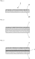
- the polyethylene-laminated film according to the present invention have a laminated structure comprising the above-mentioned polyethylene film 1 and a polyethylene film 2 not irradiated with an electron beam on its both side laminated on the side of surface 20 not irradiated with an electron beam of the polyethylene film 1.
- the electron beam since the electron beam passes through the film, it may cause crosslinking between polyethylene molecular chains even on the side not irradiated with an electron beam, so that the heat sealability on the side not irradiated with an electron beam may be inferior to that of a normal polyethylene film.
- a laminated film having different physical properties (e.g., strength and heat resistance) on the front and back sides can be obtained while using the same material (polyethylene).
- polyethylene polyethylene
- those same as the above can be used. Therefore, even when the laminated film is used, since the same polyethylene is used, recycling can be easily performed.
- the above-mentioned laminated film can also be produced by laminating the two polyethylene films 1 and 2 by a dry lamination method using an adhesive or the like. In this case, irradiation of an electron beam may be carried out before or after the lamination.
- the polyethylene-laminated film can be produced by coextruding the polyethylene films 1 and 2 from an inflation film molding machine or the like to prepare a laminated film, and then irradiating the laminated film with an electron beam on one side.
- the laminated film can be produced simultaneously with film-formation of the polyethylene film 2 by carrying out extrusion coating of a melted polyethylene resin on the polyethylene film 1 which has been irradiated with an electron beam on its one side.
- the electron beam may be irradiated after the film-formation of the polyethylene film 2.
- the polyethylene-laminated film according to the present invention may also comprise a barrier film 3 between the polyethylene films 1 and 2.
- the barrier film can be formed by vapor-depositing a metallic foil such as aluminum foil, a metal such as aluminum, or an inorganic oxide such as aluminum oxide or silicon oxide on the surface of the polyethylene film 2.
- any known conventional methods can be used, including Physical Vapor Depositions (PVDs) such as vacuum vapor deposition, sputtering, and ion plating, as well as Chemical Vapor Depositions (CVDs) such as plasma-enhanced chemical vapor deposition, thermal chemical vapor deposition, and photochemical vapor deposition.
- PVDs Physical Vapor Depositions
- CVDs Chemical Vapor Depositions
- a vacuum vapor deposition method is mainly used and a plasma-enhanced chemical vapor deposition method is also used in some cases.
- a composite film comprising two or more vapor-deposited film layers of different kinds of inorganic oxides formed by using physical and chemical vapor deposition methods in combination, for example, can be used.
- the degree of vacuum in the vapor deposition chamber is preferably about 10 -2 to 10 -8 mbar, particularly about 10 -3 to 10 -7 mbar before introduction of oxygen, and preferably about 10 -1 to 10 -6 mbar, particularly about 10 -2 to 10 -5 mbar after introduction of oxygen.
- the amount of oxygen to be introduced and the like vary depending on, for example, the size of the vapor deposition machine.
- a carrier gas for the oxygen to be introduced inert gas such as argon, helium or nitrogen gas may be used within a range that does not hinder.
- the film transport speed is preferably about 10 to 800 m/min, particularly about 50 to 600 m/min.
- the surface of the vapor-deposited film formed as described above may be treated with oxygen plasma.
- the amount of oxygen to be introduced for the oxygen plasma treatment varies depending on, for example, the size of the vapor deposition machine, and is usually about 50 sccm to 2000 sccm, particularly preferably about 300 sccm to 800 sccm.
- sccm means the average amount (cc) of oxygen introduced per minute at the standard temperature and pressure (STP: 0°C, 1 atm).
- STP standard temperature and pressure
- inert gas such as argon, helium or nitrogen gas may be used within a range that does not hinder.
- Such treatment on the vapor-deposited film (barrier film) improves the adhesion when the polyethylene film 1 is laminated to the barrier film 3 formed on the polyethylene film 2.
- the barrier film 3 is formed on the side of face 20 not irradiated with an electron beam of the polyethylene film 1 as described above, and then a melted polyethylene resin is extrusion-coated on the barrier film, so that a laminated film can be produced simultaneously with film-formation of the polyethylene film 2.
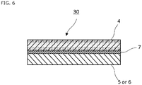
- FIG. 4 is a schematic cross-sectional view of the laminate 30 according to the present invention.
- the laminate 30 comprises a polyethylene film substrate 4 irradiated with an electron beam on its both sides and a polyethylene film layer 5 not irradiated with an electron beam on its both sides.
- the laminate 30 comprises a polyethylene film substrate 4 irradiated with an electron beam on its both sides and a polyethylene film layer 6 not irradiated with an electron beam on its one side.
- the laminate is preferably produced such that the surface of the polyethylene film layer not irradiated with an electron beam is arranged on the outermost surface.
- the surface of the polyethylene film layer not irradiated with an electron beam arranged on the outermost surface can maintain the heat sealability of the laminate.
- the laminate may also comprise a barrier film 7 between the polyethylene film substrate 4 irradiated with an electron beam on its both sides and the polyethylene film layer 5 or 6.
- the polyethylene film substrate provided on the laminate according to the present invention comprises a polyethylene film and is irradiated with an electron beam on its both sides.
- the polyethylene film substrate may have a single layer or multilayer structure.
- the laminate comprises such a polyethylene film substrate, so that the surface of the laminate can have improved heat resistance and strength, satisfying the physical properties required as the outer layer of a package or the like.
- the same materials as those used for the above-mentioned polyethylene film can be used.
- the polyethylene film substrate can be obtained by melting the above-mentioned polyethylene resin and allowing it to form a film by a melt extrusion molding method such as inflation molding or T-die molding.
- the polyethylene film substrate having a multilayer structure can also be produced by laminating two polyethylene film substrates by a dry lamination method using an adhesive or the like and then irradiating it with an electron beam. In order to omit the steps of adhesive application and lamination, it can be produced by coextrusion from an inflation film molding machine or the like followed by electron beam irradiation. It can also be produced by an extrusion coating method.
- the polyethylene film substrate provided on the laminate according to the present invention is irradiated with an electron beam on its both sides.
- the electron beam irradiation may be applied on each of the sides, or on one side in which the electron beam penetrates the polyethylene film substrate and improves the crosslink density on the side opposite to the irradiated side.
- the irradiation energy of the electron beam is changed as appropriate depending on the use of the intended package.
- the dose of the electron beam irradiated on the polyethylene film substrate is preferably in the range of 10 to 2,000 kGy, more preferably 10 to 1,000 kGy, and still more preferably 50 to 1,000 kGy.
- the acceleration voltage of the electron beam, when the electron beam is irradiated on one side, is preferably in the range of 20 to 750 kV, more preferably 25 to 400 keV, particularly preferably 50 to 400 kV.
- the acceleration voltage of the electron beam when the electron beam is irradiated on both sides, is preferably in the range of 20 to 750 kV, more preferably 25 to 400 kV, particularly preferably 30 to 300 kV, or may be in the range of 20 to 200 kV.
- the oxygen concentration in the electron beam irradiation device is preferably 500 ppm or less, more preferably 100 ppm or less.
- the thickness of the polyethylene film substrate may be optionally selected depending on its use, and is usually about 15 ⁇ m to 150 ⁇ m, preferably about 20 ⁇ m to 130 ⁇ m, more preferably about 20 ⁇ m to 100 ⁇ m.
- the film thickness of the polyethylene film substrate can be appropriately adjusted by changing, for example, the screw rotation speed of the melt extruder and the rotation speed of the cooling roll in the production of the above-mentioned polyethylene film.
- the polyethylene film layer provided on the laminate according to the present invention comprises a polyethylene film, wherein its at least one side is not irradiated with an electron beam.
- the laminate comprises such a layer, so that the laminate can comprise a substrate and a layer provided on the substrate each having different physical properties (e.g., strength and heat resistance) while using the same material (polyethylene).
- the laminate can comprise a substrate and a layer provided on the substrate each having different physical properties (e.g., strength and heat resistance) while using the same material (polyethylene).
- the same materials as those used for the above-mentioned polyethylene film can be used. Therefore, since the same polyethylene is used, recycling can be easily performed.
- the thickness of the polyethylene film layer may be optionally selected depending on its use, and is usually about 15 ⁇ m to 100 ⁇ m, preferably about 20 ⁇ m to 200 ⁇ m, more preferably about 25 ⁇ m to 160 ⁇ m.
- polyethylene film substrate and polyethylene film layer can also be produced by lamination via a dry lamination method using an adhesive or the like, extrusion coating of a melted polyethylene resin on the polyethylene film substrate, in order to omit the steps of adhesive application and lamination, can provide a laminate simultaneously with film-formation of the polyethylene film layer.
- a laminate comprising the polyethylene film substrate and the polyethylene film layer may be produced by coextrusion, and then irradiated with an electron beam on its only one side.
- the polyethylene film layer is one irradiated with an electron beam on its one side
- the polyethylene film layer is preferably laminated with the polyethylene film substrate such that the surface of the polyethylene film layer not irradiated with an electron beam is arranged on the outermost surface.
- the laminate of the present invention may optionally comprise a barrier film between the polyethylene film substrate and the polyethylene film layer.
- the barrier film is as described above.
- the package according to the present invention comprises the above-mentioned polyethylene film or laminate, wherein the side not irradiated with an electron beam of the polyethylene film or the side having the heat sealability of the polyethylene film layer provided in the laminate faces inward.
- such a packaging material can be produced by folding in half and superposing the polyethylene film so that the side not irradiated with an electron beam faces inward and heat-sealing the edges.
- the polyethylene-laminated film described above may be used.
- the package can be produced by folding in half and superposing the polyethylene-laminated film so that the side of the polyethylene film 2 not irradiated with an electron beam on its both sides faces inward and heat-sealing the edges.
- Various types of packages can be produced by sealing methods, for example, a side sealing type, a two-side sealing type, a three-side sealing type, a four-side sealing type, an envelope sealing type, a butt-seam sealing type (pillow sealing type), a gusset sealing type, a flat-bottom sealing type, a square-bottom sealing type, a gusset type, or other heat-sealing types.
- Others for example, self-standing packaging bag (standing pouch) are also possible.
- the methods for heat sealing include known methods such as bar sealing, rotary sealing, belt sealing, impulse sealing, high-frequency sealing, or ultrasonic sealing.
- a film consisting of one material can be suitably used as a packaging film, since the polyethylene film on the side irradiated with an electron beam can satisfy the physical properties such as strength and dimensional stability required as the outer film of a package while the polyethylene film on the side not irradiated with an electron beam can maintain heat sealability.
- the package is produced using a film consisting of one material, recycling of the material can be easily performed after use of the package.
- a linear low-density polyethylene (EVOLUE SP2020, produced by Primepolymer Co.) was used to obtain an unstretched polyethylene film 1A having a thickness of 120 ⁇ m using an inflation film molding machine.
- An unstretched polyethylene film 1B was obtained in the same manner as described above except that the film molding conditions were changed and the thickness was changed to 80 ⁇ m.
- unstretched polyethylene films 1C and 1D having a thickness of 120 ⁇ m and 80 ⁇ m, respectively, were obtained in the same manner as described above except that a low density polyethylene (LD2420H, produced by PTT Chemical Co.) was used.
- LD2420H low density polyethylene
- the one side of the prepared polyethylene film 1A was irradiated with an electron beam using an electron beam irradiation device (line-irradiation type low-energy electron beam irradiation device EES-L-DP01, produced by Hamamatsu Photonics Co., Ltd.) under the following conditions to obtain a polyethylene film 1-1 irradiated with an electron beam only on one side thereof.
- an electron beam irradiation device line-irradiation type low-energy electron beam irradiation device EES-L-DP01, produced by Hamamatsu Photonics Co., Ltd.
- a polyethylene film 1-2 was obtained in the same manner as in Example 1-1, except that the exposure dose of the electron beam was change to 430 kGy in Example 1-1.
- a polyethylene film 1-3 was obtained in the same manner as in Example 1-2, except that an unstretched polyethylene film 1B was used as the polyethylene film in Example 1-2.
- a polyethylene film 1-4 was obtained in the same manner as in Example 1-1, except that an unstretched polyethylene film 1C was used as the polyethylene film in Example 1-1.
- a polyethylene film 1-5 was obtained in the same manner as in Example 1-4, except that the exposure dose of the electron beam was change to 430 kGy in Example 1-4.
- a polyethylene film 1-6 was obtained in the same manner as in Example 1-5, except that an unstretched polyethylene film 1D was used as the polyethylene film in Example 1-5.
- the unstretched polyethylene film A before irradiation with an electron beam in Example 1-1 was taken as a polyethylene film 1-7.
- Each of the polyethylene films obtained in Examples 1-1 to 1-6 and Comparative Example 1-1 was cut to 10 cm x 10 cm to prepare a sample piece.
- the sample piece was folded in half so that the side not irradiated with an electron beam was inside, and a 1 cm x 10 cm area of this sample piece was heat-sealed using a heat-sealing tester at a temperature of 180°C and a pressure of 1 kgf/cm 2 for 1 second. Since both sides of the polyethylene film 7 from Comparative Example 1 was not irradiated with an electron beam, the film was folded in half without distinction between front and back and heat-sealed.
- the obtained heat-sealed sample piece was visually evaluated for appearance. Evaluation criteria were as follows:
- a linear low-density polyethylene (EVOLUE SP2020, produced by Primepolymer Co.) was used to obtain an unstretched polyethylene film 2A having a thickness of 25 ⁇ m using an inflation film molding machine.
- An unstretched polyethylene film 2B was obtained in the same manner as described above except that the film molding conditions were changed and the thickness was changed to 50 ⁇ m.
- unstretched polyethylene films 2C and 2D having a thickness of 25 ⁇ m and 50 ⁇ m, respectively, were obtained in the same manner as described above except that a low density polyethylene (LD2420H, produced by PTT Chemical Co.) was used.
- LD2420H low density polyethylene
- the both sides of the obtained polyethylene film 2A was irradiated with an electron beam using an electron beam irradiation device (LB1023, produced by Eye Electron Beam Co., Ltd.) under the following conditions to obtain a polyethylene film substrate 2-1 irradiated with an electron beam on its both sides.
- an electron beam irradiation device LB1023, produced by Eye Electron Beam Co., Ltd.
- a polyethylene film substrate 2-2 was obtained in the same manner as in preparation of the polyethylene film substrate 2-1, except that the exposure dose was changed to 500 kGy.
- Polyethylene film substrates 2-3, 2-4 and 2-5 were obtained in the same manner as in preparation of the polyethylene film substrate 2-1, except that the polyethylene film 2A was substituted with polyethylene films 2B, 2C and 2D, respectively.
- a linear low-density polyethylene (EVOLUE SP2020, Primepolymer) was extrusion-coated on the obtained polyethylene film substrate 2-1 to form a polyethylene film layer having a thickness of 60 ⁇ m, thereby obtaining a laminate 2-1.
- a laminate 2-2 was obtained in the same manner as in Example 2-1, except that the thickness of the polyethylene film layer was changed to 100 ⁇ m in Example 2-1.
- a laminate 2-3 was obtained in the same manner as in Example 2-1, except that the substrate was substituted with the polyethylene film substrate 2-2 in Example 2-1.
- a laminate 2-4 was obtained in the same manner as in Example 2-1, except that the substrate was substituted with the polyethylene film substrate 2-3 and the thickness of the polyethylene film layer was changed to 100 ⁇ m in Example 2-1.
- a laminate 2-5 was obtained in the same manner as in Example 2-1, except that the substrate was substituted with the polyethylene film substrate 2-4 in Example 2-1.
- a laminate 2-6 was obtained in the same manner as in Example 2-1, except that the substrate was substituted with the polyethylene film substrate 2-5 in Example 2-1.
- a laminate 2-7 was obtained in the same manner as in Example 2-1, except that an unstretched polyethylene film A before irradiation with an electron beam was used as a polyethylene film substrate in Example 2-1.
- Each of the laminates obtained in the Examples 2-1 to 2-6 and the Comparative Example 2-1 was cut to 10 cm x 10 cm to prepare a sample piece.
- the sample piece was folded in half so that the side of polyethylene film layer was inside, and a 1 cm x 10 cm area of this sample piece was heat-sealed using a heat-sealing tester at a temperature of 180°C and a pressure of 1 kgf/cm 2 for 1 second.
- the obtained heat-sealed sample piece was visually evaluated for appearance. Evaluation criteria were as follows:
Landscapes
- Chemical & Material Sciences (AREA)
- Health & Medical Sciences (AREA)
- Chemical Kinetics & Catalysis (AREA)
- Medicinal Chemistry (AREA)
- Polymers & Plastics (AREA)
- Organic Chemistry (AREA)
- Engineering & Computer Science (AREA)
- Mechanical Engineering (AREA)
- Laminated Bodies (AREA)
- Wrappers (AREA)
- Treatments Of Macromolecular Shaped Articles (AREA)
Applications Claiming Priority (3)
| Application Number | Priority Date | Filing Date | Title |
|---|---|---|---|
| JP2015213095A JP6740592B2 (ja) | 2015-10-29 | 2015-10-29 | 積層体およびそれを用いた包装体 |
| JP2015213086A JP6846000B2 (ja) | 2015-10-29 | 2015-10-29 | ポリエチレンフィルムおよびそれを用いた包装体 |
| PCT/JP2016/082123 WO2017073751A1 (ja) | 2015-10-29 | 2016-10-28 | ポリエチレンフィルム、積層体およびこれらを用いた包装体 |
Publications (2)
| Publication Number | Publication Date |
|---|---|
| EP3369769A1 true EP3369769A1 (de) | 2018-09-05 |
| EP3369769A4 EP3369769A4 (de) | 2019-03-13 |
Family
ID=58630348
Family Applications (1)
| Application Number | Title | Priority Date | Filing Date |
|---|---|---|---|
| EP16859979.3A Withdrawn EP3369769A4 (de) | 2015-10-29 | 2016-10-28 | Polyethylenfolie, laminat und verpackung mit verwendung davon |
Country Status (3)
| Country | Link |
|---|---|
| US (1) | US20180345633A1 (de) |
| EP (1) | EP3369769A4 (de) |
| WO (1) | WO2017073751A1 (de) |
Cited By (1)
| Publication number | Priority date | Publication date | Assignee | Title |
|---|---|---|---|---|
| EP4129672A4 (de) * | 2020-03-30 | 2024-05-01 | Sumitomo Bakelite Co.Ltd. | Verbundfolie |
Families Citing this family (8)
| Publication number | Priority date | Publication date | Assignee | Title |
|---|---|---|---|---|
| WO2018221495A1 (ja) * | 2017-05-30 | 2018-12-06 | 大日本印刷株式会社 | ポリエチレン共押フィルム、ポリエチレン積層フィルムおよびこれらを用いた包装材料 |
| US12391028B2 (en) | 2018-09-07 | 2025-08-19 | Amcor Flexibles North America, Inc. | Recyclable films and packaging |
| JP2020157517A (ja) * | 2019-03-25 | 2020-10-01 | 大日本印刷株式会社 | スパウト付き包装袋用積層体および包装袋 |
| JP7576232B2 (ja) * | 2019-03-28 | 2024-10-31 | 大日本印刷株式会社 | 積層体、包装材料、包装袋およびスタンドパウチ |
| JP2020203405A (ja) * | 2019-06-14 | 2020-12-24 | 大日本印刷株式会社 | 積層体および包装袋 |
| JP2020203406A (ja) * | 2019-06-14 | 2020-12-24 | 大日本印刷株式会社 | 積層体および包装材料 |
| JP7310342B2 (ja) * | 2019-06-14 | 2023-07-19 | 大日本印刷株式会社 | フィルム、該フィルムから構成される包装袋、該フィルムを備える積層体及び該積層体から構成される包装袋 |
| US12583212B2 (en) * | 2022-11-20 | 2026-03-24 | Energy Sciences Inc. | Functional and recyclable materials with electron beam crosslinking for various packaging applications |
Family Cites Families (17)
| Publication number | Priority date | Publication date | Assignee | Title |
|---|---|---|---|---|
| JPS51126269A (en) * | 1975-04-24 | 1976-11-04 | Sekisui Chemical Co Ltd | Manufacturing of thermal contractive films |
| DE2925205A1 (de) * | 1979-06-22 | 1981-02-05 | Bayer Ag | Dampfsterilisierbare, siegelbare folien |
| JPH02134246A (ja) * | 1988-11-15 | 1990-05-23 | Tonen Sekiyukagaku Kk | ヒートシール性ポリエチレン架橋延伸フイルム及びその製造方法 |
| JP2987777B2 (ja) * | 1990-06-08 | 1999-12-06 | 旭化成工業株式会社 | 熱収縮性多層フィルム及びその製造方法 |
| JPH04255340A (ja) * | 1991-02-06 | 1992-09-10 | Toppan Printing Co Ltd | 包装袋の製造方法 |
| JP2653337B2 (ja) * | 1993-03-24 | 1997-09-17 | 東洋製罐株式会社 | 二重包装体 |
| JP3315518B2 (ja) * | 1994-03-31 | 2002-08-19 | 旭化成株式会社 | 熱収縮性多層フィルム |
| JP2004218101A (ja) * | 2003-01-10 | 2004-08-05 | Toyo Ink Mfg Co Ltd | 表面改質プラスチック材およびその製造方法 |
| JP2005225118A (ja) * | 2004-02-13 | 2005-08-25 | Fuji Seal International Inc | プラスチックラベル |
| JP5289263B2 (ja) * | 2009-09-30 | 2013-09-11 | 旭化成イーマテリアルズ株式会社 | 樹脂封止シート及びそれを用いた太陽電池モジュール |
| JP2011073337A (ja) * | 2009-09-30 | 2011-04-14 | Asahi Kasei E-Materials Corp | 樹脂封止シート |
| JP5934646B2 (ja) * | 2010-08-11 | 2016-06-15 | 大倉工業株式会社 | 端子接着用テープの製造方法、および端子接着用テープ |
| WO2013001606A1 (ja) * | 2011-06-28 | 2013-01-03 | 大日本印刷株式会社 | フィルム基材の接着方法 |
| JP2013180420A (ja) * | 2012-02-29 | 2013-09-12 | Dainippon Printing Co Ltd | 積層体およびその製造方法 |
| JP6038600B2 (ja) * | 2012-11-09 | 2016-12-07 | 大倉工業株式会社 | 電池外包材用シーラントフィルムとその製造方法 |
| JP6368478B2 (ja) * | 2013-11-08 | 2018-08-01 | 旭化成株式会社 | ポリエチレン系架橋シュリンクフィルム |
| WO2017018479A1 (ja) * | 2015-07-28 | 2017-02-02 | 大日本印刷株式会社 | ポリエチレンフィルム、積層体およびこれらを用いた包装体 |
-
2016
- 2016-10-28 US US15/771,440 patent/US20180345633A1/en not_active Abandoned
- 2016-10-28 WO PCT/JP2016/082123 patent/WO2017073751A1/ja not_active Ceased
- 2016-10-28 EP EP16859979.3A patent/EP3369769A4/de not_active Withdrawn
Cited By (1)
| Publication number | Priority date | Publication date | Assignee | Title |
|---|---|---|---|---|
| EP4129672A4 (de) * | 2020-03-30 | 2024-05-01 | Sumitomo Bakelite Co.Ltd. | Verbundfolie |
Also Published As
| Publication number | Publication date |
|---|---|
| EP3369769A4 (de) | 2019-03-13 |
| US20180345633A1 (en) | 2018-12-06 |
| WO2017073751A1 (ja) | 2017-05-04 |
Similar Documents
| Publication | Publication Date | Title |
|---|---|---|
| US20260015474A1 (en) | Polyethylene film, laminate and package using the same | |
| EP3369769A1 (de) | Polyethylenfolie, laminat und verpackung mit verwendung davon | |
| JP6740592B2 (ja) | 積層体およびそれを用いた包装体 | |
| JP6826771B2 (ja) | ポリエチレン積層フィルムおよびこれを用いた包装体 | |
| JP6826770B2 (ja) | ポリエチレン共押フィルムおよびこれを用いた包装体 | |
| EP2558531B1 (de) | Polymermischungen und filme | |
| JP6969161B2 (ja) | ポリエチレン積層フィルムおよびこれを用いた包装材料 | |
| WO2018221495A1 (ja) | ポリエチレン共押フィルム、ポリエチレン積層フィルムおよびこれらを用いた包装材料 | |
| EP0706455A1 (de) | Strukturverbesserung von polymeren hergestellt mit einlagigen katalysatoren | |
| JP6969160B2 (ja) | ポリエチレン共押フィルムおよびこれを用いた包装材料 | |
| JP6826769B2 (ja) | ポリエチレン共押フィルムおよびこれを用いた包装体 | |
| JP6826768B2 (ja) | ポリエチレン積層フィルムおよびこれを用いた包装体 | |
| EP1629973B1 (de) | Laminat | |
| JP6846000B2 (ja) | ポリエチレンフィルムおよびそれを用いた包装体 | |
| JP6579430B2 (ja) | 積層体およびそれを用いた包装体 | |
| JP6759537B2 (ja) | ポリエチレンフィルムおよびそれを用いた包装体 | |
| JP6597023B2 (ja) | ポリエチレン積層フィルムおよびそれを用いた包装体 | |
| JP6802992B2 (ja) | ポリエチレンフィルムおよびそれを用いた包装体 | |
| EP4678398A1 (de) | Mehrschichtige gestreckte folie | |
| JP4219837B2 (ja) | バリア性包装袋またはバリア性包装容器およびその製造方法 | |
| JP7005901B2 (ja) | 中間層用樹脂組成物及び包装用フィルム及び液体包装袋 | |
| JP4689980B2 (ja) | 多層フィルムおよび成形体 | |
| EP4516841A1 (de) | Polymermischung zur herstellung eines biorientierten polymerfilms | |
| WO2002042062A2 (en) | Poultry shrink bags with antiblock additives | |
| AU2002239314A1 (en) | Poultry shrink bags with antiblock additives |
Legal Events
| Date | Code | Title | Description |
|---|---|---|---|
| PUAI | Public reference made under article 153(3) epc to a published international application that has entered the european phase |
Free format text: ORIGINAL CODE: 0009012 |
|
| 17P | Request for examination filed |
Effective date: 20180507 |
|
| AK | Designated contracting states |
Kind code of ref document: A1 Designated state(s): AL AT BE BG CH CY CZ DE DK EE ES FI FR GB GR HR HU IE IS IT LI LT LU LV MC MK MT NL NO PL PT RO RS SE SI SK SM TR |
|
| AX | Request for extension of the european patent |
Extension state: BA ME |
|
| RAP1 | Party data changed (applicant data changed or rights of an application transferred) |
Owner name: DAI NIPPON PRINTING CO., LTD. |
|
| DAV | Request for validation of the european patent (deleted) | ||
| DAX | Request for extension of the european patent (deleted) | ||
| A4 | Supplementary search report drawn up and despatched |
Effective date: 20190211 |
|
| RIC1 | Information provided on ipc code assigned before grant |
Ipc: B32B 27/16 20060101ALI20190205BHEP Ipc: B32B 27/32 20060101ALI20190205BHEP Ipc: B32B 27/30 20060101ALI20190205BHEP Ipc: B65D 65/38 20060101ALI20190205BHEP Ipc: B32B 5/14 20060101ALI20190205BHEP Ipc: B32B 27/00 20060101ALI20190205BHEP Ipc: C08J 7/00 20060101AFI20190205BHEP |
|
| 17Q | First examination report despatched |
Effective date: 20200129 |
|
| GRAP | Despatch of communication of intention to grant a patent |
Free format text: ORIGINAL CODE: EPIDOSNIGR1 |
|
| INTG | Intention to grant announced |
Effective date: 20200429 |
|
| STAA | Information on the status of an ep patent application or granted ep patent |
Free format text: STATUS: THE APPLICATION IS DEEMED TO BE WITHDRAWN |
|
| 18D | Application deemed to be withdrawn |
Effective date: 20200910 |