EP3369113B1 - Image pick-up apparatus - Google Patents
Image pick-up apparatus Download PDFInfo
- Publication number
- EP3369113B1 EP3369113B1 EP16790735.1A EP16790735A EP3369113B1 EP 3369113 B1 EP3369113 B1 EP 3369113B1 EP 16790735 A EP16790735 A EP 16790735A EP 3369113 B1 EP3369113 B1 EP 3369113B1
- Authority
- EP
- European Patent Office
- Prior art keywords
- light
- opto
- unit
- pixel
- electronic converter
- Prior art date
- Legal status (The legal status is an assumption and is not a legal conclusion. Google has not performed a legal analysis and makes no representation as to the accuracy of the status listed.)
- Active
Links
Images


Classifications
-
- H—ELECTRICITY
- H04—ELECTRIC COMMUNICATION TECHNIQUE
- H04N—PICTORIAL COMMUNICATION, e.g. TELEVISION
- H04N25/00—Circuitry of solid-state image sensors [SSIS]; Control thereof
- H04N25/50—Control of the SSIS exposure
- H04N25/57—Control of the dynamic range
- H04N25/58—Control of the dynamic range involving two or more exposures
- H04N25/581—Control of the dynamic range involving two or more exposures acquired simultaneously
- H04N25/585—Control of the dynamic range involving two or more exposures acquired simultaneously with pixels having different sensitivities within the sensor, e.g. fast or slow pixels or pixels having different sizes
-
- H—ELECTRICITY
- H04—ELECTRIC COMMUNICATION TECHNIQUE
- H04N—PICTORIAL COMMUNICATION, e.g. TELEVISION
- H04N25/00—Circuitry of solid-state image sensors [SSIS]; Control thereof
- H04N25/70—SSIS architectures; Circuits associated therewith
- H04N25/76—Addressed sensors, e.g. MOS or CMOS sensors
- H04N25/77—Pixel circuitry, e.g. memories, A/D converters, pixel amplifiers, shared circuits or shared components
- H04N25/771—Pixel circuitry, e.g. memories, A/D converters, pixel amplifiers, shared circuits or shared components comprising storage means other than floating diffusion
-
- H—ELECTRICITY
- H10—SEMICONDUCTOR DEVICES; ELECTRIC SOLID-STATE DEVICES NOT OTHERWISE PROVIDED FOR
- H10F—INORGANIC SEMICONDUCTOR DEVICES SENSITIVE TO INFRARED RADIATION, LIGHT, ELECTROMAGNETIC RADIATION OF SHORTER WAVELENGTH OR CORPUSCULAR RADIATION
- H10F39/00—Integrated devices, or assemblies of multiple devices, comprising at least one element covered by group H10F30/00, e.g. radiation detectors comprising photodiode arrays
- H10F39/10—Integrated devices
- H10F39/12—Image sensors
- H10F39/18—Complementary metal-oxide-semiconductor [CMOS] image sensors; Photodiode array image sensors
- H10F39/182—Colour image sensors
-
- H—ELECTRICITY
- H10—SEMICONDUCTOR DEVICES; ELECTRIC SOLID-STATE DEVICES NOT OTHERWISE PROVIDED FOR
- H10F—INORGANIC SEMICONDUCTOR DEVICES SENSITIVE TO INFRARED RADIATION, LIGHT, ELECTROMAGNETIC RADIATION OF SHORTER WAVELENGTH OR CORPUSCULAR RADIATION
- H10F39/00—Integrated devices, or assemblies of multiple devices, comprising at least one element covered by group H10F30/00, e.g. radiation detectors comprising photodiode arrays
- H10F39/10—Integrated devices
- H10F39/12—Image sensors
- H10F39/191—Photoconductor image sensors
-
- H—ELECTRICITY
- H10—SEMICONDUCTOR DEVICES; ELECTRIC SOLID-STATE DEVICES NOT OTHERWISE PROVIDED FOR
- H10F—INORGANIC SEMICONDUCTOR DEVICES SENSITIVE TO INFRARED RADIATION, LIGHT, ELECTROMAGNETIC RADIATION OF SHORTER WAVELENGTH OR CORPUSCULAR RADIATION
- H10F39/00—Integrated devices, or assemblies of multiple devices, comprising at least one element covered by group H10F30/00, e.g. radiation detectors comprising photodiode arrays
- H10F39/80—Constructional details of image sensors
- H10F39/802—Geometry or disposition of elements in pixels, e.g. address-lines or gate electrodes
- H10F39/8023—Disposition of the elements in pixels, e.g. smaller elements in the centre of the imager compared to larger elements at the periphery
-
- H—ELECTRICITY
- H10—SEMICONDUCTOR DEVICES; ELECTRIC SOLID-STATE DEVICES NOT OTHERWISE PROVIDED FOR
- H10F—INORGANIC SEMICONDUCTOR DEVICES SENSITIVE TO INFRARED RADIATION, LIGHT, ELECTROMAGNETIC RADIATION OF SHORTER WAVELENGTH OR CORPUSCULAR RADIATION
- H10F39/00—Integrated devices, or assemblies of multiple devices, comprising at least one element covered by group H10F30/00, e.g. radiation detectors comprising photodiode arrays
- H10F39/80—Constructional details of image sensors
- H10F39/805—Coatings
- H10F39/8053—Colour filters
-
- H—ELECTRICITY
- H10—SEMICONDUCTOR DEVICES; ELECTRIC SOLID-STATE DEVICES NOT OTHERWISE PROVIDED FOR
- H10F—INORGANIC SEMICONDUCTOR DEVICES SENSITIVE TO INFRARED RADIATION, LIGHT, ELECTROMAGNETIC RADIATION OF SHORTER WAVELENGTH OR CORPUSCULAR RADIATION
- H10F39/00—Integrated devices, or assemblies of multiple devices, comprising at least one element covered by group H10F30/00, e.g. radiation detectors comprising photodiode arrays
- H10F39/80—Constructional details of image sensors
- H10F39/805—Coatings
- H10F39/8057—Optical shielding
-
- H—ELECTRICITY
- H10—SEMICONDUCTOR DEVICES; ELECTRIC SOLID-STATE DEVICES NOT OTHERWISE PROVIDED FOR
- H10F—INORGANIC SEMICONDUCTOR DEVICES SENSITIVE TO INFRARED RADIATION, LIGHT, ELECTROMAGNETIC RADIATION OF SHORTER WAVELENGTH OR CORPUSCULAR RADIATION
- H10F39/00—Integrated devices, or assemblies of multiple devices, comprising at least one element covered by group H10F30/00, e.g. radiation detectors comprising photodiode arrays
- H10F39/80—Constructional details of image sensors
- H10F39/806—Optical elements or arrangements associated with the image sensors
- H10F39/8067—Reflectors
-
- H—ELECTRICITY
- H10—SEMICONDUCTOR DEVICES; ELECTRIC SOLID-STATE DEVICES NOT OTHERWISE PROVIDED FOR
- H10F—INORGANIC SEMICONDUCTOR DEVICES SENSITIVE TO INFRARED RADIATION, LIGHT, ELECTROMAGNETIC RADIATION OF SHORTER WAVELENGTH OR CORPUSCULAR RADIATION
- H10F39/00—Integrated devices, or assemblies of multiple devices, comprising at least one element covered by group H10F30/00, e.g. radiation detectors comprising photodiode arrays
- H10F39/80—Constructional details of image sensors
- H10F39/807—Pixel isolation structures
-
- H—ELECTRICITY
- H10—SEMICONDUCTOR DEVICES; ELECTRIC SOLID-STATE DEVICES NOT OTHERWISE PROVIDED FOR
- H10F—INORGANIC SEMICONDUCTOR DEVICES SENSITIVE TO INFRARED RADIATION, LIGHT, ELECTROMAGNETIC RADIATION OF SHORTER WAVELENGTH OR CORPUSCULAR RADIATION
- H10F39/00—Integrated devices, or assemblies of multiple devices, comprising at least one element covered by group H10F30/00, e.g. radiation detectors comprising photodiode arrays
- H10F39/80—Constructional details of image sensors
- H10F39/802—Geometry or disposition of elements in pixels, e.g. address-lines or gate electrodes
- H10F39/8027—Geometry of the photosensitive area
-
- H—ELECTRICITY
- H10—SEMICONDUCTOR DEVICES; ELECTRIC SOLID-STATE DEVICES NOT OTHERWISE PROVIDED FOR
- H10F—INORGANIC SEMICONDUCTOR DEVICES SENSITIVE TO INFRARED RADIATION, LIGHT, ELECTROMAGNETIC RADIATION OF SHORTER WAVELENGTH OR CORPUSCULAR RADIATION
- H10F39/00—Integrated devices, or assemblies of multiple devices, comprising at least one element covered by group H10F30/00, e.g. radiation detectors comprising photodiode arrays
- H10F39/80—Constructional details of image sensors
- H10F39/806—Optical elements or arrangements associated with the image sensors
- H10F39/8063—Microlenses
Definitions
- the present invention relates to an image pick-up apparatus capable of extending the dynamic range of the image pick-up apparatus.
- an in-pixel memory method in which a memory in which the charge overflowing from a photodiode is accumulated is provided on each pixel in an image pick-up apparatus so that the amount of charge accumulated in an exposure period is increased and the increase extends the dynamic range of the image pick-up apparatus (for example, see Patent Literature 3).
- Patent Literature 4 relates to a 3D color image sensor including a substrate having a plurality of first photodiodes and a plurality of second photodiodes.
- a light filter array is disposed on the first and second photodiodes.
- the sensitive area of the first photodiodes is larger than the sensitive area of the second photodiodes.
- First and second photodiodes are isolated by an insulator which may be formed as shallow trench isolations. Further examples of solid-state imaging devices are disclosed in Patent Literature 5 to 10.
- PTL 10 discloses an imaging device provided with a plurality of pixel units, each pixel unit comprising a low sensitivity pixel and a high sensitivity pixel.
- Polarization grids are provided on the low sensitivity pixels.
- the low sensitivity pixels are off-set within a pixel group comprising two pixel units.
- the polarization grids are arranged in a same direction.
- Increasing the number of divided times in the time division method or increasing the number of divided spaces in the space division method can extend the dynamic range of an image pick-up apparatus.
- the increase in number of divided times or divided spaces degrades the quality of images, for example, due to the occurrence of an artifact or the decrease in resolution.
- the limit of the memory capacity limits the extension of the dynamic range in the in-pixel memory method.
- the invention provides an imaging device in accordance with claim 1.
- the invention provides an electronic apparatus in accordance with claim 11. Further aspects of the invention are set forth in the dependent claims, the drawings and the following description of embodiments.
- An image pick-up apparatus according to the invention is defined in claim 1.
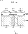
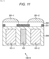
- a lens used to collect light entering the second opto-electronic converter may not be formed on the second opto-electronic converter.
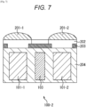
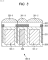
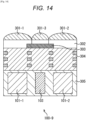
- the image pick-up apparatus may be a backside-illumination image sensor.
- the image pick-up apparatus may be a front-side-illumination image sensor.
- the light-blocking film may be formed on a lower or upper side of a wiring layer formed on the second opto-electronic converter.
- the light-blocking film may be an amorphous silicon film, a polysilicon film, a Ge film, a GaN film, a CdTe film, a GaAs film, an InP film, a CuInSe2 film, Cu2S, a CIGS film, a non-conductive carbon film, a black resist film, an organic opto-electronic conversion film, or a metal film.
- the dynamic range of an image pick-up apparatus can be extended without the degradation of the quality of images.
- FIG. 24C An embodiment of the invention is depicted in Figure 24C .
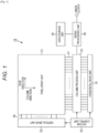
- Fig. 1 is a schematic system configuration diagram of a CMOS image sensor that is an image pick-up apparatus using the present technology, for example, a pick-up apparatus using an X-Y address system.
- the CMOS image sensor is an image sensor applying or partially using a CMOS process.
- a CMOS image sensor 10 includes a pixel array unit 11 formed on a semiconductor substrate (chip) (not illustrated), and a peripheral circuit unit integrated with the pixel array unit 11 on the same semiconductor substrate.
- the peripheral circuit unit includes, for example, a vertical drive unit 12, a column processing unit 13, a horizontal drive unit 14, and a system control unit 15.
- the CMOS image sensor 10 further includes a signal processing unit 18, and a data storage unit 19.
- the signal processing unit 18 and the data storage unit 19 can be mounted on the same substrate on which the CMOS image sensor 10 is mounted, or can be placed on a different substrate from the substrate on which the CMOS image sensor 10 is mounted. Additionally, the process that each of the signal processing unit 18 and the data storage unit 19 performs can be processed by an external signal processing unit provided on a different substrate from the substrate on which the CMOS image sensor 10 is mounted, such as a Digital Signal Processor (DSP) circuit or by software.
- DSP Digital Signal Processor
- unit pixels (hereinafter, sometimes referred to merely as "pixels") are arranged in a row direction and a column direction, in other words, two-dimensionally arranged in rows and columns.
- the unit pixel includes an opto-electronic converter that generates and accumulates the charge corresponding to the amount of light that the opto-electronic converter receives.
- the row direction is a direction in which pixels are arranged in a pixel row (namely, a horizontal direction)
- the column direction is a direction in which pixels are arranged in a pixel column (namely, a vertical direction).
- pixel drive lines 16 are distributed to the pixel rows in the row direction, respectively, and vertical signal lines 17 are distributed to pixel columns in the column direction, respectively, in the pixel arrangement in rows and columns.
- the pixel drive line 16 transmits a drive signal used for the drive to read a signal from a pixel.
- Fig. 1 illustrates the pixel drive line 16 as a wire. However, the number of wires is not limited to one.
- First ends of the pixel drive lines 16 are connected to output terminals of the vertical drive unit 12 that corresponds to the rows, respectively.
- the vertical drive unit 12 includes a shift register or an address decoder, and drives the pixels in the pixel array unit 11, for example, simultaneously or row by row.
- the vertical drive unit 12 cooperates with a system control unit 15 that controls the vertical drive unit 12 so as to work as a drive unit that controls the operation of each pixel in the pixel array unit 11.
- the illustration of the concrete configuration of the vertical drive unit 12 is omitted.
- the vertical drive unit 12 generally includes two scanning systems; a readout scanning system, and a discharge scanning system.
- the readout scanning system sequentially selects and scans the unit pixels in the pixel array unit 11 row by row so as to read signals from the unit pixels.
- the signal read from a unit pixel is an analog signal.
- the discharge scanning system scans a row in discharge scanning the exposure period earlier than the time when the readout scanning system reads and scans the row in readout scanning.
- the discharge scanning by the discharge scanning system discharges unnecessary charge from the opto-electronic converters of the unit pixels in the read row. This discharge resets the opto-electronic converters. Then, the discharge of the unnecessary charge (the resetting) by the discharge scanning system causes so-called electronic shutter operation.
- the electronic shutter operation is the operation in which the charge in the opto-electronic converter is discharged and exposure is newly started (the accumulation of charge is started).
- the signal read in a readout operation by the readout scanning system corresponds to the amount of light received in and after the readout operation or electronic shutter operation immediately before the readout operation. Then, the period between the readout timing by the readout operation immediately before the current readout operation or the discharge timing by the electronic shutter operation immediately before the current readout operation and the readout timing by the current readout operation is the period of exposure of charge in the unit pixel.
- a signal is output from each unit pixel in the pixel row selected and scanned by the vertical drive unit 12.
- the signal is input via each vertical signal line 17 pixel column by pixel column to the column processing unit 13.
- the column processing unit 13 processes the signals output via the vertical signal line 17 from the pixels in the selected row in the pixel array unit 11 pixel column by pixel column in a predetermined signal process, and temporarily stores the pixel signals after the signal process.
- the column processing unit 13 performs at least a noise removal process, for example, a Correlated Double Sampling (CDS) process, or a Double Data Sampling (DDS) process as the signal process.
- CDS Correlated Double Sampling
- DDS Double Data Sampling
- the CDS process removes reset noise or fixed pattern noise specific to a pixel such as the variations in the threshold of the amplification transistor in the pixel.
- the column processing unit 13 can have, for example, an analog-digital (AD) conversion function so that the column processing unit 13 can convert an analog pixel signal into a digital signal and output the digital signal.
- AD analog-digital
- the horizontal drive unit 14 includes, for example, a shift register and an address decoder so as to sequentially select a unit circuit corresponding to the pixel column of the column processing unit 13. This selection and scanning by the horizontal drive unit 14 sequentially outputs the pixel signals processed unit circuit by unit circuit in the signal process by the column processing unit 13.
- the system control unit 15 includes, for example, a timing generator that generates various timing signals so as to control the drive, for example, of the vertical drive unit 12, the column processing unit 13, and the horizontal drive unit 14 on the basis of various times generated by the timing generator.
- the signal processing unit 18 includes at least an arithmetic process function so as to process the pixel signal output from the column processing unit 13 in various signal processes including the arithmetic process.
- the data storage unit 19 temporarily stores the data necessary for a signal process so that the signal processing unit 18 performs the signal process.
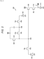
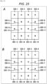
- Fig. 2 is a circuit diagram illustrating the configuration of the unit pixel 100 placed in the pixel array unit 11 in Fig. 1 .
- the unit pixel 100 includes a first opto-electronic converter 101, a first transfer gate unit 102, a second opto-electronic converter 103, a second transfer gate unit 104, a third transfer gate unit 105, a charge accumulation unit 106, a reset gate unit 107, a floating diffusion (FD) unit 108, an amplification transistor 109, and a selection transistor 110.
- a first opto-electronic converter 101 includes a first opto-electronic converter 101, a first transfer gate unit 102, a second opto-electronic converter 103, a second transfer gate unit 104, a third transfer gate unit 105, a charge accumulation unit 106, a reset gate unit 107, a floating diffusion (FD) unit 108, an amplification transistor 109, and a selection transistor 110.
- FD floating diffusion
- the unit pixel 100 is wired with a plurality of drive lines as the pixel drive lines 16 illustrated in Fig. 1 , for example pixel row by pixel row. Then, various drive signals TGL, TGS, FCG, RST, and SEL are supplied via the drive lines from the vertical drive unit 12 illustrated in Fig. 1 . These drive signals are a pulse signal that is in an active state at a high level (for example, the power-supply voltage VDD) and is in a non-active state at a low level (for example, negative potential) because each transistor of the unit pixel 100 is an NMOS transistor.
- a high level for example, the power-supply voltage VDD
- VDD the power-supply voltage
- the first opto-electronic converter 101 includes, for example, a PN-junction photodiode.
- the first opto-electronic converter 101 generates and accumulates charge corresponding to the amount of light that the first opto-electronic converter 101 receives.
- the first transfer gate unit 102 is connected between the first opto-electronic converter 101 and the FD unit 108.
- the drive signal TGL is applied to the gate electrode of the first transfer gate unit 102.
- the first transfer gate unit 102 becomes conductive so that the charge accumulated in the first opto-electronic converter 101 is transferred to the FD unit 108 via the first transfer gate unit 102.
- the second opto-electronic converter 103 includes, for example, a PN-junction photodiode, similarly to the first opto-electronic converter 101.
- the second opto-electronic converter 103 generates and accumulates the charge corresponding to the amount of light that the second opto-electronic converter 103 receives.
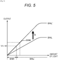
- the unit pixel 100 includes two opto-electronic converters having different sensitivities.
- the first opto-electronic converter 101 works as a high-sensitivity pixel while the second opto-electronic converter 103 works as a low-sensitivity pixel.
- the second transfer gate unit 104 is connected between the charge accumulation unit 106 and the FD unit 108.
- the drive signal FCG is applied to the gate electrode of the second transfer gate unit 104.
- the second transfer gate unit 104 becomes conductive so that the potential well of the charge accumulation unit 106 and the potential well of the FD unit 108 are bound or electrically connected to one another.
- the third transfer gate unit 105 is connected between the second opto-electronic converter 103 and the charge accumulation unit 106.
- the drive signal TGS is applied to the gate electrode of the third transfer gate unit 105.
- the third transfer gate unit 105 becomes conductive so that the charge accumulated in the second opto-electronic converter 103 is transferred via the third transfer gate unit 105 to the charge accumulation unit 106 or a region in which the potential well of the charge accumulation unit 106 and the potential well of the FD unit 108 are bound or electrically connected to one another.
- the potential well is slightly deeper at the lower part of the gate electrode of the third transfer gate unit 105 so as to form an overflow path through which the charge exceeding the amount of charge with which the second opto-electronic converter 103 is saturated and overflowing from the second opto-electronic converter 103 is transferred to the charge accumulation unit 106.
- the overflow path formed on the lower part of the gate electrode of the third transfer gate unit 105 is referred to merely as the overflow path of the third transfer gate unit 105.
- the charge accumulation unit 106 includes, for example, a capacitor, and is connected between the second transfer gate unit 104 and the third transfer gate unit 105.
- the counter electrode of the charge accumulation unit 106 is connected between the charge accumulation unit 106 and the power-supply source VDD that supplies a power-supply voltage VDD.
- the charge accumulation unit 106 accumulates the charge transferred from the second opto-electronic converter 103.
- the reset gate unit 107 is connected between the power-supply source VDD and the FD unit 108.
- the drive signal RST is applied to the gate electrode of the reset gate unit 107.
- the reset gate unit 107 becomes conductive so that the potential of the FD unit 108 is reset into the level of the power-supply voltage VDD.
- the FD unit 108 converts the charge into a voltage signal in charge-voltage conversion and outputs the voltage signal.
- the gate electrode of the amplification transistor 109 is connected to the FD unit 108 while the drain electrode of the amplification transistor 109 is connected to the power-supply source VDD.
- the gate electrode and the drain electrode work as an input unit of the readout circuit that reads the charge retained in the FD unit 108, namely, a so-called source follower circuit.
- the source electrode of the amplification transistor 109 is connected via the selection transistor 110 to the vertical signal line 17, and thus the amplification transistor 109 forms the source follower circuit together with the constant current source 111 connected to a first end of the vertical signal line 17.
- the selection transistor 110 is connected between the source electrode of the amplification transistor 109 and the vertical signal line 17.
- the selection signal SEL is applied to the gate electrode of the selection transistor 110.
- the selection transistor 110 is conductive so that the unit pixel 100 is selected.
- the pixel signal is output from the amplification transistor 109 via the selection transistor 110 to the vertical signal line 17.
- each drive signal is turned into the active state is referred to also as “each drive signal is turned on” and the fact that each drive signal is turned into the non-active state is referred to also as “each drive signal is turned off”.
- each gate unit or each transistor becomes conductive is referred to also as “each gate unit or each transistor is turned on” and the fact that each gate unit or each transistor becomes non-conductive is referred to also as “each gate unit or each transistor is turned off”.
- Fig. 3 illustrates the timing diagram of the horizontal synchronization signal XHS and the drive signals SEL, RST, TGS, FCG, and TGL.
- the horizontal synchronization signal XHS is input and the process for exposure of the unit pixel 100 is started at a time t1.
- the drive signal RST is turned on and the reset gate unit 107 is turned on at a time t2. This resets the potential of the FD unit 108 into the level of the power-supply voltage VDD.
- the drive signals TGL, FCG, and TGS are turned on and the first transfer gate unit 102, the second transfer gate unit 104, and the third transfer gate unit 105 are turned on at a time t3.
- This binds the potential well of the charge accumulation unit 106 with the potential well of the FD unit 108.
- the charge accumulated in the first opto-electronic converter 101 is transferred via the first transfer gate unit 102 to the bound region in which the potential wells are bound.
- the charge accumulated in the second opto-electronic converter 103 transferred via the third transfer gate unit 105 to the bound region. Then, the bound region is reset.
- the drive signals TGL and TGS are turned off and the first transfer gate unit 102 and the third transfer gate unit 105 are turned off at a time t4. This starts the accumulation of the charge into the first opto-electronic converter 101 and the second opto-electronic converter 103 and an exposure period starts.
- the drive signal RST is turned off and the reset gate unit 107 is turned off at a time t5.
- the drive signal FCG is turned off and the second transfer gate unit 104 is turned off at a time t6. This causes the charge accumulation unit 106 to start accumulation of the charge overflowing from the second opto-electronic converter 103 and transferred through the overflow path of the third transfer gate unit 105.
- the horizontal synchronization signal XHS is input at a time t7.
- Fig. 4 illustrates the timing diagram of the horizontal synchronization signal XHS and the drive signals SEL, RST, TGS, FCG, and TGL.
- the horizontal synchronization signal XHS is input and the period of readout of the unit pixel 100 starts at a time t21.
- the selection signal SEL is turned on and the selection transistor 110 is turned on at a time t22. Thus, the unit pixel 100 is selected.
- the drive signal RST is turned on and the reset gate unit 107 is turned on at a time t23.
- the potential of the FD unit 108 is reset into the level of the power-supply voltage VDD.
- the drive signal RST is turned off and the reset gate unit 107 is turned off at a time t24.
- the drive signals FCG and TGS are turned on and the second transfer gate unit 104 and the third transfer gate unit 105 are turned on at a time t25.
- This binds the potential well of the charge accumulation unit 106 and the potential well of the FD unit 108 and transfers the charge accumulated in the second opto-electronic converter 103 to the bound region in which the potential wells are bound.
- the charge accumulated in the second opto-electronic converter 103 and the charge accumulation unit 106 during the exposure period are accumulated in the bound region.
- the readout of the pixel signal is started and the exposure period is completed.
- the drive signal TGS is turned off and the third transfer gate unit 105 is turned off at a time t26. This stops the transfer of the charge from the second opto-electronic converter 103.
- the signal SL based on the potential in the region in which the potential well of the charge accumulation unit 106 and the potential well of the FD unit 108 are bound is output via the amplification transistor 109 and the selection transistor 110 to the vertical signal line 17 at a time ta between the time t26 and the time t27.
- the signal SL is a signal based on the charge generated in the second opto-electronic converter 103 and accumulated in the second opto-electronic converter 103 and the charge accumulation unit 106 during the exposure period.
- the signal SL is a signal based on the potential in the bound region in which the potential well of the charge accumulation unit 106 and the potential well of the FD unit 108 are bound when the charge accumulated in the second opto-electronic converter 103 and the charge accumulation unit 106 during the exposure period is accumulated in the bound region.
- the amount of charge converted in charge-voltage conversion when the signal SL is read is the total amount of charge in the charge accumulation unit 106 and the charge of the FD unit 108.
- the signal SL is referred to also as a low-sensitivity data signal SL hereinafter.
- the drive signal RST is turned on and the reset gate unit 107 is turned on at a time t27. This resets the region in which the potential well of the charge accumulation unit 106 and the potential well of the FD unit 108 are bound.
- the selection signal SEL is turned on and the selection transistor 110 is turned on at a time t30.
- the unit pixel 100 is selected.
- the signal NL is referred to also as a low-sensitivity reset signal NL hereinafter.
- the signal SH based on the potential of the FD unit 108 is output via the amplification transistor 109 and the selection transistor 110 to the vertical signal line 17 at a time td between the time t33 and the time t34.
- the signal SH is a signal based on the charge generated and accumulated in the first opto-electronic converter 101 during the exposure period.
Landscapes
- Engineering & Computer Science (AREA)
- Multimedia (AREA)
- Signal Processing (AREA)
- Transforming Light Signals Into Electric Signals (AREA)
- Solid State Image Pick-Up Elements (AREA)
Applications Claiming Priority (2)
| Application Number | Priority Date | Filing Date | Title |
|---|---|---|---|
| JP2015209533A JP6754157B2 (ja) | 2015-10-26 | 2015-10-26 | 撮像装置 |
| PCT/JP2016/080220 WO2017073322A1 (en) | 2015-10-26 | 2016-10-12 | Image pick-up apparatus |
Publications (2)
| Publication Number | Publication Date |
|---|---|
| EP3369113A1 EP3369113A1 (en) | 2018-09-05 |
| EP3369113B1 true EP3369113B1 (en) | 2025-04-02 |
Family
ID=57227031
Family Applications (1)
| Application Number | Title | Priority Date | Filing Date |
|---|---|---|---|
| EP16790735.1A Active EP3369113B1 (en) | 2015-10-26 | 2016-10-12 | Image pick-up apparatus |
Country Status (6)
| Country | Link |
|---|---|
| US (3) | US10741599B2 (enExample) |
| EP (1) | EP3369113B1 (enExample) |
| JP (1) | JP6754157B2 (enExample) |
| KR (1) | KR102673399B1 (enExample) |
| CN (2) | CN108140661B (enExample) |
| WO (1) | WO2017073322A1 (enExample) |
Families Citing this family (45)
| Publication number | Priority date | Publication date | Assignee | Title |
|---|---|---|---|---|
| JP6754157B2 (ja) * | 2015-10-26 | 2020-09-09 | ソニーセミコンダクタソリューションズ株式会社 | 撮像装置 |
| CN112788225B (zh) | 2016-01-29 | 2023-01-20 | 松下知识产权经营株式会社 | 摄像装置 |
| JP2017163010A (ja) * | 2016-03-10 | 2017-09-14 | ソニー株式会社 | 撮像装置、電子機器 |
| CN108780803B (zh) * | 2016-03-29 | 2023-03-17 | 索尼公司 | 固态成像装置及电子设备 |
| US9954020B1 (en) * | 2016-12-30 | 2018-04-24 | Omnivision Technologies, Inc. | High-dynamic-range color image sensors and associated methods |
| WO2018211813A1 (ja) * | 2017-05-16 | 2018-11-22 | ソニーセミコンダクタソリューションズ株式会社 | 撮像素子、及び、撮像素子を備えた電子機器 |
| JP6974485B2 (ja) * | 2017-09-26 | 2021-12-01 | 富士フイルム株式会社 | 積層体、及び、固体撮像素子 |
| KR102776683B1 (ko) * | 2017-10-03 | 2025-03-07 | 소니 세미컨덕터 솔루션즈 가부시키가이샤 | 고체 촬상 소자, 고체 촬상 소자의 제조 방법 및 전자 기기 |
| WO2019082614A1 (ja) * | 2017-10-27 | 2019-05-02 | ソニーセミコンダクタソリューションズ株式会社 | 撮像装置および撮像方法 |
| US10714517B2 (en) | 2018-01-23 | 2020-07-14 | Samsung Electronics Co., Ltd. | Image sensor |
| US11658193B2 (en) | 2018-01-23 | 2023-05-23 | Samsung Electronics Co., Ltd. | Image sensor |
| JP2019134229A (ja) | 2018-01-29 | 2019-08-08 | ソニーセミコンダクタソリューションズ株式会社 | 撮像素子および撮像装置 |
| JP6779929B2 (ja) | 2018-02-09 | 2020-11-04 | キヤノン株式会社 | 光電変換装置および機器 |
| CN110278396B (zh) | 2018-03-16 | 2024-07-12 | 松下知识产权经营株式会社 | 摄像装置 |
| CN108600660B (zh) * | 2018-05-16 | 2020-06-30 | 上海集成电路研发中心有限公司 | 一种暗电流实时校准的图像传感器及校准方法 |
| JP2021158128A (ja) * | 2018-06-25 | 2021-10-07 | ソニーセミコンダクタソリューションズ株式会社 | 固体撮像装置及び電子機器 |
| WO2020022313A1 (ja) | 2018-07-25 | 2020-01-30 | 株式会社デンソー | 光検出素子およびライダー装置 |
| KR102523851B1 (ko) * | 2018-07-31 | 2023-04-21 | 에스케이하이닉스 주식회사 | 더미 픽셀들을 포함하는 이미지 센싱 장치 |
| JP2022002355A (ja) * | 2018-09-28 | 2022-01-06 | ソニーセミコンダクタソリューションズ株式会社 | 固体撮像素子、固体撮像素子の制御方法および電子機器 |
| US11676980B2 (en) | 2018-10-31 | 2023-06-13 | Taiwan Semiconductor Manufacturing Company, Ltd. | Image sensor and method of making |
| CN112640433B (zh) * | 2019-01-08 | 2024-07-12 | 松下知识产权经营株式会社 | 摄像装置 |
| JP2020136429A (ja) * | 2019-02-18 | 2020-08-31 | ソニーセミコンダクタソリューションズ株式会社 | 撮像素子および撮像装置 |
| US11217613B2 (en) * | 2019-11-18 | 2022-01-04 | Omnivision Technologies, Inc. | Image sensor with split pixel structure and method of manufacturing thereof |
| JP7692840B2 (ja) * | 2019-12-17 | 2025-06-16 | ソニーセミコンダクタソリューションズ株式会社 | 撮像素子、撮像素子の駆動方法および電子機器 |
| US11329086B2 (en) * | 2019-12-27 | 2022-05-10 | Omnivision Technologies, Inc. | Method and structure to improve image sensor crosstalk |
| KR102785979B1 (ko) * | 2020-01-21 | 2025-03-27 | 삼성디스플레이 주식회사 | 표시 패널 |
| US11362121B2 (en) * | 2020-01-28 | 2022-06-14 | Omnivision Technologies, Inc. | Light attenuation layer fabrication method and structure for image sensor |
| US11393861B2 (en) * | 2020-01-30 | 2022-07-19 | Omnivision Technologies, Inc. | Flare-suppressing image sensor |
| US11469264B2 (en) * | 2020-01-30 | 2022-10-11 | Omnivision Technologies, Inc. | Flare-blocking image sensor |
| JP2021175048A (ja) * | 2020-04-22 | 2021-11-01 | ソニーセミコンダクタソリューションズ株式会社 | 電子機器 |
| WO2022019008A1 (ja) * | 2020-07-20 | 2022-01-27 | ソニーセミコンダクタソリューションズ株式会社 | 固体撮像装置及び電子機器 |
| KR102908282B1 (ko) * | 2020-10-16 | 2026-01-08 | 삼성전자주식회사 | 이미지 센서 |
| JP2023182874A (ja) * | 2020-11-13 | 2023-12-27 | ソニーセミコンダクタソリューションズ株式会社 | 固体撮像装置 |
| US11710752B2 (en) * | 2020-12-10 | 2023-07-25 | Omnivision Technologies, Inc. | Flicker-mitigating pixel-array substrate |
| US11670648B2 (en) * | 2020-12-10 | 2023-06-06 | Omnivision Technologies Inc. | Flicker-mitigating pixel-array substrate |
| KR102898632B1 (ko) | 2021-04-09 | 2025-12-09 | 삼성전자주식회사 | 이미지 센서 |
| KR102913462B1 (ko) * | 2021-04-19 | 2026-01-15 | 삼성전자주식회사 | 이미지 센서 |
| CN115604592B (zh) * | 2021-07-08 | 2025-06-06 | 思特威(上海)电子科技股份有限公司 | 图像传感器、制备方法、成像方法及电子设备 |
| CN113764452B (zh) * | 2021-09-06 | 2024-04-26 | 上海集成电路装备材料产业创新中心有限公司 | 像素单元结构及其形成方法 |
| KR20230056409A (ko) * | 2021-10-20 | 2023-04-27 | 삼성전자주식회사 | 이미지 센서 |
| WO2023080197A1 (ja) * | 2021-11-05 | 2023-05-11 | ソニーセミコンダクタソリューションズ株式会社 | 撮像素子、電子機器 |
| US20230352508A1 (en) * | 2022-04-29 | 2023-11-02 | Taiwan Semiconductor Manufacturing Company, Ltd. | Image sensor structure for crosstalk reduction |
| US12426394B2 (en) * | 2022-09-23 | 2025-09-23 | Taiwan Semiconductor Manufacturing Company, Ltd. | CMOS image sensor |
| KR20250009152A (ko) | 2023-07-10 | 2025-01-17 | 삼성전자주식회사 | 이미지 픽셀 및 그것을 포함하는 이미지 센서 장치 |
| CN121420655A (zh) * | 2023-08-08 | 2026-01-27 | 索尼半导体解决方案公司 | 摄像装置 |
Family Cites Families (52)
| Publication number | Priority date | Publication date | Assignee | Title |
|---|---|---|---|---|
| JPH03117284A (ja) * | 1989-09-29 | 1991-05-20 | Canon Inc | 画像再生装置 |
| JPH03117281A (ja) * | 1989-09-29 | 1991-05-20 | Toshiba Corp | 固体撮像装置 |
| JP3071891B2 (ja) | 1991-08-30 | 2000-07-31 | 富士写真フイルム株式会社 | 固体電子撮像装置 |
| JPH05175471A (ja) * | 1991-12-26 | 1993-07-13 | Toshiba Corp | 固体撮像装置 |
| US5590048A (en) * | 1992-06-05 | 1996-12-31 | Fujitsu Limited | Block exposure pattern data extracting system and method for charged particle beam exposure |
| JPH09162381A (ja) * | 1995-12-05 | 1997-06-20 | Sony Corp | リニアセンサ |
| JPH1074926A (ja) * | 1996-08-30 | 1998-03-17 | Sony Corp | 固体撮像素子 |
| JP3071891U (ja) | 2000-03-21 | 2000-09-22 | 株式会社滋賀山下 | ロータリー式流体充填機のパッキン機構 |
| JP4556273B2 (ja) * | 2000-03-21 | 2010-10-06 | ソニー株式会社 | 固体撮像素子およびこれを用いたカメラシステム |
| KR100617024B1 (ko) * | 2000-09-20 | 2006-08-29 | 엘지.필립스 엘시디 주식회사 | 액정표시소자 |
| JP4262446B2 (ja) * | 2002-06-21 | 2009-05-13 | 富士フイルム株式会社 | 固体撮像装置 |
| WO2004027875A1 (ja) * | 2002-09-20 | 2004-04-01 | Sony Corporation | 固体撮像装置及びその製造方法 |
| JP4264251B2 (ja) * | 2002-12-09 | 2009-05-13 | 富士フイルム株式会社 | 固体撮像装置とその動作方法 |
| JP4236168B2 (ja) * | 2003-09-10 | 2009-03-11 | 富士フイルム株式会社 | 固体撮像装置 |
| JP4236169B2 (ja) * | 2003-09-10 | 2009-03-11 | 富士フイルム株式会社 | 固体撮像装置 |
| JP2005116568A (ja) * | 2003-10-02 | 2005-04-28 | Sony Corp | 固体撮像素子 |
| JP4317115B2 (ja) | 2004-04-12 | 2009-08-19 | 国立大学法人東北大学 | 固体撮像装置、光センサおよび固体撮像装置の動作方法 |
| JP2006253876A (ja) | 2005-03-09 | 2006-09-21 | Sony Corp | 物理量分布検知装置および物理量分布検知装置の駆動方法 |
| JP2007135200A (ja) * | 2005-10-14 | 2007-05-31 | Sony Corp | 撮像方法および撮像装置並びに駆動装置 |
| US7964840B2 (en) * | 2008-06-19 | 2011-06-21 | Omnivision Technologies, Inc. | High dynamic range image sensor including polarizer and microlens |
| JP5396809B2 (ja) * | 2008-10-17 | 2014-01-22 | ソニー株式会社 | 固体撮像装置、カメラ、および、固体撮像装置の製造方法 |
| JP5521312B2 (ja) * | 2008-10-31 | 2014-06-11 | ソニー株式会社 | 固体撮像装置及びその製造方法、並びに電子機器 |
| JP5428509B2 (ja) * | 2009-05-11 | 2014-02-26 | ソニー株式会社 | 2次元固体撮像装置、及び、2次元固体撮像装置における偏光光データ処理方法 |
| CN102097076A (zh) * | 2009-12-10 | 2011-06-15 | 索尼公司 | 显示设备 |
| US20110175981A1 (en) * | 2010-01-19 | 2011-07-21 | Chun-Hung Lai | 3d color image sensor |
| JP5091964B2 (ja) * | 2010-03-05 | 2012-12-05 | 株式会社東芝 | 固体撮像装置 |
| JP5025746B2 (ja) * | 2010-03-19 | 2012-09-12 | 株式会社東芝 | 固体撮像装置 |
| JP2011215352A (ja) * | 2010-03-31 | 2011-10-27 | Sony Corp | 光学シート積層体、照明装置および表示装置 |
| JP2012009539A (ja) * | 2010-06-23 | 2012-01-12 | Sony Corp | 固体撮像装置、電子機器、固体撮像装置の製造方法 |
| CN102156367B (zh) * | 2010-08-04 | 2013-06-19 | 京东方科技集团股份有限公司 | 阵列基板、液晶面板和液晶显示器 |
| JP5682174B2 (ja) * | 2010-08-09 | 2015-03-11 | ソニー株式会社 | 固体撮像装置とその製造方法、並びに電子機器 |
| JP5637384B2 (ja) * | 2010-12-15 | 2014-12-10 | ソニー株式会社 | 固体撮像素子および駆動方法、並びに電子機器 |
| KR20120080845A (ko) * | 2011-01-10 | 2012-07-18 | 삼성전자주식회사 | 광 감지 기능을 구비한 oled 디스플레이 장치 |
| JP5810551B2 (ja) * | 2011-02-25 | 2015-11-11 | ソニー株式会社 | 固体撮像装置、および、その製造方法、電子機器 |
| JP6299058B2 (ja) * | 2011-03-02 | 2018-03-28 | ソニー株式会社 | 固体撮像装置、固体撮像装置の製造方法及び電子機器 |
| JP2012226161A (ja) * | 2011-04-20 | 2012-11-15 | Sony Corp | 表示装置 |
| JP5353965B2 (ja) * | 2011-07-11 | 2013-11-27 | ソニー株式会社 | 固体撮像装置の製造方法 |
| JP5794068B2 (ja) * | 2011-09-16 | 2015-10-14 | ソニー株式会社 | 固体撮像素子および製造方法、並びに電子機器 |
| JP2014086552A (ja) * | 2012-10-23 | 2014-05-12 | Sharp Corp | 固体撮像素子及び固体撮像素子の製造方法 |
| JP2014175553A (ja) * | 2013-03-11 | 2014-09-22 | Canon Inc | 固体撮像装置およびカメラ |
| US20140339606A1 (en) * | 2013-05-16 | 2014-11-20 | Visera Technologies Company Limited | Bsi cmos image sensor |
| JP6130221B2 (ja) * | 2013-05-24 | 2017-05-17 | ソニー株式会社 | 固体撮像装置、および電子機器 |
| JP2015012127A (ja) | 2013-06-28 | 2015-01-19 | ソニー株式会社 | 固体撮像素子および電子機器 |
| JP6480862B2 (ja) | 2013-07-22 | 2019-03-13 | ソニーセミコンダクタソリューションズ株式会社 | 固体撮像素子および電子機器 |
| WO2015015722A1 (ja) | 2013-07-29 | 2015-02-05 | パナソニックIpマネジメント株式会社 | 光学フィルタおよびそれを用いた偏光撮像装置 |
| JP2015065270A (ja) * | 2013-09-25 | 2015-04-09 | ソニー株式会社 | 固体撮像装置およびその製造方法、並びに電子機器 |
| JP2015095879A (ja) * | 2013-11-14 | 2015-05-18 | 株式会社リコー | 撮像装置及び偏光フィルタ |
| JP2015153859A (ja) * | 2014-02-13 | 2015-08-24 | 株式会社東芝 | 固体撮像装置 |
| KR102367384B1 (ko) * | 2015-01-13 | 2022-02-25 | 삼성전자주식회사 | 이미지 센서 및 그 형성 방법 |
| JP6668036B2 (ja) * | 2015-10-14 | 2020-03-18 | ソニーセミコンダクタソリューションズ株式会社 | 撮像素子及びその製造方法、並びに、撮像装置及びその製造方法 |
| JP6754157B2 (ja) * | 2015-10-26 | 2020-09-09 | ソニーセミコンダクタソリューションズ株式会社 | 撮像装置 |
| US10818718B2 (en) * | 2016-07-20 | 2020-10-27 | Sony Corporation | Light receiving element, method of manufacturing light receiving element, imaging device, and electronic apparatus |
-
2015
- 2015-10-26 JP JP2015209533A patent/JP6754157B2/ja active Active
-
2016
- 2016-10-12 KR KR1020187010717A patent/KR102673399B1/ko active Active
- 2016-10-12 US US15/768,378 patent/US10741599B2/en active Active
- 2016-10-12 EP EP16790735.1A patent/EP3369113B1/en active Active
- 2016-10-12 CN CN201680060810.3A patent/CN108140661B/zh active Active
- 2016-10-12 WO PCT/JP2016/080220 patent/WO2017073322A1/en not_active Ceased
- 2016-10-12 CN CN202211225689.9A patent/CN115472639B/zh active Active
-
2020
- 2020-07-08 US US16/924,010 patent/US11271026B2/en active Active
-
2022
- 2022-01-12 US US17/574,033 patent/US20220216249A1/en active Pending
Non-Patent Citations (1)
| Title |
|---|
| G. HASS ET AL: "Optical Constants and Reflectance and Transmittance of Evaporated Aluminum in the Visible and Ultraviolet", JOURNAL OF THE OPTICAL SOCIETY OF AMERICA, vol. 51, no. 7, 1 July 1961 (1961-07-01), pages 719, XP055036880, ISSN: 0030-3941, DOI: 10.1364/JOSA.51.000719 * |
Also Published As
| Publication number | Publication date |
|---|---|
| EP3369113A1 (en) | 2018-09-05 |
| US20220216249A1 (en) | 2022-07-07 |
| US11271026B2 (en) | 2022-03-08 |
| CN108140661A (zh) | 2018-06-08 |
| WO2017073322A1 (en) | 2017-05-04 |
| CN115472639B (zh) | 2025-12-16 |
| US10741599B2 (en) | 2020-08-11 |
| CN115472639A (zh) | 2022-12-13 |
| CN108140661B (zh) | 2022-10-18 |
| KR20180075497A (ko) | 2018-07-04 |
| KR102673399B1 (ko) | 2024-06-10 |
| US20180308883A1 (en) | 2018-10-25 |
| JP2017084892A (ja) | 2017-05-18 |
| US20200335537A1 (en) | 2020-10-22 |
| JP6754157B2 (ja) | 2020-09-09 |
Similar Documents
| Publication | Publication Date | Title |
|---|---|---|
| EP3369113B1 (en) | Image pick-up apparatus | |
| US12495628B2 (en) | Imaging device including photoelectric converters and capacitor | |
| EP2654081B1 (en) | Solid state imaging device, driving method of the solid state imaging device, and electronic equipment | |
| EP2253017B1 (en) | Circuit and photo sensor overlap for backside illumination image sensor | |
| US8785834B2 (en) | Solid-state image sensor, control method for the same, and electronic device | |
| US10784304B2 (en) | Solid-state imaging apparatus, and electronic apparatus | |
| CN104917942B (zh) | 图像捕获装置和图像捕获系统 | |
| US11463645B2 (en) | Solid-state imaging element and electronic device including a shared structure for pixels for sharing an AD converter | |
| JP2020141146A (ja) | 撮像装置 | |
| US9385154B2 (en) | Solid-state image sensor, driving method and electronic apparatus | |
| JPWO2020054162A1 (ja) | 撮像装置および撮像方法 | |
| JP2014183064A (ja) | 固体撮像素子および製造方法、並びに電子機器 | |
| CN104159050A (zh) | 固态图像传感器、驱动固态图像传感器的方法及电子设备 | |
| JPWO2020054373A1 (ja) | 撮像装置および撮像方法 |
Legal Events
| Date | Code | Title | Description |
|---|---|---|---|
| STAA | Information on the status of an ep patent application or granted ep patent |
Free format text: STATUS: UNKNOWN |
|
| STAA | Information on the status of an ep patent application or granted ep patent |
Free format text: STATUS: THE INTERNATIONAL PUBLICATION HAS BEEN MADE |
|
| PUAI | Public reference made under article 153(3) epc to a published international application that has entered the european phase |
Free format text: ORIGINAL CODE: 0009012 |
|
| STAA | Information on the status of an ep patent application or granted ep patent |
Free format text: STATUS: REQUEST FOR EXAMINATION WAS MADE |
|
| 17P | Request for examination filed |
Effective date: 20180522 |
|
| AK | Designated contracting states |
Kind code of ref document: A1 Designated state(s): AL AT BE BG CH CY CZ DE DK EE ES FI FR GB GR HR HU IE IS IT LI LT LU LV MC MK MT NL NO PL PT RO RS SE SI SK SM TR |
|
| AX | Request for extension of the european patent |
Extension state: BA ME |
|
| DAV | Request for validation of the european patent (deleted) | ||
| DAX | Request for extension of the european patent (deleted) | ||
| STAA | Information on the status of an ep patent application or granted ep patent |
Free format text: STATUS: EXAMINATION IS IN PROGRESS |
|
| 17Q | First examination report despatched |
Effective date: 20210322 |
|
| GRAP | Despatch of communication of intention to grant a patent |
Free format text: ORIGINAL CODE: EPIDOSNIGR1 |
|
| STAA | Information on the status of an ep patent application or granted ep patent |
Free format text: STATUS: GRANT OF PATENT IS INTENDED |
|
| INTG | Intention to grant announced |
Effective date: 20241028 |
|
| GRAS | Grant fee paid |
Free format text: ORIGINAL CODE: EPIDOSNIGR3 |
|
| GRAA | (expected) grant |
Free format text: ORIGINAL CODE: 0009210 |
|
| STAA | Information on the status of an ep patent application or granted ep patent |
Free format text: STATUS: THE PATENT HAS BEEN GRANTED |
|
| P01 | Opt-out of the competence of the unified patent court (upc) registered |
Free format text: CASE NUMBER: APP_6758/2025 Effective date: 20250210 |
|
| AK | Designated contracting states |
Kind code of ref document: B1 Designated state(s): AL AT BE BG CH CY CZ DE DK EE ES FI FR GB GR HR HU IE IS IT LI LT LU LV MC MK MT NL NO PL PT RO RS SE SI SK SM TR |
|
| REG | Reference to a national code |
Ref country code: GB Ref legal event code: FG4D |
|
| REG | Reference to a national code |
Ref country code: IE Ref legal event code: FG4D |
|
| REG | Reference to a national code |
Ref country code: DE Ref legal event code: R096 Ref document number: 602016091775 Country of ref document: DE |
|
| REG | Reference to a national code |
Ref country code: NL Ref legal event code: MP Effective date: 20250402 |
|
| PG25 | Lapsed in a contracting state [announced via postgrant information from national office to epo] |
Ref country code: NL Free format text: LAPSE BECAUSE OF FAILURE TO SUBMIT A TRANSLATION OF THE DESCRIPTION OR TO PAY THE FEE WITHIN THE PRESCRIBED TIME-LIMIT Effective date: 20250402 |
|
| REG | Reference to a national code |
Ref country code: AT Ref legal event code: MK05 Ref document number: 1782188 Country of ref document: AT Kind code of ref document: T Effective date: 20250402 |
|
| PG25 | Lapsed in a contracting state [announced via postgrant information from national office to epo] |
Ref country code: ES Free format text: LAPSE BECAUSE OF FAILURE TO SUBMIT A TRANSLATION OF THE DESCRIPTION OR TO PAY THE FEE WITHIN THE PRESCRIBED TIME-LIMIT Effective date: 20250402 Ref country code: PT Free format text: LAPSE BECAUSE OF FAILURE TO SUBMIT A TRANSLATION OF THE DESCRIPTION OR TO PAY THE FEE WITHIN THE PRESCRIBED TIME-LIMIT Effective date: 20250804 Ref country code: FI Free format text: LAPSE BECAUSE OF FAILURE TO SUBMIT A TRANSLATION OF THE DESCRIPTION OR TO PAY THE FEE WITHIN THE PRESCRIBED TIME-LIMIT Effective date: 20250402 |
|
| REG | Reference to a national code |
Ref country code: LT Ref legal event code: MG9D |
|
| PG25 | Lapsed in a contracting state [announced via postgrant information from national office to epo] |
Ref country code: GR Free format text: LAPSE BECAUSE OF FAILURE TO SUBMIT A TRANSLATION OF THE DESCRIPTION OR TO PAY THE FEE WITHIN THE PRESCRIBED TIME-LIMIT Effective date: 20250703 Ref country code: NO Free format text: LAPSE BECAUSE OF FAILURE TO SUBMIT A TRANSLATION OF THE DESCRIPTION OR TO PAY THE FEE WITHIN THE PRESCRIBED TIME-LIMIT Effective date: 20250702 |
|
| PG25 | Lapsed in a contracting state [announced via postgrant information from national office to epo] |
Ref country code: PL Free format text: LAPSE BECAUSE OF FAILURE TO SUBMIT A TRANSLATION OF THE DESCRIPTION OR TO PAY THE FEE WITHIN THE PRESCRIBED TIME-LIMIT Effective date: 20250402 |
|
| PG25 | Lapsed in a contracting state [announced via postgrant information from national office to epo] |
Ref country code: BG Free format text: LAPSE BECAUSE OF FAILURE TO SUBMIT A TRANSLATION OF THE DESCRIPTION OR TO PAY THE FEE WITHIN THE PRESCRIBED TIME-LIMIT Effective date: 20250402 |
|
| PG25 | Lapsed in a contracting state [announced via postgrant information from national office to epo] |
Ref country code: HR Free format text: LAPSE BECAUSE OF FAILURE TO SUBMIT A TRANSLATION OF THE DESCRIPTION OR TO PAY THE FEE WITHIN THE PRESCRIBED TIME-LIMIT Effective date: 20250402 |
|
| PG25 | Lapsed in a contracting state [announced via postgrant information from national office to epo] |
Ref country code: AT Free format text: LAPSE BECAUSE OF FAILURE TO SUBMIT A TRANSLATION OF THE DESCRIPTION OR TO PAY THE FEE WITHIN THE PRESCRIBED TIME-LIMIT Effective date: 20250402 |
|
| PG25 | Lapsed in a contracting state [announced via postgrant information from national office to epo] |
Ref country code: RS Free format text: LAPSE BECAUSE OF FAILURE TO SUBMIT A TRANSLATION OF THE DESCRIPTION OR TO PAY THE FEE WITHIN THE PRESCRIBED TIME-LIMIT Effective date: 20250702 |
|
| PG25 | Lapsed in a contracting state [announced via postgrant information from national office to epo] |
Ref country code: IS Free format text: LAPSE BECAUSE OF FAILURE TO SUBMIT A TRANSLATION OF THE DESCRIPTION OR TO PAY THE FEE WITHIN THE PRESCRIBED TIME-LIMIT Effective date: 20250802 |
|
| PG25 | Lapsed in a contracting state [announced via postgrant information from national office to epo] |
Ref country code: LV Free format text: LAPSE BECAUSE OF FAILURE TO SUBMIT A TRANSLATION OF THE DESCRIPTION OR TO PAY THE FEE WITHIN THE PRESCRIBED TIME-LIMIT Effective date: 20250402 |
|
| REG | Reference to a national code |
Ref country code: DE Ref legal event code: R097 Ref document number: 602016091775 Country of ref document: DE |
|
| PG25 | Lapsed in a contracting state [announced via postgrant information from national office to epo] |
Ref country code: SM Free format text: LAPSE BECAUSE OF FAILURE TO SUBMIT A TRANSLATION OF THE DESCRIPTION OR TO PAY THE FEE WITHIN THE PRESCRIBED TIME-LIMIT Effective date: 20250402 Ref country code: DK Free format text: LAPSE BECAUSE OF FAILURE TO SUBMIT A TRANSLATION OF THE DESCRIPTION OR TO PAY THE FEE WITHIN THE PRESCRIBED TIME-LIMIT Effective date: 20250402 |
|
| PG25 | Lapsed in a contracting state [announced via postgrant information from national office to epo] |
Ref country code: CZ Free format text: LAPSE BECAUSE OF FAILURE TO SUBMIT A TRANSLATION OF THE DESCRIPTION OR TO PAY THE FEE WITHIN THE PRESCRIBED TIME-LIMIT Effective date: 20250402 |
|
| PG25 | Lapsed in a contracting state [announced via postgrant information from national office to epo] |
Ref country code: EE Free format text: LAPSE BECAUSE OF FAILURE TO SUBMIT A TRANSLATION OF THE DESCRIPTION OR TO PAY THE FEE WITHIN THE PRESCRIBED TIME-LIMIT Effective date: 20250402 |
|
| PG25 | Lapsed in a contracting state [announced via postgrant information from national office to epo] |
Ref country code: SK Free format text: LAPSE BECAUSE OF FAILURE TO SUBMIT A TRANSLATION OF THE DESCRIPTION OR TO PAY THE FEE WITHIN THE PRESCRIBED TIME-LIMIT Effective date: 20250402 Ref country code: RO Free format text: LAPSE BECAUSE OF FAILURE TO SUBMIT A TRANSLATION OF THE DESCRIPTION OR TO PAY THE FEE WITHIN THE PRESCRIBED TIME-LIMIT Effective date: 20250402 |
|
| PG25 | Lapsed in a contracting state [announced via postgrant information from national office to epo] |
Ref country code: IT Free format text: LAPSE BECAUSE OF FAILURE TO SUBMIT A TRANSLATION OF THE DESCRIPTION OR TO PAY THE FEE WITHIN THE PRESCRIBED TIME-LIMIT Effective date: 20250402 |
|
| PLBE | No opposition filed within time limit |
Free format text: ORIGINAL CODE: 0009261 |
|
| STAA | Information on the status of an ep patent application or granted ep patent |
Free format text: STATUS: NO OPPOSITION FILED WITHIN TIME LIMIT |
|
| REG | Reference to a national code |
Ref country code: CH Ref legal event code: L10 Free format text: ST27 STATUS EVENT CODE: U-0-0-L10-L00 (AS PROVIDED BY THE NATIONAL OFFICE) Effective date: 20260211 |
|
| 26N | No opposition filed |
Effective date: 20260105 |