EP3368438B1 - Extrusionsblasgeformter behälter - Google Patents
Extrusionsblasgeformter behälter Download PDFInfo
- Publication number
- EP3368438B1 EP3368438B1 EP16790920.9A EP16790920A EP3368438B1 EP 3368438 B1 EP3368438 B1 EP 3368438B1 EP 16790920 A EP16790920 A EP 16790920A EP 3368438 B1 EP3368438 B1 EP 3368438B1
- Authority
- EP
- European Patent Office
- Prior art keywords
- container
- container according
- sealing surfaces
- sealing surface
- section
- Prior art date
- Legal status (The legal status is an assumption and is not a legal conclusion. Google has not performed a legal analysis and makes no representation as to the accuracy of the status listed.)
- Active
Links
Images

Classifications
-
- B—PERFORMING OPERATIONS; TRANSPORTING
- B65—CONVEYING; PACKING; STORING; HANDLING THIN OR FILAMENTARY MATERIAL
- B65D—CONTAINERS FOR STORAGE OR TRANSPORT OF ARTICLES OR MATERIALS, e.g. BAGS, BARRELS, BOTTLES, BOXES, CANS, CARTONS, CRATES, DRUMS, JARS, TANKS, HOPPERS, FORWARDING CONTAINERS; ACCESSORIES, CLOSURES, OR FITTINGS THEREFOR; PACKAGING ELEMENTS; PACKAGES
- B65D35/00—Pliable tubular containers adapted to be permanently or temporarily deformed to expel contents, e.g. collapsible tubes for toothpaste or other plastic or semi-liquid material; Holders therefor
- B65D35/24—Pliable tubular containers adapted to be permanently or temporarily deformed to expel contents, e.g. collapsible tubes for toothpaste or other plastic or semi-liquid material; Holders therefor with auxiliary devices
-
- B—PERFORMING OPERATIONS; TRANSPORTING
- B65—CONVEYING; PACKING; STORING; HANDLING THIN OR FILAMENTARY MATERIAL
- B65D—CONTAINERS FOR STORAGE OR TRANSPORT OF ARTICLES OR MATERIALS, e.g. BAGS, BARRELS, BOTTLES, BOXES, CANS, CARTONS, CRATES, DRUMS, JARS, TANKS, HOPPERS, FORWARDING CONTAINERS; ACCESSORIES, CLOSURES, OR FITTINGS THEREFOR; PACKAGING ELEMENTS; PACKAGES
- B65D2205/00—Venting means
Definitions
- the invention relates to a container made from a plastic material by extrusion blow molding according to the preamble of claim 1.
- plastic containers in particular plastic bottles, for example made of polyethylene or polypropylene
- Plastic suitable for blow molding is plasticized using an extruder and introduced into a hose head.
- the plastic is formed into a hose, which is inserted into a blow molding tool.
- the hose is introduced into the blow molding tool and is inflated with the tool closed via a blow mandrel using excess pressure of a gas, so that the hose expands and is pressed against an inner wall of a cavity of the blow molding tool and takes on the shape of the inner wall, which has the negative shape of a container .
- the inner wall is used to cool the container blown from the tube until the plastic has hardened.
- the container is then removed from the opened blow molding tool.
- the so-called slugs which form due to the hose protruding when the blow mold is closed and are usually connected to the removed container, are separated and can be fed into the recycling stream.
- the hose can be single-layer or multi-layer.
- the outlet openings are formed at one end of the container during blow molding. Accordingly, the containers are filled via the outlet opening during the filling process.
- the filling speed on the filling line therefore depends on the cross section of the outlet opening and the consistency of the product to be filled.
- the US 5,013,517 discloses a blow molded container.
- the container has an upper, non-intrinsically stable area, at the upper end of which a pressure closure is formed during blow molding.
- At the bottom of the top area is connected to a lower area of the container, which has a greater wall thickness than the upper area and is therefore inherently stable.
- the lower area of the container is closed by a bottom.
- the upper end of the container on which the pressure closure is formed can be flattened, whereby the two ends of the pressure closure can be brought into positive engagement with one another. This means that the upper end of the container can be re-closed using the pressure closure.
- a flexible container which is made from a film.
- a first and a second side wall and a bottom wall which walls are cut out of the film, are welded or glued together at their edges.
- the container can also be folded from a single sheet of foil. The first and second walls and the bottom wall are sealed together at the folded edges.
- the two flaps After inserting the object into the receiving space through the opening, the two flaps are connected to one another on their upper long sides. This partially closes the opening.
- the packaging is open in the area of the cut triangular parts.
- the object can be presented in the packaging in a sales room by providing openings on the flaps from which the packaging and the solid object can be hung.
- EP 2 910 486 A1 describes a foil bag whose body is rolled out of foil. By providing a longitudinal seam, a cylinder is formed from the film. The lower end of the cylinder is closed with an inner part and an outer part made of foil, forming a stand-up pouch.
- a container made from a plastic material by extrusion blow molding which has a container body with a first end and a second end substantially opposite the first end.
- the first end has on its inner wall a first sealing surface and a second sealing surface substantially opposite the first sealing surface, wherein the first and second sealing surfaces can be connected to one another in a fluid-tight manner.
- the second end is sealed in a fluid-tight manner and is designed as a container base with a standing surface.
- the container is designed as an extrusion bias-formed cup, at the first end of which, namely the open end, the filling material can be filled between the sealing surfaces at high speed.
- the air to be displaced by the filling material during filling into the extrusion blow molded container can escape over the entire cross-sectional area of the container and accordingly does not lead to an impairment of the filling, as can be the case with containers according to the prior art, especially with small openings. Because the air can escape essentially pressure-free, there is generally no foam formation in the filling material to be filled while the container is being filled.
- the container After the container has been filled, it can be closed in a fluid-tight manner by means of the sealing surfaces formed on the inner wall. Closing can be done by gluing or preferably by welding.
- the sealing surfaces are preferably formed by a weldable or adhesive material.
- the container with the filled product can be made by heating and pressing the opposite sealing surfaces, as can be done, for example, by welding bars.
- the sealing surfaces can only be partially provided in the joining area with coatings such as an adhesion promoter or a hot melt adhesive, for example by spraying, rolling or can be applied as tape.
- adhesion promoters and hot melt adhesives have a lower melting point than the plastic of the preform from which the container is made.
- the adhesion promoters or hot melt adhesive can also be textured.
- the bonding agent or hot melt adhesive can also be used to connect inserts to the container that would not be connected to the container by welding.
- An insert element can be, for example, a film with a pass-through opening or a closure part.
- the insert element can also extend over the entire length of the sealing surface.
- the sealing surface is to be understood as the welding or adhesive surface, which, as explained above, can also have coatings.
- the container itself can be designed with one layer or multiple layers, so that barrier layers such as EVOH or PA can also be formed in the container.
- the container body is stable and stabilization by appropriate devices during transport through the filling line is not necessary.
- the design of the base which is inherently stable thanks to its extrusion-blow molding, also makes a decisive contribution to this.
- the cross section of the container is essentially unlimited with regard to its geometric design.
- the cross-section of the container will be round, oval, elliptical or rectangular.
- the cross-sectional shape can also change over the longitudinal extent of the container.
- the base can be square and the first end can be circular. Due to the high inherent stability of the container, it can be decorated before or after filling, for example by printing or sticking on labels or so-called sleeves. Since the container is extrusion blow molded, a decoration that is raised or recessed relative to the adjacent wall of the container body can also be formed, which can also consist of lettering, for example. Decoration can also be applied to the blow mold cavity in its cavity by in-mold labeling during extrusion blow molding.
- the standing surface on the bottom of the container can be designed all around or in the form of feet that are spaced apart from one another.
- the bottom of the container does not have an opening that can be used to fill or empty contents.
- the fluid-tight connection can be made by gluing or welding. If the container is glued, the adhesive can be supplied from the outside or already applied to the inside of the sealing surfaces. Bonding or welding can be done by applying heat. For UV-permeable material, bonding can also be done using UV-curing adhesives. As a rule, an inseparable, fluid-tight connection between the sealing surfaces is created.
- the wall thickness of the first portion of the container body adjacent to the container base can be thicker than a second portion adjacent to the first portion, which can extend to the first end.
- the container body can taper continuously from the container bottom to the second edge.
- an acute angle is enclosed between a wall of the container body and a central axis of the container such that an area enclosed by the inner wall at the first end is larger than an area enclosed by the inner wall at the second end.
- the containers can be stacked one inside the other and can be stored in a space-saving manner and/or transported to the filling line.
- the angle enclosed between a wall of the container body and a central axis of the container is greater than or equal to 0.5° and equal to or less than 30°, preferably equal to or less than 15° and particularly preferably equal to or less than 7.5 °.
- the angle will be chosen so that the containers stacked one inside the other can be easily removed from the stack individually without any additional aids.
- the angle will be chosen so large that self-locking is effectively avoided.
- a closure element with an outlet opening is arranged between the sealing surfaces and is connected in a fluid-tight manner to the first sealing surface and the second sealing surface.
- the closure element is held simply and reliably between the first and second sealing surfaces, since it is welded or glued to the sealing surfaces, which must be connected to one another in a fluid-tight manner after the container has been filled with the contents.
- An adhesive process can be used to connect partners who are not capable of welding to one another.
- a container made of HDPE can be permanently connected in a fluid-tight manner to a closure element made of PP, and vice versa.
- the adhesive layer can also be applied exclusively to the closure element if it is adapted to the opening of the container. The fluid-tight connection of the sealing surfaces to one another and the fluid-tight connection of the closure element to the sealing surfaces can thus take place in one operation.
- sealing surfaces and a closure element arranged between them is particularly advantageous since this allows the closure element to have complex shapes that do not have to be formed during extrusion blow molding. Rather, the closure element is arranged between the sealing surfaces after extrusion blow molding.
- the blow mold for producing the container according to the present invention can therefore be designed to be simpler than blow molds in which the shape of the closure element is blow molded. In many cases, shapes of the closure element cannot be formed using extrusion blow molding.
- the container can therefore be produced in a blow mold without a formation for an outlet opening being provided in the blow mold would have to.
- the closure element can be produced in a wide variety of manufacturing processes, for example injection molding, since it is independent of the extrusion blow molding of the container. It goes without saying that, if necessary, more than one closure element can be arranged between the sealing surfaces.
- the closure element has a neck.
- the outlet opening extends through the closure element and the neck.
- the contents can therefore be removed through the neck and are at a sufficient distance from the container body.
- the neck can be designed at its free end in such a way that liquid container contents can be removed without dripping.
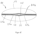
- the closure element has a middle part and at least one end part, the middle part tapering towards the at least one end part, whereby it has a streamlined shape.
- the streamlined shape in particular makes it possible for the sealing surfaces to come into contact with the closure element at every point and for there to be no leaks between the sealing surfaces and the closure element.
- the end part will usually be pointed, while the middle part will be curved. This means that the end part can smoothly merge into a fold that is formed by the sealing surfaces connected to one another.
- the middle part can be curved, preferably evenly curved.
- the middle part can also form a corner of the fold, in which case this corner can then not be pointed but can be designed as a round corner.
- the middle part will be formed essentially as a straight circular cylinder transversely to the longitudinal direction of the fold, so that the streamlined shape is essentially formed by a two-dimensional curved surface which extends in the longitudinal direction of the fold.
- Two end parts can also be arranged on the middle part. The two end parts are then usually opposite each other, but can also enclose an angle that is smaller than 180° and larger than 0°.
- At least one welding rib is formed on the closure element at least partially along a longitudinal extent of the sealing surfaces.
- the welding rib which is designed as an elevation on the closure element extending in the direction of at least one of the sealing surfaces, will be formed both on the side facing the first sealing surface and on the side of the holding insert facing the second sealing surface.
- the welding rib reduces the amount of heat to be applied for welding, so that overall less heat is introduced into the container.
- More than one welding rib can be arranged on one side of the closure element, the welding ribs generally having the same shape and being spaced apart from one another. Providing more than one welding rib can ensure that the occurrence of leaky welds between sealing surfaces and the closure element is minimized. If one welding rib has a leak, the other welding rib is most likely tight. In order to increase security, more than two welding ribs can also be provided on the closure element.
- the sealing surfaces extend along the first end.
- the first end after being extrusion blow molded, has a fill opening which is delimited by the first and second sealing surfaces.
- the filling opening of the claimed container is only limited by its width. The filling process can therefore be simplified and accelerated by the enlarged filling opening.
- the first end is continuously designed as a first and second sealing surface.
- the filling opening has the maximum size and is limited at the edge by the container body. Sealing surfaces that do not extend to the wall of the container body are also conceivable. Depending on the application of the container, sealing surfaces of any length and shape can be formed in the blow mold.
- the sealing surfaces each have a first and second section, with the closure element being arranged in the first section.
- the first and second sections can have different sealing lengths, sealing surfaces with different surfaces and different angles to one another. This means that the first section and the second section can be used for different applications. For example, the first section can be used to hold the closure element and the second section can be used to form a handle. become.
- the first section and the second section expediently enclose an angle that is greater than 0° and less than or equal to 180°.
- the second section is designed like a film and has a pass-through opening.
- a handle By punching out a pass-through surface in the second film-like section, a handle can be easily formed.
- a handle By choosing the size of the surface of the second section, a handle can be formed which is adapted to the weight of the filled container and does not tear out.
- the second section will be formed in that the two sealing surfaces are connected to one another in a fluid-tight manner over the entire surface.
- the sealing surfaces of the second section can also only be partially connected to one another in a fluid-tight manner, for example all around the access opening and for demarcation, so that the container contents cannot reach the environment except through the outlet opening.
- the second end of the container is designed as a standing surface.
- the container has a stable stand due to the provision of the standing surface.
- the standing surface causes a stable stand despite the reduced weight of the container.
- the formation of the standing surface during extrusion blow molding enables the formation of a standing surface without protrusions.
- the container has a standing surface, the entire surface of which rests on the ground.
- the container is formed from an extrusion blow-molded hollow body that is open at the first end, which can be filled through the first end and whose first end can be closed by the fluid-tight connection of the sealing surfaces.
- the hollow body has a base and an adjoining wall and can be manufactured in a relatively simple blow mold.
- the filling opening is only reduced in size after filling with the product. Since the closure element can only be arranged between the sealing surfaces after the extrusion blow molding process or even after filling, its shape is decoupled from the extrusion blow molding.
- the closure element can therefore have any shape that does not influence the extrusion blow molding process.
- An extrusion blow molded handle is expediently formed on the container body.
- the ratio of a maximum thickness of the middle part, which extends between the first sealing surface and the second sealing surface, to a length of the closure element, which extends along the sealing surfaces is between 1:1 and 1:10 and is preferred between 1:2 and 1:4.
- the curvature of the holding insert is not too pronounced, which means that the sealing surfaces can rest against the holding insert over the entire surface.
- the closure element is advantageously made of a material which can be connected in a fluid-tight manner to the material of the sealing surfaces.
- the holding insert and the sealing surfaces are made of plastic. Because the plastics of the sealing surfaces and the holding insert flow into one another during welding, their connection is usually permanently tight.
- the closure element has fastening means on its neck, which can be brought into engagement with corresponding fastening means of a closure cap in such a way that the outlet opening can be closed in a fluid-tight manner.
- the fastening means can be bayonets, threads, thread segments, projections or recesses with which closure caps such as bayonet closures, screw closures or snap closures can be attached to the neck to prevent wear on the outlet opening.
- closure caps such as bayonet closures, screw closures or snap closures can be attached to the neck to prevent wear on the outlet opening.
- the closure can also be firmly connected to the closure element, or neck, and thus be captive.
- the fastening means are at least sections of at least one thread that corresponds to one another, so that the closure cap can be repeatedly screwed onto the neck and/or unscrewed from the neck.
- the container is formed in one piece.
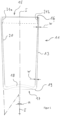
- Fig. 1 shows a proposed container 11 produced using the extrusion blow molding process, which has a container body 13, the container body 13 has a first end 15 and a second end 17 which is essentially opposite the first end 15.
- the second end 17 is closed in a fluid-tight manner and is designed as a container base 18, on which a standing surface 19 is formed.
- the extrusion-blow-molded container 11 has an inner wall 20.
- the inner wall 20 delimits a filling opening 16 at the first end 15, through which a filling material is filled into the extrusion-blow-molded container 11.
- the first end 15 has on its inner wall 20 a first sealing surface 21a and a second sealing surface 21b opposite the first sealing surface 21a, which can be connected to one another in a fluid-tight manner and are connected to one another in a fluid-tight manner after the filling material has been filled.
- the sealing surfaces 21a, 21b can be coated, for example, with a hot melt adhesive or an adhesion promoter, which can also be textured.
- the container 11 extends along a center line II.
- the first angle ⁇ is chosen so that when extrusion-blow-molded containers 11 are stacked one inside the other, the upper extrusion-blow-molded container 11 can be easily displaced from the lower extrusion-blow-molded container 11.
- the first angle ⁇ is chosen so that the outer wall 22 of the upper extrusion blow molded container 11 with the inner wall 19 of the lower extrusion blow molded container 11 is not self-locking.
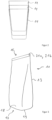
- Fig. 3 shows an isometric view of the Fig. 1 known fluid-tight sealed extrusion blow molded container 11.
- the extrusion blow molded fluid tight sealed container 11 is shown translucent without filling material. It is understood that the extrusion blow-molded container 11 is then sealed in a fluid-tight manner after it has been filled with the filling material.
- the extrusion blow-molded container 11 has a substantially rectangular container base 18 at the second end 17 of the container body 13.
- the opposing sealing surfaces 21a, 21b have been pressed against one another and, in the present exemplary embodiment, have been inextricably connected to one another under the influence of heat.
- the first and second sections 35, 37 preferably include a second angle ⁇ which is greater than or equal to 0° and less than or equal to.
- the second angle ⁇ included between the first section 35 and the second section 37 is 90°. Because the closure element 23 is arranged approximately centrally in the first section 35, the closure element 23 is also spaced from the central axis II of the container 11 and is therefore eccentric. Furthermore, the neck 31 with its outlet opening 29 can be made from a position extending essentially parallel to the central axis II of the container 11, as in Fig. 4 shown, moved.
- the two sealing surfaces 21a, 21b are connected to one another in a fluid-tight, non-detachable manner by welding or gluing.
- the fluid-tight sealed extrusion blow-molded container 11 can be emptied by, for example, using scissors or a knife to remove a container corner on the first edge 15 and emptying the contents via this removed container corner becomes.
Landscapes
- Engineering & Computer Science (AREA)
- Mechanical Engineering (AREA)
- Containers Having Bodies Formed In One Piece (AREA)
- Blow-Moulding Or Thermoforming Of Plastics Or The Like (AREA)
- Packages (AREA)
- Separation Using Semi-Permeable Membranes (AREA)
- Infusion, Injection, And Reservoir Apparatuses (AREA)
- Shaping Of Tube Ends By Bending Or Straightening (AREA)
Applications Claiming Priority (2)
| Application Number | Priority Date | Filing Date | Title |
|---|---|---|---|
| CH01569/15A CH711690A1 (de) | 2015-10-27 | 2015-10-27 | Kunststofftube. |
| PCT/EP2016/075824 WO2017072185A1 (de) | 2015-10-27 | 2016-10-26 | Extrusionsblasgeformter behälter |
Publications (3)
| Publication Number | Publication Date |
|---|---|
| EP3368438A1 EP3368438A1 (de) | 2018-09-05 |
| EP3368438C0 EP3368438C0 (de) | 2023-12-20 |
| EP3368438B1 true EP3368438B1 (de) | 2023-12-20 |
Family
ID=54364944
Family Applications (2)
| Application Number | Title | Priority Date | Filing Date |
|---|---|---|---|
| EP16790920.9A Active EP3368438B1 (de) | 2015-10-27 | 2016-10-26 | Extrusionsblasgeformter behälter |
| EP16787845.3A Active EP3368437B1 (de) | 2015-10-27 | 2016-10-26 | Kunststofftube |
Family Applications After (1)
| Application Number | Title | Priority Date | Filing Date |
|---|---|---|---|
| EP16787845.3A Active EP3368437B1 (de) | 2015-10-27 | 2016-10-26 | Kunststofftube |
Country Status (9)
| Country | Link |
|---|---|
| US (1) | US10494149B2 (pl) |
| EP (2) | EP3368438B1 (pl) |
| CN (2) | CN108290670B (pl) |
| BR (1) | BR112018008327A2 (pl) |
| CH (1) | CH711690A1 (pl) |
| ES (1) | ES2970544T3 (pl) |
| MX (2) | MX2018005196A (pl) |
| PL (1) | PL3368438T3 (pl) |
| WO (2) | WO2017072188A1 (pl) |
Families Citing this family (4)
| Publication number | Priority date | Publication date | Assignee | Title |
|---|---|---|---|---|
| CH716758A1 (de) | 2019-10-31 | 2021-05-14 | Alpla Werke Alwin Lehner Gmbh & Co Kg | Extrusionsblasgeformter Behälter. |
| JP2023548592A (ja) * | 2020-11-05 | 2023-11-17 | ノードソン コーポレーション | ベント付きの可撓性バッグ式ディスペンシング容器 |
| CH718284A1 (de) | 2021-01-26 | 2022-07-29 | Alpla Werke Alwin Lehner Gmbh & Co Kg | Behälter aus einem Kunststoffmaterial mit einer Einfüllöffnung und einer separaten Ausgiessöffnung. |
| CH719938A1 (de) | 2022-07-28 | 2024-02-15 | Alpla Werke Alwin Lehner Gmbh & Co Kg | Behälter aus einem Kunststoffmaterial mit Schraubkappe. |
Citations (3)
| Publication number | Priority date | Publication date | Assignee | Title |
|---|---|---|---|---|
| US5013517A (en) * | 1987-01-30 | 1991-05-07 | Robbins Edward S Iii | Method of blow molding integral press-lock container |
| US20100172600A1 (en) * | 2009-01-06 | 2010-07-08 | The Coca-Cola Company | Flexible container and method of making the same |
| EP2910486A1 (en) * | 2012-10-03 | 2015-08-26 | Nihon Yamamura Glass Co., Ltd. | Pouch container |
Family Cites Families (13)
| Publication number | Priority date | Publication date | Assignee | Title |
|---|---|---|---|---|
| US2686615A (en) * | 1949-04-15 | 1954-08-17 | Eugene E Stocker | Dispensing tube with heat transfer means for heating the contents thereof |
| US6193088B1 (en) | 1996-02-26 | 2001-02-27 | Monty E. Vincent | Flask vent and method of making same |
| US6135322A (en) * | 1998-05-29 | 2000-10-24 | Cetrangolo; Edward M. | Display apparatus for a collapsible tube dispenser |
| DE19859441A1 (de) * | 1998-12-22 | 2000-06-29 | Dieter Mayer | Sicherheitshaube für Lebensmittelverpackungen |
| FR2794428B1 (fr) * | 1999-06-02 | 2001-08-10 | M R Ind | Procede d'obtention d'un emballage thermo-plastique en forme de boite |
| US7150376B2 (en) * | 2003-11-06 | 2006-12-19 | Chang-Keng Tsai | Double-layered fluid container |
| US9004317B2 (en) * | 2004-07-20 | 2015-04-14 | Sivel | Product packaging and dispensing device comprising a sterile filter bottle which is equipped with a nozzle |
| DE102007002865A1 (de) * | 2007-01-15 | 2008-07-17 | Eric Schliemann | Behälter zur Aufnahme eines Produktes |
| KR200438541Y1 (ko) * | 2007-02-21 | 2008-02-21 | 방원서 | 공기유입구가 형성된 소형 식품 저장용기 |
| US20100175850A1 (en) | 2009-01-09 | 2010-07-15 | Kaucic Edward M | Relief Vent for a Hot Fill Fluid Container |
| US20110103714A1 (en) * | 2009-09-18 | 2011-05-05 | Mark Steele | Package with pressure activated expansion chamber |
| DE102010027847B4 (de) * | 2010-03-31 | 2013-11-28 | Henkel Ag & Co. Kgaa | Verfahren zur Herstellung eines stand- und formstabilen Kunststoffbehälters |
| FR2964089B1 (fr) * | 2010-08-26 | 2014-01-10 | Airlessystems | Distributeur de produit fluide. |
-
2015
- 2015-10-27 CH CH01569/15A patent/CH711690A1/de not_active Application Discontinuation
-
2016
- 2016-10-26 PL PL16790920.9T patent/PL3368438T3/pl unknown
- 2016-10-26 WO PCT/EP2016/075829 patent/WO2017072188A1/de not_active Ceased
- 2016-10-26 EP EP16790920.9A patent/EP3368438B1/de active Active
- 2016-10-26 ES ES16790920T patent/ES2970544T3/es active Active
- 2016-10-26 US US15/771,383 patent/US10494149B2/en active Active
- 2016-10-26 WO PCT/EP2016/075824 patent/WO2017072185A1/de not_active Ceased
- 2016-10-26 MX MX2018005196A patent/MX2018005196A/es unknown
- 2016-10-26 EP EP16787845.3A patent/EP3368437B1/de active Active
- 2016-10-26 MX MX2018005197A patent/MX2018005197A/es unknown
- 2016-10-26 CN CN201680063264.9A patent/CN108290670B/zh active Active
- 2016-10-26 BR BR112018008327-5A patent/BR112018008327A2/pt not_active Application Discontinuation
- 2016-10-26 CN CN201680063420.1A patent/CN108473244B/zh not_active Expired - Fee Related
Patent Citations (3)
| Publication number | Priority date | Publication date | Assignee | Title |
|---|---|---|---|---|
| US5013517A (en) * | 1987-01-30 | 1991-05-07 | Robbins Edward S Iii | Method of blow molding integral press-lock container |
| US20100172600A1 (en) * | 2009-01-06 | 2010-07-08 | The Coca-Cola Company | Flexible container and method of making the same |
| EP2910486A1 (en) * | 2012-10-03 | 2015-08-26 | Nihon Yamamura Glass Co., Ltd. | Pouch container |
Also Published As
| Publication number | Publication date |
|---|---|
| CN108290670B (zh) | 2019-10-29 |
| US10494149B2 (en) | 2019-12-03 |
| MX2018005196A (es) | 2018-08-16 |
| EP3368437A1 (de) | 2018-09-05 |
| MX2018005197A (es) | 2018-08-16 |
| EP3368437B1 (de) | 2022-10-05 |
| US20180346203A1 (en) | 2018-12-06 |
| ES2970544T3 (es) | 2024-05-29 |
| EP3368438C0 (de) | 2023-12-20 |
| CH711690A1 (de) | 2017-04-28 |
| CN108473244B (zh) | 2019-10-11 |
| CN108290670A (zh) | 2018-07-17 |
| CN108473244A (zh) | 2018-08-31 |
| EP3368438A1 (de) | 2018-09-05 |
| WO2017072188A1 (de) | 2017-05-04 |
| BR112018008327A2 (pt) | 2018-10-30 |
| PL3368438T3 (pl) | 2024-04-08 |
| WO2017072185A1 (de) | 2017-05-04 |
Similar Documents
| Publication | Publication Date | Title |
|---|---|---|
| EP0182094B1 (de) | Verfahren zum Herstellen einer mit einer verschliessbaren Öffnung versehenen Verpackung und nach diesem Verfahren hergestellte Verpackung | |
| EP0612664B1 (de) | Verpackung für Fliessmittel, Verfahren zur Herstellung einer solchen Packung und Vorrichtung zur Durchführung des Verfahrens | |
| DE3217156C2 (pl) | ||
| DE2831990C2 (pl) | ||
| EP0052261B1 (de) | Packung für fliessfähige Füllgüter mit wiederverschliessbarer Öffnungsvorrichtung | |
| DE60217026T2 (de) | Ausgiesstülle, sowie Verfahren und Vorrichtung zu deren Fixierung auf einem Beutel | |
| DE60124291T2 (de) | Extrusions-blasgeformter zusammendrückbarer behälter und verfahren zu dessen herstellung | |
| EP0912420B1 (de) | Behälter mit druckausgleichsöffnungen | |
| EP1384681A2 (de) | Beuteltube und Verfahren zur Herstellung derselben | |
| DE2652056A1 (de) | Flexibler, zusammenfaltbarer behaelter sowie verfahren und blasform zu seiner herstellung | |
| WO2017072185A1 (de) | Extrusionsblasgeformter behälter | |
| EP2976206B1 (de) | Extrusionsblasgeformte tube und verfahren | |
| US20070267436A1 (en) | Container and a cap having simultaneous sealing of two orifices | |
| DE2720907C2 (de) | Tubenartiger Behälter und Verfahren zu seiner Herstellung | |
| EP3087008B1 (de) | Verpackung sowie vorrichtung und verfahren zu deren herstellung | |
| EP3019325B1 (de) | Gefässeinrichtung, werkzeugeinrichtung zur herstellung einer zumindest teilweise und/oder zumindest bereichsweise blasgeformten gefässeinrichtung, herstellungsverfahren | |
| DE102007049331A1 (de) | Restentleerbare Behältnisse und deren Herstellung | |
| WO2016066398A1 (de) | Kunststoffbehälter mit siegelbarer behältermündung | |
| EP4633908A1 (de) | VERFAHREN ZUR HERSTELLUNG EINES AUSGIEßELEMENTES UND AUSGIEßELEMENT | |
| WO2011124508A1 (de) | VERFAHREN ZUM HERSTELLEN UND/ODER BEFÜLLEN EINER PACKUNG FÜR FLIEßFÄHIGE PRODUKTE | |
| WO2017064062A1 (de) | Spritzgegossener preform zur herstellung eines kunststoffbehälters in einem blasverfahren, daraus hergestellter kunststoffbehälter und herstellverfahren für den preform bzw. den kunststoffbehälter | |
| DE60309495T2 (de) | Verpackung für frei fliessende oder pastöse produkte | |
| EP4495019A1 (de) | Extrusionsblasgeformter behälter | |
| DE102022133763B4 (de) | Verfahren zur Herstellung eines Ausgießelementes und Ausgießelement | |
| CH716758A1 (de) | Extrusionsblasgeformter Behälter. |
Legal Events
| Date | Code | Title | Description |
|---|---|---|---|
| STAA | Information on the status of an ep patent application or granted ep patent |
Free format text: STATUS: UNKNOWN |
|
| STAA | Information on the status of an ep patent application or granted ep patent |
Free format text: STATUS: THE INTERNATIONAL PUBLICATION HAS BEEN MADE |
|
| PUAI | Public reference made under article 153(3) epc to a published international application that has entered the european phase |
Free format text: ORIGINAL CODE: 0009012 |
|
| STAA | Information on the status of an ep patent application or granted ep patent |
Free format text: STATUS: REQUEST FOR EXAMINATION WAS MADE |
|
| 17P | Request for examination filed |
Effective date: 20180524 |
|
| AK | Designated contracting states |
Kind code of ref document: A1 Designated state(s): AL AT BE BG CH CY CZ DE DK EE ES FI FR GB GR HR HU IE IS IT LI LT LU LV MC MK MT NL NO PL PT RO RS SE SI SK SM TR |
|
| AX | Request for extension of the european patent |
Extension state: BA ME |
|
| DAV | Request for validation of the european patent (deleted) | ||
| DAX | Request for extension of the european patent (deleted) | ||
| STAA | Information on the status of an ep patent application or granted ep patent |
Free format text: STATUS: EXAMINATION IS IN PROGRESS |
|
| 17Q | First examination report despatched |
Effective date: 20220421 |
|
| GRAP | Despatch of communication of intention to grant a patent |
Free format text: ORIGINAL CODE: EPIDOSNIGR1 |
|
| STAA | Information on the status of an ep patent application or granted ep patent |
Free format text: STATUS: GRANT OF PATENT IS INTENDED |
|
| INTG | Intention to grant announced |
Effective date: 20230405 |
|
| GRAJ | Information related to disapproval of communication of intention to grant by the applicant or resumption of examination proceedings by the epo deleted |
Free format text: ORIGINAL CODE: EPIDOSDIGR1 |
|
| STAA | Information on the status of an ep patent application or granted ep patent |
Free format text: STATUS: EXAMINATION IS IN PROGRESS |
|
| INTC | Intention to grant announced (deleted) | ||
| GRAP | Despatch of communication of intention to grant a patent |
Free format text: ORIGINAL CODE: EPIDOSNIGR1 |
|
| STAA | Information on the status of an ep patent application or granted ep patent |
Free format text: STATUS: GRANT OF PATENT IS INTENDED |
|
| INTG | Intention to grant announced |
Effective date: 20230707 |
|
| GRAS | Grant fee paid |
Free format text: ORIGINAL CODE: EPIDOSNIGR3 |
|
| GRAA | (expected) grant |
Free format text: ORIGINAL CODE: 0009210 |
|
| STAA | Information on the status of an ep patent application or granted ep patent |
Free format text: STATUS: THE PATENT HAS BEEN GRANTED |
|
| RAP3 | Party data changed (applicant data changed or rights of an application transferred) |
Owner name: ALPLA-WERKE ALWIN LEHNER GMBH & CO.KG |
|
| AK | Designated contracting states |
Kind code of ref document: B1 Designated state(s): AL AT BE BG CH CY CZ DE DK EE ES FI FR GB GR HR HU IE IS IT LI LT LU LV MC MK MT NL NO PL PT RO RS SE SI SK SM TR |
|
| REG | Reference to a national code |
Ref country code: GB Ref legal event code: FG4D Free format text: NOT ENGLISH |
|
| REG | Reference to a national code |
Ref country code: CH Ref legal event code: EP |
|
| REG | Reference to a national code |
Ref country code: DE Ref legal event code: R096 Ref document number: 502016016288 Country of ref document: DE |
|
| REG | Reference to a national code |
Ref country code: IE Ref legal event code: FG4D Free format text: LANGUAGE OF EP DOCUMENT: GERMAN |
|
| U01 | Request for unitary effect filed |
Effective date: 20240118 |
|
| U07 | Unitary effect registered |
Designated state(s): AT BE BG DE DK EE FI FR IT LT LU LV MT NL PT SE SI Effective date: 20240126 |
|
| REG | Reference to a national code |
Ref country code: CH Ref legal event code: PK Free format text: BERICHTIGUNGEN |
|
| PG25 | Lapsed in a contracting state [announced via postgrant information from national office to epo] |
Ref country code: GR Free format text: LAPSE BECAUSE OF FAILURE TO SUBMIT A TRANSLATION OF THE DESCRIPTION OR TO PAY THE FEE WITHIN THE PRESCRIBED TIME-LIMIT Effective date: 20240321 |
|
| PG25 | Lapsed in a contracting state [announced via postgrant information from national office to epo] |
Ref country code: GR Free format text: LAPSE BECAUSE OF FAILURE TO SUBMIT A TRANSLATION OF THE DESCRIPTION OR TO PAY THE FEE WITHIN THE PRESCRIBED TIME-LIMIT Effective date: 20240321 |
|
| REG | Reference to a national code |
Ref country code: ES Ref legal event code: FG2A Ref document number: 2970544 Country of ref document: ES Kind code of ref document: T3 Effective date: 20240529 |
|
| PG25 | Lapsed in a contracting state [announced via postgrant information from national office to epo] |
Ref country code: RS Free format text: LAPSE BECAUSE OF FAILURE TO SUBMIT A TRANSLATION OF THE DESCRIPTION OR TO PAY THE FEE WITHIN THE PRESCRIBED TIME-LIMIT Effective date: 20231220 Ref country code: NO Free format text: LAPSE BECAUSE OF FAILURE TO SUBMIT A TRANSLATION OF THE DESCRIPTION OR TO PAY THE FEE WITHIN THE PRESCRIBED TIME-LIMIT Effective date: 20240320 Ref country code: HR Free format text: LAPSE BECAUSE OF FAILURE TO SUBMIT A TRANSLATION OF THE DESCRIPTION OR TO PAY THE FEE WITHIN THE PRESCRIBED TIME-LIMIT Effective date: 20231220 |
|
| PG25 | Lapsed in a contracting state [announced via postgrant information from national office to epo] |
Ref country code: IS Free format text: LAPSE BECAUSE OF FAILURE TO SUBMIT A TRANSLATION OF THE DESCRIPTION OR TO PAY THE FEE WITHIN THE PRESCRIBED TIME-LIMIT Effective date: 20240420 |
|
| PG25 | Lapsed in a contracting state [announced via postgrant information from national office to epo] |
Ref country code: CZ Free format text: LAPSE BECAUSE OF FAILURE TO SUBMIT A TRANSLATION OF THE DESCRIPTION OR TO PAY THE FEE WITHIN THE PRESCRIBED TIME-LIMIT Effective date: 20231220 |
|
| PG25 | Lapsed in a contracting state [announced via postgrant information from national office to epo] |
Ref country code: SK Free format text: LAPSE BECAUSE OF FAILURE TO SUBMIT A TRANSLATION OF THE DESCRIPTION OR TO PAY THE FEE WITHIN THE PRESCRIBED TIME-LIMIT Effective date: 20231220 |
|
| PG25 | Lapsed in a contracting state [announced via postgrant information from national office to epo] |
Ref country code: SM Free format text: LAPSE BECAUSE OF FAILURE TO SUBMIT A TRANSLATION OF THE DESCRIPTION OR TO PAY THE FEE WITHIN THE PRESCRIBED TIME-LIMIT Effective date: 20231220 Ref country code: SK Free format text: LAPSE BECAUSE OF FAILURE TO SUBMIT A TRANSLATION OF THE DESCRIPTION OR TO PAY THE FEE WITHIN THE PRESCRIBED TIME-LIMIT Effective date: 20231220 Ref country code: RO Free format text: LAPSE BECAUSE OF FAILURE TO SUBMIT A TRANSLATION OF THE DESCRIPTION OR TO PAY THE FEE WITHIN THE PRESCRIBED TIME-LIMIT Effective date: 20231220 Ref country code: IS Free format text: LAPSE BECAUSE OF FAILURE TO SUBMIT A TRANSLATION OF THE DESCRIPTION OR TO PAY THE FEE WITHIN THE PRESCRIBED TIME-LIMIT Effective date: 20240420 Ref country code: CZ Free format text: LAPSE BECAUSE OF FAILURE TO SUBMIT A TRANSLATION OF THE DESCRIPTION OR TO PAY THE FEE WITHIN THE PRESCRIBED TIME-LIMIT Effective date: 20231220 |
|
| REG | Reference to a national code |
Ref country code: DE Ref legal event code: R097 Ref document number: 502016016288 Country of ref document: DE |
|
| PLBE | No opposition filed within time limit |
Free format text: ORIGINAL CODE: 0009261 |
|
| STAA | Information on the status of an ep patent application or granted ep patent |
Free format text: STATUS: NO OPPOSITION FILED WITHIN TIME LIMIT |
|
| 26N | No opposition filed |
Effective date: 20240923 |
|
| U20 | Renewal fee for the european patent with unitary effect paid |
Year of fee payment: 9 Effective date: 20241028 |
|
| PG25 | Lapsed in a contracting state [announced via postgrant information from national office to epo] |
Ref country code: MC Free format text: LAPSE BECAUSE OF FAILURE TO SUBMIT A TRANSLATION OF THE DESCRIPTION OR TO PAY THE FEE WITHIN THE PRESCRIBED TIME-LIMIT Effective date: 20231220 |
|
| PG25 | Lapsed in a contracting state [announced via postgrant information from national office to epo] |
Ref country code: IE Free format text: LAPSE BECAUSE OF NON-PAYMENT OF DUE FEES Effective date: 20241026 |
|
| REG | Reference to a national code |
Ref country code: CH Ref legal event code: U11 Free format text: ST27 STATUS EVENT CODE: U-0-0-U10-U11 (AS PROVIDED BY THE NATIONAL OFFICE) Effective date: 20251101 |
|
| U20 | Renewal fee for the european patent with unitary effect paid |
Year of fee payment: 10 Effective date: 20251027 |
|
| PGFP | Annual fee paid to national office [announced via postgrant information from national office to epo] |
Ref country code: GB Payment date: 20251024 Year of fee payment: 10 |
|
| PGFP | Annual fee paid to national office [announced via postgrant information from national office to epo] |
Ref country code: CH Payment date: 20251101 Year of fee payment: 10 |
|
| PGFP | Annual fee paid to national office [announced via postgrant information from national office to epo] |
Ref country code: PL Payment date: 20251014 Year of fee payment: 10 |
|
| PG25 | Lapsed in a contracting state [announced via postgrant information from national office to epo] |
Ref country code: CY Free format text: LAPSE BECAUSE OF FAILURE TO SUBMIT A TRANSLATION OF THE DESCRIPTION OR TO PAY THE FEE WITHIN THE PRESCRIBED TIME-LIMIT; INVALID AB INITIO Effective date: 20161026 |
|
| PGFP | Annual fee paid to national office [announced via postgrant information from national office to epo] |
Ref country code: ES Payment date: 20251114 Year of fee payment: 10 |
|
| PG25 | Lapsed in a contracting state [announced via postgrant information from national office to epo] |
Ref country code: HU Free format text: LAPSE BECAUSE OF FAILURE TO SUBMIT A TRANSLATION OF THE DESCRIPTION OR TO PAY THE FEE WITHIN THE PRESCRIBED TIME-LIMIT; INVALID AB INITIO Effective date: 20161026 |