EP3359309B1 - Luftgekühltes hochdruckreinigungsgerät - Google Patents
Luftgekühltes hochdruckreinigungsgerät Download PDFInfo
- Publication number
- EP3359309B1 EP3359309B1 EP16757025.8A EP16757025A EP3359309B1 EP 3359309 B1 EP3359309 B1 EP 3359309B1 EP 16757025 A EP16757025 A EP 16757025A EP 3359309 B1 EP3359309 B1 EP 3359309B1
- Authority
- EP
- European Patent Office
- Prior art keywords
- cooling air
- housing
- cleaning device
- channel
- pressure cleaning
- Prior art date
- Legal status (The legal status is an assumption and is not a legal conclusion. Google has not performed a legal analysis and makes no representation as to the accuracy of the status listed.)
- Active
Links
Images


Classifications
-
- B—PERFORMING OPERATIONS; TRANSPORTING
- B08—CLEANING
- B08B—CLEANING IN GENERAL; PREVENTION OF FOULING IN GENERAL
- B08B3/00—Cleaning by methods involving the use or presence of liquid or steam
- B08B3/02—Cleaning by the force of jets or sprays
- B08B3/026—Cleaning by making use of hand-held spray guns; Fluid preparations therefor
-
- B—PERFORMING OPERATIONS; TRANSPORTING
- B08—CLEANING
- B08B—CLEANING IN GENERAL; PREVENTION OF FOULING IN GENERAL
- B08B2203/00—Details of cleaning machines or methods involving the use or presence of liquid or steam
- B08B2203/02—Details of machines or methods for cleaning by the force of jets or sprays
- B08B2203/0223—Electric motor pumps
-
- B—PERFORMING OPERATIONS; TRANSPORTING
- B08—CLEANING
- B08B—CLEANING IN GENERAL; PREVENTION OF FOULING IN GENERAL
- B08B2203/00—Details of cleaning machines or methods involving the use or presence of liquid or steam
- B08B2203/02—Details of machines or methods for cleaning by the force of jets or sprays
- B08B2203/0235—Cooling the motor pump
Definitions
- the invention relates to an air-cooled high-pressure cleaning device, comprising a housing and a motor pump unit accommodated therein with a motor and a high-pressure pump driven by the motor, as well as at least one cooling air channel arranged or formed in the housing for cooling air for cooling the motor pump unit, which is fluidly connected to the atmosphere via at least one housing opening.
- Water cooling and air cooling are used to cool high-pressure cleaning devices.
- Water cooling can be used to effectively cool the motor pump unit, but it requires more equipment than air cooling.
- the motor pump unit In order to provide effective air cooling, the motor pump unit should be supplied with as high a volume flow of cooling air as possible.
- airborne noise due to the flowing cooling air and structure-borne noise due to the motor pump unit in operation lead to a not insignificant emission of operating noise. It is desirable to keep noise emissions as low as possible in order to make working with the high-pressure cleaning device as pleasant as possible for the user and to meet any noise protection requirements.
- the DE 41 06 955 A1 and the same content EP 0 503 298 A1 describe an air-cooled high-pressure cleaning device.
- the DE 103 05 812 A1 describes a high-pressure cleaning device with a housing and a motor pump unit, which is arranged in the housing and is completely surrounded by a sound-absorbing material.
- the inflowing liquid is used to cool the motor of the motor pump unit.
- air cooling is used.
- Another air-cooled high-pressure cleaning device is in the DE 295 22 275 U1 described.
- the object of the present invention is to provide a high-pressure cleaning device of the type mentioned above which has a lower noise emission.
- an air guide part which at least partially surrounds the motor pump unit. Cooling air can flow through the at least one cooling air channel and the air guide part and thereby ensure effective cooling of the motor pump unit.
- At least one cooling air channel is provided, in particular a cooling air channel through which cooling air from the atmosphere is supplied to the air guide part. Alternatively or additionally, it can be provided that cooling air is released from the air guide part into the atmosphere via a cooling air channel.
- the at least one cooling air channel enables the cooling air flow to be made more uniform, so that the noise emission as a result of the air flow in the high-pressure cleaning device according to the invention can be kept as low as possible.
- the damping elements are provided, via which the air guide part is supported on the housing.
- the damping elements make it possible to ensure vibration decoupling of the air guide part relative to the housing.
- the air guide part can be attached via the damping elements, for example, to elements arranged in the housing or connected to it. formed housing walls or other types of support elements (projections, bases, partition walls, etc.).
- the vibration decoupling can further reduce the noise emissions of the high-pressure cleaning device due to structure-borne noise and, as a result, provide a particularly quiet high-pressure cleaning device.
- the at least one cooling air channel is formed at least in sections between an outer wall of the housing and at least one further channel wall enclosed or formed by the housing at a distance from the outer wall.
- the at least one cooling air channel can thus be formed integrally by the housing.
- the outer wall can form a wall of the cooling air channel at least in sections in order to simplify the design of the at least one cooling air channel.
- the air guide part is free from direct contact with the housing and/or walls of the at least one cooling air duct. In this way, vibrations of the air guide part are not transmitted directly to the housing, especially to walls of the at least one cooling air duct. Instead, the damping elements are effective to dampen vibrations of the air guide part.
- the motor pump unit is free from direct contact with the housing and/or walls of the at least one cooling air duct.
- the air guide part preferably extends over the entire or substantially entire length of the motor pump unit. This makes it possible to ensure a defined cooling air flow over the entire or substantially entire length of the motor pump unit.
- Individual sections of the motor pump unit such as a pump head, a pump inlet or a pump outlet on a front side of the motor pump unit, can be arranged entirely or partially outside the air guide part.
- the air guide part surrounds the motor pump unit in the form of a jacket and has an opening on at least one end side, in particular a front side, through which the at least one air guide channel and the air guide part open into one another.
- the air guide part can surround the motor pump unit on all sides in the circumferential direction and for this purpose can have, for example, a cylindrical or essentially cylindrical shape.
- At least one end side, in particular at least one of the front sides of the air guide part there is preferably an opening through which a flow connection between the interior of the air guide part and the at least one cooling air channel is ensured.
- a sealing element is preferably arranged on the edge of the at least one opening in order to provide a tight flow connection between the at least one cooling air duct and the air guide part.
- the sealing element for example a ring seal, ensures the tightest possible flow connection. Any noise from the flowing cooling air that could otherwise escape between the at least one cooling air duct and the air guide part can be avoided in this way.
- the sealing element can also have a damping effect and in particular provide a damping element. This can bring about an additional vibration-decoupling effect between the air guide part and the at least one cooling air duct on the edge of the at least one opening.
- the motor pump unit advantageously has a fan wheel driven by a shaft of the motor, which is arranged at an opening in the air guide part and conveys cooling air over the motor pump unit.
- the fan wheel is positioned, for example, at a front opening and conveys the cooling air over the motor and the pump through the air guide part. In this way, effective cooling of the motor pump unit can be ensured.
- a pump inlet line and/or a pump outlet line are led out of the air guide part through an end opening of the air guide part or that a pump head of the high-pressure pump passes through the opening.
- the pump inlet line for supplying cleaning fluid to be pressurized and/or the pump outlet line for pressurized cleaning fluid can, for example, be led through the opening of the air guide part and through the cooling air channel and exit from the housing.
- the pump inlet line and/or the pump outlet line are led out of the air guide part laterally, for example transversely to the axial direction.
- the housing has or forms housing walls between which and the air guide part the damping elements are positioned for support on the housing walls.
- the housing walls are arranged or formed inside the housing.
- the air guide part rests on the housing walls via the damping elements. In an advantageous embodiment, this makes it possible, for example, to ensure that the air guide part is supported over a large area inside the housing, whereby vibrations of the air guide part can be diverted and dampened over a large area.
- the housing walls are advantageously aligned transversely to an axial direction of the motor pump unit.
- the housing walls are intermediate walls or partitions that are arranged transversely to the axial direction in the housing.
- the housing walls are double-walled and the damping elements engage between wall sections of the double-walled housing walls.
- This makes it possible to fix the damping elements to the housing walls and to secure the position of the air guide part within the housing.
- the damping elements can in the axial direction on the wall sections of the housing walls to prevent axial movement of the air guide part. Radial movement of the air guide part can be prevented, for example, by webs connecting the wall sections, on which the damping elements can also be supported.
- the damping elements are designed in the shape of a ring or ring segment and at least partially surround the air guide part.
- the damping elements are advantageously arranged in a plane transverse to an axial direction of the motor pump unit. It can advantageously be provided that the damping elements are ring segment sections, at least two of which are arranged at an axial position of the motor pump unit.
- the housing is constructed from housing half-shells, as will be discussed below. A respective segment can be positioned on a housing half-shell.
- the motor pump unit with the air guide part surrounding it can then be inserted into the housing half-shell.
- the further housing half-shell with the further segment arranged on it can then be positioned over the first housing half-shell and joined to it.
- the assembly of the high-pressure cleaning device can therefore be carried out particularly easily.
- At least one damping element is arranged at at least two positions spaced apart from one another for supporting the air guide part on the housing.
- a pair of ring-segment-shaped damping elements is present at each position.
- the damping elements are made of a rubber material or a plastic material, for example.
- damping elements are removable after opening the housing and in particular can be removed manually. This makes it easy to replace damping elements as the high-pressure cleaning device ages, which means that the low-noise operation of the high-pressure cleaning device can be maintained.
- the at least one further channel wall is preferably free of contact with the damping elements. Any vibrations not absorbed by the damping elements are therefore not directly transmitted to the channel wall. In practice, this proves to be advantageous for further reducing noise emissions.
- the at least one cooling air channel runs with a channel section in a longitudinal direction of the high-pressure cleaning device and preferably extends in the transverse direction of the high-pressure cleaning device over its entire or essentially entire width.
- the at least one cooling air channel can in particular extend over the entire or essentially entire length of the high-pressure cleaning device.
- the high-pressure cleaning device can thus have a compact structure.
- the motor pump unit with the air guide part is accommodated in the interior formed by the housing and supported on the housing via the damping elements.
- the at least one cooling air channel can run over the entire length and/or width of the high-pressure cleaning device.
- the at least one cooling air duct is lined on the inside at least in sections with a sound-absorbing material.
- the sound-absorbing material for example a foam material, can further reduce noise emissions.
- noise from the motor pump unit can be absorbed.
- flow noise of the cooling air in the cooling air duct is dampened by the sound-absorbing material.
- the at least one cooling air channel is designed to be angled, and the cooling air flowing through the at least one cooling air channel is deflected at least once. It has been shown in practice that the noise emission due to the air flow can be reduced by deflecting it at least once. In the area of the bend, which leads to a deflection of the cooling air of advantageously approximately 90°, the at least one cooling air duct is advantageously lined with a sound-absorbing material.
- the motor pump unit is advantageously aligned parallel to a channel section of the at least one cooling air channel, and the cooling air flowing through the channel section and the air guide part is advantageously deflected twice, preferably by approximately 90° each time.
- the cooling air flowing through the channel section and through the air guide part can therefore flow in opposite directions. With a compact design of the high-pressure cleaning device, this enables a relatively long air flow within the housing and a high level of noise reduction is achieved.
- the cooling air advantageously flows approximately along a U through the at least one cooling air channel, which can be L-shaped in cross-section, for example, and the air guide part.
- the high-pressure cleaning device has a first cooling air channel through which cooling air from the atmosphere can be supplied to the motor pump unit, and a second cooling air channel through which cooling air can be discharged from the motor pump unit into the atmosphere.
- the air guide part then advantageously has a respective opening on opposite end sides and in particular front sides, through which the first cooling air channel opens into the air guide part and through which the air guide part opens into the second cooling air channel.
- the motor pump unit and the air guide part are arranged between channel sections of the first and second cooling air channel that run parallel to the motor pump unit and if the cooling air flows along a meander and in particular a rectangular meander through the first cooling air channel, the air guide part and the second cooling air channel.
- the cooling air is deflected several times along the rectangular meander, in particular along an "S" or "square S".
- the channel section of the first cooling air channel is arranged above and the channel section of the second cooling air channel is arranged below the motor pump unit.
- the channel sections of the cooling channels can be arranged laterally next to the motor pump unit.
- Position and orientation information such as "above”, “below”, “horizontal” or the like are to be understood in this case as relating to a positioning of the high-pressure cleaning device in a position of use on a floor surface considered to be horizontal.
- a contact plane defined by the high-pressure cleaning device coincides with a contact plane defined by the floor surface.
- a housing opening through which cooling air enters the first cooling air channel and a housing opening through which cooling air exits the second cooling air channel are arranged on opposite sides of the housing. This can prevent heated cooling air exiting the second cooling air channel from entering the first cooling air channel directly. This can largely prevent any impairment of the cooling effect. If possible, the housing openings can be arranged on the high-pressure cleaning device with a maximum distance from one another.
- a housing opening through which cooling air enters the first cooling air duct is positioned above a housing opening through which cooling air exits the second cooling air duct, relative to a height direction of the high-pressure cleaning device.
- the housing opening through which cooling air enters the first cooling air channel is located on the top of the high-pressure cleaning device. In this way, foreign substances or dirt particles are only sucked into the first cooling air channel with a relatively low probability, which is particularly advantageous when the high-pressure cleaning device is positioned on a floor surface.
- the motor pump unit is aligned horizontally in the housing, in which case the bottom surface is also assumed to be aligned horizontally.
- the above-mentioned channel sections of the first and/or the second cooling air channel, advantageously above and below the motor pump unit, are then preferably also aligned horizontally.
- the first and/or second cooling air duct can have further duct sections which can be aligned vertically, in particular when the respective cooling air duct has an L-shaped cross-section.
- the housing has two housing half shells, whereby the motor pump unit with the air guide part surrounding it is positioned between the housing half shells and is supported by the damping elements on the front sides of the housing walls of each housing half shell, with several front sides facing the other housing half shell. This makes it easy to assemble the high-pressure cleaning device.
- the high-pressure pump for example, is an axial piston pump.
- the drawing shows an advantageous embodiment of an air-cooled high-pressure cleaning device according to the invention, designated with the reference number 10.
- the high-pressure cleaning device 10 comprises a housing 12, which in an advantageous embodiment is constructed from two housing half-shells 14, 16.
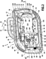
- the Figure 1 The housing half shell 14 shown facing the user is in the Figures 2 and 3 hidden to allow a view into the interior of the housing 12.
- the housing 12 has a bottom side 18, a top side 20, a front side 22 and a back side 24. Via the bottom side 12, which defines a contact plane, the high-pressure cleaning device 10 can be positioned in a use position on a floor surface (not shown) assumed to be horizontal.
- the housing 12 is designed like a case and comprises a carrying handle 26 on the upper side 12 for carrying the high-pressure cleaning device 10.
- each housing half-shell 14, 16 forms a section of the corresponding wall in the advantageous embodiment of the high-pressure cleaning device 10.
- the structure of the housing 12 with the corresponding walls is explained below using the example of the housing half-shell 16 ( Figures 2 and 3 ), whereby the corresponding statements also apply to the other housing half-shell 14, which forms these walls together with the housing half-shell 16.
- the housing 12 has an outer wall 28.
- the outer wall 28 is designed as a double wall on the top side 20 and on the bottom side 18 to reinforce the housing 12.
- a plurality of openings are formed in the outer wall 28 at the transition from the underside 18 to the rear side 24. These openings are collectively referred to as the housing opening 32.
- the outer wall 28 is single-walled. Starting from the outer wall 28, a channel wall 34 branches off into the housing interior, which is connected at the top side 20 to the double-walled section of the outer wall 28.
- the outer wall 28 on the front side 22 is single-walled approximately in the middle between the bottom side 18 and the top side 20. Above this, the outer wall 28 is double-walled over a small section. In the direction On the underside 18, a channel wall 36 branches off from the outer wall 28 into the interior of the housing 12, which is connected to the outer wall 28 on the underside 18, close to the double-walled section of the outer wall 28 there.
- a further channel wall 38 is formed inside the housing 12.
- the channel wall 38 has four sections.
- a first section 40 begins at the front 22 below the housing opening 30.
- the first section 40 is slightly rising and merges into a second section 42.
- the second section 42 runs horizontally and parallel to the outer wall 38 at its double-walled section, approximately over the length of the carrying handle 26.
- the second section 42 merges into an approximately vertical third section 44 which extends in the direction of the underside 18, beyond the middle of the high-pressure cleaning device 10 between the top side 20 and the bottom side 18.
- the third section 44 has a recess 48 which is semicircular.
- a fourth section 46 connects the third section 44 approximately horizontally to the outer wall 28 at the rear side 24.
- a further channel wall 50 is formed inside the housing 12. Starting from the rear side 24 in the direction of the front side 22, the channel wall 50 comprises a first section 52.
- the first section 52 starts from the outer wall 28 on the rear side 24 above the housing opening 32.
- the first section 52 slopes slightly towards the bottom side 18 and merges into a second section 52.
- the second section 54 runs horizontally and parallel to the outer wall 28 at its double-walled section.
- the second section 54 merges into a third section 56 which is C-shaped in cross section, so that the channel wall 50 is first curved towards the top side 20 and then towards the back side 24.
- the third section 56 is followed by a fourth section 58.
- the fourth section runs approximately vertically in the direction of the upper side 22 and is provided, for example, with a step 60.
- the fourth section 58 is connected to the first section 40 or the second section 42 of the channel wall 38.
- a recess 62 is formed in the fourth section 58, which is semicircular.
- the housing 12 is essentially divided into three sections on the inside, namely a first cooling air channel 64, a receiving space 66 and a second cooling air channel 68.
- the first cooling air channel extends from the housing opening 30 with a channel section 70 in the longitudinal direction 72 of the high-pressure cleaning device 10 and essentially over its entire length.
- the channel section 70 is limited at the top by the outer wall 28 and at the bottom by the sections 40 and 42 of the channel wall 38.
- the channel section 70 is followed by an approximately vertically extending channel section 74 which is formed between the third section 44, the channel wall 34, the outer wall 28 and the fourth section 46.
- the channel section 74 extends to the lower edge of the recess 48.
- the first cooling air channel 64 extends in the transverse direction 76 of the high-pressure cleaning device 10 over its entire width.
- Cooling air can be supplied to the motor pump unit of the high-pressure cleaning device 10, which will be explained below, through the first cooling air channel 64.
- the first cooling air channel 64 has an approximately L-shape, ie the cooling air channel 64 is angled. In the transition from the channel section 70 to the channel section 74, the cooling air is diverted by approximately 90°. The cooling air undergoes a further deflection of approximately 90° from the second channel section 74 as it passes through the recess 48 (see below).
- the first cooling air channel 64 is lined in sections with a sound-absorbing material 78.
- the sound-absorbing material 78 for example a foam material, is arranged on the inside of the outer wall 28, for example, at least above the second section 42, and extends to the channel wall 34. Sound-absorbing material 78 can also run on the inside of the channel wall 34 and the outer wall up to the fourth section 46. Sound-absorbing material 78 is advantageously also arranged on the second section 42.
- the second cooling air channel 68 extends from the recess 62 with a channel section 80 approximately vertically in the direction of the underside 18.
- the channel section 80 is delimited by the section 40, the sections 56 and 58 of the channel wall 50, the outer wall 28 and the channel wall 36.
- the channel section 80 merges into a channel section 82 which extends from the channel wall 36 to the rear side 24.
- the channel section 82 thus extends in the longitudinal direction 72 almost over the entire length of the high-pressure cleaning device 10.
- the channel section 82 is delimited at the top by the sections 54 and 52 and at the bottom by the outer wall 28.
- the cooling air duct 68 also extends over the entire width of the high-pressure cleaning device 10.
- the second cooling air channel 68 also has an L-shaped cross-section with an angle between the channel sections 80, 82.
- cooling air is deflected by approximately 90° shortly behind the recess 62. A further deflection by approximately 90° occurs in the area of the bend between channel sections 80 and 82.
- the second cooling air duct 68 is also lined in sections with the sound-absorbing material 78.
- Sound-absorbing material 78 is arranged, for example, on the inside of the outer wall 28, in particular opposite the second section 54, on which sound-absorbing material 78 is preferably also arranged. Sound-absorbing material 78 is also advantageously arranged along the duct wall 38 and the outer wall 28 up to the first section 40.
- the receiving space 66 is formed between the channel walls 38 and 50.
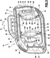
- the housing 12 comprises housing walls 84 and 86 in the receiving space 66.
- Each housing wall 84, 86 is aligned transversely to the longitudinal direction 72 and is designed as a double wall with wall sections 88 and 90.
- Webs 92 connect the wall sections 88 and 90.
- a recess 94 is present on each housing wall 84, 86.
- the housing walls 84, 86 are spaced apart from one another in the longitudinal direction 72.
- the housing wall 84 is arranged approximately in the region of the rear end of the carrying handle 26 and the housing wall 86 is arranged approximately in the region of the front end of the carrying handle 26.
- this arrangement could also be different.
- the housing walls 84, 86 are, in a sense, partition walls which divide the receiving space 66 in the longitudinal direction 72 and are aligned in the transverse direction 76.
- the high-pressure cleaning device 10 has a motor pump unit 96.
- the motor pump unit 96 comprises a motor 98 with a shaft 100 that defines an axis 102.
- the motor pump unit 96 is arranged on the high-pressure cleaning device 10 in such a way that the axis 102 runs in the longitudinal direction 72, i.e. the longitudinal direction 72 is an axial direction.
- the axis 102 is aligned horizontally, i.e. it runs parallel to the contact plane defined by the high-pressure cleaning device 10.
- the motor pump unit 96 further comprises a high-pressure pump 104, which is designed as an axial piston pump.
- the high-pressure pump 104 comprises a pump head 106, on which a pump inlet line 108 and a pump outlet line 110 are arranged.
- a fan wheel 112 is held in a rotationally fixed manner on the shaft 100.
- the motor pump unit 96 is accommodated in the housing 12 in such a way that, starting from the rear side 24, first the fan wheel 112 follows, then the motor 98 and then the high-pressure pump 104 with the lines 108, 110 extending from it.
- the high-pressure cleaning device 10 has an air guide part 114.
- the air guide part 114 has a substantially cylindrical shape and is aligned concentrically with the motor pump unit 96.
- the air guide part 114 surrounds the motor pump unit 96 on all sides in the circumferential direction of the axis 102 and extends from its end facing the rear side 24 to the pump head 106.
- an opening 118 is formed in the air guide part 114.
- the opening 118 is aligned with the recess 48, which in combination with the corresponding recess on the housing half-shell 14 forms an outlet opening of the first cooling air channel 64.
- a sealing element 120 in the form of a ring is arranged on the edge of the opening 118.
- an opening 124 is formed in the air guide part 114 at an end section, namely the end face 122, of the air guide part 114, which faces the front side 22.
- the opening 124 is aligned with the recess 62, which in combination with the corresponding recess on the housing half-shell 16 forms an inlet opening into the second cooling air channel 68.
- a sealing element 126 is arranged on the edge of the opening 124, in particular in the form of a ring or partial ring or ring segment. In the present case, the sealing element 126 is not a ring segment. Further sealing at the edge of the opening 124 is provided by a sealing element (not shown) arranged on an electrical switching element 127.
- the sealing element 120 ensures a tight flow connection between the first cooling air channel 64 and the air guide part 114, and the sealing element 126 and the further sealing element (not shown) ensure a tight flow connection between the air guide part 114 and the second cooling air channel 68.
- the high-pressure cleaning device 10 further comprises damping elements 128, via which the air guide part 114 is supported on the housing 12.
- the damping elements 128 are made, for example, of a vibration-absorbing elastic rubber material or plastic material and serve to absorb vibrations between the air guide part 114 due to the operation of the motor pump unit 96 and the housing 12.
- the damping elements 128 are in the present case designed in a ring shape and in particular as ring segments 130. Each damping element 128 extends over an arc of almost 180° in the circumferential direction of the axis 102 ( Figure 3 ), for example from approximately 150° to approximately 170°. Two damping elements 128 are assigned to one housing wall 84 and one housing wall 86 (including the corresponding housing walls of the other housing half-shell 14).
- the damping elements 128 surround the air guide part 114 in the circumferential direction of the axis 102 and transversely thereto.
- a respective damping element 128 is held on the housing wall 84, wherein it is inserted in the area of the recess 94 in the axial direction between the wall sections 88 and 90. In the radial direction, the damping element 128 can be supported on the webs 92 of the housing wall 84.
- the air guide part 114 it is possible for the air guide part 114 to be supported on the housing 12, namely its housing walls 84, 86, via the damping elements 128. Fixing is possible both in the axial direction and in the radial direction.
- the high-pressure cleaning device 10 is characterized by particularly quiet operation. This is achieved by providing at least one cooling air channel 64, 68 and also by providing the damping elements 128, via which the air guide part 114 can be supported on the housing 12.
- cooling air is sucked in from the atmosphere through the housing opening 30.
- the cooling air flows through the first cooling air channel 64, is deflected twice and enters the air guide part 114 via the opening 118.
- the motor pump unit 96 is effectively cooled by the cooling air.
- the cooling air then exits the air guide part 114 via the opening 124 and is diverted twice as it flows through the second cooling air channel 68 to the housing opening 32 and through this into the atmosphere.
- Arrows 132 symbolize the flow direction of the cooling air.
- the cooling air in the high-pressure cleaning device 10 flows along a rectangular meander through the cooling air channel 64, the air guide part 114 and the cooling air channel 68.
- the multiple deflection of the cooling air makes it possible to keep the noise emissions caused by the air flow to a minimum.
- the provision of the sound-absorbing material 78 in the cooling air channels 64 and 68 is also particularly advantageous. Their slot-like design along the top 20 and the bottom 18 also ensures even quieter operation of the high-pressure cleaning device 10.
- Noises caused by the flow of cooling air in the air guide part 114 can already be dampened by this. Any vibrations of the air guide part 114 caused by the air flow, but in particular also by structure-borne noise due to the operation of the motor pump unit 96, can be effectively absorbed by the damping elements 128. The vibrations on the housing 12 are significantly reduced, so that as a result a particularly quiet high-pressure cleaning device 10 is provided.
- the pump inlet line 108 and the pump outlet line 110 pass through the channel section 80, the sound-absorbing material 78 and the outer wall 28 on the front side 22.
- the lines 108, 110 are spaced from the edges of the openings in the outer wall 28 through which they pass. Therefore, no vibration is transmitted to the housing 12 via the lines 108, 110.
- the high-pressure cleaning device 10 has a particularly compact design due to the respective bending of the cooling air ducts 64, 68.
- the high-pressure cleaning device 10 is therefore easy to transport.
- housing openings 30, 32 are arranged on opposite sides of the housing 12. A suction of heated cooling air, which reaches the atmosphere via the housing opening 32, immediately again via the housing opening 30 into the cooling air duct 64 can thus be largely avoided.
- the housing opening 30 is arranged on the top of the high-pressure cleaning device 10. This reduces the probability that foreign bodies such as dirt are sucked into the interior of the housing.
Landscapes
- Cleaning In General (AREA)
- Structures Of Non-Positive Displacement Pumps (AREA)
- Details Of Reciprocating Pumps (AREA)
- Cleaning By Liquid Or Steam (AREA)
Applications Claiming Priority (2)
| Application Number | Priority Date | Filing Date | Title |
|---|---|---|---|
| DE102015117079.5A DE102015117079A1 (de) | 2015-10-07 | 2015-10-07 | Luftgekühltes Hochdruckreinigungsgerät |
| PCT/EP2016/070064 WO2017060003A1 (de) | 2015-10-07 | 2016-08-25 | Luftgekühltes hochdruckreinigungsgerät |
Publications (3)
| Publication Number | Publication Date |
|---|---|
| EP3359309A1 EP3359309A1 (de) | 2018-08-15 |
| EP3359309B1 true EP3359309B1 (de) | 2025-01-08 |
| EP3359309C0 EP3359309C0 (de) | 2025-01-08 |
Family
ID=56800292
Family Applications (1)
| Application Number | Title | Priority Date | Filing Date |
|---|---|---|---|
| EP16757025.8A Active EP3359309B1 (de) | 2015-10-07 | 2016-08-25 | Luftgekühltes hochdruckreinigungsgerät |
Country Status (5)
| Country | Link |
|---|---|
| EP (1) | EP3359309B1 (enExample) |
| JP (1) | JP2018535821A (enExample) |
| CN (1) | CN107921486B (enExample) |
| DE (1) | DE102015117079A1 (enExample) |
| WO (1) | WO2017060003A1 (enExample) |
Families Citing this family (7)
| Publication number | Priority date | Publication date | Assignee | Title |
|---|---|---|---|---|
| WO2018184700A1 (de) | 2017-04-07 | 2018-10-11 | Alfred Kärcher SE & Co. KG | Luftgekühltes hochdruckreinigungsgerät |
| CN110145447B (zh) * | 2019-04-29 | 2020-04-14 | 江苏苏美达五金工具有限公司 | 一种手持式高压清洗机用电机泵单元及手持式高压清洗机 |
| AU2020205211B2 (en) | 2019-08-02 | 2026-01-15 | Techtronic Cordless Gp | Blowers having noise reduction features |
| AU2020286200A1 (en) | 2020-01-21 | 2021-08-05 | Techtronic Cordless Gp | Power tool having noise reduction features |
| CN214742186U (zh) | 2020-01-21 | 2021-11-16 | 创科无线普通合伙 | 鼓风机 |
| DE102020133163A1 (de) | 2020-12-11 | 2022-06-15 | Alfred Kärcher SE & Co. KG | Hochdruckreinigungsgerät |
| DE102023104171A1 (de) | 2023-02-20 | 2024-08-22 | Alfred Kärcher SE & Co. KG | Luftgekühltes hochdruckreinigungsgerät |
Citations (2)
| Publication number | Priority date | Publication date | Assignee | Title |
|---|---|---|---|---|
| DE29522275U1 (de) * | 1995-12-22 | 2001-03-01 | Alfred Kärcher GmbH & Co., 71364 Winnenden | Hochdruckreinigungsgerät |
| DE10305812A1 (de) * | 2003-02-12 | 2004-09-02 | DMT GmbH Feinwerktechnische Komplettlösungen | Fördervorrichtung zum Fördern eines Fluids |
Family Cites Families (14)
| Publication number | Priority date | Publication date | Assignee | Title |
|---|---|---|---|---|
| JPH0710042Y2 (ja) * | 1990-01-19 | 1995-03-08 | セイレイ工業株式会社 | 防音形高圧洗浄機 |
| JPH04156253A (ja) * | 1990-10-17 | 1992-05-28 | Hitachi Ltd | 電動機 |
| DE4106955A1 (de) | 1991-03-05 | 1992-09-10 | Kaercher Gmbh & Co Alfred | Hochdruckreinigungsgeraet |
| DK0546202T3 (da) * | 1991-12-07 | 1995-04-18 | Westergaard Knud E Ind As | Højtryksrenser med luftkølet motor |
| EP0873199B1 (de) * | 1995-12-22 | 2004-03-03 | Alfred Kärcher GmbH & Co. KG | Hochdruckreinigungsgerät |
| DE102008009246A1 (de) | 2008-02-07 | 2009-08-13 | Alfred Kärcher Gmbh & Co. Kg | Hochdruckreinigungsgerät |
| DE102008019524A1 (de) * | 2008-04-09 | 2009-10-15 | Alfred Kärcher Gmbh & Co. Kg | Hochdruckreinigungsgerät |
| WO2010054701A1 (de) * | 2008-11-14 | 2010-05-20 | Alfred Kärcher Gmbh & Co. Kg | Hochdruckreinigungsgerät |
| JP2010213789A (ja) * | 2009-03-13 | 2010-09-30 | Toshiba Corp | 電気掃除機 |
| WO2011044937A1 (de) * | 2009-10-14 | 2011-04-21 | Alfred Kärcher Gmbh & Co. Kg | Hochdruckreinigungsgerät |
| CN202316376U (zh) * | 2011-09-22 | 2012-07-11 | 上海亿力电器有限公司 | 低噪音高压清洗机 |
| US9474424B2 (en) * | 2012-06-01 | 2016-10-25 | Bissell Homecare, Inc. | Surface cleaning apparatus |
| CN104411418A (zh) * | 2012-06-29 | 2015-03-11 | 阿尔弗雷德·凯驰两合公司 | 高压清洁设备 |
| JP6038544B2 (ja) * | 2012-08-22 | 2016-12-07 | リョービ株式会社 | 高圧洗浄機 |
-
2015
- 2015-10-07 DE DE102015117079.5A patent/DE102015117079A1/de active Pending
-
2016
- 2016-08-25 EP EP16757025.8A patent/EP3359309B1/de active Active
- 2016-08-25 CN CN201680048246.3A patent/CN107921486B/zh active Active
- 2016-08-25 WO PCT/EP2016/070064 patent/WO2017060003A1/de not_active Ceased
- 2016-08-25 JP JP2018517816A patent/JP2018535821A/ja active Pending
Patent Citations (2)
| Publication number | Priority date | Publication date | Assignee | Title |
|---|---|---|---|---|
| DE29522275U1 (de) * | 1995-12-22 | 2001-03-01 | Alfred Kärcher GmbH & Co., 71364 Winnenden | Hochdruckreinigungsgerät |
| DE10305812A1 (de) * | 2003-02-12 | 2004-09-02 | DMT GmbH Feinwerktechnische Komplettlösungen | Fördervorrichtung zum Fördern eines Fluids |
Also Published As
| Publication number | Publication date |
|---|---|
| DE102015117079A1 (de) | 2017-04-13 |
| JP2018535821A (ja) | 2018-12-06 |
| CN107921486A (zh) | 2018-04-17 |
| CN107921486B (zh) | 2020-12-08 |
| EP3359309C0 (de) | 2025-01-08 |
| EP3359309A1 (de) | 2018-08-15 |
| WO2017060003A1 (de) | 2017-04-13 |
Similar Documents
| Publication | Publication Date | Title |
|---|---|---|
| EP3359309B1 (de) | Luftgekühltes hochdruckreinigungsgerät | |
| EP3429654B1 (de) | Medizinische saugpumpe | |
| DE2810059C2 (de) | Anordnung von Motorkompressoreinheiten für Kühlsysteme | |
| EP3388621B1 (de) | Kompressoranlage mit interner luft-wasser-kühlung | |
| DE202009000602U1 (de) | Verkleidung und Anordnung zum Reduzieren von Lärm von einer Pumpe | |
| DE10060181B4 (de) | Laubbläser | |
| DE102016226157A1 (de) | Ventilatormodul sowie Anordnung eines oder mehrerer solcher Ventilatormodule in einem Strömungskanal | |
| EP1702163A1 (de) | Schraubenverdichter mit einem schalldämpfer | |
| EP2267373A1 (de) | Externes Gebläse für Dunstabzugsvorrichtung | |
| DE2360430A1 (de) | Schalldaempfer fuer pneumatische schlagwerkzeuge | |
| DE102012007707B4 (de) | Kühlgerät für die Schaltschrankkühlung | |
| EP4298717A1 (de) | Gehäuse für eine elektrische maschine mit einem sich selbst entlüftenden kühlmantel | |
| DE69917917T2 (de) | Reaktiver schalldämpfer für lüftungskanäle und dessen verwendung | |
| DE102013204069A1 (de) | Lüfterzarge und Lüftermodul | |
| DE2805015C2 (enExample) | ||
| DE102010013639A1 (de) | Kühlaggregat für Schaltschränke | |
| WO2018184700A1 (de) | Luftgekühltes hochdruckreinigungsgerät | |
| EP2160548B1 (de) | Kältegerät | |
| EP3099983B1 (de) | Wärmepumpe | |
| DE10227017B4 (de) | Geräuscharmes Hydraulikaggregat | |
| EP3499046B1 (de) | Verfahren zur herstellung eines gebläsegehäuses | |
| EP2444709B1 (de) | Kupplungsmuffe | |
| EP2827076B1 (de) | Lüftungsbauteil | |
| EP2354652B1 (de) | Gebläsebrenner | |
| EP3683451A1 (de) | Strömungsleitvorrichtung und gebläseanordnung mit strömungsleitvorrichtung |
Legal Events
| Date | Code | Title | Description |
|---|---|---|---|
| STAA | Information on the status of an ep patent application or granted ep patent |
Free format text: STATUS: THE INTERNATIONAL PUBLICATION HAS BEEN MADE |
|
| PUAI | Public reference made under article 153(3) epc to a published international application that has entered the european phase |
Free format text: ORIGINAL CODE: 0009012 |
|
| STAA | Information on the status of an ep patent application or granted ep patent |
Free format text: STATUS: REQUEST FOR EXAMINATION WAS MADE |
|
| 17P | Request for examination filed |
Effective date: 20180315 |
|
| AK | Designated contracting states |
Kind code of ref document: A1 Designated state(s): AL AT BE BG CH CY CZ DE DK EE ES FI FR GB GR HR HU IE IS IT LI LT LU LV MC MK MT NL NO PL PT RO RS SE SI SK SM TR |
|
| AX | Request for extension of the european patent |
Extension state: BA ME |
|
| RAP1 | Party data changed (applicant data changed or rights of an application transferred) |
Owner name: ALFRED KAERCHER SE & CO. KG |
|
| DAV | Request for validation of the european patent (deleted) | ||
| DAX | Request for extension of the european patent (deleted) | ||
| STAA | Information on the status of an ep patent application or granted ep patent |
Free format text: STATUS: EXAMINATION IS IN PROGRESS |
|
| 17Q | First examination report despatched |
Effective date: 20211220 |
|
| GRAP | Despatch of communication of intention to grant a patent |
Free format text: ORIGINAL CODE: EPIDOSNIGR1 |
|
| STAA | Information on the status of an ep patent application or granted ep patent |
Free format text: STATUS: GRANT OF PATENT IS INTENDED |
|
| INTG | Intention to grant announced |
Effective date: 20240417 |
|
| GRAJ | Information related to disapproval of communication of intention to grant by the applicant or resumption of examination proceedings by the epo deleted |
Free format text: ORIGINAL CODE: EPIDOSDIGR1 |
|
| STAA | Information on the status of an ep patent application or granted ep patent |
Free format text: STATUS: EXAMINATION IS IN PROGRESS |
|
| GRAP | Despatch of communication of intention to grant a patent |
Free format text: ORIGINAL CODE: EPIDOSNIGR1 |
|
| STAA | Information on the status of an ep patent application or granted ep patent |
Free format text: STATUS: GRANT OF PATENT IS INTENDED |
|
| INTC | Intention to grant announced (deleted) | ||
| INTG | Intention to grant announced |
Effective date: 20240924 |
|
| GRAS | Grant fee paid |
Free format text: ORIGINAL CODE: EPIDOSNIGR3 |
|
| GRAA | (expected) grant |
Free format text: ORIGINAL CODE: 0009210 |
|
| STAA | Information on the status of an ep patent application or granted ep patent |
Free format text: STATUS: THE PATENT HAS BEEN GRANTED |
|
| AK | Designated contracting states |
Kind code of ref document: B1 Designated state(s): AL AT BE BG CH CY CZ DE DK EE ES FI FR GB GR HR HU IE IS IT LI LT LU LV MC MK MT NL NO PL PT RO RS SE SI SK SM TR |
|
| REG | Reference to a national code |
Ref country code: GB Ref legal event code: FG4D Free format text: NOT ENGLISH |
|
| REG | Reference to a national code |
Ref country code: CH Ref legal event code: EP |
|
| REG | Reference to a national code |
Ref country code: DE Ref legal event code: R096 Ref document number: 502016016868 Country of ref document: DE |
|
| REG | Reference to a national code |
Ref country code: IE Ref legal event code: FG4D Free format text: LANGUAGE OF EP DOCUMENT: GERMAN |
|
| U01 | Request for unitary effect filed |
Effective date: 20250206 |
|
| U07 | Unitary effect registered |
Designated state(s): AT BE BG DE DK EE FI FR IT LT LU LV MT NL PT RO SE SI Effective date: 20250212 |
|
| PG25 | Lapsed in a contracting state [announced via postgrant information from national office to epo] |
Ref country code: RS Free format text: LAPSE BECAUSE OF FAILURE TO SUBMIT A TRANSLATION OF THE DESCRIPTION OR TO PAY THE FEE WITHIN THE PRESCRIBED TIME-LIMIT Effective date: 20250408 |
|
| PG25 | Lapsed in a contracting state [announced via postgrant information from national office to epo] |
Ref country code: PL Free format text: LAPSE BECAUSE OF FAILURE TO SUBMIT A TRANSLATION OF THE DESCRIPTION OR TO PAY THE FEE WITHIN THE PRESCRIBED TIME-LIMIT Effective date: 20250108 |
|
| PG25 | Lapsed in a contracting state [announced via postgrant information from national office to epo] |
Ref country code: ES Free format text: LAPSE BECAUSE OF FAILURE TO SUBMIT A TRANSLATION OF THE DESCRIPTION OR TO PAY THE FEE WITHIN THE PRESCRIBED TIME-LIMIT Effective date: 20250108 |
|
| PG25 | Lapsed in a contracting state [announced via postgrant information from national office to epo] |
Ref country code: NO Free format text: LAPSE BECAUSE OF FAILURE TO SUBMIT A TRANSLATION OF THE DESCRIPTION OR TO PAY THE FEE WITHIN THE PRESCRIBED TIME-LIMIT Effective date: 20250408 Ref country code: IS Free format text: LAPSE BECAUSE OF FAILURE TO SUBMIT A TRANSLATION OF THE DESCRIPTION OR TO PAY THE FEE WITHIN THE PRESCRIBED TIME-LIMIT Effective date: 20250508 |
|
| PG25 | Lapsed in a contracting state [announced via postgrant information from national office to epo] |
Ref country code: HR Free format text: LAPSE BECAUSE OF FAILURE TO SUBMIT A TRANSLATION OF THE DESCRIPTION OR TO PAY THE FEE WITHIN THE PRESCRIBED TIME-LIMIT Effective date: 20250108 |
|
| PG25 | Lapsed in a contracting state [announced via postgrant information from national office to epo] |
Ref country code: GR Free format text: LAPSE BECAUSE OF FAILURE TO SUBMIT A TRANSLATION OF THE DESCRIPTION OR TO PAY THE FEE WITHIN THE PRESCRIBED TIME-LIMIT Effective date: 20250409 |
|
| U20 | Renewal fee for the european patent with unitary effect paid |
Year of fee payment: 10 Effective date: 20250826 |
|
| PG25 | Lapsed in a contracting state [announced via postgrant information from national office to epo] |
Ref country code: SM Free format text: LAPSE BECAUSE OF FAILURE TO SUBMIT A TRANSLATION OF THE DESCRIPTION OR TO PAY THE FEE WITHIN THE PRESCRIBED TIME-LIMIT Effective date: 20250108 |
|
| PGFP | Annual fee paid to national office [announced via postgrant information from national office to epo] |
Ref country code: GB Payment date: 20250822 Year of fee payment: 10 |
|
| PG25 | Lapsed in a contracting state [announced via postgrant information from national office to epo] |
Ref country code: CZ Free format text: LAPSE BECAUSE OF FAILURE TO SUBMIT A TRANSLATION OF THE DESCRIPTION OR TO PAY THE FEE WITHIN THE PRESCRIBED TIME-LIMIT Effective date: 20250108 |
|
| PG25 | Lapsed in a contracting state [announced via postgrant information from national office to epo] |
Ref country code: SK Free format text: LAPSE BECAUSE OF FAILURE TO SUBMIT A TRANSLATION OF THE DESCRIPTION OR TO PAY THE FEE WITHIN THE PRESCRIBED TIME-LIMIT Effective date: 20250108 |
|
| PLBE | No opposition filed within time limit |
Free format text: ORIGINAL CODE: 0009261 |
|
| STAA | Information on the status of an ep patent application or granted ep patent |
Free format text: STATUS: NO OPPOSITION FILED WITHIN TIME LIMIT |
|
| 26N | No opposition filed |
Effective date: 20251009 |