EP3330148B1 - Automatic driving system for vehicles - Google Patents
Automatic driving system for vehicles Download PDFInfo
- Publication number
- EP3330148B1 EP3330148B1 EP16830238.8A EP16830238A EP3330148B1 EP 3330148 B1 EP3330148 B1 EP 3330148B1 EP 16830238 A EP16830238 A EP 16830238A EP 3330148 B1 EP3330148 B1 EP 3330148B1
- Authority
- EP
- European Patent Office
- Prior art keywords
- driver
- state
- drive mode
- vehicle
- manual
- Prior art date
- Legal status (The legal status is an assumption and is not a legal conclusion. Google has not performed a legal analysis and makes no representation as to the accuracy of the status listed.)
- Active
Links
- 230000037007 arousal Effects 0.000 claims description 27
- 238000000034 method Methods 0.000 claims description 19
- 238000004891 communication Methods 0.000 claims description 14
- 230000006399 behavior Effects 0.000 description 46
- 230000001133 acceleration Effects 0.000 description 23
- 230000005540 biological transmission Effects 0.000 description 12
- 238000012790 confirmation Methods 0.000 description 7
- 230000006870 function Effects 0.000 description 6
- 230000004397 blinking Effects 0.000 description 4
- 238000001514 detection method Methods 0.000 description 4
- 230000029058 respiratory gaseous exchange Effects 0.000 description 4
- 208000032140 Sleepiness Diseases 0.000 description 3
- 206010041349 Somnolence Diseases 0.000 description 3
- 238000005516 engineering process Methods 0.000 description 3
- 239000000284 extract Substances 0.000 description 3
- 230000003340 mental effect Effects 0.000 description 3
- 230000037321 sleepiness Effects 0.000 description 3
- 210000003128 head Anatomy 0.000 description 2
- 210000001747 pupil Anatomy 0.000 description 2
- 238000012827 research and development Methods 0.000 description 2
- LFQSCWFLJHTTHZ-UHFFFAOYSA-N Ethanol Chemical compound CCO LFQSCWFLJHTTHZ-UHFFFAOYSA-N 0.000 description 1
- 241001417501 Lobotidae Species 0.000 description 1
- 208000027418 Wounds and injury Diseases 0.000 description 1
- 230000033228 biological regulation Effects 0.000 description 1
- 230000006378 damage Effects 0.000 description 1
- 230000003247 decreasing effect Effects 0.000 description 1
- 230000000994 depressogenic effect Effects 0.000 description 1
- 238000010586 diagram Methods 0.000 description 1
- 230000035622 drinking Effects 0.000 description 1
- 239000000446 fuel Substances 0.000 description 1
- 208000014674 injury Diseases 0.000 description 1
- 230000006996 mental state Effects 0.000 description 1
- 230000007935 neutral effect Effects 0.000 description 1
- 230000005195 poor health Effects 0.000 description 1
- 238000012545 processing Methods 0.000 description 1
- 230000005855 radiation Effects 0.000 description 1
- 230000035945 sensitivity Effects 0.000 description 1
- 230000002123 temporal effect Effects 0.000 description 1
Images


Classifications
-
- B—PERFORMING OPERATIONS; TRANSPORTING
- B60—VEHICLES IN GENERAL
- B60W—CONJOINT CONTROL OF VEHICLE SUB-UNITS OF DIFFERENT TYPE OR DIFFERENT FUNCTION; CONTROL SYSTEMS SPECIALLY ADAPTED FOR HYBRID VEHICLES; ROAD VEHICLE DRIVE CONTROL SYSTEMS FOR PURPOSES NOT RELATED TO THE CONTROL OF A PARTICULAR SUB-UNIT
- B60W60/00—Drive control systems specially adapted for autonomous road vehicles
- B60W60/005—Handover processes
- B60W60/0059—Estimation of the risk associated with autonomous or manual driving, e.g. situation too complex, sensor failure or driver incapacity
-
- G—PHYSICS
- G05—CONTROLLING; REGULATING
- G05D—SYSTEMS FOR CONTROLLING OR REGULATING NON-ELECTRIC VARIABLES
- G05D1/00—Control of position, course, altitude or attitude of land, water, air or space vehicles, e.g. using automatic pilots
- G05D1/0055—Control of position, course, altitude or attitude of land, water, air or space vehicles, e.g. using automatic pilots with safety arrangements
- G05D1/0061—Control of position, course, altitude or attitude of land, water, air or space vehicles, e.g. using automatic pilots with safety arrangements for transition from automatic pilot to manual pilot and vice versa
-
- B—PERFORMING OPERATIONS; TRANSPORTING
- B60—VEHICLES IN GENERAL
- B60K—ARRANGEMENT OR MOUNTING OF PROPULSION UNITS OR OF TRANSMISSIONS IN VEHICLES; ARRANGEMENT OR MOUNTING OF PLURAL DIVERSE PRIME-MOVERS IN VEHICLES; AUXILIARY DRIVES FOR VEHICLES; INSTRUMENTATION OR DASHBOARDS FOR VEHICLES; ARRANGEMENTS IN CONNECTION WITH COOLING, AIR INTAKE, GAS EXHAUST OR FUEL SUPPLY OF PROPULSION UNITS IN VEHICLES
- B60K35/00—Instruments specially adapted for vehicles; Arrangement of instruments in or on vehicles
- B60K35/10—Input arrangements, i.e. from user to vehicle, associated with vehicle functions or specially adapted therefor
-
- B—PERFORMING OPERATIONS; TRANSPORTING
- B60—VEHICLES IN GENERAL
- B60K—ARRANGEMENT OR MOUNTING OF PROPULSION UNITS OR OF TRANSMISSIONS IN VEHICLES; ARRANGEMENT OR MOUNTING OF PLURAL DIVERSE PRIME-MOVERS IN VEHICLES; AUXILIARY DRIVES FOR VEHICLES; INSTRUMENTATION OR DASHBOARDS FOR VEHICLES; ARRANGEMENTS IN CONNECTION WITH COOLING, AIR INTAKE, GAS EXHAUST OR FUEL SUPPLY OF PROPULSION UNITS IN VEHICLES
- B60K35/00—Instruments specially adapted for vehicles; Arrangement of instruments in or on vehicles
- B60K35/20—Output arrangements, i.e. from vehicle to user, associated with vehicle functions or specially adapted therefor
- B60K35/28—Output arrangements, i.e. from vehicle to user, associated with vehicle functions or specially adapted therefor characterised by the type of the output information, e.g. video entertainment or vehicle dynamics information; characterised by the purpose of the output information, e.g. for attracting the attention of the driver
-
- B—PERFORMING OPERATIONS; TRANSPORTING
- B60—VEHICLES IN GENERAL
- B60W—CONJOINT CONTROL OF VEHICLE SUB-UNITS OF DIFFERENT TYPE OR DIFFERENT FUNCTION; CONTROL SYSTEMS SPECIALLY ADAPTED FOR HYBRID VEHICLES; ROAD VEHICLE DRIVE CONTROL SYSTEMS FOR PURPOSES NOT RELATED TO THE CONTROL OF A PARTICULAR SUB-UNIT
- B60W30/00—Purposes of road vehicle drive control systems not related to the control of a particular sub-unit, e.g. of systems using conjoint control of vehicle sub-units
-
- B—PERFORMING OPERATIONS; TRANSPORTING
- B60—VEHICLES IN GENERAL
- B60W—CONJOINT CONTROL OF VEHICLE SUB-UNITS OF DIFFERENT TYPE OR DIFFERENT FUNCTION; CONTROL SYSTEMS SPECIALLY ADAPTED FOR HYBRID VEHICLES; ROAD VEHICLE DRIVE CONTROL SYSTEMS FOR PURPOSES NOT RELATED TO THE CONTROL OF A PARTICULAR SUB-UNIT
- B60W40/00—Estimation or calculation of non-directly measurable driving parameters for road vehicle drive control systems not related to the control of a particular sub unit, e.g. by using mathematical models
- B60W40/02—Estimation or calculation of non-directly measurable driving parameters for road vehicle drive control systems not related to the control of a particular sub unit, e.g. by using mathematical models related to ambient conditions
-
- B—PERFORMING OPERATIONS; TRANSPORTING
- B60—VEHICLES IN GENERAL
- B60W—CONJOINT CONTROL OF VEHICLE SUB-UNITS OF DIFFERENT TYPE OR DIFFERENT FUNCTION; CONTROL SYSTEMS SPECIALLY ADAPTED FOR HYBRID VEHICLES; ROAD VEHICLE DRIVE CONTROL SYSTEMS FOR PURPOSES NOT RELATED TO THE CONTROL OF A PARTICULAR SUB-UNIT
- B60W40/00—Estimation or calculation of non-directly measurable driving parameters for road vehicle drive control systems not related to the control of a particular sub unit, e.g. by using mathematical models
- B60W40/08—Estimation or calculation of non-directly measurable driving parameters for road vehicle drive control systems not related to the control of a particular sub unit, e.g. by using mathematical models related to drivers or passengers
-
- B—PERFORMING OPERATIONS; TRANSPORTING
- B60—VEHICLES IN GENERAL
- B60W—CONJOINT CONTROL OF VEHICLE SUB-UNITS OF DIFFERENT TYPE OR DIFFERENT FUNCTION; CONTROL SYSTEMS SPECIALLY ADAPTED FOR HYBRID VEHICLES; ROAD VEHICLE DRIVE CONTROL SYSTEMS FOR PURPOSES NOT RELATED TO THE CONTROL OF A PARTICULAR SUB-UNIT
- B60W40/00—Estimation or calculation of non-directly measurable driving parameters for road vehicle drive control systems not related to the control of a particular sub unit, e.g. by using mathematical models
- B60W40/10—Estimation or calculation of non-directly measurable driving parameters for road vehicle drive control systems not related to the control of a particular sub unit, e.g. by using mathematical models related to vehicle motion
-
- B—PERFORMING OPERATIONS; TRANSPORTING
- B60—VEHICLES IN GENERAL
- B60W—CONJOINT CONTROL OF VEHICLE SUB-UNITS OF DIFFERENT TYPE OR DIFFERENT FUNCTION; CONTROL SYSTEMS SPECIALLY ADAPTED FOR HYBRID VEHICLES; ROAD VEHICLE DRIVE CONTROL SYSTEMS FOR PURPOSES NOT RELATED TO THE CONTROL OF A PARTICULAR SUB-UNIT
- B60W50/00—Details of control systems for road vehicle drive control not related to the control of a particular sub-unit, e.g. process diagnostic or vehicle driver interfaces
- B60W50/08—Interaction between the driver and the control system
- B60W50/082—Selecting or switching between different modes of propelling
-
- B—PERFORMING OPERATIONS; TRANSPORTING
- B60—VEHICLES IN GENERAL
- B60W—CONJOINT CONTROL OF VEHICLE SUB-UNITS OF DIFFERENT TYPE OR DIFFERENT FUNCTION; CONTROL SYSTEMS SPECIALLY ADAPTED FOR HYBRID VEHICLES; ROAD VEHICLE DRIVE CONTROL SYSTEMS FOR PURPOSES NOT RELATED TO THE CONTROL OF A PARTICULAR SUB-UNIT
- B60W50/00—Details of control systems for road vehicle drive control not related to the control of a particular sub-unit, e.g. process diagnostic or vehicle driver interfaces
- B60W50/08—Interaction between the driver and the control system
- B60W50/12—Limiting control by the driver depending on vehicle state, e.g. interlocking means for the control input for preventing unsafe operation
-
- B—PERFORMING OPERATIONS; TRANSPORTING
- B60—VEHICLES IN GENERAL
- B60W—CONJOINT CONTROL OF VEHICLE SUB-UNITS OF DIFFERENT TYPE OR DIFFERENT FUNCTION; CONTROL SYSTEMS SPECIALLY ADAPTED FOR HYBRID VEHICLES; ROAD VEHICLE DRIVE CONTROL SYSTEMS FOR PURPOSES NOT RELATED TO THE CONTROL OF A PARTICULAR SUB-UNIT
- B60W50/00—Details of control systems for road vehicle drive control not related to the control of a particular sub-unit, e.g. process diagnostic or vehicle driver interfaces
- B60W50/08—Interaction between the driver and the control system
- B60W50/14—Means for informing the driver, warning the driver or prompting a driver intervention
-
- B—PERFORMING OPERATIONS; TRANSPORTING
- B60—VEHICLES IN GENERAL
- B60W—CONJOINT CONTROL OF VEHICLE SUB-UNITS OF DIFFERENT TYPE OR DIFFERENT FUNCTION; CONTROL SYSTEMS SPECIALLY ADAPTED FOR HYBRID VEHICLES; ROAD VEHICLE DRIVE CONTROL SYSTEMS FOR PURPOSES NOT RELATED TO THE CONTROL OF A PARTICULAR SUB-UNIT
- B60W60/00—Drive control systems specially adapted for autonomous road vehicles
- B60W60/005—Handover processes
- B60W60/0053—Handover processes from vehicle to occupant
-
- B—PERFORMING OPERATIONS; TRANSPORTING
- B60—VEHICLES IN GENERAL
- B60W—CONJOINT CONTROL OF VEHICLE SUB-UNITS OF DIFFERENT TYPE OR DIFFERENT FUNCTION; CONTROL SYSTEMS SPECIALLY ADAPTED FOR HYBRID VEHICLES; ROAD VEHICLE DRIVE CONTROL SYSTEMS FOR PURPOSES NOT RELATED TO THE CONTROL OF A PARTICULAR SUB-UNIT
- B60W60/00—Drive control systems specially adapted for autonomous road vehicles
- B60W60/005—Handover processes
- B60W60/0061—Aborting handover process
-
- G—PHYSICS
- G05—CONTROLLING; REGULATING
- G05D—SYSTEMS FOR CONTROLLING OR REGULATING NON-ELECTRIC VARIABLES
- G05D1/00—Control of position, course, altitude or attitude of land, water, air or space vehicles, e.g. using automatic pilots
- G05D1/02—Control of position or course in two dimensions
- G05D1/021—Control of position or course in two dimensions specially adapted to land vehicles
- G05D1/0212—Control of position or course in two dimensions specially adapted to land vehicles with means for defining a desired trajectory
-
- G—PHYSICS
- G05—CONTROLLING; REGULATING
- G05D—SYSTEMS FOR CONTROLLING OR REGULATING NON-ELECTRIC VARIABLES
- G05D1/00—Control of position, course, altitude or attitude of land, water, air or space vehicles, e.g. using automatic pilots
- G05D1/02—Control of position or course in two dimensions
- G05D1/021—Control of position or course in two dimensions specially adapted to land vehicles
- G05D1/0276—Control of position or course in two dimensions specially adapted to land vehicles using signals provided by a source external to the vehicle
-
- G—PHYSICS
- G08—SIGNALLING
- G08G—TRAFFIC CONTROL SYSTEMS
- G08G1/00—Traffic control systems for road vehicles
- G08G1/09—Arrangements for giving variable traffic instructions
- G08G1/0962—Arrangements for giving variable traffic instructions having an indicator mounted inside the vehicle, e.g. giving voice messages
-
- G—PHYSICS
- G08—SIGNALLING
- G08G—TRAFFIC CONTROL SYSTEMS
- G08G1/00—Traffic control systems for road vehicles
- G08G1/16—Anti-collision systems
-
- B—PERFORMING OPERATIONS; TRANSPORTING
- B60—VEHICLES IN GENERAL
- B60K—ARRANGEMENT OR MOUNTING OF PROPULSION UNITS OR OF TRANSMISSIONS IN VEHICLES; ARRANGEMENT OR MOUNTING OF PLURAL DIVERSE PRIME-MOVERS IN VEHICLES; AUXILIARY DRIVES FOR VEHICLES; INSTRUMENTATION OR DASHBOARDS FOR VEHICLES; ARRANGEMENTS IN CONNECTION WITH COOLING, AIR INTAKE, GAS EXHAUST OR FUEL SUPPLY OF PROPULSION UNITS IN VEHICLES
- B60K2360/00—Indexing scheme associated with groups B60K35/00 or B60K37/00 relating to details of instruments or dashboards
- B60K2360/16—Type of output information
- B60K2360/175—Autonomous driving
-
- B—PERFORMING OPERATIONS; TRANSPORTING
- B60—VEHICLES IN GENERAL
- B60W—CONJOINT CONTROL OF VEHICLE SUB-UNITS OF DIFFERENT TYPE OR DIFFERENT FUNCTION; CONTROL SYSTEMS SPECIALLY ADAPTED FOR HYBRID VEHICLES; ROAD VEHICLE DRIVE CONTROL SYSTEMS FOR PURPOSES NOT RELATED TO THE CONTROL OF A PARTICULAR SUB-UNIT
- B60W40/00—Estimation or calculation of non-directly measurable driving parameters for road vehicle drive control systems not related to the control of a particular sub unit, e.g. by using mathematical models
- B60W40/08—Estimation or calculation of non-directly measurable driving parameters for road vehicle drive control systems not related to the control of a particular sub unit, e.g. by using mathematical models related to drivers or passengers
- B60W2040/0818—Inactivity or incapacity of driver
-
- B—PERFORMING OPERATIONS; TRANSPORTING
- B60—VEHICLES IN GENERAL
- B60W—CONJOINT CONTROL OF VEHICLE SUB-UNITS OF DIFFERENT TYPE OR DIFFERENT FUNCTION; CONTROL SYSTEMS SPECIALLY ADAPTED FOR HYBRID VEHICLES; ROAD VEHICLE DRIVE CONTROL SYSTEMS FOR PURPOSES NOT RELATED TO THE CONTROL OF A PARTICULAR SUB-UNIT
- B60W40/00—Estimation or calculation of non-directly measurable driving parameters for road vehicle drive control systems not related to the control of a particular sub unit, e.g. by using mathematical models
- B60W40/08—Estimation or calculation of non-directly measurable driving parameters for road vehicle drive control systems not related to the control of a particular sub unit, e.g. by using mathematical models related to drivers or passengers
- B60W2040/0872—Driver physiology
-
- B—PERFORMING OPERATIONS; TRANSPORTING
- B60—VEHICLES IN GENERAL
- B60W—CONJOINT CONTROL OF VEHICLE SUB-UNITS OF DIFFERENT TYPE OR DIFFERENT FUNCTION; CONTROL SYSTEMS SPECIALLY ADAPTED FOR HYBRID VEHICLES; ROAD VEHICLE DRIVE CONTROL SYSTEMS FOR PURPOSES NOT RELATED TO THE CONTROL OF A PARTICULAR SUB-UNIT
- B60W50/00—Details of control systems for road vehicle drive control not related to the control of a particular sub-unit, e.g. process diagnostic or vehicle driver interfaces
- B60W50/08—Interaction between the driver and the control system
- B60W50/14—Means for informing the driver, warning the driver or prompting a driver intervention
- B60W2050/146—Display means
-
- B—PERFORMING OPERATIONS; TRANSPORTING
- B60—VEHICLES IN GENERAL
- B60W—CONJOINT CONTROL OF VEHICLE SUB-UNITS OF DIFFERENT TYPE OR DIFFERENT FUNCTION; CONTROL SYSTEMS SPECIALLY ADAPTED FOR HYBRID VEHICLES; ROAD VEHICLE DRIVE CONTROL SYSTEMS FOR PURPOSES NOT RELATED TO THE CONTROL OF A PARTICULAR SUB-UNIT
- B60W2420/00—Indexing codes relating to the type of sensors based on the principle of their operation
- B60W2420/40—Photo, light or radio wave sensitive means, e.g. infrared sensors
- B60W2420/403—Image sensing, e.g. optical camera
-
- B—PERFORMING OPERATIONS; TRANSPORTING
- B60—VEHICLES IN GENERAL
- B60W—CONJOINT CONTROL OF VEHICLE SUB-UNITS OF DIFFERENT TYPE OR DIFFERENT FUNCTION; CONTROL SYSTEMS SPECIALLY ADAPTED FOR HYBRID VEHICLES; ROAD VEHICLE DRIVE CONTROL SYSTEMS FOR PURPOSES NOT RELATED TO THE CONTROL OF A PARTICULAR SUB-UNIT
- B60W2420/00—Indexing codes relating to the type of sensors based on the principle of their operation
- B60W2420/40—Photo, light or radio wave sensitive means, e.g. infrared sensors
- B60W2420/408—Radar; Laser, e.g. lidar
-
- B—PERFORMING OPERATIONS; TRANSPORTING
- B60—VEHICLES IN GENERAL
- B60W—CONJOINT CONTROL OF VEHICLE SUB-UNITS OF DIFFERENT TYPE OR DIFFERENT FUNCTION; CONTROL SYSTEMS SPECIALLY ADAPTED FOR HYBRID VEHICLES; ROAD VEHICLE DRIVE CONTROL SYSTEMS FOR PURPOSES NOT RELATED TO THE CONTROL OF A PARTICULAR SUB-UNIT
- B60W2540/00—Input parameters relating to occupants
- B60W2540/22—Psychological state; Stress level or workload
-
- B—PERFORMING OPERATIONS; TRANSPORTING
- B60—VEHICLES IN GENERAL
- B60W—CONJOINT CONTROL OF VEHICLE SUB-UNITS OF DIFFERENT TYPE OR DIFFERENT FUNCTION; CONTROL SYSTEMS SPECIALLY ADAPTED FOR HYBRID VEHICLES; ROAD VEHICLE DRIVE CONTROL SYSTEMS FOR PURPOSES NOT RELATED TO THE CONTROL OF A PARTICULAR SUB-UNIT
- B60W2540/00—Input parameters relating to occupants
- B60W2540/221—Physiology, e.g. weight, heartbeat, health or special needs
-
- B—PERFORMING OPERATIONS; TRANSPORTING
- B60—VEHICLES IN GENERAL
- B60W—CONJOINT CONTROL OF VEHICLE SUB-UNITS OF DIFFERENT TYPE OR DIFFERENT FUNCTION; CONTROL SYSTEMS SPECIALLY ADAPTED FOR HYBRID VEHICLES; ROAD VEHICLE DRIVE CONTROL SYSTEMS FOR PURPOSES NOT RELATED TO THE CONTROL OF A PARTICULAR SUB-UNIT
- B60W2540/00—Input parameters relating to occupants
- B60W2540/223—Posture, e.g. hand, foot, or seat position, turned or inclined
-
- B—PERFORMING OPERATIONS; TRANSPORTING
- B60—VEHICLES IN GENERAL
- B60W—CONJOINT CONTROL OF VEHICLE SUB-UNITS OF DIFFERENT TYPE OR DIFFERENT FUNCTION; CONTROL SYSTEMS SPECIALLY ADAPTED FOR HYBRID VEHICLES; ROAD VEHICLE DRIVE CONTROL SYSTEMS FOR PURPOSES NOT RELATED TO THE CONTROL OF A PARTICULAR SUB-UNIT
- B60W2540/00—Input parameters relating to occupants
- B60W2540/229—Attention level, e.g. attentive to driving, reading or sleeping
-
- B—PERFORMING OPERATIONS; TRANSPORTING
- B60—VEHICLES IN GENERAL
- B60W—CONJOINT CONTROL OF VEHICLE SUB-UNITS OF DIFFERENT TYPE OR DIFFERENT FUNCTION; CONTROL SYSTEMS SPECIALLY ADAPTED FOR HYBRID VEHICLES; ROAD VEHICLE DRIVE CONTROL SYSTEMS FOR PURPOSES NOT RELATED TO THE CONTROL OF A PARTICULAR SUB-UNIT
- B60W2540/00—Input parameters relating to occupants
- B60W2540/26—Incapacity
Definitions
- the present invention relates to an automatic driving system for vehicles such as automobiles, and in particular, relates to a technology to switch drive mode from automatic driving to manual driving.
- JP 2000 276690 A A conventional automatic driving system is disclosed in JP 2000 276690 A .
- This document refers to an automatic operation control apparatus which is configured to switch from an automatic operation mode to a manual operation mode based on the information from various sensors.
- an automatic driving control apparatus for a vehicle that allows switching to manual driving only when the vehicle travelling with automatic driving is in a stable state (e.g., see Patent Literature 1).
- the stable state represents a case in which a vehicle is travelling on a straight road with a steering angle being in a neutral state and an unstable state represents a case in which desired travelling cannot be maintained without any positive correcting operation (steering operation, accelerating operation, braking operation, or the like).
- the apparatus prohibits switching to manual driving.
- an automatic driving apparatus that detects steering override caused by steering operation of a driver during switching from an automatic driving travel mode to a manual driving travel mode and, based on the detection result, enables to easily detect drive recognition of the driver (e.g., see Patent Literature 2).
- Patent Literature 2 When any steering override by the driver is not detected, the vehicle is guided to a safe position while maintaining the automatic drive mode.
- a travel state indicating apparatus that displays on a screen a travel state during automatic driving for helping a driver be prepared and ready for manual driving even when an automatic drive mode cannot be maintained due to external factors independently of intention of the driver (e.g., see Patent Literature 3).
- stability of automatic drive control is displayed by an image resembling a steering wheel.
- inclination and display area of the steering wheel are configured to be varied in accordance with a state of an own vehicle and environment information therearound.
- a vehicle drive supporting apparatus that performs appropriate drive supporting in accordance with a state of a driver.
- Examples of the above include to recognize physical and/or mental states of a driver by detecting biometric information (breathing, heartbeat, and the like) and to determine a degree of mental disturbance of the driver based on variation of breathing of the driver and variation of driving operation (see Patent Literature 5). Breathing of the driver is measured based on variation of body pressure of the driver detected by a pressure-sensitive sensor arranged at a driver's seat.
- the posture variation of the driver can be determined by detecting distribution and/or barycenter of seat face pressure with a body pressure sensor arranged at a seat face of a driver's seat.
- an apparatus to analyze a face image of a driver captured by a vehicle-mounted camera for determining a drive state such as a degree of arousal, a degree of carelessness, and the like of the driver e.g., Patent Literature 7
- the apparatus detects a degree of eye-opening (i.e., eye opening degree) and an eye behavior (an eye position, speed and frequency of blinking, and the like) by processing the postured face image and determines a state of the driver.
- switching from an automatic drive mode to a manual drive mode is performed generally in two cases.
- One is a case that the switching is to be performed positively and intentionally by a driver. Examples of the above include a case that the driver desires to travel on a route that is different from a travel route set with automatic driving or to travel at a different speed from a set speed, and a case that the driver simply desires to drive by himself/herself.
- the other is a case that the automatic driving system determines that maintaining the automatic drive mode is difficult or inadequate for some reason during automatic driving. Examples of the reason include a case that environments and road situations around the own vehicle or traffic situations are varied during automatic driving and the automatic driving system determines that maintaining automatic driving is not suitable therefor or causes unavoidable danger to be expected.
- the travel behavior of the vehicle represents steering operation of a steering system, accelerating operation of an accelerating system, and braking operation of a braking system.
- the state of the driver (hereinafter, called a driver's state) represents mental, psychological, and/or physical states.
- an object of the present invention is to provide an automatic driving system for vehicles and a method therefor to support safe travelling of vehicles until shifting to manual driving is completely performed during switching from an automatic drive mode to a manual drive mode in automatic driving of vehicles such as an automobile.
- an object of the present invention is to provide an automatic driving system for vehicles and a method therefor to determine that manual driving is reliably started by a driver at the time of switching from the automatic drive mode to the manual drive mode in automatic driving of vehicles such as an automobile.
- the present invention provides an automatic driving system for vehicles with the features of claim 1.
- the inventive system is capable of switching between an automatic drive mode in which an own vehicle is caused to travel with automatic driving in accordance with a scheduled travel behavior along a scheduled travel route set in advance and a manual drive mode in which a driver performs driving manually.
- the automatic driving system includes a driver's state determining unit configured to determine whether or not a state of the driver is a state of being capable of performing manual driving, a travel behavior determining unit configured to determine whether or not a travel behavior of the own vehicle during automatic driving is in a stable state of being switchable to manual driving, and a drive mode switching control unit configured to control switching from the automatic drive mode during automatic driving to the manual drive mode.
- the driver's state determining unit determines the state of the driver based on an arousal state of the driver and readiness for manual driving of the driver.
- the travel behavior determining unit determines the travel behavior of the own vehicle based on an operational state of a steering system, an accelerating system, and/or a braking system of the own vehicle during automatic driving.
- the drive mode switching control unit allows switching from the automatic drive mode to the manual drive mode when the driver's state determining unit determines that the state of the driver is in a state of being capable of performing manual driving and the travel behavior determining unit determines that the travel behavior of the own vehicle is in a stable state of being switchable to manual driving.
- the state of the driver is determined based on the arousal state of the driver and the readiness for manual driving of the driver and the travel behavior of the own vehicle is determined based on the operational state of the steering system, the accelerating system, and/or the braking system, switching from the automatic drive mode to the manual drive mode can be safely performed.
- the drive mode switching control unit provides a notification to encourage the driver to confirm readiness using a display device and/or a speaker of the own vehicle when the driver's state determining unit determines that the driver is in the arousal state but is not ready for manual driving, and then, the driver's state determining unit determines readiness of the driver again. Accordingly, shifting to the manual drive mode can be performed promptly and reliably after starting of determination by the driver's state determining unit or the travel behavior determining unit.
- the drive mode switching control unit maintains the automatic drive mode from starting of the determining by the driver's state determining unit or the travel behavior determining unit until switching to the manual drive mode is allowed. Accordingly, safe travelling of the vehicle can be ensured.
- the driver's state determining unit determines the arousal state of the driver based on biometric information of the driver. Accordingly, it is possible to prevent a risk of shifting to manual driving by own determination even though the driver is not in a state of being capable of performing manual driving.
- the drive mode switching control unit cancels switching from the automatic drive mode to the manual drive mode after a specific period of time has passed from starting of the determining by the travel behavior determining unit. Accordingly, countermeasures for safe travelling can be taken without wasting time even in a case with immediate danger.
- the driver's state determining unit determines that the driver is ready for manual driving when detecting that the driver is in a state of being capable of performing operation of a steering wheel, an accelerator, or a brake of the own vehicle based on input signals from pressure-sensitive sensors arranged at the steering wheel, the accelerator, and the brake. Accordingly, it is possible to ensure safe travelling and prompt shifting to manual driving.
- the present invention provides an automatic driving method with the features of claim 7 for vehicles with an automatic driving system for vehicles capable of switching between an automatic drive mode in which an own vehicle is caused to travel with automatic driving in accordance with a scheduled travel behavior along a scheduled travel route set in advance and a manual drive mode in which a driver performs driving manually.
- the automatic driving method includes determining whether or not a state of the driver is a state of being capable of performing manual driving based on an arousal state of the driver and readiness for manual driving of the driver; determining whether or not a travel behavior of the own vehicle during automatic driving is in a stable state of being switchable to manual driving based on an operational state of a steering system, an accelerating system, and/or a braking system of the own vehicle; and switching to the manual drive mode as releasing the automatic drive mode when the determined state of the driver is in a state of being capable of performing manual driving and the determined travel behavior of the own vehicle is in a stable state of being switchable to manual driving.
- the determining of whether or not the driver is ready for manual driving is performed after the state of the driver is determined as a state of being capable of performing manual driving, and the method further includes providing a notification to encourage the driver to confirm readiness using a display device and/or a speaker of the own vehicle after the driver is determined as being not ready for manual driving.
- the automatic drive mode is maintained from starting of the determining of the state of the driver or the determining of the travel behavior of the own vehicle until completion of the allowing switching to the manual drive mode. Accordingly, safe travelling of the vehicle can be ensured until shifting to manual driving is completely performed.
- the method further includes obtaining biometric information of the driver, and the arousal state of the driver is determined based on the biometric information of the driver. Accordingly, it is possible to prevent a risk of shifting to manual driving by own determination even though the driver is not in a state of being capable of performing manual driving.
- the method further includes measuring elapsed time from starting of the determining of the travel behavior of the own vehicle, and switching from the automatic drive mode to the manual drive mode is cancelled when the elapsed time exceeds a specific time period. Accordingly, countermeasures for safe travelling can be taken without wasting time.
- the determining of the state of the driver it is determined that the driver is ready for manual driving when the driver is in state of being capable of performing operation of a steering wheel, an accelerator, or a brake. Accordingly, it is possible to ensure prompt shifting to manual driving while ensuring safe travelling of the vehicle.
- level 1 is called a safe driving assisting system with which any of accelerating, steering, and braking is performed by an automobile.
- Level 2 is called a quasi-automatic-driving system with which a plurality of operations among accelerating, steering, and braking is performed by an automobile.
- Level 3 is also called a quasi-automatic-driving system with which all of accelerating, steering, and braking are performed by an automobile while those are performed by a driver only in a case of emergency.
- Level 4 is called a completely automatic driving system with which all of accelerating, steering, and braking are performed something other than a driver completely without involvement of the driver.
- an automatic driving system represents Level 2 through Level 4 (" strategic innovation program (SIP) automatic driving system research and development plan", November 13, 2014, Cabinet Office, Director-General for Policy Planning, Science Technology and Innovation Department ).
- SIP strategic innovation program
- the term of automatic driving is defined basically to include automatic driving at all automation degrees, Level 1 to Level 4.
- automatic driving denotes automatic driving at Level 3.
- the same or similar reference is given to the same or similar structural element.
- FIG. 1 schematically illustrates an entire configuration of an automatic driving system 1 of the present embodiment.
- the automatic driving system 1 includes an automatic driving controller 2, an information input unit 3, and an automatic driving information storing unit 4.
- the automatic driving controller 2 includes a travel behavior determining unit 21, a driver's state determining unit 22, and a drive mode switching control unit 23.
- the automatic driving controller 2 is connected to an image display system 5 and a stereo audio system 6 that are to be used in combination with the automatic driving system 1. Further, the automatic driving controller 2 is connected to an accelerating system 7, a steering system 8, a braking system 9, an indicating system 10, a fuel system (not illustrated), and an electric system (not illustrated) such as a battery.
- the image display system 5 includes a first display device 11 that uses a front windshield of an automobile as a display screen, a second display device 12 being a monitor device mounted on or in a dashboard of the automobile, and a display control unit (not illustrated).
- the stereo audio system 6 is a surround type including a plurality of speakers 13 arranged in a cabin and an audio control unit (not illustrated).
- the accelerating system 7 performs a function to start moving of an automobile as increasing revolution of an engine and shifting gears and to increase or maintain speed of the automobile.
- the steering system 8 performs a function to operate a steering wheel of an automobile.
- the braking system 9 performs a function to decrease speed or stop moving of an automobile as decreasing revolution of an engine and shifting gears.
- the indicating system 10 performs a function to turn on or turn off direction indicators, parking lamps, hazard flashers, head lamps, tail lamps, backing lamps, and the like of an automobile.
- the information input unit 3 is connected with a various kinds of sensors, communication equipment for communication with the outside, and the like mounted on an own vehicle.
- the information input unit 3 can receive, from a global positioning system (GPS), signals and image data transmitted from a satellite orbiting the earth or receive information through road-to-vehicle communication with an antenna or a communication chip mounted on a road.
- GPS global positioning system
- the information input unit 3 can obtain information regarding a travel state of the own vehicle from a shift position sensor arranged at the steering system 8 of the own vehicle, a revolution sensor of an engine arranged at the accelerating system 7, a brake sensor arranged at the braking system 9, a speed sensor arranged at wheels, and the like. Further, the information input unit 3 can obtain information regarding states of a driver from cameras and various kinds of sensors arranged in the cabin. Further, the information input unit 3 can receive input directly or indirectly from a driver or another occupant.
- the information input unit 3 is connected with cameras, various kinds of sensors, communication equipment for communication with the outside, and the like mounted on the own vehicle.
- the information input unit 3 can obtain a position, a route, and a travel state of another vehicle through vehicle-to-vehicle communication with the other vehicle travelling, parking, or stopping around the own vehicle and can obtain latest traffic information regarding travel situations of other vehicles, road situations, and the like, through road-to-vehicle communication between an antenna or a communication chip on a road and/or radio communication with a traffic information center via the internet or public broadcasting.
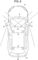
- FIG. 2 it is possible to arrange a right-left pair of front cameras 16, 16 at a front windshield 15 to recognize an object at each of the center, right, and left in front of an automobile 14, and to arrange a right-left pair of rear cameras 18, 18 at lower sections of right-left door mirrors 17, 17 to recognize an object at the lateral rear.
- an all-direction camera system by adding another camera to the cameras described above.
- a radar sensor 20 for example, being a millimeter-wave radar sensor, a micrometer-wave radar sensor, a laser radar sensor, an infrared radiation sensor, an ultrasonic sensor, or the like is arranged at the center of an upper section of a rear windshield 19.
- a radar sensor similar to the above may be arranged at a front center (e.g., at a radiator frame or under a hood) of the automobile 14.
- a center rear camera may be arranged at the rear center of the automobile 14 instead of or in addition to the radar sensor 20.
- speakers 13 of the stereo audio system 6 are arranged in the cabin each at the right and left of the front and rear, four in total. The number and location of the speakers 13 can be varied variously.
- Road map information is stored in advance in the automatic driving information storing unit 4, the road map information being necessary for selecting a travel route to a destination or changing the travel route if required and being necessary for travelling with automatic driving along the determined travel route, such as road maps, lane information, and traffic rules such as regulation speeds and traffic signs.
- a reference data file including data of images or shape features of various objects may be stored in the automatic driving information storing unit 4, the reference data file being used for detecting and recognizing, as objects, vehicles such as automobiles and pedestrians existing around the own vehicle from the information obtained by the information input unit 3.
- the automatic driving controller 2 is structured with a microcomputer that includes a CPU, a ROM, and a RAM.
- the CPU executes a program stored in the ROM for performing automatic driving of an automobile.
- the automatic driving controller 2 computes a travel route to the destination and proposes one or more candidates of the travel route.
- the automatic driving controller 2 controls the accelerating system 7, the steering system 8, the braking system 9, and the indicating system 10 in accordance with the travel route, and automatic driving is started.
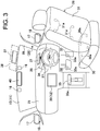
- FIG. 3 is a schematic view of a dashboard 25, a driver's seat 26, and surroundings thereof in the automobile 14 on which the automatic driving system 1 is mounted.
- a face image camera 28 is attached to the dashboard 25 just above an instrument panel 27 in front of the driver's seat 26. It is also possible that the face image camera 28 is arranged at a front pillar 29 closer to the driver's seat 26 (i.e., at the right front pillar on a vehicle with the steering wheel on the right side as in the present embodiment).
- the face image camera 28 is for capturing a face image of a driver at the driver's seat 26.
- the face image camera 28 is configured of a CMOS image sensor or a CCD image sensor. It is preferable that appropriate lighting equipment is arranged for the face image camera 28 so that capturing can be clearly performed with sufficient sensitivity even under a dark environment such as at night.
- a near-infrared LED or the like may be used as such a lighting equipment so as not to disturb driving for a driver.
- the captured face image data of the driver is input to the information input unit 3 of the automatic driving system 1 and is transmitted to the driver's state determining unit 22 of the automatic driving controller 2.
- the driver's state determining unit 22 determines a degree of arousal of the driver, that is, a degree of sleepiness being whether or not the driver is asleep.
- the driver's state determining unit 22 extracts, from the face image data, biometric information such as a degree of eye-opening (i.e., eye opening degree), a blinking behavior (e.g., the number of times and a duration of instantaneous opening-closing of eyes), variation of a pupil diameter, eye motion, an eye-closed duration and a ratio thereof, indications regarding driver eye behaviors, a position of the head, and posture and variation thereof.
- biometric information such as a degree of eye-opening (i.e., eye opening degree), a blinking behavior (e.g., the number of times and a duration of instantaneous opening-closing of eyes), variation of a pupil diameter, eye motion, an eye-closed duration and a ratio thereof, indications regarding driver eye behaviors, a position of the head, and posture and variation thereof.
- Body pressure sensors 30a, 31a each being configured of a plurality of pressure-sensitive elements are embedded in the driver's seat 26 at a seat face 30 and a seat back 31.
- a pressure-sensitive element is arranged at each of four diagonal positions of each of the seat face 30 and the seat back 31 as the body pressure sensors 30a, 31a.
- the number and/or location of the pressure-sensitive elements may be variously varied.
- the body pressure sensor 30a, 31a detects body pressure data including driver's weight and variation thereof exerted respectively on the seat face 30 and the seat back 31 and inputs the body pressure data to the information input unit 3 of the automatic driving system 1.
- the information input unit 3 transmits the received body pressure data to the driver's state determining unit 22 of the automatic driving controller 2.
- the driver's state determining unit 22 extracts periodical variation of body pressure from the body pressure data and detects the number of breathing of the driver within a specific period of time. Further, the driver's state determining unit 22 extracts body pressure distribution, and a barycentric position and variation thereof at the seat face 30 and the seat back 31 and detect driving posture of the driver and variation thereof.
- the driver's state determining unit 22 determines an arousal state of the driver, that is, whether the driver is aroused to a degree that manual driving can be performed or is asleep, and a degree of sleepiness. It is not necessary to use the whole biometric information described above. It is simply required to extract items necessary and sufficient for determining the arousal state of the driver. For example, only either the face image data or the body pressure data may be used while eliminating the face image camera 28 or the body pressure sensors 30a, 31a.
- Pressure-sensitive sensors 32a, 33a, 34a, 35a are arranged respectively at a brake pedal 32, an acceleration pedal 33, and a steering wheel 34 that are located in front of the driver's seat 26, and at a shift lever 35 located on a passenger's seat side of the driver's seat 26.
- the pressure-sensitive sensors 32a to 35a are activated by being exerted with predetermined pressure respectively.
- the pressure-sensitive sensors 32a to 35a detect operational state data such as whether or not a driver's foot is placed on the brake pedal 32 or the acceleration pedal 33, whether or not the steering wheel 34 is held by the driver, and whether or not the shift lever 35 is held by the driver.
- a plurality of the pressure-sensitive sensors 34a are arranged at positions in the circumferential direction of the steering wheel 34 to be capable of detecting that the steering wheel 34 is held by both hands.
- the operational state data detected by the respective pressure-sensitive sensors 32a to 35a is input to the information input unit 3 of the automatic driving system 1 and transmitted from the information input unit 3 to the driver's state determining unit 22 of the automatic driving controller 2.
- the driver's state determining unit 22 determines, from the operational data, whether the driver is in a state of being capable of promptly performing manual driving or whether the driver is ready therefor. For example, in a state that a data signal from the pressure-sensitive sensor 34a is on and the steering wheel 34 is held by the driver, it is determined that the driver is in a state of being capable of performing steering operation. In a state that a data signal from the pressure-sensitive sensor 32a or 33a is on, it is determined that the driver is in a state of being capable of operating the brake pedal 32 or the acceleration pedal 33. In a state that a data signal from the pressure-sensitive sensor 35a is on in addition to the on signal from the steering wheel 34 and the brake pedal 32 or the acceleration pedal 33, it can be determined that the driver is in a state of being capable of promptly performing manual driving.
- a head-up display (HUD) device 37 is arranged at the upper section of the dashboard 25 as a first display device 11 to project an image on the front windshield 15.
- the HUD device 37 may be assembled in the dashboard 25.
- the HUD device 37 may be arranged on an upper face of the dashboard 25 or at a position of a sun visor 38 at a ceiling of a driver's seat. Further, the HUD device 37 may be arranged so that the projecting can be performed from a plurality of positions of the above and/or others.
- HUD devices having a variety of structures are developed and used, such as a type in which a front windshield functions as a screen and a type in which a display image is projected on a transparent screen arranged between a front windshield and eyes of an occupant or arranged on a surface of a front windshield.
- An HUD device of the present invention may have any structure and any configuration that have been known.
- a monitor device 39 as the second display device 12 is integrally assembled in the dashboard 25 (i.e., in-dash) approximately at the front center of the dashboard 25.
- the monitor device may be attached on the dashboard 25 (i.e., on-dash).
- a rearview mirror 40 attached to an upper center part of the front windshield 15 to function as a third display device of the image display system 5.
- data indicating travel behaviors of the vehicle are input respectively from the accelerating system 7, the steering system 8, and the braking system 9 during automatic driving to the information input unit 3 and are transmitted to the travel behavior determining unit 21 of the automatic driving controller 2.
- the travel behavior determining unit 21 can determine whether the vehicle is accelerating or decelerating, whether the acceleration or deceleration is quick or slow (i.e., degree of acceleration or deceleration), whether steering operation is stable or under operation, and the like.
- the travel behavior determining unit 21 receives information regarding a travel route set by the automatic driving controller 2 for automatic driving, and travel environments of the own vehicle or traffic situations input through the information input unit 3 from the front camera 16, the rear camera 18, and the radar sensor 20.
- the travel behavior determining unit 21 determines whether safe driving can be maintained and ensured even when the vehicle during automatic driving is immediately switched to manual driving. For example, if it is suddenly switched to manual driving during steering operation with automatic driving of the vehicle, there arises a fear that strong feeling of tension is created and advanced steering operation is required for the driver. Further, if it is switched to manual driving during acceleration or deceleration with automatic driving, there arises a fear that vehicle speed becomes unstable. Accordingly, in such cases, shifting to manual driving should not be performed until automatic driving becomes into a stable travel state (e.g., a state of travelling approximately at a constant speed approximately linearly or on a gentle curve). Naturally, in a state of emergency such as a case that serious danger is closing, it should be switched to manual driving immediately. Such switching can be performed by overriding by the driver.
- the drive mode switching control unit 23 controls switching from an automatic drive mode to a manual drive mode. Such drive mode switching control is performed while providing the first priority to safe driving. When it is determined that safe driving cannot be ensured, the drive mode switching may be cancelled (automatic driving is maintained) or the vehicle may be stopped safely.
- the first case is a case of being determined that the automatic drive mode is difficult or inappropriate to be maintained for some reason during automatic driving. Examples of the above include a case that the automatic driving controller 2 determines that travel environments or traffic situations around the own vehicle are not suitable for automatic driving based on the images captured by the front camera 16 or the rear camera 18 or the information input through the information input unit 3 from the radar sensor 20.
- the second case is a case that the switching is to be performed positively and intentionally by the driver.
- step St1 Description will be provided on the first case of the switching control from the automatic drive mode to the manual drive mode according to the automatic driving system 1 of the present embodiment with reference to flowcharts of FIGs. 4 to 6 .
- the drive mode switching control unit 23 notifies in advance the driver of releasing of automatic driving and shifting to manual driving (step St1).
- Such a notification of drive mode shifting is provided by displaying images of texts, animation and/or the like at the first and/or second display devices 11, 12 using the image display system 5 and concurrently issuing an audio message and/or an alert sound from the respective speakers 13 using the stereo audio system 6.
- step St2 determines the state of the driver as described above (step St2).
- the determination in step St2 is performed in two stages as illustrated in the flowchart of FIG. 5 .
- the driver's state determining unit 22 determines an arousal state of the driver based on the data transmitted from the face image camera 28 and/or the body pressure sensors 30a, 31a at the driver's seat 26 (step St21). If the driver is in an aroused state, readiness of the driver is determined based on the data from the respective pressure-sensitive sensors 32a to 35a (step St22). If the driver is ready for shifting to manual driving, it proceeds to the next step St3 ( FIG. 4 ).
- step St21 of FIG. 5 if the driver is not in the aroused state, the drive mode switching control unit 23 maintains automatic driving (step St23). Next, the drive mode switching control unit 23 determines whether or not the last determination in step St21 is the first determination (step St24). If the determination is a repeated determination, it proceeds to step St5 in FIG. 4 and cancels switching to the manual drive mode.
- the drive mode switching control unit 23 performs a process to encourage arousal of the driver (step St25).
- the process is performed, for example, by issuing an audio message and/or an alert sound more loudly from the respective speakers 13 using the stereo audio system 6 and/or by displaying with lighting or blinking at the first and second display devices 11, 12 so that the alert image is more striking.
- it returns to step St21 and the arousal state of the driver is determined again by the drive's state determining unit 22.
- the drive mode switching control unit 23 perform providing a notification (or alert) to encourage the driver to confirm readiness for shifting to manual driving (step St26).
- the confirmation notification is provided by displaying images of texts, animation and/or the like at the first and/or second display devices 11, 12 using the image display system 5 and/or issuing an audio message from the respective speakers 13 using the stereo audio system 6.
- the driver's state determining unit 22 determines that the driver is ready for manual driving even if the data signal from the pressure-sensitive sensor 35a is not on.
- the drive mode switching control unit 23 cancels the confirmation notification provided by the image display system 5 and/or the stereo audio system 6 (step St27).
- step St26 the drive mode switching control unit 23 provides an alarm to the driver to be ready for operating the steering wheel 34, or the brake pedal 32 and the acceleration pedal 33, data signals of the pressure-sensitive sensors of which are off. Such alarm is provided as described above using the image display system 5 and/or the stereo audio system 6.
- the data signal from the steering wheel 34 is important. This is because steering operation is absolutely necessary for a travelling vehicle to ensure safe travelling. Accordingly, a state that the data signal from the steering wheel 34 is on may be essential as an absolute requirement for determination that the driver is ready for manual driving.
- the travel behavior determining unit 21 determines a travel behavior of the vehicle (step St3).
- the travel behavior is determined based on whether the vehicle is in a state of being shiftable to manual driving while maintaining safe driving, at the time of travelling with automatic driving, based on a safety degree of steering operation and a state of acceleration and deceleration as well as travel environments of the own vehicle and/or traffic situations (step S31).
- the drive mode switching control unit 23 performs switching to the manual drive mode as proceeding to step St4 in FIG. 4 .
- step St31 if the travel behavior of the vehicle is determined as not being in the shiftable state to manual driving, the drive mode switching control unit 23 determines whether or not the last determination in step S31 is the first determination (step St32). If the last determination in step S31 is a repeated determination, the drive mode switching control unit 23 cancels switching to the manual drive mode as proceeding to step St5 in FIG. 4 .
- step St32 if the last determination in step St31 is the first determination, the drive mode switching control unit 23 maintains automatic driving (step St33) and waits until it turns into a shiftable state to manual driving. Then, after a specific period of time has passed (step St34) from the first determination (step St31), the travel behavior determining unit 21 determines a travel behavior of the vehicle again as returning to step St31.
- step St4 the drive mode switching control unit 23 releases the automatic drive mode with the automatic driving system 1 and performs switching to the manual drive mode. At the same time, the drive mode switching control unit 23 notifies the driver of having shifted to the manual drive mode using the image display system 5 and/or the stereo audio system 6.
- step St5 when the automatic driving controller 2 has determined that automatic driving is possible to be maintained, automatic driving is continuously maintained.
- the automatic driving controller 2 when the automatic driving controller 2 has determined that automatic driving is difficult to be maintained, the automatic driving controller 2 causes the own vehicle to be stopped at a safe position with automatic driving.
- switching to manual driving based on driver's own intention is performed by the driver operating a button or a switch for manual driving confirmation included in the automatic driving system 1.
- switching to manual driving is performed by the driver overriding steering operation, accelerating operation, or a braking operation.
- the driver is not suited for manual driving due to poor health caused by illness, injury, alcohol drinking, depressed consciousness, or the like.
- the manual confirmation button is operated by mistake or driving operation is overrode, caused by carelessness or incorrect operation of the driver or another occupant, or another incidental reason.
- switching to manual driving is performed after determining a driver's state and determining a travel behavior of the vehicle by executing necessary steps among the abovementioned steps in relation to FIGs. 4 to 6 .
- the automatic driving system 1 is provided with the manual driving confirmation button.
- the automatic driving system 1 proceeds to a step (corresponding to step St22 of FIG. 5 ) in which readiness of the driver is determined with the driver deemed to be in an aroused state.
- the automatic driving system 1 maintains automatic driving until the readiness of the driver is determined.
- Determination of the readiness of the driver is performed by the driver's state determining unit 22 based on data signals from the pressure-sensitive sensors 34a, 32a, 33a, 35a of the steering wheel 34, the brake pedal 32, the acceleration pedal 33, and the transmission lever 35. For example, when the data signal from the steering wheel 34 is on, and concurrently, the data signal from one or more of the brake pedal 32, the acceleration pedal 33, and the transmission lever 35 is on, the driver is determined as being ready for manual driving.
- the automatic driving system 1 Even if the data signal from the steering wheel 34 is on, when the data signals from the brake pedal 32, the acceleration pedal 33, and the transmission lever 35 are off, the automatic driving system 1 provides an alarm to the driver to be ready for operating the brake pedal 32, the acceleration pedal 33, and the transmission lever 35 using the image display system 5 and/or the stereo audio system 6 as described above. In contrast, when one or more of the data signals from the brake pedal 32, the acceleration pedal 33, and the transmission lever 35 is on while the data signal from the steering wheel 34 is off, the automatic driving system 1 provides an alarm similarly to the driver to be ready for operating the steering wheel 34 using the image display system 5 and/or the stereo audio system 6. As a result of such alarms, when two or more operations including the steering wheel operation are active, the driver is determined as being ready for manual driving.
- the travel behavior determining unit 21 determines a travel behavior of the vehicle. The determination can be performed similarly to step St3 of FIG. 4 and the respective steps of FIG. 6 .
- the drive mode switching control unit 23 performs switching to the manual drive mode. Switching to the manual drive mode can be notified to the driver by the drive mode switching control unit 23 using the image display system 5 and/or the stereo audio system 6. Since the driver has been deemed to be in an aroused state as described above, the notification is important for causing the driver to recognize switching to manual driving.
- the automatic driving system 1 does not include the manual driving confirmation button and any of the face image camera 28, the body pressure sensors 30a, 31a, and other sensors for determining the arousal state of the driver.
- switching from the automatic drive mode to the manual drive mode is performed generally in two cases. One is a case that the automatic driving system 1 determines that maintaining the automatic drive mode is difficult or inadequate for some reason during automatic driving. The other is a case that the switching is to be performed positively and intentionally by the driver.
- the drive mode switching control unit 23 notifies in advance the driver of releasing of automatic driving and shifting to manual driving.
- a notification of drive mode shifting is provided by displaying an appropriate message at the first and/or second display devices 11, 12 using the image display system 5 and/or issuing an audio message or an alert sound from the respective speakers 13 using the stereo audio system 6.
- the shifting process to manual driving to be performed after the notification to the driver is substantially the same for both the cases of switching by the automatic driving system 1 and positive switching based on driver's intention. In the following, description will be performed commonly as the shifting step for both the cases.
- the automatic driving system 1 determines the arousal state and readiness of the driver based on data signals from the pressure-sensitive sensors 34a, 32a, 33a, 35a of the steering wheel 34, the brake pedal 32, the acceleration pedal 33, and the transmission lever 35. For example, when data signals from two or more of the steering wheel 34, the brake pedal 32, the acceleration pedal 33, and the transmission lever 35 are concurrently on, it is determined that the driver is deemed to be in an aroused state. The determination is performed by the driver's state determining unit 22 of the automatic driving controller 2.
- the automatic driving system 1 determines readiness of the driver.
- the automatic driving system 1 maintains automatic driving until the arousal state and the readiness of the driver are determined.
- the driver when the driver is determined as being in an aroused state, it is normally considered that the driver is ready for manual driving.
- the data signal from the steering wheel 34 when the data signal from the steering wheel 34 is on, and concurrently, the data signal from one or more of the brake pedal 32, the acceleration pedal 33, and the transmission lever 35 is on, it is possible that the driver is determined as being ready for manual driving. In this case, the arousal state and the readiness of the driver are concurrently determined.
- the automatic driving system 1 When one or more of the data signals from the brake pedal 32, the acceleration pedal 33, and the transmission lever 35 is on while the data signal from the steering wheel 34 is off, the automatic driving system 1 provides an alarm to the driver to be ready for operating the steering wheel 34 using the image display system 5 and/or the stereo audio system 6. As a result of such alarms, when two or more operations including the steering operation are active, the driver is determined as being ready for manual driving.
- detection of steering operation by the driver is basically required for determining readiness for manual driving. This is because steering operation is absolutely necessary for a travelling vehicle to ensure safe travelling.
- operational states of the steering wheel 34, the brake pedal 32, the acceleration pedal 33, and the transmission lever 35 are treated as equivalent as the above in determining readiness of the driver for manual driving.
- the travel behavior determining unit 21 determines a travel behavior of the vehicle. The determination can be performed similarly to step St3 of FIG. 4 and the respective steps of FIG. 6 .
- the drive mode switching control unit 23 performs switching to the manual drive mode. Switching to the manual drive mode is notified to the driver by the drive mode switching control unit 23 using the image display system 5 and/or the stereo audio system 6. Since the driver has been deemed to be in an aroused state as described above, the notification is important for causing the driver to recognize switching to manual driving.
- the drive's state determining unit 22 determines that the arousal state and/or the readiness of the driver are not suitable for manual driving with the methods respectively described in the embodiments
- Examples of the above include a case that the driver does not perform driving operation, that is, steering operation, accelerating operation, or braking operation even after a specific period of time has passed from the switching to manual driving.
- the automatic driving controller 2 determines that automatic driving is difficult to be maintained, it is also possible to cause the vehicle to be stopped at a safe position.
- the automatic driving system 1 whose automatic degree is Level 3 to perform all of accelerating, steering, and braking of an automobile.
- the automatic driving system of the present invention can be similarly applied as well to a system of Level 1 to automatically perform any of accelerating, steering, and braking, a system of Level 2 to automatically perform a plurality of operations among accelerating, steering, and braking, and a system of Level 4 to continue automatic driving even in a case that an occupant does not respond to a drive mode switching request from the system.
Landscapes
- Engineering & Computer Science (AREA)
- Automation & Control Theory (AREA)
- Transportation (AREA)
- Mechanical Engineering (AREA)
- Physics & Mathematics (AREA)
- Human Computer Interaction (AREA)
- General Physics & Mathematics (AREA)
- Chemical & Material Sciences (AREA)
- Combustion & Propulsion (AREA)
- Aviation & Aerospace Engineering (AREA)
- Radar, Positioning & Navigation (AREA)
- Remote Sensing (AREA)
- Mathematical Physics (AREA)
- Traffic Control Systems (AREA)
- Control Of Driving Devices And Active Controlling Of Vehicle (AREA)
- Instrument Panels (AREA)
Applications Claiming Priority (2)
| Application Number | Priority Date | Filing Date | Title |
|---|---|---|---|
| JP2015149501A JP6552316B2 (ja) | 2015-07-29 | 2015-07-29 | 車輌の自動運転システム |
| PCT/JP2016/069805 WO2017018133A1 (ja) | 2015-07-29 | 2016-07-04 | 車輌の自動運転システム |
Publications (3)
| Publication Number | Publication Date |
|---|---|
| EP3330148A1 EP3330148A1 (en) | 2018-06-06 |
| EP3330148A4 EP3330148A4 (en) | 2019-02-20 |
| EP3330148B1 true EP3330148B1 (en) | 2020-10-14 |
Family
ID=57884508
Family Applications (1)
| Application Number | Title | Priority Date | Filing Date |
|---|---|---|---|
| EP16830238.8A Active EP3330148B1 (en) | 2015-07-29 | 2016-07-04 | Automatic driving system for vehicles |
Country Status (5)
| Country | Link |
|---|---|
| US (1) | US20190155279A1 (ja) |
| EP (1) | EP3330148B1 (ja) |
| JP (1) | JP6552316B2 (ja) |
| CN (1) | CN107848538A (ja) |
| WO (1) | WO2017018133A1 (ja) |
Families Citing this family (94)
| Publication number | Priority date | Publication date | Assignee | Title |
|---|---|---|---|---|
| KR20170015113A (ko) * | 2015-07-30 | 2017-02-08 | 삼성전자주식회사 | 자율 주행 차량을 제어하는 장치 및 방법 |
| JP6508072B2 (ja) * | 2016-01-26 | 2019-05-08 | 株式会社デンソー | 報知制御装置及び報知制御方法 |
| CA3025634A1 (en) * | 2016-05-27 | 2017-11-30 | Nissan Motor Co., Ltd. | Driving control method and driving control apparatus |
| US10640117B2 (en) * | 2016-08-17 | 2020-05-05 | Allstate Insurance Company | Driving cues and coaching |
| KR101951565B1 (ko) * | 2016-10-18 | 2019-02-22 | 서울대학교산학협력단 | 자세 및 작업 감지를 통한 안구 건조증 경고 시스템 |
| JP6759991B2 (ja) * | 2016-11-07 | 2020-09-23 | アイシン精機株式会社 | 乗員検知方法及び乗員検知装置 |
| JP6849415B2 (ja) * | 2016-11-30 | 2021-03-24 | トヨタ自動車株式会社 | 自動運転システム |
| WO2018142458A1 (ja) * | 2017-01-31 | 2018-08-09 | 三菱電機株式会社 | 自動運転制御装置 |
| JP6631567B2 (ja) * | 2017-03-10 | 2020-01-15 | オムロン株式会社 | 自動運転支援装置、方法及びプログラム |
| JP2018149862A (ja) * | 2017-03-10 | 2018-09-27 | オムロン株式会社 | 運転モード切替制御装置、方法およびプログラム |
| US20190370580A1 (en) * | 2017-03-14 | 2019-12-05 | Omron Corporation | Driver monitoring apparatus, driver monitoring method, learning apparatus, and learning method |
| JP6627811B2 (ja) * | 2017-03-14 | 2020-01-08 | オムロン株式会社 | 集中度判定装置、集中度判定方法及び集中度判定のためのプログラム |
| JP2018167623A (ja) * | 2017-03-29 | 2018-11-01 | テイ・エス テック株式会社 | 車両制御システム |
| JP2018180594A (ja) * | 2017-04-03 | 2018-11-15 | 株式会社デンソー | 走行支援装置 |
| JP6631577B2 (ja) * | 2017-04-05 | 2020-01-15 | 株式会社デンソー | 運転交代制御システム、運転交代制御プログラム、及び運転交代制御方法 |
| KR102287316B1 (ko) * | 2017-04-14 | 2021-08-09 | 현대자동차주식회사 | 자율주행 제어 장치 및 방법, 그리고 차량 시스템 |
| JP7005933B2 (ja) * | 2017-05-09 | 2022-01-24 | オムロン株式会社 | 運転者監視装置、及び運転者監視方法 |
| JP6948559B2 (ja) * | 2017-05-09 | 2021-10-13 | オムロン株式会社 | 運転者監視装置、及び運転者監視方法 |
| CN108944950B (zh) * | 2017-05-19 | 2020-09-08 | 上海汽车集团股份有限公司 | 一种汽车驾驶模式的切换控制方法和装置 |
| JP6920112B2 (ja) * | 2017-06-15 | 2021-08-18 | 株式会社デンソーテン | 運転支援装置および運転支援方法 |
| US20200117192A1 (en) * | 2017-06-15 | 2020-04-16 | Hitachi Automotive Systems, Ltd. | Travel Control Device |
| WO2019016910A1 (ja) * | 2017-07-20 | 2019-01-24 | 株式会社トヨタマップマスター | 新規道路推定支援装置、新規道路推定支援方法、コンピュータプログラム及びコンピュータプログラムを記録した記録媒体 |
| JP2019034576A (ja) * | 2017-08-10 | 2019-03-07 | オムロン株式会社 | 運転者状態把握装置、運転者状態把握システム、及び運転者状態把握方法 |
| JP6909857B2 (ja) * | 2017-08-29 | 2021-07-28 | 株式会社日立製作所 | 車両制御装置 |
| JP7044295B2 (ja) * | 2017-10-02 | 2022-03-30 | 株式会社デンソーアイティーラボラトリ | 自動運転制御装置、自動運転制御方法、およびプログラム |
| CN108297877B (zh) | 2017-10-10 | 2019-08-13 | 腾讯科技(深圳)有限公司 | 车辆控制方法、系统及装置 |
| JP6652539B2 (ja) * | 2017-10-12 | 2020-02-26 | 矢崎総業株式会社 | 自動運転時情報伝達方法および車載情報提示装置 |
| KR101999541B1 (ko) * | 2017-11-27 | 2019-10-01 | (주)에스더블유엠 | 자율주행 차량의 오버라이드 제어 방법 및 장치 |
| JP2019119281A (ja) * | 2017-12-28 | 2019-07-22 | 株式会社Jvcケンウッド | 投影制御装置、ヘッドアップディスプレイ装置、投影制御方法およびプログラム |
| KR102167009B1 (ko) * | 2018-01-10 | 2020-10-16 | 순천향대학교 산학협력단 | 차량의 제어방식 자동 전환 장치 |
| JP6637091B2 (ja) * | 2018-03-07 | 2020-01-29 | 本田技研工業株式会社 | 車両制御装置 |
| JP7066463B2 (ja) * | 2018-03-15 | 2022-05-13 | 本田技研工業株式会社 | 走行支援システムおよび車両の制御方法 |
| JP2019156247A (ja) * | 2018-03-15 | 2019-09-19 | 本田技研工業株式会社 | シート装置 |
| CN108749713A (zh) * | 2018-04-02 | 2018-11-06 | 北京新能源汽车股份有限公司 | 车内滞留人员安全控制方法、装置及设备 |
| JP7133337B2 (ja) * | 2018-04-10 | 2022-09-08 | 本田技研工業株式会社 | 車両制御装置、車両制御方法、及びプログラム |
| EP3552902A1 (en) | 2018-04-11 | 2019-10-16 | Hyundai Motor Company | Apparatus and method for providing a driving path to a vehicle |
| US10843710B2 (en) | 2018-04-11 | 2020-11-24 | Hyundai Motor Company | Apparatus and method for providing notification of control authority transition in vehicle |
| EP3552909A1 (en) * | 2018-04-11 | 2019-10-16 | Hyundai Motor Company | Apparatus and method for managing control authority transition in vehicle |
| US11597403B2 (en) | 2018-04-11 | 2023-03-07 | Hyundai Motor Company | Apparatus for displaying driving state of vehicle, system including the same and method thereof |
| US11334067B2 (en) | 2018-04-11 | 2022-05-17 | Hyundai Motor Company | Apparatus and method for providing safety strategy in vehicle |
| US11173910B2 (en) | 2018-04-11 | 2021-11-16 | Hyundai Motor Company | Lane change controller for vehicle system including the same, and method thereof |
| EP3569460B1 (en) | 2018-04-11 | 2024-03-20 | Hyundai Motor Company | Apparatus and method for controlling driving in vehicle |
| US11351989B2 (en) | 2018-04-11 | 2022-06-07 | Hyundai Motor Company | Vehicle driving controller, system including the same, and method thereof |
| US10836394B2 (en) | 2018-04-11 | 2020-11-17 | Hyundai Motor Company | Apparatus and method for lane change control |
| US11548509B2 (en) | 2018-04-11 | 2023-01-10 | Hyundai Motor Company | Apparatus and method for controlling lane change in vehicle |
| US11084490B2 (en) | 2018-04-11 | 2021-08-10 | Hyundai Motor Company | Apparatus and method for controlling drive of vehicle |
| US11077854B2 (en) | 2018-04-11 | 2021-08-03 | Hyundai Motor Company | Apparatus for controlling lane change of vehicle, system having the same and method thereof |
| ES2889930T3 (es) | 2018-04-11 | 2022-01-14 | Hyundai Motor Co Ltd | Aparato y método para el control para habilitar un sistema autónomo en un vehículo |
| US11084491B2 (en) | 2018-04-11 | 2021-08-10 | Hyundai Motor Company | Apparatus and method for providing safety strategy in vehicle |
| EP3552901A3 (en) | 2018-04-11 | 2020-04-29 | Hyundai Motor Company | Apparatus and method for providing safety strategy in vehicle |
| JP6848927B2 (ja) * | 2018-04-13 | 2021-03-24 | 株式会社デンソー | 自動運転車両の情報提供装置 |
| CN108674415B (zh) * | 2018-04-18 | 2021-04-02 | 北京汽车集团有限公司 | 车辆控制方法和装置 |
| JP7273031B2 (ja) * | 2018-04-20 | 2023-05-12 | ソニーセミコンダクタソリューションズ株式会社 | 情報処理装置、移動装置、情報処理システム、および方法、並びにプログラム |
| US10858004B2 (en) * | 2018-04-23 | 2020-12-08 | Ford Global Technologies, Llc | Methods and systems for improving automatic engine stopping and starting |
| JP2019191893A (ja) * | 2018-04-24 | 2019-10-31 | 本田技研工業株式会社 | 車両制御装置及びプログラム |
| CN108776472A (zh) * | 2018-05-17 | 2018-11-09 | 驭势(上海)汽车科技有限公司 | 智能驾驶控制方法及系统、车载控制设备和智能驾驶车辆 |
| US11937538B2 (en) * | 2018-06-21 | 2024-03-26 | Kubota Corporation | Work vehicle and grass mowing machine |
| CN108919807A (zh) * | 2018-07-17 | 2018-11-30 | 济南浪潮高新科技投资发展有限公司 | 一种自动驾驶系统及方法 |
| CN108974013B (zh) * | 2018-07-19 | 2019-12-13 | 合肥工业大学 | 基于方向盘握力的人机权限切换方法 |
| JP7216505B2 (ja) * | 2018-09-11 | 2023-02-01 | 株式会社Subaru | 車両の走行制御システム |
| CN111216740A (zh) * | 2018-11-08 | 2020-06-02 | 株式会社万都 | 驾驶员辅助设备及其控制方法以及驾驶员辅助系统 |
| US20210387640A1 (en) * | 2018-11-13 | 2021-12-16 | Sony Group Corporation | Information processing apparatus, information processing method, and program |
| US11144052B2 (en) | 2018-12-07 | 2021-10-12 | Toyota Research Institute, Inc. | Readiness and identification by gaze and/or gesture pattern detection |
| JP7188212B2 (ja) * | 2019-03-22 | 2022-12-13 | トヨタ自動車株式会社 | 車両走行制御装置 |
| JP7273577B2 (ja) * | 2019-03-27 | 2023-05-15 | 株式会社Subaru | 車両の制御装置、車両の制御方法及び車両の制御システム |
| JP7154177B2 (ja) * | 2019-03-29 | 2022-10-17 | 本田技研工業株式会社 | 制御装置、制御方法及びプログラム |
| JP2020168918A (ja) * | 2019-04-02 | 2020-10-15 | 株式会社ジェイテクト | 操舵装置 |
| DE102019204892A1 (de) * | 2019-04-05 | 2020-10-08 | Robert Bosch Gmbh | Verfahren und Steuergerät zum Erkennen einer Müdigkeit eines Fahrers für ein Fahrassistenzsystem für ein Fahrzeug |
| WO2020255287A1 (ja) * | 2019-06-19 | 2020-12-24 | 三菱電機株式会社 | 自動運転支援装置、自動運転支援システムおよび自動運転支援方法 |
| US11173835B2 (en) | 2019-07-01 | 2021-11-16 | International Business Machines Corporation | Notifying passengers of imminent vehicle braking |
| JP7047821B2 (ja) | 2019-07-18 | 2022-04-05 | トヨタ自動車株式会社 | 運転支援装置 |
| KR20210011557A (ko) * | 2019-07-22 | 2021-02-02 | 현대자동차주식회사 | 자율 주행 제어 장치, 그를 포함한 시스템 및 그 방법 |
| CN110576864A (zh) * | 2019-08-15 | 2019-12-17 | 中国第一汽车股份有限公司 | 驾驶模式的控制方法、装置、车辆及存储介质 |
| JP2021043571A (ja) * | 2019-09-09 | 2021-03-18 | ソニーセミコンダクタソリューションズ株式会社 | 情報処理装置、移動装置、情報処理システム、および方法、並びにプログラム |
| KR20210051054A (ko) * | 2019-10-29 | 2021-05-10 | 현대자동차주식회사 | 뇌파 신호를 이용한 모빌리티 탑승자의 승차감 판단 장치 |
| CN112744175A (zh) * | 2019-10-30 | 2021-05-04 | 广州汽车集团股份有限公司 | 一种安全气囊系统及其控制方法 |
| CN110861653A (zh) * | 2019-11-26 | 2020-03-06 | 北京明略软件系统有限公司 | 一种提醒方法、装置、车辆、设备和存储介质 |
| CN110901643A (zh) * | 2019-12-05 | 2020-03-24 | 大陆泰密克汽车系统(上海)有限公司 | 自动驾驶主动接管系统及方法 |
| WO2021132134A1 (ja) * | 2019-12-25 | 2021-07-01 | 日立Astemo株式会社 | 車両運動制御装置、車両運動制御方法及び車両運動制御システム |
| JP6979091B2 (ja) * | 2020-01-29 | 2021-12-08 | 本田技研工業株式会社 | 車両制御装置、車両、車両制御方法及びプログラム |
| JP7306284B2 (ja) * | 2020-01-31 | 2023-07-11 | トヨタ自動車株式会社 | 車両および車両制御インターフェース |
| JP7264086B2 (ja) | 2020-02-27 | 2023-04-25 | トヨタ自動車株式会社 | 車両制御装置及び車両制御方法 |
| JP7140154B2 (ja) * | 2020-03-04 | 2022-09-21 | トヨタ自動車株式会社 | 車両制御装置 |
| WO2021200122A1 (ja) * | 2020-03-31 | 2021-10-07 | 株式会社デンソー | 提示制御装置および提示制御プログラム |
| CN113494921B (zh) * | 2020-04-01 | 2023-09-22 | 华为技术有限公司 | 自动驾驶方法及装置 |
| CN111469666A (zh) * | 2020-04-29 | 2020-07-31 | 徐州徐工矿业机械有限公司 | 一种电传动矿用自卸车自动电缓行系统及方法 |
| KR20210146488A (ko) * | 2020-05-26 | 2021-12-06 | 현대자동차주식회사 | 자율 주행 제어 방법 및 장치 |
| CN114380239A (zh) * | 2020-10-22 | 2022-04-22 | 浙江中力机械股份有限公司 | 手自动切换装置 |
| CN113311744B (zh) * | 2021-05-13 | 2022-08-19 | 际络科技(上海)有限公司 | 一种自动驾驶的手动控制方法和装置 |
| CN113525404A (zh) * | 2021-07-26 | 2021-10-22 | 英博超算(南京)科技有限公司 | 一种可无缝切换的人机共驾车辆控制系统及其使用方法 |
| CN113830102B (zh) * | 2021-08-04 | 2023-09-29 | 深圳市智慧联芯科技有限公司 | 驾驶模式切换方法、装置、存储介质及计算机设备 |
| KR102592102B1 (ko) * | 2021-08-17 | 2023-10-23 | 한국자동차연구원 | 자율주행 제어권 전환에 대한 준비도 판단 장치 및 그 방법 |
| CN113844449A (zh) * | 2021-10-18 | 2021-12-28 | 安徽江淮汽车集团股份有限公司 | 基于多状态集成的巡航系统控制方法 |
| US11793434B1 (en) * | 2022-05-18 | 2023-10-24 | GM Global Technology Operations LLC | System to perform visual recognition and vehicle adaptation |
Family Cites Families (13)
| Publication number | Priority date | Publication date | Assignee | Title |
|---|---|---|---|---|
| US5469356A (en) * | 1994-09-01 | 1995-11-21 | Caterpillar Inc. | System for controlling a vehicle to selectively allow operation in either an autonomous mode or a manual mode |
| JP3590917B2 (ja) * | 1995-12-01 | 2004-11-17 | 本田技研工業株式会社 | 車両用運転予知制御装置 |
| JP3171119B2 (ja) * | 1995-12-04 | 2001-05-28 | トヨタ自動車株式会社 | 車両の自動運転制御装置 |
| JPH10309961A (ja) * | 1997-05-12 | 1998-11-24 | Toyota Motor Corp | 自動走行車両制御装置 |
| JPH1191397A (ja) * | 1997-09-22 | 1999-04-06 | Toyota Motor Corp | 自動走行車両制御装置 |
| JP3094100B1 (ja) * | 1999-03-26 | 2000-10-03 | 建設省土木研究所長 | 自動運転制御装置 |
| JP4946374B2 (ja) * | 2006-11-13 | 2012-06-06 | トヨタ自動車株式会社 | 自動運転車両 |
| JP5125745B2 (ja) * | 2008-05-12 | 2013-01-23 | トヨタ自動車株式会社 | 運転支援装置、運転支援方法 |
| JP2011118603A (ja) * | 2009-12-02 | 2011-06-16 | Clarion Co Ltd | 車両制御装置 |
| JP5493842B2 (ja) * | 2009-12-25 | 2014-05-14 | トヨタ自動車株式会社 | 走行支援装置 |
| FR2989047B1 (fr) * | 2012-04-05 | 2014-04-11 | Renault Sa | Systeme de commande de vehicule en mode autonome et vehicule comprenant un tel systeme de commande |
| DE102013010630A1 (de) * | 2013-06-25 | 2015-01-08 | Leopold Kostal Gmbh & Co. Kg | Vorrichtung und Verfahren zum wahlweisen Betreiben eines Kraftfahrzeugs in einem benutzergesteuerten oder einem automatischen Fahrbetriebsmodus |
| CN104064050B (zh) * | 2014-06-30 | 2015-12-30 | 科大讯飞股份有限公司 | 自动驾驶系统及方法 |
-
2015
- 2015-07-29 JP JP2015149501A patent/JP6552316B2/ja active Active
-
2016
- 2016-07-04 CN CN201680044248.5A patent/CN107848538A/zh active Pending
- 2016-07-04 EP EP16830238.8A patent/EP3330148B1/en active Active
- 2016-07-04 WO PCT/JP2016/069805 patent/WO2017018133A1/ja active Application Filing
- 2016-07-04 US US15/747,667 patent/US20190155279A1/en not_active Abandoned
Non-Patent Citations (1)
| Title |
|---|
| None * |
Also Published As
| Publication number | Publication date |
|---|---|
| JP6552316B2 (ja) | 2019-07-31 |
| CN107848538A (zh) | 2018-03-27 |
| WO2017018133A1 (ja) | 2017-02-02 |
| EP3330148A4 (en) | 2019-02-20 |
| US20190155279A1 (en) | 2019-05-23 |
| EP3330148A1 (en) | 2018-06-06 |
| JP2017030390A (ja) | 2017-02-09 |
Similar Documents
| Publication | Publication Date | Title |
|---|---|---|
| EP3330148B1 (en) | Automatic driving system for vehicles | |
| US11492017B2 (en) | Information presentation device and information presentation method | |
| JP7024806B2 (ja) | 情報提示装置 | |
| JP6342856B2 (ja) | 車両制御装置 | |
| JP6540663B2 (ja) | 車両システム | |
| US20180118223A1 (en) | Startup suggestion device and startup suggestion method | |
| JP2014019301A (ja) | 緊急退避装置 | |
| JP6705437B2 (ja) | 脇見判定装置、脇見判定方法及び脇見判定のためのプログラム | |
| JP5803832B2 (ja) | 緊急退避支援装置 | |
| US20170158054A1 (en) | In-vehicle control apparatus | |
| CN107303908A (zh) | 用于自动道路车辆安全停止的设备和方法 | |
| JP2018180594A (ja) | 走行支援装置 | |
| WO2014148025A1 (ja) | 走行制御装置 | |
| CN109649403A (zh) | 自动驾驶期间传达信息的方法和车辆信息呈现装置 | |
| JP6524129B2 (ja) | 運転支援装置 | |
| WO2018150676A1 (ja) | 運転切替支援装置、及び運転切替支援方法 | |
| JP2020164077A (ja) | 車両制御システム | |
| JP3890996B2 (ja) | 運転支援装置 | |
| WO2018150677A1 (ja) | 運転切替支援装置、及び運転切替支援方法 | |
| KR20190041328A (ko) | 자율주행 차량에서 수동주행 모드로의 전환 조건 | |
| JP2018154329A (ja) | 車載制御装置及び車載システム | |
| JP6398182B2 (ja) | 信号情報提示装置 | |
| EP3885195A1 (en) | System and method for providing visual guidance using light projection | |
| JP2005162189A (ja) | 運転支援方策決定方法および運転支援装置 | |
| JP2009042824A (ja) | 飲酒運転防止装置 |
Legal Events
| Date | Code | Title | Description |
|---|---|---|---|
| STAA | Information on the status of an ep patent application or granted ep patent |
Free format text: STATUS: THE INTERNATIONAL PUBLICATION HAS BEEN MADE |
|
| PUAI | Public reference made under article 153(3) epc to a published international application that has entered the european phase |
Free format text: ORIGINAL CODE: 0009012 |
|
| STAA | Information on the status of an ep patent application or granted ep patent |
Free format text: STATUS: REQUEST FOR EXAMINATION WAS MADE |
|
| 17P | Request for examination filed |
Effective date: 20180215 |
|
| AK | Designated contracting states |
Kind code of ref document: A1 Designated state(s): AL AT BE BG CH CY CZ DE DK EE ES FI FR GB GR HR HU IE IS IT LI LT LU LV MC MK MT NL NO PL PT RO RS SE SI SK SM TR |
|
| AX | Request for extension of the european patent |
Extension state: BA ME |
|
| RIN1 | Information on inventor provided before grant (corrected) |
Inventor name: TAYAMA, SHUICHI |
|
| RAP1 | Party data changed (applicant data changed or rights of an application transferred) |
Owner name: IMAGE CO., LTD. Owner name: TAYAMA, SHUICHI |
|
| DAV | Request for validation of the european patent (deleted) | ||
| DAX | Request for extension of the european patent (deleted) | ||
| A4 | Supplementary search report drawn up and despatched |
Effective date: 20190118 |
|
| RIC1 | Information provided on ipc code assigned before grant |
Ipc: B60W 40/04 20060101ALI20190114BHEP Ipc: B60W 30/00 20060101ALI20190114BHEP Ipc: B60W 40/06 20120101ALI20190114BHEP Ipc: G08G 1/16 20060101ALI20190114BHEP Ipc: B60W 50/12 20120101ALI20190114BHEP Ipc: B60K 37/06 20060101ALI20190114BHEP Ipc: B60W 40/08 20120101AFI20190114BHEP Ipc: B60K 35/00 20060101ALI20190114BHEP Ipc: B60W 40/02 20060101ALI20190114BHEP Ipc: B60W 50/14 20120101ALI20190114BHEP Ipc: B60W 40/10 20120101ALI20190114BHEP Ipc: B60W 50/08 20120101ALI20190114BHEP |
|
| GRAP | Despatch of communication of intention to grant a patent |
Free format text: ORIGINAL CODE: EPIDOSNIGR1 |
|
| STAA | Information on the status of an ep patent application or granted ep patent |
Free format text: STATUS: GRANT OF PATENT IS INTENDED |
|
| RIC1 | Information provided on ipc code assigned before grant |
Ipc: B60W 40/08 20120101AFI20200427BHEP Ipc: B60K 37/06 20060101ALI20200427BHEP Ipc: B60W 50/14 20200101ALI20200427BHEP Ipc: B60W 40/06 20120101ALI20200427BHEP Ipc: B60K 35/00 20060101ALI20200427BHEP Ipc: B60W 40/04 20060101ALI20200427BHEP Ipc: B60W 30/00 20060101ALI20200427BHEP Ipc: G08G 1/16 20060101ALI20200427BHEP Ipc: B60W 40/10 20120101ALI20200427BHEP Ipc: B60W 50/08 20200101ALI20200427BHEP Ipc: B60W 40/02 20060101ALI20200427BHEP Ipc: B60W 50/12 20120101ALI20200427BHEP |
|
| INTG | Intention to grant announced |
Effective date: 20200526 |
|
| GRAS | Grant fee paid |
Free format text: ORIGINAL CODE: EPIDOSNIGR3 |
|
| GRAA | (expected) grant |
Free format text: ORIGINAL CODE: 0009210 |
|
| STAA | Information on the status of an ep patent application or granted ep patent |
Free format text: STATUS: THE PATENT HAS BEEN GRANTED |
|
| AK | Designated contracting states |
Kind code of ref document: B1 Designated state(s): AL AT BE BG CH CY CZ DE DK EE ES FI FR GB GR HR HU IE IS IT LI LT LU LV MC MK MT NL NO PL PT RO RS SE SI SK SM TR |
|
| REG | Reference to a national code |
Ref country code: GB Ref legal event code: FG4D |
|
| REG | Reference to a national code |
Ref country code: AT Ref legal event code: REF Ref document number: 1323282 Country of ref document: AT Kind code of ref document: T Effective date: 20201015 Ref country code: CH Ref legal event code: EP |
|
| REG | Reference to a national code |
Ref country code: DE Ref legal event code: R096 Ref document number: 602016045981 Country of ref document: DE |
|
| REG | Reference to a national code |
Ref country code: IE Ref legal event code: FG4D |
|
| REG | Reference to a national code |
Ref country code: AT Ref legal event code: MK05 Ref document number: 1323282 Country of ref document: AT Kind code of ref document: T Effective date: 20201014 |
|
| REG | Reference to a national code |
Ref country code: NL Ref legal event code: MP Effective date: 20201014 |
|
| PG25 | Lapsed in a contracting state [announced via postgrant information from national office to epo] |
Ref country code: PT Free format text: LAPSE BECAUSE OF FAILURE TO SUBMIT A TRANSLATION OF THE DESCRIPTION OR TO PAY THE FEE WITHIN THE PRESCRIBED TIME-LIMIT Effective date: 20210215 Ref country code: RS Free format text: LAPSE BECAUSE OF FAILURE TO SUBMIT A TRANSLATION OF THE DESCRIPTION OR TO PAY THE FEE WITHIN THE PRESCRIBED TIME-LIMIT Effective date: 20201014 Ref country code: NO Free format text: LAPSE BECAUSE OF FAILURE TO SUBMIT A TRANSLATION OF THE DESCRIPTION OR TO PAY THE FEE WITHIN THE PRESCRIBED TIME-LIMIT Effective date: 20210114 Ref country code: FI Free format text: LAPSE BECAUSE OF FAILURE TO SUBMIT A TRANSLATION OF THE DESCRIPTION OR TO PAY THE FEE WITHIN THE PRESCRIBED TIME-LIMIT Effective date: 20201014 Ref country code: GR Free format text: LAPSE BECAUSE OF FAILURE TO SUBMIT A TRANSLATION OF THE DESCRIPTION OR TO PAY THE FEE WITHIN THE PRESCRIBED TIME-LIMIT Effective date: 20210115 |
|
| REG | Reference to a national code |
Ref country code: LT Ref legal event code: MG4D |
|
| PG25 | Lapsed in a contracting state [announced via postgrant information from national office to epo] |
Ref country code: LV Free format text: LAPSE BECAUSE OF FAILURE TO SUBMIT A TRANSLATION OF THE DESCRIPTION OR TO PAY THE FEE WITHIN THE PRESCRIBED TIME-LIMIT Effective date: 20201014 Ref country code: IS Free format text: LAPSE BECAUSE OF FAILURE TO SUBMIT A TRANSLATION OF THE DESCRIPTION OR TO PAY THE FEE WITHIN THE PRESCRIBED TIME-LIMIT Effective date: 20210214 Ref country code: PL Free format text: LAPSE BECAUSE OF FAILURE TO SUBMIT A TRANSLATION OF THE DESCRIPTION OR TO PAY THE FEE WITHIN THE PRESCRIBED TIME-LIMIT Effective date: 20201014 Ref country code: BG Free format text: LAPSE BECAUSE OF FAILURE TO SUBMIT A TRANSLATION OF THE DESCRIPTION OR TO PAY THE FEE WITHIN THE PRESCRIBED TIME-LIMIT Effective date: 20210114 Ref country code: ES Free format text: LAPSE BECAUSE OF FAILURE TO SUBMIT A TRANSLATION OF THE DESCRIPTION OR TO PAY THE FEE WITHIN THE PRESCRIBED TIME-LIMIT Effective date: 20201014 Ref country code: AT Free format text: LAPSE BECAUSE OF FAILURE TO SUBMIT A TRANSLATION OF THE DESCRIPTION OR TO PAY THE FEE WITHIN THE PRESCRIBED TIME-LIMIT Effective date: 20201014 Ref country code: SE Free format text: LAPSE BECAUSE OF FAILURE TO SUBMIT A TRANSLATION OF THE DESCRIPTION OR TO PAY THE FEE WITHIN THE PRESCRIBED TIME-LIMIT Effective date: 20201014 |
|
| PG25 | Lapsed in a contracting state [announced via postgrant information from national office to epo] |
Ref country code: NL Free format text: LAPSE BECAUSE OF FAILURE TO SUBMIT A TRANSLATION OF THE DESCRIPTION OR TO PAY THE FEE WITHIN THE PRESCRIBED TIME-LIMIT Effective date: 20201014 Ref country code: HR Free format text: LAPSE BECAUSE OF FAILURE TO SUBMIT A TRANSLATION OF THE DESCRIPTION OR TO PAY THE FEE WITHIN THE PRESCRIBED TIME-LIMIT Effective date: 20201014 |
|
| REG | Reference to a national code |
Ref country code: DE Ref legal event code: R097 Ref document number: 602016045981 Country of ref document: DE |
|
| PG25 | Lapsed in a contracting state [announced via postgrant information from national office to epo] |
Ref country code: RO Free format text: LAPSE BECAUSE OF FAILURE TO SUBMIT A TRANSLATION OF THE DESCRIPTION OR TO PAY THE FEE WITHIN THE PRESCRIBED TIME-LIMIT Effective date: 20201014 Ref country code: SK Free format text: LAPSE BECAUSE OF FAILURE TO SUBMIT A TRANSLATION OF THE DESCRIPTION OR TO PAY THE FEE WITHIN THE PRESCRIBED TIME-LIMIT Effective date: 20201014 Ref country code: CZ Free format text: LAPSE BECAUSE OF FAILURE TO SUBMIT A TRANSLATION OF THE DESCRIPTION OR TO PAY THE FEE WITHIN THE PRESCRIBED TIME-LIMIT Effective date: 20201014 Ref country code: EE Free format text: LAPSE BECAUSE OF FAILURE TO SUBMIT A TRANSLATION OF THE DESCRIPTION OR TO PAY THE FEE WITHIN THE PRESCRIBED TIME-LIMIT Effective date: 20201014 Ref country code: SM Free format text: LAPSE BECAUSE OF FAILURE TO SUBMIT A TRANSLATION OF THE DESCRIPTION OR TO PAY THE FEE WITHIN THE PRESCRIBED TIME-LIMIT Effective date: 20201014 Ref country code: LT Free format text: LAPSE BECAUSE OF FAILURE TO SUBMIT A TRANSLATION OF THE DESCRIPTION OR TO PAY THE FEE WITHIN THE PRESCRIBED TIME-LIMIT Effective date: 20201014 |
|
| PLBE | No opposition filed within time limit |
Free format text: ORIGINAL CODE: 0009261 |
|
| STAA | Information on the status of an ep patent application or granted ep patent |
Free format text: STATUS: NO OPPOSITION FILED WITHIN TIME LIMIT |
|
| PG25 | Lapsed in a contracting state [announced via postgrant information from national office to epo] |
Ref country code: DK Free format text: LAPSE BECAUSE OF FAILURE TO SUBMIT A TRANSLATION OF THE DESCRIPTION OR TO PAY THE FEE WITHIN THE PRESCRIBED TIME-LIMIT Effective date: 20201014 |
|
| 26N | No opposition filed |
Effective date: 20210715 |
|
| PG25 | Lapsed in a contracting state [announced via postgrant information from national office to epo] |
Ref country code: IT Free format text: LAPSE BECAUSE OF FAILURE TO SUBMIT A TRANSLATION OF THE DESCRIPTION OR TO PAY THE FEE WITHIN THE PRESCRIBED TIME-LIMIT Effective date: 20201014 Ref country code: AL Free format text: LAPSE BECAUSE OF FAILURE TO SUBMIT A TRANSLATION OF THE DESCRIPTION OR TO PAY THE FEE WITHIN THE PRESCRIBED TIME-LIMIT Effective date: 20201014 |
|
| PGFP | Annual fee paid to national office [announced via postgrant information from national office to epo] |
Ref country code: FR Payment date: 20210721 Year of fee payment: 6 |
|
| PG25 | Lapsed in a contracting state [announced via postgrant information from national office to epo] |
Ref country code: SI Free format text: LAPSE BECAUSE OF FAILURE TO SUBMIT A TRANSLATION OF THE DESCRIPTION OR TO PAY THE FEE WITHIN THE PRESCRIBED TIME-LIMIT Effective date: 20201014 |
|
| PGFP | Annual fee paid to national office [announced via postgrant information from national office to epo] |
Ref country code: DE Payment date: 20210506 Year of fee payment: 6 Ref country code: GB Payment date: 20210722 Year of fee payment: 6 |
|
| REG | Reference to a national code |
Ref country code: CH Ref legal event code: PL |
|
| PG25 | Lapsed in a contracting state [announced via postgrant information from national office to epo] |
Ref country code: MC Free format text: LAPSE BECAUSE OF FAILURE TO SUBMIT A TRANSLATION OF THE DESCRIPTION OR TO PAY THE FEE WITHIN THE PRESCRIBED TIME-LIMIT Effective date: 20201014 |
|
| REG | Reference to a national code |
Ref country code: BE Ref legal event code: MM Effective date: 20210731 |
|
| PG25 | Lapsed in a contracting state [announced via postgrant information from national office to epo] |
Ref country code: LI Free format text: LAPSE BECAUSE OF NON-PAYMENT OF DUE FEES Effective date: 20210731 Ref country code: CH Free format text: LAPSE BECAUSE OF NON-PAYMENT OF DUE FEES Effective date: 20210731 |
|
| PG25 | Lapsed in a contracting state [announced via postgrant information from national office to epo] |
Ref country code: IS Free format text: LAPSE BECAUSE OF FAILURE TO SUBMIT A TRANSLATION OF THE DESCRIPTION OR TO PAY THE FEE WITHIN THE PRESCRIBED TIME-LIMIT Effective date: 20210214 Ref country code: LU Free format text: LAPSE BECAUSE OF NON-PAYMENT OF DUE FEES Effective date: 20210704 |
|
| PG25 | Lapsed in a contracting state [announced via postgrant information from national office to epo] |
Ref country code: IE Free format text: LAPSE BECAUSE OF NON-PAYMENT OF DUE FEES Effective date: 20210704 Ref country code: BE Free format text: LAPSE BECAUSE OF NON-PAYMENT OF DUE FEES Effective date: 20210731 |
|
| REG | Reference to a national code |
Ref country code: DE Ref legal event code: R119 Ref document number: 602016045981 Country of ref document: DE |
|
| GBPC | Gb: european patent ceased through non-payment of renewal fee |
Effective date: 20220704 |
|
| PG25 | Lapsed in a contracting state [announced via postgrant information from national office to epo] |
Ref country code: FR Free format text: LAPSE BECAUSE OF NON-PAYMENT OF DUE FEES Effective date: 20220731 |
|
| PG25 | Lapsed in a contracting state [announced via postgrant information from national office to epo] |
Ref country code: HU Free format text: LAPSE BECAUSE OF FAILURE TO SUBMIT A TRANSLATION OF THE DESCRIPTION OR TO PAY THE FEE WITHIN THE PRESCRIBED TIME-LIMIT; INVALID AB INITIO Effective date: 20160704 Ref country code: GB Free format text: LAPSE BECAUSE OF NON-PAYMENT OF DUE FEES Effective date: 20220704 Ref country code: DE Free format text: LAPSE BECAUSE OF NON-PAYMENT OF DUE FEES Effective date: 20230201 |
|
| PG25 | Lapsed in a contracting state [announced via postgrant information from national office to epo] |
Ref country code: CY Free format text: LAPSE BECAUSE OF FAILURE TO SUBMIT A TRANSLATION OF THE DESCRIPTION OR TO PAY THE FEE WITHIN THE PRESCRIBED TIME-LIMIT Effective date: 20201014 |
|
| PG25 | Lapsed in a contracting state [announced via postgrant information from national office to epo] |
Ref country code: MK Free format text: LAPSE BECAUSE OF FAILURE TO SUBMIT A TRANSLATION OF THE DESCRIPTION OR TO PAY THE FEE WITHIN THE PRESCRIBED TIME-LIMIT Effective date: 20201014 |