EP3326924B1 - Verpackungseinrichtung und verpackungsverfahren - Google Patents
Verpackungseinrichtung und verpackungsverfahren Download PDFInfo
- Publication number
- EP3326924B1 EP3326924B1 EP17206358.8A EP17206358A EP3326924B1 EP 3326924 B1 EP3326924 B1 EP 3326924B1 EP 17206358 A EP17206358 A EP 17206358A EP 3326924 B1 EP3326924 B1 EP 3326924B1
- Authority
- EP
- European Patent Office
- Prior art keywords
- web
- baling press
- packaging material
- packaging
- supply device
- Prior art date
- Legal status (The legal status is an assumption and is not a legal conclusion. Google has not performed a legal analysis and makes no representation as to the accuracy of the status listed.)
- Active
Links
Images





Classifications
-
- B—PERFORMING OPERATIONS; TRANSPORTING
- B65—CONVEYING; PACKING; STORING; HANDLING THIN OR FILAMENTARY MATERIAL
- B65B—MACHINES, APPARATUS OR DEVICES FOR, OR METHODS OF, PACKAGING ARTICLES OR MATERIALS; UNPACKING
- B65B27/00—Bundling particular articles presenting special problems using string, wire, or narrow tape or band; Baling fibrous material, e.g. peat, not otherwise provided for
- B65B27/12—Baling or bundling compressible fibrous material, e.g. peat
- B65B27/125—Baling or bundling compressible fibrous material, e.g. peat and wrapping or bagging
-
- B—PERFORMING OPERATIONS; TRANSPORTING
- B65—CONVEYING; PACKING; STORING; HANDLING THIN OR FILAMENTARY MATERIAL
- B65B—MACHINES, APPARATUS OR DEVICES FOR, OR METHODS OF, PACKAGING ARTICLES OR MATERIALS; UNPACKING
- B65B27/00—Bundling particular articles presenting special problems using string, wire, or narrow tape or band; Baling fibrous material, e.g. peat, not otherwise provided for
- B65B27/12—Baling or bundling compressible fibrous material, e.g. peat
-
- B—PERFORMING OPERATIONS; TRANSPORTING
- B65—CONVEYING; PACKING; STORING; HANDLING THIN OR FILAMENTARY MATERIAL
- B65B—MACHINES, APPARATUS OR DEVICES FOR, OR METHODS OF, PACKAGING ARTICLES OR MATERIALS; UNPACKING
- B65B11/00—Wrapping, e.g. partially or wholly enclosing, articles or quantities of material, in strips, sheets or blanks, of flexible material
- B65B11/02—Wrapping articles or quantities of material, without changing their position during the wrapping operation, e.g. in moulds with hinged folders
-
- B—PERFORMING OPERATIONS; TRANSPORTING
- B65—CONVEYING; PACKING; STORING; HANDLING THIN OR FILAMENTARY MATERIAL
- B65B—MACHINES, APPARATUS OR DEVICES FOR, OR METHODS OF, PACKAGING ARTICLES OR MATERIALS; UNPACKING
- B65B41/00—Supplying or feeding container-forming sheets or wrapping material
- B65B41/12—Feeding webs from rolls
-
- B—PERFORMING OPERATIONS; TRANSPORTING
- B65—CONVEYING; PACKING; STORING; HANDLING THIN OR FILAMENTARY MATERIAL
- B65B—MACHINES, APPARATUS OR DEVICES FOR, OR METHODS OF, PACKAGING ARTICLES OR MATERIALS; UNPACKING
- B65B41/00—Supplying or feeding container-forming sheets or wrapping material
- B65B41/12—Feeding webs from rolls
- B65B41/16—Feeding webs from rolls by rollers
-
- B—PERFORMING OPERATIONS; TRANSPORTING
- B65—CONVEYING; PACKING; STORING; HANDLING THIN OR FILAMENTARY MATERIAL
- B65B—MACHINES, APPARATUS OR DEVICES FOR, OR METHODS OF, PACKAGING ARTICLES OR MATERIALS; UNPACKING
- B65B61/00—Auxiliary devices, not otherwise provided for, for operating on sheets, blanks, webs, binding material, containers or packages
- B65B61/04—Auxiliary devices, not otherwise provided for, for operating on sheets, blanks, webs, binding material, containers or packages for severing webs, or for separating joined packages
- B65B61/06—Auxiliary devices, not otherwise provided for, for operating on sheets, blanks, webs, binding material, containers or packages for severing webs, or for separating joined packages by cutting
-
- B—PERFORMING OPERATIONS; TRANSPORTING
- B65—CONVEYING; PACKING; STORING; HANDLING THIN OR FILAMENTARY MATERIAL
- B65B—MACHINES, APPARATUS OR DEVICES FOR, OR METHODS OF, PACKAGING ARTICLES OR MATERIALS; UNPACKING
- B65B9/00—Enclosing successive articles, or quantities of material, e.g. liquids or semiliquids, in flat, folded, or tubular webs of flexible sheet material; Subdividing filled flexible tubes to form packages
- B65B9/02—Enclosing successive articles, or quantities of material between opposed webs
- B65B9/026—Enclosing successive articles, or quantities of material between opposed webs the webs forming a curtain
Definitions
- the invention relates to a baling press with a packaging device and a packaging method for highly compressed bales with the features of the independent method and device claims.
- a baler with a packaging device for highly compressed bales is out EP 0 695 690 A1 known. It is designed as a carousel baler with press rams moving in a circle.
- the packaging device On both sides of the bale, the packaging device has a supply device with a film roll holder in addition to a single standing film roll in the operating position, as well as a jacket folding unit that can be moved along the side of the bale.
- the film ends of both film rolls are connected to one another, with a stretched film wall being stretched and held between the film rolls.
- the film rolls are each rotatably and fixedly arranged tangentially outside the circular path of the press ram.
- the two-sided jacket folding units take the film wall with them by their movement along the stationary pressed bale, pull the film off the film rolls and attach an annular film jacket to the pressed bale.
- the WO 03/006318 A1 teaches a packaging device for highly compressed bales, in which the ram is rotated and pulls the film off a coil.
- the packaging device has a supply device for a film web and a wrapping device for attaching a surrounding film jacket to the pressed bale held between press rams, which form a spatial and kinematic unit and are arranged together on a means of transport.
- the packaging device stretches a film curtain and places it around the side of the pressed bale as a belly band.
- the EP 0 528 892 B1 shows a variant of such a packaging device with a different structural design of the supply device and the wrapping device.
- the invention solves this problem with the features in the main claim of the method and device.
- the packaging technology claimed in particular the packaging device and the packaging method, have the advantage of increased performance and improved safety.
- the supply device can be at a distance from the pressed bale or from the baler and thus outside of a Be arranged safety area on the baler. This allows a change or replenishment of packaging material, in particular laps or coils, without disrupting or stopping the baling press for safety reasons.
- the supply device is arranged in a stationary manner, which makes it easier to access, handle and change the packaging material, in particular coils.
- the storage capacity is increased significantly.
- the diameter and weight of the coils and replacement coils can be significantly larger than in the prior art at the beginning.
- the connection of the web ends when changing coils can be done much more easily and quickly, especially when the coils are lying flat.
- the supply device has a receptacle for a supply of packaging material in the form of a coil in the operating position and at least one further receptacle (12) for a replacement coil in the standby position. It can also have a web guide for feeding the packaging material to the wrapping device.
- the web guide can have a high-lying guide arm for the packaging material which is arranged above the pressed bale that is held.
- the web guide, in particular the guide arm, can have a connection for attachment to a press stand of the baling press.
- the packaging technology used is particularly suitable for powerful baling presses.
- a baling press can also be subdivided into a pre-press area and a main press area.
- the claimed packaging technology can also be supplemented for the attachment of additional packaging materials, e.g. a stretch hood.
- additional packaging materials e.g. a stretch hood.
- the invention relates to a baling press (1) with a packaging device (2) and a packaging method for highly compressed bales (3).
- the pressed bales (3) are made of textile fibers, in particular natural fibers or synthetic fibers, and are then packed with the packaging device (2).
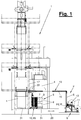
- Figure 1 shows a side view of a baling press (1) which is designed, for example, as a vertical press and which has a filling area and, if necessary, a pre-pressing area as well as a finished or main pressing area. It can be an in Figure 1 Act shown carousel press, which has the filling and pre-pressing area on the left and the finishing pressing area on the right.
- Figure 10 also shows the carousel press (1) in a broken view with the turntable, the lower press rams (31) and a press bale (3) in a perspective view looking from the other side.
- the baler (1) has a high press capacity. You can, for example, according to the WO 2012/101250 A1 be designed and have two parallel feed shafts for filling one or more press boxes (4). In the press box (4), the press bale (3) can be compressed with high pressure between the upper and lower press rams (31). The baling press (1) is assigned a packaging device (2) with which the pressed bale (3) held between the press rams (31) is packaged after the press box (4) has been removed.
- the packaging device provides the pressed bale (3) with a bale packaging (5) which covers several or all sides of the pressed bale (3) and which consists at least partially of a web-shaped packaging material (8).
- the bale packaging (5) is formed at least by a ring-like jacket sheet (7) made of packaging material (8), which is also referred to as a belly bandage, which is placed around the lateral ball surfaces (32). It wraps around and covers the lateral ball surfaces (32) which are exposed and accessible between the press rams.
- a cover film (6) can be attached to the top and / or bottom of the pressed bale (3).
- cover sheets (6) can, for example, according to FIG EP 0 528 893 B1 with the introduction of a foil blank on the press ram (31) before pressing the bale and with the subsequent turning over and placing of the cover foil (6) on the side surfaces of the pressed bale (3).
- cover films (6) can be dispensed with.
- the packaging device (2) has a supply device (9) for the web-shaped packaging material (8) and a wrapping device (10) for attaching the ring-like casing web (7) to the pressed bale (3) held between the press ram (31).
- the web-shaped packaging material (8) is preferably designed as a flexible film web made of a plastic material, e.g. made of polyethylene or polypropylene.
- sheet-like packaging materials made of other materials, e.g. also metallic materials or composite materials, are possible.
- film webs and jacket films (7) are present and described. You can also apply to others accordingly Web-shaped packaging materials (8), material webs, web curtains and jacket webs (7) can be adapted.
- the wrapping device (10) is equipped with an in Figure 1 indicated transport means (20) relative to the pressed bale (3) and to the stationary baling press (1) arranged movably.
- the supply device (9) is spatially and kinematically separated from the wrapping device (10).
- the supply device (9) is arranged in a stationary manner.
- the supply device (9) has a receptacle (12) for a web supply (11) of packaging material (8).
- this web supply (11) is designed as a roll or coil, the receptacle (12) being designed as a rotatable coil receptacle for unwinding the coil.
- the supply device (9) has two coil receptacles (12) for a coil (11) in the operating position and for a replacement coil (11) in the standby position.
- the receptacles (12) are arranged on a frame (14) on which controllable and driven conveying means (16), e.g. drive rollers, for the coil withdrawal and transport of the packaging material (8) are arranged.
- a device for connecting the web ends when changing coils can also be arranged in the area of the receptacles (12).
- the receptacle (s) (12) is / are arranged at a spatial distance from the pressed bale (3) and possibly from the baling press (1) and in a stationary manner.
- a web guide (13) is provided for feeding the packaging material (8) from the receptacle (12) to the wrapping device (10). This bridges the distance to the pressed bale (3) that is held and has a guide arm (15) for the packaging material (8), which is located above the pressed bale (3) and the wrapping device (10).
- Supporting and guiding means (33) for example freely rotatable rollers, and possibly conveying means (16) can be arranged on the guide arm (15).
- the web guide (13), in particular the guide arm (15), is on the one hand part of the frame (14) or is arranged on it and, on the other hand, has a connection at the front free end for attachment to a support part of the baler (1), in particular to a press stand (17), on. At the free end there can also be pulleys (33) for the packaging material (8). From the stationary free end, the film web (8) is fed to an inlet (29) of the movable wrapping device (10).
- the coils (11) are arranged lying down, in particular horizontally, the withdrawn packaging material (8) also assuming a lying position on the guide arm (15), which is preferably oriented horizontally. In this position it is fed to the wrapping device (10).
- the high-lying arrangement of the guide arm (15) and the packaging material (8) in this area allows lateral access to the pressed bale (3) on the baling press (1). This access can be used on the one hand for manual handling or for other manual work on the pressed bale (3).
- a removal device (not shown) or other automatic devices for bale handling can also be arranged here.
- the means of transport (20) can also be moved out of this access area into a rest position and allow access.
- the wrapping device (10) has a variable web store (23) for the supplied packaging material (8).
- the travel movement of the means of transport (20) and the supply line for the packaging material (8) from the supply device (9) can be compared with one another, so that a low-stress, safe transport of the packaging material (8) is possible. This is particularly true when, as in the embodiment shown in FIG Figure 1 the direction of travel of the means of transport (20) when the jacket film (7) is applied and the direction of feed of the packaging material (8) are in opposite directions.
- the web memory (23) takes, for example, the length of the film web required for the associated jacket film area and is emptied when the jacket film (7) is put on. This takes place during the forward movement of the wrapping device (10) and its transport means (20). During this movement, the supply device (9) can replenish the packaging material (8) which is refilled into the web store (23) during the backward movement.
- the web store (23) is designed as a controllable dancer (24) with tensioning rollers (25, 26) for the packaging material (8) that can be adjusted relative to one another.
- Figure 5 illustrates this arrangement in a section and looking from above.
- the dancer (24) several tension loops of the web-shaped packaging material (8) are formed between the stationary tensioning rollers (25) and the movable tensioning rollers (26) arranged on a controllable tensioning carriage.
- the web store (23), in particular the dancer (24), is preceded by a web deflection (22) with which the horizontally fed film web (8) is rotated through 90 ° into an upright position, with which the jacket film (7) is wrapped around the Press bale (3) is placed.
- the tensioning rollers (25, 26) also have an upright position.
- the web deflection (22) can, for example, via an in Figure 3 shown inclined and rounded guardrail.
- the wrapping device (10) can also have controllable and driven conveying means (27) for the web-shaped packaging material (8).
- the packaging material (8) is looped to pulleys on a rear support arm and from there back to an outlet (30) of the wrapping device (10), where the packaging material (8) in the direction of the pressed bale (3) according to Figure 2 and 3 exit.
- the outlet (10) can according to Figure 5 be movable transversely to the pressed bale (3) and have a controlled extendable and eg driven by a cylinder carriage with upright guide rollers.
- the wrapping device (10) can stretch a film curtain (21) which extends across the pressed bale (3) and its rear face and which then moves around the pressed bale (3) in a U-shape when the wrapping device (10) moves. placed and closed at the other front end to form a ring.
- the wrapping device (10) has a separating and welding device (28) which is arranged on the movable outlet (30) or in the vicinity thereof.
- the separating and welding device (28) can be arranged so that it can be advanced towards the pressed bale (3), it being located, for example, on the carriage of the outlet (30).
- the separating and welding device (28) on the one hand closes the jacket film (7) formed by means of the film curtain (21) at the front end and thereby separates the jacket film (7) from the supplied packaging material (8). It connects, in particular welded, the ends of the cladding film (7) to one another. At the same time, the free ends of the supplied packaging material (8) produced during the separation process are also connected to one another, a closed film curtain (21) being formed again.
- the wrapping device (10) can be reinserted into an in Figure 1 Move back the starting position shown.
- the wrapping device (10) can be constructed in different ways. In particular, it can be designed in one piece or in several pieces.
- a multi-part wrapping device (10) has two feed devices (18, 19) which are arranged on both sides of the pressed bale (3) and the baling press (1) and which each have their own transport means (20) designed, for example, as a trolley. exhibit.
- the feed devices (18, 19) each have the aforementioned design of the wrapping device (10) with the web deflection (22), the web store (23) and the conveying means (27), the said film curtain (21) being arranged between the two opposite one another in mirror image and feeding devices (18, 19) that are moved synchronously are clamped.
- Figure 3 shows this arrangement.
- the cutting and welding device (28) can be assigned in whole or in part to one or both feed devices (18, 19).
- the welding device (28) is designed in any suitable manner. It can work with heating bars or heating wires with a higher temperature, which are suitable for PE foils, for example. For temperature-sensitive PP films, in particular so-called ribbon films, the Welding device (28) work with ultrasound.
- the separating and welding device (28) can be in one of the EP 0 294 820 B1 and / or the EP 0 528 892 B1 be constructed and function accordingly.
- the two feed devices (18, 19) are each connected to their own supply device (9) of the type described above, so that the packaging material (8) is fed to both sides of the pressed bale (3) or the baling press (1).
- a single and one-sided arrangement of a supply device (9) in connection with a single wrapping device (10) can be provided, with only one web (8) of packaging material on one side of the bale from the stationary Supply device (9) of the wrapping device (10) is supplied.
- the latter can consist of several parts and, for example, according to the EP 0 528 892 B1 be designed, with a film intake and on the other a transversely extendable film arm are arranged on one side of the bale and are each located on a transport means (20).
- bale packaging (5) or the pressed bale (3) provided with a jacket film (7) can then be supplemented with an expansion hood or another packaging means.
- the baler (1) can have a different structural design. It can, for example, be designed as a horizontal press and have vertically aligned press rams.
- the packaging device (2) is designed and arranged accordingly to adapt to this. In this case, the jacket (7) is placed around horizontal and vertical free side surfaces (32) of the pressed bale (3).
- the baling press (1) can have locally and functionally separate pre-press and finished press areas. It can in particular be designed as a press system with several prepresses and a common finishing press.
- the packaging device (2) is arranged on a possibly stand-alone finishing press (1).
Landscapes
- Engineering & Computer Science (AREA)
- Mechanical Engineering (AREA)
- Basic Packing Technique (AREA)
- Storage Of Harvested Produce (AREA)
- Auxiliary Devices For And Details Of Packaging Control (AREA)
Description
- Die Erfindung betrifft eine Ballenpresse mit einer Verpackungseinrichtung und ein Verpackungsverfahren für hochverdichtete Pressballen mit den Merkmalen der selbstständigen Verfahrens- und Vorrichtungsansprüche.
- Eine Ballenpresse mit einer Verpackungseinrichtung für hoch verdichtete Pressballen ist aus
EP 0 695 690 A1 bekannt. Sie ist als Karussell-Ballenpresse mit im Kreis wandernden Pressstempeln ausgebildet. Die Verpackungseinrichtung weist an beiden Ballenseiten jeweils eine Versorgungseinrichtung mit einem Folienrollenhalter nebst einer einzelnen stehenden Folienrolle in Betriebsstellung sowie eine längs der Ballenseite verfahrbare Mantelumlegungseinheit auf. Die Folienenden beider Folienrollen sind miteinander verbunden, wobei zwischen den Folienrollen eine gestreckte Folienwand aufgespannt und gehalten wird. Die Folienrollen sind jeweils drehbar und ortsfest tangential außerhalb der Kreisbahn der Pressstempel angeordnet. Die beidseitigen Mantelumlegungseinheit nehmen durch ihre Fahrbewegung entlang des stationären Pressballens die Folienwand mit, ziehen die Folie von den Folienrollen ab und bringen einen ringförmigen Folienmantel am Pressballen an. - Die
WO 03/006318 A1 - Eine andere Verpackungseinrichtung für hoch verdichtete Pressballen an einer Ballenpresse ist aus der
EP 0 294 820 B1 bekannt. Die Verpackungseinrichtung weist eine Versorgungseinrichtung für eine Folienbahn und eine Einhüllvorrichtung zum Anbringen eines umgebenden Folienmantels an dem zwischen Pressstempeln gehaltenen Pressballen auf, die eine räumliche und kinematische Einheit bilden und gemeinsam auf einen Transportmittel angeordnet sind. Die Verpackungseinrichtung spannt einen Folienvorhang auf und legt ihn als Bauchbinde seitlich um den Pressballen. - Die
EP 0 528 892 B1 zeigt eine Variante einer solchen Verpackungseinrichtung mit einer anderen konstruktiven Ausbildung der Versorgungseinrichtung und der Einhüllvorrichtung. - Aus der
EP 1 029 786 A2 ist eine Verpackungseinrichtung für palettierte Gutstapel bekannt, bei der die Gutstapel auf einem Förderer durch einen stationären aufgespannten Folienvorhang bewegt werden. Die Gutstapel nehmen durch ihre Transportbewegung den Folienvorhang mit und legen die Folie an. - Es ist Aufgabe der vorliegenden Erfindung, eine bessere Verpackungstechnik aufzuzeigen.
- Die Erfindung löst diese Aufgabe mit den Merkmalen im Verfahrens- und Vorrichtungshauptanspruch.
- Die beanspruchte Verpackungstechnik, insbesondere die Verpackungseinrichtung und das Verpackungsverfahren, haben den Vorteil einer gesteigerten Leistungsfähigkeit und einer verbesserten Sicherheit.
- Durch die räumliche Trennung kann die Versorgungseinrichtung mit Distanz zum Pressballen bzw. zur Ballenpresse und damit außerhalb eines Sicherheitsbereichs an der Ballenpresse angeordnet sein. Dies erlaubt einen Wechsel bzw. Nachschub an Verpackungsmaterial, insbesondere Wickel oder Coils, ohne Störung oder Stillsetzung der Ballenpresse aus Sicherheitsgründen.
- Die Versorgungseinrichtung ist stationär angeordnet, was die Zugänglichkeit, die Handhabung und den Wechsel des Verpackungsmaterials, insbesondere Coils, erleichtert. Dabei wird die Vorratskapazität wesentlich gesteigert. Für Ersatzcoils ist genügend Platz vorhanden. Der Durchmesser und das Gewicht der Coils und Ersatzcoils können wesentlich größer als beim eingangs Stand der Technik sein. Außerdem kann eine Verbindung der Bahnenden beim Coilwechsel wesentlich leichter und schneller vonstatten gehen, insbesondere bei liegenden Coils.
- Die Versorgungseinrichtung weist eine Aufnahme für einen als Coil ausgebildeten Bahnvorrat von Verpackungsmaterials in Betriebsstellung sowie mindestens eine weitere Aufnahme (12) für einen Ersatz-Coil in Bereitschaftsstellung auf. Sie kann auch eine Bahnführung für die Zuleitung des Verpackungsmaterials zur Einhüllvorrichtung aufweisen. Die Bahnführung kann einen hochliegenden und oberhalb des gehaltenen Pressballens angeordneten Führungsarm für das Verpackungsmaterial aufweisen. Die Bahnführung, insbesondere der Führungsarm, kann einen Anschluss zur Befestigung an einem Pressenständer der Ballenpresse aufweisen.
- Weitere Vorteile liegen in der Platz- und Gewichtseinsparung am Transportmittel, welches nur noch die Einhüllvorrichtung zu transportieren hat. Dies kann außerdem zu Verbesserungen bei der Beschleunigung und der Fahrgeschwindigkeit des Transportmittels führen, was sich ebenfalls leistungssteigernd auswirkt. Günstig sind außerdem verbesserte Unterbringungsmöglichkeiten für eine oder mehrere Zusatzeinrichtungen auf dem Transportmittel, z.B. eine Umreifungsvorrichtung.
- Die beanspruchte Verpackungstechnik eignet sich besonders für leistungsstarke Ballenpressen. Hierbei kann eine Ballenpresse auch in einen Vorpressen- und Hauptpressenbereich untergliedert sein. Die beanspruchte Verpackungstechnik kann außerdem für das Anbringen zusätzlicher Verpackungsmittel, z.B. einer Dehnhaube ergänzt werden. Zudem besteht die Möglichkeit, am Pressballen eine obere und/oder untere Deckfolie anzubringen, was während des Pressens geschehen kann.
- In den Unteransprüchen sind weitere vorteilhafte Ausgestaltungen der Erfindung angegeben.
- Die Erfindung ist in den Zeichnungen beispielhaft und schematisch dargestellt. Im einzelnen zeigen:
- Figur 1:
- eine Seitenansicht einer Ballenpresse mit einer Verpackungseinrichtung mit einer Versorgungseinrichtung und einer Einhüllvorrichtung,
- Figur 2:
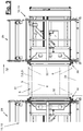
- eine perspektivische Ansicht der Zuführeinrichtung einer Einhüllvorrichtung,
- Figur 3:
- eine Frontansicht einer Einhüllvorrichtung mit zwei beidseits des Pressballens angeordneten Zuführeinrichtungen gemäß Blickrichtung III von
Figur 2 , - Figur 4:
- eine Seitenansicht einer Zuführvorrichtung gemäß Pfeil IV von
Figur 3 , - Figur 5:
- einen Schnitt durch eine Zuführvorrichtung gemäß Schnittlinie V-V von
Figur 4 , - Figur 6:
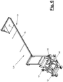
- eine perspektivische Ansicht einer Versorgungseinrichtung,
- Figur 7:
- eine Seitenansicht der Versorgungseinrichtung von
Figur 6 , - Figur 8:
- eine Frontansicht der Versorgungseinrichtung gemäß Pfeil VIII von
Figur 7 , - Figur 9:
- einen Schnitt durch die Versorgungseinrichtung gemäß Schnittlinie IX-IX von
Figur 8 und - Figur 10:
- eine perspektivische Ansicht der Verpackungseinrichtung von
Figur 1 bis 9 und eines Teils der Ballenpresse. - Die Erfindung betrifft eine Ballenpresse (1) mit einer Verpackungseinrichtung (2) und einem Verpackungsverfahren für hochverdichtete Pressballen (3).
- Die Pressballen (3) werden aus Textilfasern, insbesondere Naturfasern oder Kunstfasern, hergestellt und anschließend mit der Verpackungseinrichtung (2) verpackt.
-
Figur 1 zeigt in der Seitenansicht eine Ballenpresse (1), die z.B. als Vertikalpresse ausgebildet ist und die einen Füll- und ggf. Vorpressbereich sowie einen Fertig- oder Hauptpressbereich aufweist. Es kann sich um eine inFigur 1 gezeigte Karussellpresse handeln, die links den Füll- und Vorpressbereich und rechts den Fertigpressbereich hat. -
Figur 10 zeigt ebenfalls die Karussellpresse (1) in einer abgebrochenen Darstellung mit dem Drehtisch, den unteren Pressstempeln (31) und einem Pressballen (3) in einer perspektivischen Ansicht mit Blick von der anderen Seite. - Die Ballenpresse (1) hat eine hohe Pressenkapazität. Sie kann z.B. gemäß der
WO 2012/101250 A1 ausgebildet sein und zwei parallele Zuführschächte für die Befüllung von einem oder mehreren Presskästen (4) aufweisen. In dem Presskasten (4) kann der Pressballen (3) zwischen oberen und unteren Pressstempeln (31) mit hohem Druck verdichtet werden. Der Ballenpresse (1) ist eine Verpackungseinrichtung (2) zugeordnet, mit der der gepresste und zwischen den Pressstempeln (31) gehaltene Pressballen (3) nach Entfernen des Presskastens (4) verpackt wird. - Der Pressballen (3) erhält durch die Verpackungseinrichtung eine Ballenverpackung (5), die mehrere oder auch alle Seiten des Pressballens (3) bedeckt und die zumindest teilweise aus einem bahnförmigen Verpackungsmaterial (8) besteht. Die Ballenverpackung (5) wird zumindest von einer um die seitlichen Ballflächen (32) gelegten ringartigen Mantelbahn (7) aus Verpackungsmaterial (8) gebildet, die auch als Bauchbinde bezeichnet wird. Sie umschlingt und bedeckt die seitlichen Ballflächen (32), die zwischen den Pressstempeln frei liegen und zugänglich sind. Zusätzlich kann eine Deckfolie (6) an der Oberseite und/oder Unterseite des Pressballens (3) angebracht sein.
- Das Anbringen solcher Deckfolien (6) kann z.B. gemäß der
EP 0 528 893 B1 mit Einbringen eines Folienzuschnitts am Pressstempel (31) vor dem Verpressen des Ballens und mit nachfolgendem Umschlagen und Anlegen der Deckfolie (6) an den Seitenflächen des Pressballens (3) erfolgen. Auf eine oder mehrere Deckfolien (6) kann alternativ verzichtet werden. - Die Verpackungseinrichtung (2) weist eine Versorgungseinrichtung (9) für das bahnförmige Verpackungsmaterial (8) und eine Einhüllvorrichtung (10) zum Anbringen der ringartigen Mantelbahn (7) an dem zwischen den Pressstempel (31) gehaltenen Pressballen (3) auf. Das bahnförmige Verpackungsmaterial (8) ist bevorzugt als biegelastische Folienbahn aus einem Kunststoffmaterial, z.B. aus Polyäthylen oder Polypropylen ausgebildet. Alternativ sind bahnartige Verpackungsmaterialien aus anderen Werkstoffen, z.B. auch metallischen Werkstoffen oder Verbundwerkstoffen, möglich.
- In den nachfolgend erläuterten Ausführungsbeispielen sind Folienbahnen und Mantelfolien (7) vorhanden und beschrieben. Sie können entsprechend auch auf andere bahnförmige Verpackungsmaterialien (8), Materialbahnen, Bahnvorhänge und Mantelbahnen(7) adaptiert werden.
- Die Einhüllvorrichtung (10) ist mit einem in
Figur 1 angedeuteten Transportmittel (20) relativ zum Pressballen (3) und zur stationären Ballenpresse (1) beweglich angeordnet. Die Versorgungseinrichtung (9) ist räumlich und kinematisch getrennt von der Einhüllvorrichtung (10) angeordnet. Die Versorgungseinrichtung (9) ist stationär angeordnet. - Die Versorgungseinrichtung (9) weist eine Aufnahme (12) für einen Bahnvorrat (11) von Verpackungsmaterial (8) auf. Dieser Bahnvorrat (11) ist in den gezeigten Ausführungsbeispielen als Wickel oder Coil ausgebildet, wobei die Aufnahme (12) als drehfähige Coilaufnahme zum Abwickeln des Coils ausgebildet ist. Die Versorgungseinrichtung (9) weist zwei Coilaufnahmen (12) für einen in Betriebsstellung befindlichen Coil (11) und für einen Ersatzcoil (11) in Bereitschaftsstellung auf. Die Aufnahmen (12) sind an einem Gestell (14) angeordnet, an dem auch steuerbare und angetriebene Fördermittel (16), z.B. Treibwalzen, für den Coilabzug und Transport des Verpackungsmaterials (8) angeordnet sind. Im Bereich der Aufnahmen (12) kann auch eine Vorrichtung zum Verbinden der Bahnenden beim Coilwechsel angeordnet sein.
- Die Aufnahme(n) (12) ist/sind mit räumlichen Abstand zum Pressballen (3) und ggf. zur Ballenpresse (1) sowie stationär angeordnet. Für die Zuleitung des Verpackungsmaterials (8) von der Aufnahme (12) zur Einhüllvorrichtung (10) ist eine Bahnführung (13) vorgesehen. Diese überbrückt die Distanz zum gehaltenen Pressballen (3) und weist einen hochliegenden und oberhalb des gehaltenen Pressballens (3) sowie der Einhüllvorrichtung (10) angeordneten Führungsarm (15) für das Verpackungsmaterial (8) auf. An dem Führungsarm (15) das Verpackungsmaterial (8) auf. An dem Führungsarm (15) können Stütz- und Führungsmittel (33), z.B. frei drehbare Rollen, sowie ggf. Fördermittel (16) angeordnet sein. Die Bahnführung (13), insbesondere der Führungsarm (15), ist einerseits Bestandteil des Gestells (14) oder ist an diesem angeordnet und weist andererseits am vorderen freien Ende einen Anschluss zur Befestigung an einem Stützteil der Ballenpresse (1), insbesondere an einem Pressenständer (17), auf. An dem freien Ende können außerdem Umlenkrollen (33) für das Verpackungsmaterial (8) vorhanden sein. Von dem stationären freien Ende wird die Folienbahn (8) einem Einlass (29) der beweglichen Einhüllvorrichtung (10) zugeleitet.
- Die Coils (11) sind liegend, insbesondere horizontal, angeordnet, wobei auch das abgezogenen Verpackungsmaterial (8) auf dem bevorzugt horizontal ausgerichteten Führungsarm (15) eine liegende Position einnimmt. In dieser Lage wird es der Einhüllvorrichtung (10) zugeführt. Die hochliegende Anordnung des Führungsarms (15) und des Verpackungsmaterials (8) in diesem Bereich lässt an der Ballenpresse (1) einen seitlichen Zugang zum gehaltenen Pressballen (3) frei. Dieser Zugang kann einerseits für eine manuelle Handhabung oder für andere manuelle Arbeiten am Pressballen (3) genutzt werden. Andererseits kann hier auch eine Entnahmeeinrichtung (nicht dargestellt) oder andere automatische Einrichtungen zum Ballenhandling angeordnet sein. Das Transportmittel (20) kann ebenfalls aus diesem Zugangsbereich in eine Ruhestellung bewegt werden und den Zugang frei geben.
- Die Einhüllvorrichtung (10) weist einen variablen Bahnspeicher (23) für das zugeleitete Verpackungsmaterial (8) auf. Hierdurch können die Fahrbewegung des Transportmittels (20) und die Zuleitung des Verpackungsmaterials (8) von der Versorgungseinrichtung (9) gegeneinander abgeglichen werden, sodass ein belastungsarmer, sicherer Transport des Verpackungsmaterials (8) möglich ist. Dies gilt insbesondere, wenn wie im gezeigten Ausführungsbeispiel von
Figur 1 die Fahrtrichtung des Transportmittels (20) beim Anlegen der Mantelfolie (7) und die Zuleitungsrichtung des Verpackungsmaterials (8) entgegengesetzt gerichtet sind. - Der Bahnspeicher (23) nimmt z.B. die für den zugehörigen Mantelfolienbereich erforderliche Folienbahnlänge auf und wird beim Anlegen der Mantelfolie (7) geleert. Dies geschieht während der Vorwärtsbewegung der Einhüllvorrichtung (10) und ihres Transportmittels (20). Während dieser Bewegung kann von der Versorgungseinrichtung (9) Verpackungsmaterial (8) nachgefördert werden, welches bei der Rückwärtsbewegung in den Bahnspeicher (23) wieder eingefüllt wird.
- Der Bahnspeicher (23) ist in der bevorzugten Ausführungsform als steuerbarer Tänzer (24) mit relativ zueinander verstellbaren Spannrollen (25,26) für das Verpackungsmaterial (8) ausgebildet.
Figur 5 verdeutlicht diese Anordnung in einem Schnitt und mit Blickrichtung von oben. Im Tänzer (24) werden zwischen den stationären Spannrollen (25) und den an einem steuerbaren Spannwagen angeordneten beweglichen Spannrollen (26) mehrere Spannschlaufen des bahnförmigen Verpackungsmaterials (8) gebildet. - Eingangseitig ist dem Bahnspeicher (23), insbesondere dem Tänzer (24), eine Bahnumlenkung (22) vorgeschaltet, mit dem die liegend zugeführte Folienbahn (8) um 90° in eine aufrechte Lage gedreht wird, mit der die Mantelfolie (7) um den Pressballen (3) gelegt wird. Die Spannrollen (25, 26) haben ebenfalls eine aufrechte Lage. Die Bahnumlenkung (22) kann z.B. über eine in
Figur 3 dargestellte schräge und gerundete Leitschiene erfolgen. - Oberhalb der Bahnumlenkung (22) ist der Einlass (29) der Einhüllvorrichtung (10) mit Umlenkrollen angeordnet, die das bahnförmige Verpackungsmaterial (8) von dem vorderen Ende des Führungsarms (15) übernehmen.
Figur 1 und4 zeigen diese Anordnung. - Die Einhüllvorrichtung (10) kann ebenfalls steuerbare und angetriebene Fördermittel (27) für das bahnförmige Verpackungsmaterial (8) aufweisen. An der Ausgangsseite des Bahnspeichers (23), insbesondere Tänzers (24), wird das Verpackungsmaterial (8) in einer Schlaufe zu Umlenkrollen an einem rückseitigen Stützarm und von dort wieder zurück zu einem Auslass (30) der Einhüllvorrichtung (10) geführt, an dem das Verpackungsmaterial (8) in Richtung zum Pressballen (3) gemäß
Figur 2 und3 austritt. Der Auslass (10) kann gemäßFigur 5 quer zum Pressballen (3) beweglich sein und einen gesteuert ausfahrbaren und z.B. von einem Zylinder angetriebenen Wagen mit aufrechten Führungsrollen aufweisen. - Wie
Figur 3 verdeutlicht, kann die Einhüllvorrichtung (10) einen Folienvorhang (21) aufspannen, der quer über den gehaltenen Pressballen (3) und dessen rückwärtige Stirnseite reicht und der anschließend bei einer Fahrbewegung der Einhüllvorrichtung (10) U-förmig um den gehaltenen Pressballen (3) gelegt und am anderen vorderen Stirnende zu einem Ring geschlossen wird. Hierfür weist die Einhüllvorrichtung (10) eine Trenn- und Schweißvorrichtung (28) auf, welche am beweglichen Auslass (30) oder in dessen Nähe angeordnet ist. Die Trenn- und Schweißvorrichtung (28) kann zum Pressballen (3) zustellbar angeordnet sein, wobei sie sich z.B. an dem Wagen des Auslass (30) befindet. - Die Trenn- und Schweißvorrichtung (28) schließt einerseits die mittels des Folienvorhangs (21) gebildete Mantelfolie (7) am Stirnende und trennt dabei die Mantelfolie (7) vom zugeführten Verpackungsmaterial (8) ab. Sie verbindet, insbesondere verschweißt, dabei die Enden der Mantelfolie (7) miteinander. Gleichzeitig werden dabei auch die beim Trennvorgang entstehenden freien Enden des zugeführten Verpackungsmaterials (8) miteinander verbunden, wobei wieder ein geschlossener Folienvorhang (21) gebildet wird. Nach Entfernen des mit der Mantelfolie (7) versehenen Pressballens (3) aus der Ballenpresse (1) kann die Einhüllvorrichtung (10) wieder in eine in
Figur 1 gezeigte Ausgangsstellung zurückfahren. - Die Einhüllvorrichtung (10) kann in unterschiedlicher Weise konstruktiv ausgeführt sein. Sie kann insbesondere einteilig oder mehrteilig ausgebildet sein.
- Bei der gezeigten Ausführungsform weist eine mehrteilige Einhüllvorrichtung (10) zwei Zuführeinrichtungen (18,19) auf, die beidseits des Pressballens (3) und der Ballenpresse (1) angeordnet sind und die dabei jeweils ein eigenes und z.B. als Trolley ausgebildetes Transportmittel (20) aufweisen. Die Zuführeinrichtungen (18,19) haben dabei jeweils die vorgenannte Ausbildung der Einhüllvorrichtung (10) mit der Bahnumlenkung (22), dem Bahnspeicher (23) und den Fördermitteln (27), wobei der besagte Folienvorhang (21) zwischen den einander spiegelbildlich gegenüberliegend angeordneten und synchron verfahrenen Zuführeinrichtungen (18, 19) aufgespannt wird.
Figur 3 zeigt diese Anordnung. Die Trenn- und Schweißvorrichtung (28) kann insgesamt oder in Teilen einer oder beiden Zuführeinrichtungen (18, 19) zugeordnet sein. - Die Schweißvorrichtung (28) ist in beliebig geeigneter Weise ausgebildet. Sie kann mit Heizbalken oder Heizdrähten mit höheren Temperatur arbeiten, die z.B. für PE-Folien geeignet sind. Für temperaturempfindliche PP-Folien, insbesondere sog. Bändchenfolien, kann die Schweißvorrichtung (28) mit Ultraschall arbeiten. Die Trenn- und Schweißvorrichtung (28) kann in einer der
EP 0 294 820 B1 und/oder derEP 0 528 892 B1 entsprechenden Weise konstruktiv ausgebildet sein und funktionieren. - Die beiden Zuführeinrichtungen (18,19) sind auch jeweils mit einer eigenen Versorgungseinrichtung (9) der vorbeschriebenen Art verbunden, sodass das Verpackungsmaterial (8) an beiden Seiten des Pressballens (3) bzw. der Ballenpresse (1) zugeführt wird.
- In einer anderen, nicht dargestellten Variante der Verpackungseinrichtung (2) kann eine einzelne und einseitige Anordnung einer Versorgungseinrichtung (9) in Verbindung mit einer einzelnen Einhüllvorrichtung (10) vorgesehen sein, wobei nur eine Bahn (8) an Verpackungsmaterial an einer Ballenseite von der stationären Versorgungseinrichtung (9) der Einhüllvorrichtung (10) zugeführt wird. Letztere kann mehrteilig und z.B. entsprechend der
EP 0 528 892 B1 ausgebildet sein, wobei an einer Ballenseite ein Folieneinzug und an der anderen ein quer ausfahrbarer Folienarm angeordnet sind und sich jeweils auf einem Transportmittel (20) befinden. - Abwandlungen der gezeigten und beschriebenen Ausführungsformen sind in verschiedener Weise möglich. Dies betrifft die konstruktive Ausbildung und Anordnung der Einhüllvorrichtung (10) sowie der Ballenpresse (1). Insbesondere können auch die Merkmale der vorbeschriebenen Ausführungsbeispiele und ihrer Abwandlungen im Rahmen der Ansprüche untereinander kombiniert und auch vertauscht werden.
- Die Ballenverpackung (5) bzw. der mit einer Mantelfolie (7) versehene Pressballen (3) kann anschließend mit einer Dehnhaube oder einem anderen Packmittel ergänzt werden.
- Die Ballenpresse (1) kann eine andere konstruktive Ausbildung haben. Sie kann z.B. als Horizontalpresse ausgebildet sein und vertikal ausgerichtete Pressstempel aufweisen. Die Verpackungseinrichtung (2) ist in Anpassung hieran entsprechend ausgebildet und angeordnet. In diesem Fall wird der Mantel (7) um horizontale und vertikale freie Seitenflächen (32) des Pressballens (3) gelegt. Ferner kann die Ballenpresse (1) örtlich und funktional getrennte Vor- und Fertigpressbereiche aufweisen. Sie kann insbesondere als Pressenanlage mit mehreren Vorpressen und einer gemeinsamen Fertigpresse ausgebildet sein. Die Verpackungseinrichtung (2) ist dabei an einer ggf. allein stehenden Fertigpresse (1) angeordnet.
-
- 1
- Ballenpresse
- 2
- Verpackungseinrichtung
- 3
- Pressballen
- 4
- Presskasten
- 5
- Ballenverpackung
- 6
- Deckfolie
- 7
- Mantelbahn, Mantelfolie, Mantel
- 8
- Verpackungsmaterial, Folienbahn
- 9
- Versorgungseinrichtung
- 10
- Einhüllvorrichtung
- 11
- Bahnvorrat, Folienvorrat, Coil
- 12
- Aufnahme, Coilaufnahme stationär
- 13
- Bahnführung
- 14
- Gestell
- 15
- Führungsarm
- 16
- Fördermittel
- 17
- Pressenständer
- 18
- Zuführeinrichtung
- 19
- Zuführeinrichtung
- 20
- Transportmittel, Trolley
- 21
- Folienvorhang, Bahnvorhang
- 22
- Bahnumlenkung
- 23
- Bahnspeicher
- 24
- Tänzer
- 25
- Spannrolle stationär
- 26
- Spannrolle beweglich
- 27
- Fördermittel
- 28
- Trenn- und Schweißvorrichtung
- 29
- Einlass
- 30
- Auslass
- 31
- Pressstempel
- 32
- Seitenfläche
- 33
- Führungsmittel, Umlenkrolle
Claims (14)
- Ballenpresse für hochverdichtete Pressballen (3) mit einer Verpackungseinrichtung (2), die eine Versorgungseinrichtung (9) für ein bahnförmiges Verpackungsmaterial (8), insbesondere eine Folienbahn, und eine Einhüllvorrichtung (10) zum Anbringen einer ringförmigen umgebenden Mantelbahn (7), insbesondere eines Folienmantels, an den freien Seitenflächen (32) des zwischen Pressstempeln (31) gehaltenen Pressballens (3) aufweist, wobei die Einhüllvorrichtung (10) mit einem Transportmittel (20) relativ zum Pressballen (3) beweglich angeordnet ist und die Versorgungseinrichtung (9) räumlich und kinematisch getrennt von der Einhüllvorrichtung (10) angeordnet ist, wobei die Versorgungseinrichtung (9) stationär angeordnet ist und eine Aufnahme (12) für einen als Coil ausgebildeten Bahnvorrat (11) von Verpackungsmaterial (8) in Betriebsstellung aufweist, dadurch gekennzeichnet, dass die Versorgungseinrichtung (9) mindestens eine weitere Aufnahme (12) für einen Ersatz-Coil in Bereitschaftsstellung aufweist, wobei die Aufnahmen (12) an einem Gestell (14) angeordnet sind, an dem auch steuerbare und angetriebene Fördermittel (16), insbesondere Treibwalzen, für den Coilabzug und Transport des Verpackungsmaterials (8) angeordnet sind.
- Ballenpresse nach Anspruch 1, dadurch gekennzeichnet, dass die Aufnahme (12) als drehfähige Coilaufnahme zum Abwickeln des Coils ausgebildet ist.
- Ballenpresse nach Anspruch 1 oder 2, dadurch gekennzeichnet, dass die Coils ohne Störung oder Stillsetzung der Ballenpresse wechselbar sind.
- Ballenpresse nach einem der vorhergehenden Ansprüche, dadurch gekennzeichnet, dass im Bereich der Aufnahmen (12) auch eine Vorrichtung zum Verbinden der Bahnenden beim Coilwechsel angeordnet ist.
- Ballenpresse nach einem der vorhergehenden Ansprüche, dadurch gekennzeichnet, dass die Coils (11) liegend, insbesondere horizontal, angeordnet sind.
- Ballenpresse nach einem der vorhergehenden Ansprüche, dadurch gekennzeichnet, dass die Einhüllvorrichtung (10) eine Bahnumlenkung (22) und insbesondere eine Trenn- und Schweißvorrichtung (28) für das Verpackungsmaterial (8) aufweist.
- Ballenpresse nach einem der vorhergehenden Ansprüche, dadurch gekennzeichnet, dass die Versorgungseinrichtung (9) mit Distanz zum Pressballen (3) bzw. zur Ballenpresse (1) und außerhalb eines Sicherheitsbereichs an der Ballenpresse (1) angeordnet ist.
- Ballenpresse nach einem der vorhergehenden Ansprüche, dadurch gekennzeichnet, dass die Einhüllvorrichtung (10) einen variablen Bahnspeicher (23) für das Verpackungsmaterial (8) aufweist, wobei insbesondere der Bahnspeicher (23) als steuerbarer Tänzer (24) mit relativ zueinander verstellbaren Spannrollen (25,26) für das Verpackungsmaterial (8) ausgebildet ist.
- Ballenpresse nach einem der vorhergehenden Ansprüche, dadurch gekennzeichnet, dass die Verpackungseinrichtung (2) zwei Versorgungseinrichtungen (9) und die Einhüllvorrichtung (10) zwei beidseits des Pressballens (3) auf jeweils einem Transportmittel (20) angeordnete und mit jeweils einer Versorgungseinrichtung (9) verbundene Zuführeinrichtungen (18,19) aufweist, die dazu vorgesehen und ausgebildet sind, zwischen sich einen aufrechten Bahnvorhang (21), insbesondere Folienvorhang, aufzuspannen und diesen seitlich um den Pressballen (3) zu legen.
- Ballenpresse nach einem der Ansprüche 1 bis 8, dadurch gekennzeichnet, dass die Verpackungseinrichtung (2) eine einzelne und einseitige Anordnung einer Versorgungseinrichtung (9) in Verbindung mit einer einzelnen Einhüllvorrichtung (10) aufweist, wobei nur eine Bahn (8) an Verpackungsmaterial (8) an einer Ballenseite von der stationären Versorgungseinrichtung (9) der Einhüllvorrichtung (10) zugeführt wird.
- Verfahren zum Verpacken von hochverdichteten Pressballen (3) an einer Ballenpresse (1) mittels einer Verpackungseinrichtung (2), wobei eine Einhüllvorrichtung (10) mit einem Transportmittel (19) relativ zum Pressballen (3) bewegt wird und einen ringförmigen Mantel (7) aus einem bahnförmigen Verpackungsmaterial (8), insbesondere einer Folienbahn, an den freien Seitenflächen (32) des zwischen Pressstempeln (31) gehaltenen Pressballen (3) anbringt, wobei das bahnförmige Verpackungsmaterial (8) der Einhüllvorrichtung (10) von einer Versorgungseinrichtung (9) zugeführt wird, die räumlich und kinematisch getrennt von der Einhüllvorrichtung (10) angeordnet ist, wobei die Versorgungseinrichtung (9) stationär angeordnet ist und eine Aufnahme (12) für einen als Coil ausgebildeten Bahnvorrat (11) von Verpackungsmaterial (8) in Betriebsstellung aufweist, dadurch gekennzeichnet, dass die Versorgungseinrichtung (9) mindestens eine weitere Aufnahme (12) für einen Ersatz-Coil in Bereitschaftsstellung aufweist, wobei die Aufnahmen (12) an einem Gestell (14) angeordnet sind, an dem auch steuerbare und angetriebene Fördermittel (16), insbesondere Treibwalzen, für den Coilabzug und Transport des Verpackungsmaterials (8) angeordnet sind.
- Verfahren nach Anspruch 11, dadurch gekennzeichnet, dass die Coils ohne Störung oder Stillsetzung der Ballenpresse gewechselt werden.
- Verfahren nach Anspruch 11 oder 12, dadurch gekennzeichnet, dass die Bahnenden beim Coilwechsel verbunden werden, insbesondere bei liegenden Coils.
- Verfahren nach Anspruch 11, 12 oder 13, dadurch gekennzeichnet, dass der mit einer Mantelfolie (7) versehene Pressballen (3) anschließend mit einer Dehnhaube oder einem anderen Packmittel ergänzt wird.
Applications Claiming Priority (3)
| Application Number | Priority Date | Filing Date | Title |
|---|---|---|---|
| DE202013101316.1U DE202013101316U1 (de) | 2013-03-26 | 2013-03-26 | Verpackungseinrichtung |
| EP14718008.7A EP2978672B1 (de) | 2013-03-26 | 2014-03-26 | Verpackungseinrichtung und verpackungsverfahren |
| PCT/EP2014/056032 WO2014154736A1 (de) | 2013-03-26 | 2014-03-26 | Verpackungseinrichtung und verpackungsverfahren |
Related Parent Applications (1)
| Application Number | Title | Priority Date | Filing Date |
|---|---|---|---|
| EP14718008.7A Division EP2978672B1 (de) | 2013-03-26 | 2014-03-26 | Verpackungseinrichtung und verpackungsverfahren |
Publications (2)
| Publication Number | Publication Date |
|---|---|
| EP3326924A1 EP3326924A1 (de) | 2018-05-30 |
| EP3326924B1 true EP3326924B1 (de) | 2021-12-22 |
Family
ID=51264209
Family Applications (2)
| Application Number | Title | Priority Date | Filing Date |
|---|---|---|---|
| EP17206358.8A Active EP3326924B1 (de) | 2013-03-26 | 2014-03-26 | Verpackungseinrichtung und verpackungsverfahren |
| EP14718008.7A Active EP2978672B1 (de) | 2013-03-26 | 2014-03-26 | Verpackungseinrichtung und verpackungsverfahren |
Family Applications After (1)
| Application Number | Title | Priority Date | Filing Date |
|---|---|---|---|
| EP14718008.7A Active EP2978672B1 (de) | 2013-03-26 | 2014-03-26 | Verpackungseinrichtung und verpackungsverfahren |
Country Status (5)
| Country | Link |
|---|---|
| US (1) | US20180057197A1 (de) |
| EP (2) | EP3326924B1 (de) |
| CN (2) | CN105050900B (de) |
| DE (1) | DE202013101316U1 (de) |
| WO (1) | WO2014154736A1 (de) |
Families Citing this family (6)
| Publication number | Priority date | Publication date | Assignee | Title |
|---|---|---|---|---|
| EP3305911A1 (de) | 2016-10-07 | 2018-04-11 | Fraunhofer Gesellschaft zur Förderung der Angewand | Chemisches heizsystem für diagnosegeräte |
| DE102017116164A1 (de) | 2017-07-18 | 2019-01-24 | Autefa Solutions Germany Gmbh | Verpackungseinrichtung und Verpackungsverfahren |
| DE202017104766U1 (de) * | 2017-08-09 | 2018-11-12 | Autefa Solutions Germany Gmbh | Verpackungseinrichtung |
| CN111268215A (zh) * | 2020-03-06 | 2020-06-12 | 杨兴 | 一种用于冷鲜覆膜包装的自动化包装装置 |
| CN113443239A (zh) * | 2020-03-26 | 2021-09-28 | 阮经艳 | 一种物料堆密设备及物料堆密方法 |
| EP4647381A1 (de) * | 2024-05-09 | 2025-11-12 | A.C.M.I. - Societa' Per Azioni | Schrumpffolienverpackungsmaschine |
Citations (1)
| Publication number | Priority date | Publication date | Assignee | Title |
|---|---|---|---|---|
| EP1029786A2 (de) * | 1999-02-19 | 2000-08-23 | Msk-Verpackungs-Systeme Gesellschaft Mit Beschränkter Haftung | Vorrichtung zum Beanderolieren einer Packguteinheit mit einer Schrumpffolienbaderole |
Family Cites Families (18)
| Publication number | Priority date | Publication date | Assignee | Title |
|---|---|---|---|---|
| US2741885A (en) * | 1952-12-08 | 1956-04-17 | Gen Mills Inc | Banding with thermoplastic |
| US4413463A (en) * | 1980-10-23 | 1983-11-08 | Lantech, Inc. | Roller stretch pass through stretching apparatus and process |
| WO1988009748A1 (fr) | 1987-06-10 | 1988-12-15 | Autefa Maschinenfabrik Gmbh | Procede et dispositif d'emballage de balles comprimees |
| DE4015643A1 (de) | 1990-05-15 | 1991-11-21 | Autefa Maschinenfab | Verfahren und vorrichtung zum verpacken von pressballen |
| DE4015642A1 (de) * | 1990-05-15 | 1991-11-21 | Autefa Maschinenfab | Verfahren und vorrichtung zum umschlagen einer deckfolie um einen pressballen |
| IT1241724B (it) * | 1990-06-06 | 1994-02-01 | Ricciarelli Garibaldo S R L | Metodo ed apparecchiatura per la giunzione di estremi di nastri di pellicola saldabile per la formazione di sacchetti ed altro |
| EP0695690B1 (de) * | 1994-07-13 | 1997-06-04 | FLEISSNER GmbH & Co. KG Maschinenfabrik | Verfahren und Vorrichtung zum Verpressen und Verpacken von faserigem Gut in Ballen |
| KR100194537B1 (ko) * | 1994-11-14 | 1999-06-15 | 주봉유 | 개량된 패딩머시인 |
| DE19719239A1 (de) * | 1997-05-07 | 1998-11-12 | Giesecke & Devrient Gmbh | Vorrichtung zur automatischen Bündelung von Blattgut |
| IT1305065B1 (it) * | 1998-12-29 | 2001-04-10 | Tiziano Bielli | Pressa a doppia stazione per materiale tessile |
| ES2190649T3 (es) * | 1999-04-23 | 2003-08-01 | Rpp International Ltd | Procedimiento para envolver un fardo redondo prensado en una prensa empacadora, dispositivo de envoltura en una lamina y prensa empacadora con un dispositivo de envoltura de esta clase con una lamina. |
| ITFI20010135A1 (it) * | 2001-07-13 | 2003-01-13 | Gualchierani Textile Automatio | Pressa per la formazione di balle di materiale tessile od altro,con dispositivo di rivestimento mediante un telo |
| WO2005012098A1 (en) * | 2003-08-04 | 2005-02-10 | Gualchierani Textile Automation S.P.A. | Wrapping device in a press for forming bales of textile material |
| US20060096244A1 (en) * | 2004-11-09 | 2006-05-11 | Aetna Group S.P.A. | Machine for banding groups of palletized products |
| US7594375B2 (en) | 2006-03-22 | 2009-09-29 | Jacques Dussault | Apparatus for bagging material |
| CN201647145U (zh) * | 2010-04-15 | 2010-11-24 | 吴冬仙 | 打包机 |
| EP2668027A1 (de) | 2011-01-28 | 2013-12-04 | AUTEFA Solutions Germany GmbH | Ballenpresse und verfahren zur herstellung verdichteter pressbalen aus faser material |
| BE1021283B1 (nl) * | 2014-01-28 | 2015-10-20 | Valvan Baling Systems Nv | Verpakkingsinrichting en werkwijze voor het verpakken van balen via dergelijke inrichting |
-
2013
- 2013-03-26 DE DE202013101316.1U patent/DE202013101316U1/de not_active Expired - Lifetime
-
2014
- 2014-03-26 CN CN201480018090.5A patent/CN105050900B/zh active Active
- 2014-03-26 CN CN201711060426.6A patent/CN107839925B/zh active Active
- 2014-03-26 EP EP17206358.8A patent/EP3326924B1/de active Active
- 2014-03-26 US US15/559,295 patent/US20180057197A1/en not_active Abandoned
- 2014-03-26 WO PCT/EP2014/056032 patent/WO2014154736A1/de not_active Ceased
- 2014-03-26 EP EP14718008.7A patent/EP2978672B1/de active Active
Patent Citations (1)
| Publication number | Priority date | Publication date | Assignee | Title |
|---|---|---|---|---|
| EP1029786A2 (de) * | 1999-02-19 | 2000-08-23 | Msk-Verpackungs-Systeme Gesellschaft Mit Beschränkter Haftung | Vorrichtung zum Beanderolieren einer Packguteinheit mit einer Schrumpffolienbaderole |
Also Published As
| Publication number | Publication date |
|---|---|
| EP2978672B1 (de) | 2018-01-17 |
| CN107839925A (zh) | 2018-03-27 |
| EP3326924A1 (de) | 2018-05-30 |
| US20180057197A1 (en) | 2018-03-01 |
| EP2978672A1 (de) | 2016-02-03 |
| CN105050900A (zh) | 2015-11-11 |
| WO2014154736A1 (de) | 2014-10-02 |
| CN105050900B (zh) | 2017-12-01 |
| CN107839925B (zh) | 2020-03-27 |
| DE202013101316U1 (de) | 2014-07-11 |
Similar Documents
| Publication | Publication Date | Title |
|---|---|---|
| DE69526150T2 (de) | Verfahren zum gruppenweisen verpacken von gengenständen | |
| DE2923947C2 (de) | ||
| DE60114412T2 (de) | Verfahren und Vorrichtung zum Umwickeln von gruppierten Gegenständen mit einer Stretchfolie | |
| EP2978672B1 (de) | Verpackungseinrichtung und verpackungsverfahren | |
| DE2321457A1 (de) | Verfahren und maschine zum herstellen von laenglichen huellen aus kunststoffolie, z.b. fuer tapetenrollen | |
| DE1561966A1 (de) | Verfahren und Vorrichtung zum Verpacken von Waren | |
| EP2258618A2 (de) | Vorrichtung und Verfahren zum Herstellen einer Verpackungseinheit | |
| CH466989A (de) | Verfahren zum Binden von Gegenständen sowie Bindemaschine zur Ausfürung des Verfahrens | |
| DE4138138C2 (de) | Vorrichtung zum Herstellen von Großpackungen | |
| DE1753819C2 (de) | Vorrichtung zum Herstellen und Stapeln von Formkörpern aus thermoplastischem Schaumstoff | |
| DE19757577A1 (de) | Verfahren und Vorrichtung zum Formen einer Bahn | |
| EP3665086B1 (de) | Verpackungseinrichtung und verpackungsverfahren | |
| EP3967637B1 (de) | Vorrichtung und verfahren zum spleissen und kontinuierlichen bereitstellen einer folienbahn | |
| EP0446322B1 (de) | Anlage zum herstellen von umreiften drahtgitterrollen | |
| DE2917387C3 (de) | Tiefziehmaschine zum Herstellen von Behältern aus thermoplastischer Folie | |
| DE3819854A1 (de) | Verfahren und vorrichtung zum verpacken von gepressten ballen | |
| DE4325159C2 (de) | Vorrichtung zum Aufwickeln und Flachdrücken der Umfangshülle einer Materialbahn-Rolle | |
| DE102014116653B4 (de) | Wickelstation zum Wickeln von Warenbahnen | |
| DE2545813C2 (de) | Vorrichtung zum Verpacken flacher Werkstücke | |
| DE1919889C3 (de) | Einrichtung zum Pressen und Vulkanisieren von Fördergurten und ahnlichen bandförmigen Gummierzeugnissen | |
| DE69313332T2 (de) | Form-, Füll- und Siegelvorrichtung | |
| DE2941068C2 (de) | Faserballenpresse | |
| DE2741804A1 (de) | Tiefziehmaschine zur gleichzeitigen herstellung von mindestens einer behaelterreihe aus thermoplastischer folie mit vorrichtung zum einlegen eines banderolenfoermigen streifens in die einzelnen formen einer formvorrichtung | |
| DE3440416C2 (de) | ||
| DE20320955U1 (de) | Vorrichtung zum Verpacken von Waren zu einem Gebinde |
Legal Events
| Date | Code | Title | Description |
|---|---|---|---|
| PUAI | Public reference made under article 153(3) epc to a published international application that has entered the european phase |
Free format text: ORIGINAL CODE: 0009012 |
|
| STAA | Information on the status of an ep patent application or granted ep patent |
Free format text: STATUS: THE APPLICATION HAS BEEN PUBLISHED |
|
| AC | Divisional application: reference to earlier application |
Ref document number: 2978672 Country of ref document: EP Kind code of ref document: P |
|
| AK | Designated contracting states |
Kind code of ref document: A1 Designated state(s): AL AT BE BG CH CY CZ DE DK EE ES FI FR GB GR HR HU IE IS IT LI LT LU LV MC MK MT NL NO PL PT RO RS SE SI SK SM TR |
|
| STAA | Information on the status of an ep patent application or granted ep patent |
Free format text: STATUS: REQUEST FOR EXAMINATION WAS MADE |
|
| 17P | Request for examination filed |
Effective date: 20181128 |
|
| RBV | Designated contracting states (corrected) |
Designated state(s): AL AT BE BG CH CY CZ DE DK EE ES FI FR GB GR HR HU IE IS IT LI LT LU LV MC MK MT NL NO PL PT RO RS SE SI SK SM TR |
|
| STAA | Information on the status of an ep patent application or granted ep patent |
Free format text: STATUS: EXAMINATION IS IN PROGRESS |
|
| 17Q | First examination report despatched |
Effective date: 20190424 |
|
| GRAP | Despatch of communication of intention to grant a patent |
Free format text: ORIGINAL CODE: EPIDOSNIGR1 |
|
| STAA | Information on the status of an ep patent application or granted ep patent |
Free format text: STATUS: GRANT OF PATENT IS INTENDED |
|
| INTG | Intention to grant announced |
Effective date: 20210712 |
|
| GRAS | Grant fee paid |
Free format text: ORIGINAL CODE: EPIDOSNIGR3 |
|
| GRAA | (expected) grant |
Free format text: ORIGINAL CODE: 0009210 |
|
| STAA | Information on the status of an ep patent application or granted ep patent |
Free format text: STATUS: THE PATENT HAS BEEN GRANTED |
|
| AC | Divisional application: reference to earlier application |
Ref document number: 2978672 Country of ref document: EP Kind code of ref document: P |
|
| AK | Designated contracting states |
Kind code of ref document: B1 Designated state(s): AL AT BE BG CH CY CZ DE DK EE ES FI FR GB GR HR HU IE IS IT LI LT LU LV MC MK MT NL NO PL PT RO RS SE SI SK SM TR |
|
| REG | Reference to a national code |
Ref country code: GB Ref legal event code: FG4D Free format text: NOT ENGLISH |
|
| REG | Reference to a national code |
Ref country code: CH Ref legal event code: EP |
|
| REG | Reference to a national code |
Ref country code: DE Ref legal event code: R096 Ref document number: 502014016050 Country of ref document: DE |
|
| REG | Reference to a national code |
Ref country code: AT Ref legal event code: REF Ref document number: 1456913 Country of ref document: AT Kind code of ref document: T Effective date: 20220115 |
|
| REG | Reference to a national code |
Ref country code: IE Ref legal event code: FG4D Free format text: LANGUAGE OF EP DOCUMENT: GERMAN |
|
| REG | Reference to a national code |
Ref country code: NL Ref legal event code: FP |
|
| REG | Reference to a national code |
Ref country code: LT Ref legal event code: MG9D |
|
| PG25 | Lapsed in a contracting state [announced via postgrant information from national office to epo] |
Ref country code: RS Free format text: LAPSE BECAUSE OF FAILURE TO SUBMIT A TRANSLATION OF THE DESCRIPTION OR TO PAY THE FEE WITHIN THE PRESCRIBED TIME-LIMIT Effective date: 20211222 Ref country code: LT Free format text: LAPSE BECAUSE OF FAILURE TO SUBMIT A TRANSLATION OF THE DESCRIPTION OR TO PAY THE FEE WITHIN THE PRESCRIBED TIME-LIMIT Effective date: 20211222 Ref country code: FI Free format text: LAPSE BECAUSE OF FAILURE TO SUBMIT A TRANSLATION OF THE DESCRIPTION OR TO PAY THE FEE WITHIN THE PRESCRIBED TIME-LIMIT Effective date: 20211222 Ref country code: BG Free format text: LAPSE BECAUSE OF FAILURE TO SUBMIT A TRANSLATION OF THE DESCRIPTION OR TO PAY THE FEE WITHIN THE PRESCRIBED TIME-LIMIT Effective date: 20220322 |
|
| PG25 | Lapsed in a contracting state [announced via postgrant information from national office to epo] |
Ref country code: SE Free format text: LAPSE BECAUSE OF FAILURE TO SUBMIT A TRANSLATION OF THE DESCRIPTION OR TO PAY THE FEE WITHIN THE PRESCRIBED TIME-LIMIT Effective date: 20211222 Ref country code: NO Free format text: LAPSE BECAUSE OF FAILURE TO SUBMIT A TRANSLATION OF THE DESCRIPTION OR TO PAY THE FEE WITHIN THE PRESCRIBED TIME-LIMIT Effective date: 20220322 Ref country code: LV Free format text: LAPSE BECAUSE OF FAILURE TO SUBMIT A TRANSLATION OF THE DESCRIPTION OR TO PAY THE FEE WITHIN THE PRESCRIBED TIME-LIMIT Effective date: 20211222 Ref country code: HR Free format text: LAPSE BECAUSE OF FAILURE TO SUBMIT A TRANSLATION OF THE DESCRIPTION OR TO PAY THE FEE WITHIN THE PRESCRIBED TIME-LIMIT Effective date: 20211222 Ref country code: GR Free format text: LAPSE BECAUSE OF FAILURE TO SUBMIT A TRANSLATION OF THE DESCRIPTION OR TO PAY THE FEE WITHIN THE PRESCRIBED TIME-LIMIT Effective date: 20220323 |
|
| PGFP | Annual fee paid to national office [announced via postgrant information from national office to epo] |
Ref country code: TR Payment date: 20220324 Year of fee payment: 9 Ref country code: NL Payment date: 20220324 Year of fee payment: 9 |
|
| PG25 | Lapsed in a contracting state [announced via postgrant information from national office to epo] |
Ref country code: SM Free format text: LAPSE BECAUSE OF FAILURE TO SUBMIT A TRANSLATION OF THE DESCRIPTION OR TO PAY THE FEE WITHIN THE PRESCRIBED TIME-LIMIT Effective date: 20211222 Ref country code: SK Free format text: LAPSE BECAUSE OF FAILURE TO SUBMIT A TRANSLATION OF THE DESCRIPTION OR TO PAY THE FEE WITHIN THE PRESCRIBED TIME-LIMIT Effective date: 20211222 Ref country code: RO Free format text: LAPSE BECAUSE OF FAILURE TO SUBMIT A TRANSLATION OF THE DESCRIPTION OR TO PAY THE FEE WITHIN THE PRESCRIBED TIME-LIMIT Effective date: 20211222 Ref country code: PT Free format text: LAPSE BECAUSE OF FAILURE TO SUBMIT A TRANSLATION OF THE DESCRIPTION OR TO PAY THE FEE WITHIN THE PRESCRIBED TIME-LIMIT Effective date: 20220422 Ref country code: ES Free format text: LAPSE BECAUSE OF FAILURE TO SUBMIT A TRANSLATION OF THE DESCRIPTION OR TO PAY THE FEE WITHIN THE PRESCRIBED TIME-LIMIT Effective date: 20211222 Ref country code: EE Free format text: LAPSE BECAUSE OF FAILURE TO SUBMIT A TRANSLATION OF THE DESCRIPTION OR TO PAY THE FEE WITHIN THE PRESCRIBED TIME-LIMIT Effective date: 20211222 Ref country code: CZ Free format text: LAPSE BECAUSE OF FAILURE TO SUBMIT A TRANSLATION OF THE DESCRIPTION OR TO PAY THE FEE WITHIN THE PRESCRIBED TIME-LIMIT Effective date: 20211222 |
|
| PG25 | Lapsed in a contracting state [announced via postgrant information from national office to epo] |
Ref country code: PL Free format text: LAPSE BECAUSE OF FAILURE TO SUBMIT A TRANSLATION OF THE DESCRIPTION OR TO PAY THE FEE WITHIN THE PRESCRIBED TIME-LIMIT Effective date: 20211222 |
|
| REG | Reference to a national code |
Ref country code: DE Ref legal event code: R097 Ref document number: 502014016050 Country of ref document: DE |
|
| PG25 | Lapsed in a contracting state [announced via postgrant information from national office to epo] |
Ref country code: IS Free format text: LAPSE BECAUSE OF FAILURE TO SUBMIT A TRANSLATION OF THE DESCRIPTION OR TO PAY THE FEE WITHIN THE PRESCRIBED TIME-LIMIT Effective date: 20220422 |
|
| PLBE | No opposition filed within time limit |
Free format text: ORIGINAL CODE: 0009261 |
|
| STAA | Information on the status of an ep patent application or granted ep patent |
Free format text: STATUS: NO OPPOSITION FILED WITHIN TIME LIMIT |
|
| PG25 | Lapsed in a contracting state [announced via postgrant information from national office to epo] |
Ref country code: MC Free format text: LAPSE BECAUSE OF FAILURE TO SUBMIT A TRANSLATION OF THE DESCRIPTION OR TO PAY THE FEE WITHIN THE PRESCRIBED TIME-LIMIT Effective date: 20211222 Ref country code: DK Free format text: LAPSE BECAUSE OF FAILURE TO SUBMIT A TRANSLATION OF THE DESCRIPTION OR TO PAY THE FEE WITHIN THE PRESCRIBED TIME-LIMIT Effective date: 20211222 Ref country code: AL Free format text: LAPSE BECAUSE OF FAILURE TO SUBMIT A TRANSLATION OF THE DESCRIPTION OR TO PAY THE FEE WITHIN THE PRESCRIBED TIME-LIMIT Effective date: 20211222 |
|
| REG | Reference to a national code |
Ref country code: CH Ref legal event code: PL |
|
| GBPC | Gb: european patent ceased through non-payment of renewal fee |
Effective date: 20220326 |
|
| 26N | No opposition filed |
Effective date: 20220923 |
|
| PG25 | Lapsed in a contracting state [announced via postgrant information from national office to epo] |
Ref country code: LU Free format text: LAPSE BECAUSE OF NON-PAYMENT OF DUE FEES Effective date: 20220326 Ref country code: LI Free format text: LAPSE BECAUSE OF NON-PAYMENT OF DUE FEES Effective date: 20220331 Ref country code: IE Free format text: LAPSE BECAUSE OF NON-PAYMENT OF DUE FEES Effective date: 20220326 Ref country code: GB Free format text: LAPSE BECAUSE OF NON-PAYMENT OF DUE FEES Effective date: 20220326 Ref country code: FR Free format text: LAPSE BECAUSE OF NON-PAYMENT OF DUE FEES Effective date: 20220331 Ref country code: CH Free format text: LAPSE BECAUSE OF NON-PAYMENT OF DUE FEES Effective date: 20220331 |
|
| PG25 | Lapsed in a contracting state [announced via postgrant information from national office to epo] |
Ref country code: SI Free format text: LAPSE BECAUSE OF FAILURE TO SUBMIT A TRANSLATION OF THE DESCRIPTION OR TO PAY THE FEE WITHIN THE PRESCRIBED TIME-LIMIT Effective date: 20211222 |
|
| PG25 | Lapsed in a contracting state [announced via postgrant information from national office to epo] |
Ref country code: IT Free format text: LAPSE BECAUSE OF NON-PAYMENT OF DUE FEES Effective date: 20220326 |
|
| REG | Reference to a national code |
Ref country code: NL Ref legal event code: MM Effective date: 20230401 |
|
| PG25 | Lapsed in a contracting state [announced via postgrant information from national office to epo] |
Ref country code: NL Free format text: LAPSE BECAUSE OF NON-PAYMENT OF DUE FEES Effective date: 20230401 |
|
| PG25 | Lapsed in a contracting state [announced via postgrant information from national office to epo] |
Ref country code: HU Free format text: LAPSE BECAUSE OF FAILURE TO SUBMIT A TRANSLATION OF THE DESCRIPTION OR TO PAY THE FEE WITHIN THE PRESCRIBED TIME-LIMIT; INVALID AB INITIO Effective date: 20140326 |
|
| PG25 | Lapsed in a contracting state [announced via postgrant information from national office to epo] |
Ref country code: MK Free format text: LAPSE BECAUSE OF FAILURE TO SUBMIT A TRANSLATION OF THE DESCRIPTION OR TO PAY THE FEE WITHIN THE PRESCRIBED TIME-LIMIT Effective date: 20211222 Ref country code: CY Free format text: LAPSE BECAUSE OF FAILURE TO SUBMIT A TRANSLATION OF THE DESCRIPTION OR TO PAY THE FEE WITHIN THE PRESCRIBED TIME-LIMIT Effective date: 20211222 |
|
| PGFP | Annual fee paid to national office [announced via postgrant information from national office to epo] |
Ref country code: DE Payment date: 20240531 Year of fee payment: 11 |
|
| PG25 | Lapsed in a contracting state [announced via postgrant information from national office to epo] |
Ref country code: MT Free format text: LAPSE BECAUSE OF FAILURE TO SUBMIT A TRANSLATION OF THE DESCRIPTION OR TO PAY THE FEE WITHIN THE PRESCRIBED TIME-LIMIT Effective date: 20211222 |
|
| PGFP | Annual fee paid to national office [announced via postgrant information from national office to epo] |
Ref country code: BE Payment date: 20250520 Year of fee payment: 12 |
|
| PGFP | Annual fee paid to national office [announced via postgrant information from national office to epo] |
Ref country code: AT Payment date: 20250519 Year of fee payment: 12 |
|
| REG | Reference to a national code |
Ref country code: DE Ref legal event code: R119 Ref document number: 502014016050 Country of ref document: DE |
|
| PG25 | Lapsed in a contracting state [announced via postgrant information from national office to epo] |
Ref country code: DE Free format text: LAPSE BECAUSE OF NON-PAYMENT OF DUE FEES Effective date: 20251001 |