EP3324426B1 - Rouleau de transport - Google Patents
Rouleau de transport Download PDFInfo
- Publication number
- EP3324426B1 EP3324426B1 EP16199129.4A EP16199129A EP3324426B1 EP 3324426 B1 EP3324426 B1 EP 3324426B1 EP 16199129 A EP16199129 A EP 16199129A EP 3324426 B1 EP3324426 B1 EP 3324426B1
- Authority
- EP
- European Patent Office
- Prior art keywords
- transport roller
- transport
- contact
- preferred
- substrate
- Prior art date
- Legal status (The legal status is an assumption and is not a legal conclusion. Google has not performed a legal analysis and makes no representation as to the accuracy of the status listed.)
- Active
Links
- 239000000758 substrate Substances 0.000 claims description 113
- 239000007788 liquid Substances 0.000 claims description 51
- 238000011282 treatment Methods 0.000 claims description 47
- 238000000034 method Methods 0.000 claims description 27
- 239000000463 material Substances 0.000 claims description 22
- 239000007787 solid Substances 0.000 claims description 12
- 239000002657 fibrous material Substances 0.000 claims description 9
- 239000002184 metal Substances 0.000 claims description 9
- 229910052751 metal Inorganic materials 0.000 claims description 9
- 229920000642 polymer Polymers 0.000 claims description 4
- 239000006260 foam Substances 0.000 claims description 3
- 229920000620 organic polymer Polymers 0.000 description 20
- 230000009286 beneficial effect Effects 0.000 description 18
- 239000007789 gas Substances 0.000 description 13
- -1 polyethylene Polymers 0.000 description 13
- 239000011248 coating agent Substances 0.000 description 12
- 238000000576 coating method Methods 0.000 description 12
- 239000000835 fiber Substances 0.000 description 12
- 230000000694 effects Effects 0.000 description 10
- 230000008569 process Effects 0.000 description 10
- 239000000126 substance Substances 0.000 description 10
- 238000001465 metallisation Methods 0.000 description 8
- 239000004698 Polyethylene Substances 0.000 description 7
- 229920000573 polyethylene Polymers 0.000 description 7
- 239000004743 Polypropylene Substances 0.000 description 6
- 238000001035 drying Methods 0.000 description 6
- 230000001976 improved effect Effects 0.000 description 6
- 229920001155 polypropylene Polymers 0.000 description 6
- 238000005259 measurement Methods 0.000 description 5
- 239000000203 mixture Substances 0.000 description 5
- 239000000654 additive Substances 0.000 description 4
- 230000008901 benefit Effects 0.000 description 4
- 238000004140 cleaning Methods 0.000 description 4
- 239000011162 core material Substances 0.000 description 4
- 230000001788 irregular Effects 0.000 description 4
- 229920002943 EPDM rubber Polymers 0.000 description 3
- 229920001410 Microfiber Polymers 0.000 description 3
- 238000000151 deposition Methods 0.000 description 3
- 230000008021 deposition Effects 0.000 description 3
- 238000005530 etching Methods 0.000 description 3
- 239000000945 filler Substances 0.000 description 3
- 238000000608 laser ablation Methods 0.000 description 3
- 238000002844 melting Methods 0.000 description 3
- 230000008018 melting Effects 0.000 description 3
- 239000003658 microfiber Substances 0.000 description 3
- 230000000717 retained effect Effects 0.000 description 3
- 239000004696 Poly ether ether ketone Substances 0.000 description 2
- 238000002679 ablation Methods 0.000 description 2
- 238000003486 chemical etching Methods 0.000 description 2
- 239000003086 colorant Substances 0.000 description 2
- 238000005520 cutting process Methods 0.000 description 2
- 230000003247 decreasing effect Effects 0.000 description 2
- 238000009826 distribution Methods 0.000 description 2
- 238000010894 electron beam technology Methods 0.000 description 2
- 238000007373 indentation Methods 0.000 description 2
- 239000000314 lubricant Substances 0.000 description 2
- 239000000155 melt Substances 0.000 description 2
- 150000002739 metals Chemical class 0.000 description 2
- 238000003801 milling Methods 0.000 description 2
- 239000002245 particle Substances 0.000 description 2
- 238000000053 physical method Methods 0.000 description 2
- 239000004014 plasticizer Substances 0.000 description 2
- 229920002530 polyetherether ketone Polymers 0.000 description 2
- 239000004800 polyvinyl chloride Substances 0.000 description 2
- 229920000915 polyvinyl chloride Polymers 0.000 description 2
- 238000006748 scratching Methods 0.000 description 2
- 230000002393 scratching effect Effects 0.000 description 2
- 238000012360 testing method Methods 0.000 description 2
- 238000013519 translation Methods 0.000 description 2
- XLYOFNOQVPJJNP-UHFFFAOYSA-N water Substances O XLYOFNOQVPJJNP-UHFFFAOYSA-N 0.000 description 2
- 238000010146 3D printing Methods 0.000 description 1
- RYGMFSIKBFXOCR-UHFFFAOYSA-N Copper Chemical compound [Cu] RYGMFSIKBFXOCR-UHFFFAOYSA-N 0.000 description 1
- 239000002033 PVDF binder Substances 0.000 description 1
- BQCADISMDOOEFD-UHFFFAOYSA-N Silver Chemical compound [Ag] BQCADISMDOOEFD-UHFFFAOYSA-N 0.000 description 1
- ATJFFYVFTNAWJD-UHFFFAOYSA-N Tin Chemical compound [Sn] ATJFFYVFTNAWJD-UHFFFAOYSA-N 0.000 description 1
- 238000005299 abrasion Methods 0.000 description 1
- 229910045601 alloy Inorganic materials 0.000 description 1
- 239000000956 alloy Substances 0.000 description 1
- 239000000919 ceramic Substances 0.000 description 1
- 229920001577 copolymer Polymers 0.000 description 1
- 229910052802 copper Inorganic materials 0.000 description 1
- 239000010949 copper Substances 0.000 description 1
- 230000001419 dependent effect Effects 0.000 description 1
- 239000010432 diamond Substances 0.000 description 1
- 238000002848 electrochemical method Methods 0.000 description 1
- 238000009713 electroplating Methods 0.000 description 1
- 239000010419 fine particle Substances 0.000 description 1
- 239000006261 foam material Substances 0.000 description 1
- 239000003365 glass fiber Substances 0.000 description 1
- PCHJSUWPFVWCPO-UHFFFAOYSA-N gold Chemical compound [Au] PCHJSUWPFVWCPO-UHFFFAOYSA-N 0.000 description 1
- 229910052737 gold Inorganic materials 0.000 description 1
- 239000010931 gold Substances 0.000 description 1
- 230000007774 longterm Effects 0.000 description 1
- 238000004519 manufacturing process Methods 0.000 description 1
- 230000007246 mechanism Effects 0.000 description 1
- 238000010309 melting process Methods 0.000 description 1
- 238000012986 modification Methods 0.000 description 1
- 230000004048 modification Effects 0.000 description 1
- 238000007747 plating Methods 0.000 description 1
- 238000012805 post-processing Methods 0.000 description 1
- 238000002360 preparation method Methods 0.000 description 1
- 238000003825 pressing Methods 0.000 description 1
- 238000012545 processing Methods 0.000 description 1
- 230000009467 reduction Effects 0.000 description 1
- 238000005488 sandblasting Methods 0.000 description 1
- 238000000110 selective laser sintering Methods 0.000 description 1
- 230000035945 sensitivity Effects 0.000 description 1
- 229910052709 silver Inorganic materials 0.000 description 1
- 239000004332 silver Substances 0.000 description 1
- 239000011135 tin Substances 0.000 description 1
- 229910052718 tin Inorganic materials 0.000 description 1
- 238000012546 transfer Methods 0.000 description 1
- 238000005303 weighing Methods 0.000 description 1
Images


Classifications
-
- B—PERFORMING OPERATIONS; TRANSPORTING
- B65—CONVEYING; PACKING; STORING; HANDLING THIN OR FILAMENTARY MATERIAL
- B65H—HANDLING THIN OR FILAMENTARY MATERIAL, e.g. SHEETS, WEBS, CABLES
- B65H5/00—Feeding articles separated from piles; Feeding articles to machines
- B65H5/06—Feeding articles separated from piles; Feeding articles to machines by rollers or balls, e.g. between rollers
- B65H5/062—Feeding articles separated from piles; Feeding articles to machines by rollers or balls, e.g. between rollers between rollers or balls
-
- H—ELECTRICITY
- H01—ELECTRIC ELEMENTS
- H01L—SEMICONDUCTOR DEVICES NOT COVERED BY CLASS H10
- H01L21/00—Processes or apparatus adapted for the manufacture or treatment of semiconductor or solid state devices or of parts thereof
- H01L21/67—Apparatus specially adapted for handling semiconductor or electric solid state devices during manufacture or treatment thereof; Apparatus specially adapted for handling wafers during manufacture or treatment of semiconductor or electric solid state devices or components ; Apparatus not specifically provided for elsewhere
- H01L21/677—Apparatus specially adapted for handling semiconductor or electric solid state devices during manufacture or treatment thereof; Apparatus specially adapted for handling wafers during manufacture or treatment of semiconductor or electric solid state devices or components ; Apparatus not specifically provided for elsewhere for conveying, e.g. between different workstations
- H01L21/67703—Apparatus specially adapted for handling semiconductor or electric solid state devices during manufacture or treatment thereof; Apparatus specially adapted for handling wafers during manufacture or treatment of semiconductor or electric solid state devices or components ; Apparatus not specifically provided for elsewhere for conveying, e.g. between different workstations between different workstations
- H01L21/67706—Mechanical details, e.g. roller, belt
-
- H—ELECTRICITY
- H01—ELECTRIC ELEMENTS
- H01L—SEMICONDUCTOR DEVICES NOT COVERED BY CLASS H10
- H01L21/00—Processes or apparatus adapted for the manufacture or treatment of semiconductor or solid state devices or of parts thereof
- H01L21/67—Apparatus specially adapted for handling semiconductor or electric solid state devices during manufacture or treatment thereof; Apparatus specially adapted for handling wafers during manufacture or treatment of semiconductor or electric solid state devices or components ; Apparatus not specifically provided for elsewhere
- H01L21/67005—Apparatus not specifically provided for elsewhere
- H01L21/67011—Apparatus for manufacture or treatment
- H01L21/67017—Apparatus for fluid treatment
- H01L21/67028—Apparatus for fluid treatment for cleaning followed by drying, rinsing, stripping, blasting or the like
- H01L21/67034—Apparatus for fluid treatment for cleaning followed by drying, rinsing, stripping, blasting or the like for drying
-
- H—ELECTRICITY
- H01—ELECTRIC ELEMENTS
- H01L—SEMICONDUCTOR DEVICES NOT COVERED BY CLASS H10
- H01L21/00—Processes or apparatus adapted for the manufacture or treatment of semiconductor or solid state devices or of parts thereof
- H01L21/67—Apparatus specially adapted for handling semiconductor or electric solid state devices during manufacture or treatment thereof; Apparatus specially adapted for handling wafers during manufacture or treatment of semiconductor or electric solid state devices or components ; Apparatus not specifically provided for elsewhere
- H01L21/67005—Apparatus not specifically provided for elsewhere
- H01L21/67011—Apparatus for manufacture or treatment
- H01L21/67017—Apparatus for fluid treatment
- H01L21/67028—Apparatus for fluid treatment for cleaning followed by drying, rinsing, stripping, blasting or the like
- H01L21/6704—Apparatus for fluid treatment for cleaning followed by drying, rinsing, stripping, blasting or the like for wet cleaning or washing
- H01L21/67046—Apparatus for fluid treatment for cleaning followed by drying, rinsing, stripping, blasting or the like for wet cleaning or washing using mainly scrubbing means, e.g. brushes
-
- H—ELECTRICITY
- H01—ELECTRIC ELEMENTS
- H01L—SEMICONDUCTOR DEVICES NOT COVERED BY CLASS H10
- H01L21/00—Processes or apparatus adapted for the manufacture or treatment of semiconductor or solid state devices or of parts thereof
- H01L21/67—Apparatus specially adapted for handling semiconductor or electric solid state devices during manufacture or treatment thereof; Apparatus specially adapted for handling wafers during manufacture or treatment of semiconductor or electric solid state devices or components ; Apparatus not specifically provided for elsewhere
- H01L21/67005—Apparatus not specifically provided for elsewhere
- H01L21/67011—Apparatus for manufacture or treatment
- H01L21/67017—Apparatus for fluid treatment
- H01L21/67028—Apparatus for fluid treatment for cleaning followed by drying, rinsing, stripping, blasting or the like
- H01L21/6704—Apparatus for fluid treatment for cleaning followed by drying, rinsing, stripping, blasting or the like for wet cleaning or washing
- H01L21/67051—Apparatus for fluid treatment for cleaning followed by drying, rinsing, stripping, blasting or the like for wet cleaning or washing using mainly spraying means, e.g. nozzles
-
- H—ELECTRICITY
- H01—ELECTRIC ELEMENTS
- H01L—SEMICONDUCTOR DEVICES NOT COVERED BY CLASS H10
- H01L21/00—Processes or apparatus adapted for the manufacture or treatment of semiconductor or solid state devices or of parts thereof
- H01L21/67—Apparatus specially adapted for handling semiconductor or electric solid state devices during manufacture or treatment thereof; Apparatus specially adapted for handling wafers during manufacture or treatment of semiconductor or electric solid state devices or components ; Apparatus not specifically provided for elsewhere
- H01L21/67005—Apparatus not specifically provided for elsewhere
- H01L21/67011—Apparatus for manufacture or treatment
- H01L21/67017—Apparatus for fluid treatment
- H01L21/67028—Apparatus for fluid treatment for cleaning followed by drying, rinsing, stripping, blasting or the like
- H01L21/6704—Apparatus for fluid treatment for cleaning followed by drying, rinsing, stripping, blasting or the like for wet cleaning or washing
- H01L21/67057—Apparatus for fluid treatment for cleaning followed by drying, rinsing, stripping, blasting or the like for wet cleaning or washing with the semiconductor substrates being dipped in baths or vessels
-
- H—ELECTRICITY
- H01—ELECTRIC ELEMENTS
- H01L—SEMICONDUCTOR DEVICES NOT COVERED BY CLASS H10
- H01L21/00—Processes or apparatus adapted for the manufacture or treatment of semiconductor or solid state devices or of parts thereof
- H01L21/67—Apparatus specially adapted for handling semiconductor or electric solid state devices during manufacture or treatment thereof; Apparatus specially adapted for handling wafers during manufacture or treatment of semiconductor or electric solid state devices or components ; Apparatus not specifically provided for elsewhere
- H01L21/677—Apparatus specially adapted for handling semiconductor or electric solid state devices during manufacture or treatment thereof; Apparatus specially adapted for handling wafers during manufacture or treatment of semiconductor or electric solid state devices or components ; Apparatus not specifically provided for elsewhere for conveying, e.g. between different workstations
- H01L21/67739—Apparatus specially adapted for handling semiconductor or electric solid state devices during manufacture or treatment thereof; Apparatus specially adapted for handling wafers during manufacture or treatment of semiconductor or electric solid state devices or components ; Apparatus not specifically provided for elsewhere for conveying, e.g. between different workstations into and out of processing chamber
- H01L21/6776—Continuous loading and unloading into and out of a processing chamber, e.g. transporting belts within processing chambers
-
- H—ELECTRICITY
- H05—ELECTRIC TECHNIQUES NOT OTHERWISE PROVIDED FOR
- H05K—PRINTED CIRCUITS; CASINGS OR CONSTRUCTIONAL DETAILS OF ELECTRIC APPARATUS; MANUFACTURE OF ASSEMBLAGES OF ELECTRICAL COMPONENTS
- H05K3/00—Apparatus or processes for manufacturing printed circuits
- H05K3/0085—Apparatus for treatments of printed circuits with liquids not provided for in groups H05K3/02 - H05K3/46; conveyors and holding means therefor
-
- H—ELECTRICITY
- H05—ELECTRIC TECHNIQUES NOT OTHERWISE PROVIDED FOR
- H05K—PRINTED CIRCUITS; CASINGS OR CONSTRUCTIONAL DETAILS OF ELECTRIC APPARATUS; MANUFACTURE OF ASSEMBLAGES OF ELECTRICAL COMPONENTS
- H05K2203/00—Indexing scheme relating to apparatus or processes for manufacturing printed circuits covered by H05K3/00
- H05K2203/01—Tools for processing; Objects used during processing
- H05K2203/0104—Tools for processing; Objects used during processing for patterning or coating
- H05K2203/0143—Using a roller; Specific shape thereof; Providing locally adhesive portions thereon
-
- H—ELECTRICITY
- H05—ELECTRIC TECHNIQUES NOT OTHERWISE PROVIDED FOR
- H05K—PRINTED CIRCUITS; CASINGS OR CONSTRUCTIONAL DETAILS OF ELECTRIC APPARATUS; MANUFACTURE OF ASSEMBLAGES OF ELECTRICAL COMPONENTS
- H05K3/00—Apparatus or processes for manufacturing printed circuits
- H05K3/0011—Working of insulating substrates or insulating layers
- H05K3/0017—Etching of the substrate by chemical or physical means
- H05K3/002—Etching of the substrate by chemical or physical means by liquid chemical etching
-
- H—ELECTRICITY
- H05—ELECTRIC TECHNIQUES NOT OTHERWISE PROVIDED FOR
- H05K—PRINTED CIRCUITS; CASINGS OR CONSTRUCTIONAL DETAILS OF ELECTRIC APPARATUS; MANUFACTURE OF ASSEMBLAGES OF ELECTRICAL COMPONENTS
- H05K3/00—Apparatus or processes for manufacturing printed circuits
- H05K3/02—Apparatus or processes for manufacturing printed circuits in which the conductive material is applied to the surface of the insulating support and is thereafter removed from such areas of the surface which are not intended for current conducting or shielding
- H05K3/06—Apparatus or processes for manufacturing printed circuits in which the conductive material is applied to the surface of the insulating support and is thereafter removed from such areas of the surface which are not intended for current conducting or shielding the conductive material being removed chemically or electrolytically, e.g. by photo-etch process
Definitions
- the present invention refers to a type of transport roller providing an improved transport behavior especially with regard to very sensitive substrates and their use. Furthermore, the present invention refers to a method of treating such substrates using such an inventive transport roller for transporting the substrate.
- Transport rollers are known in the art beneficially used in means for horizontally transporting a substrate. They are very useful, as they represent a very efficient way of transporting. Furthermore, they typically allow transporting a substrate horizontally without the need of clamps or other devices possibly damaging a substrate. Such devices proved to be, for example, especially useful to transport substrates like printed circuit boards through different treatment zones of a treatment device.
- new types of substrates being, for example more flexible, result in new problems.
- more flexible substrates at least slightly bend, for example, based on adhesion effects while passing transport rollers resulting in minor damages on the surface.
- Transport rollers as commonly used providing a solid body nor wheel axis providing a central rod, wherein a plurality of discs are arranged spaced apart on said central rod, provided suitable results in this contexts.
- a special problem to be solved is processing new types of substrates providing an especially sensitive surface. Especially, it proved to be problematic to process such substrates in a horizontal treatment device providing retaining roller pairs to retain a treatment liquid in a certain area of the device. Such arrangement typically provides a higher stress on the substrates as, for example, the weight of the upper roller in typical arrangements presses down onto the substrate. While some substrates of the present time seem to suffer essentially no damage, especially, test models of new generations of substrates providing very fine structures upon their surface provide a highly increased sensitivity and show damages after treatment. It is expected that such kind of substrates comprising a more sensitive surface will become an essential part of the modern products. Thereby, the general requirements for transport system are also conclusively expected to highly increase to enable the treatment of such kind of next generation substrates.
- Document DE 10 2007 061581 A discloses a cleaning station comprising a transporter sub-system which includes a plurality of pairs of transport rollers sequentially arranged and configured for transporting a substrate to be processed through the cleaning station.
- such transport rollers ideally also enable a more sensible treatment of substrates while said substrates are transported through a retaining roller pair providing such transport rollers.
- the present invention refers to a transport roller for horizontal transport systems for transporting a substrate, wherein the transport roller essentially has the form of a solid body roller characterized in that the transport roller further contains a modified surface providing non-uniform contacting of the substrate, wherein the modified surface contains contact areas for contacting the substrate and recesses between the contact areas not contacting the substrate, wherein the modified surface is adapted to provide a liquid or gas exchange on both sides of the transport roller while being transported using the transport roller.
- transport roller refers to rollers adapted to at least partially coming into contact with the substrate.
- this term refers to rollers arranged below and above the transport plane, which are coming into contact with the substrate while forwarding said substrate thereby.
- modified surface refers to the surface of the transport roller providing said contact areas and recesses. Typically, said modified surface at least extends over the surface of the transport roller adapted to contact the substrate. As such substrate is typically far smaller than the transport roller and multiple transport paths are possible a single substrate typically does not come into contact with the whole surface adapted to contact the substrate of the transport roller. However, such modified surface not necessarily covers the whole surface of the transport roller, as such transport rollers preferably provide a safety area at its ends not intended to contact the substrate during normal transport. Limiting the modified surface to the required surface area becomes more interesting the more complex the modified surface becomes.
- the present invention refers to a horizontal transport system containing transport rollers, wherein at least one transport rollers is an inventive transport roller.
- the present invention refers to a treatment device for wet treatment, like chemical etching, chemical cleaning, chemical metal deposition or electrolytic metal deposition, in particular chemical metal deposition or electrolytic metal deposition, wherein the treatment device contains at least one inventive transport roller or at least one inventive horizontal transport system.
- the present invention refers to a method for treating a substrate, wherein the method contains the step of transporting the substrate using an inventive transport roller, an inventive horizontal transport system or an inventive treatment device.
- the present invention refers to the use of an inventive transport roller for horizontally transporting a substrate.
- the present invention refers to a transport roller for horizontal transport systems for transporting a substrate, wherein the transport roller essentially has the form of a solid body roller characterized in that the transport roller further contains a modified surface providing non-uniform contacting of the substrate, wherein the modified surface contains contact areas for contacting the substrate and recesses between the contact areas not contacting the substrate, wherein the modified surface is adapted to provide a liquid or gas exchange on both sides of the transport roller while being transported using the transport roller.
- inventive transport rollers are also beneficially used in drying modules, as the more homogenous liquid film provides a higher surface area and, thus, increases the drying speed of liquid adhering to the substrate. Also, directing a slow gas stream towards a substrate only providing a low amount of liquid on its surface seems to provide an air cushion to gently detach the substrate from the transport roller. It is assumed that a flapping of the substrate is highly reduced or typically even prevented because the gas forwarded towards the transported is not trapped until the resulting pressure is high enough to lift up the substrate. On the contrary the recesses of the inventive modified surface seem to channel and enable a continuous gas stream. Therefore, the inventive transport roller may be used, for example, to automatically equalize the liquid film of the substrate until it is dried enough and thereafter are beneficially used to enhance the drying effect of a drying module.
- inventive transport rollers providing small recesses proved to be especially useful in case a sensitive side of the substrates is pressed onto the surface of the transport roller. If, for example, a liquid is retained on a side opposite to the transport direction of the substrate the movement of the transport roller forwards the liquid stream towards the bottleneck of the substrate and the transport roller as it can be seen in, for example, Figure 2 .
- the combination of liquid movement and the narrowing of the gap between the substrate and the transport roller provides an increased pressure near the contact point of substrate and transport roller. Said increased pressure, however, seems to damage the fine structure of sensitive substrates.
- the inventive transport rollers providing a defined small liquid exchange of both sides of the transport roller to reduce such local pressure peaks. Furthermore, using a large number of small contact areas as disclosed herein provides a very well distribution of the pressure resulting from the weight of the upper transport roller of such retaining roller pair pressing down onto the substrate.
- solid body roller refers to a roller, wherein the roller provides an essentially continuous contacting of the substrate transported therewith.
- the part of such solid body roller adapted to contact the substrate providing the modified surface preferably essentially has the form of a geometrical body like a cylinder, preferably a circular cylinder.
- such part of the solid body roller has a form, wherein the modified surface deviates less than 1 cm, more preferred less than 0.5 cm, even more preferred less than 0.2 cm, most preferred less than 0.1 cm, from an ideal geometrical body like a cylinder measured perpendicular to the surface of the ideal geometrical body.
- such ideal geometrical body preferably a circular cylinder, is placed to provide the lowest distances from the points of the modified surface to its own surface.
- contact line refers to the virtual line resulting from the contact points of the transported substrates and the surface of the transport roller adapted to be contacted by said substrates having such a modified surface, wherein said contact line is preferably straight or slightly curved, more preferred straight.
- the modified surface of the transport roller is, for example, elastic
- the contact area represent the contact points of the modified surface and a substrate, wherein the substrate is pressed down on an inventive transport roller with a weight of 1000 g/m. For example, the substrate is pressed down using another transport roller providing the appropriate weight.
- axis refers to the geometrical center line going through the middle of the transport roller, wherein the transport roller is adapted to rotate around said axis.
- contact body refers to the three dimensional body resulting from the entirety of the contact lines of the transport roller.
- contact circle refers to the circle resulting from the contact body in a cross section perpendicular to the axis of the transport roller.
- transport plane refers to the plane containing the lower surface of the substrate as it is transported. It has to be understood that said transport plane might not be a perfect geometric plane as there might be some height differences along the path of transportation resulting in a corrugation of said transport plane.
- the modified surface provides line shaped recesses.
- such recesses typically provide a very good combination of easy production of the modified surface and the ability to provide a liquid or gas exchange on both sides of the transport roller.
- Lines shaped recesses of various shapes can be used.
- a preferred type of line shaped recesses are essentially straight, preferably straight, line shaped recesses. Such recesses can be especially easily produced and typically provide a reliable effect. Naturally, for evaluating whether such line shaped recess is straight or not the curvature of the surface of the transport roller is neglected.
- Such recesses seem to provide an improved effect, for example, if less than 50 % of a contact line in a cross section along the axis of the transport roller contacts contact areas.
- the recesses preferably at least partly have a shape of crosswise arranged lines.
- at least 50 %, more preferred at least 80 %, even more preferred at least 95 %, of the recesses are line shaped recesses providing such shape of crosswise arranged lines, based on the center lines of the recesses and the surface area of the contact body contacting said recesses.
- the inventive transport roller provides line shaped recesses, wherein the lines shaped recesses essentially extend perpendicular to a contact line.
- the modified surface contains at least one recess, more preferred at least ten recesses, even more preferred at least 30 recesses, wherein said recesses provide a line shape, and wherein said line shaped recesses are arranged essentially perpendicular to a contact line.
- Essentially perpendicular in this context means that the angle between the contact line and the center line of the line shaped recess lies within a range from 80° to 100°, more preferred within a range from 85° to 95°.
- Such surfaces adapted to contact the substrate typically provide a reliable effect for many purposes, while being easily produced.
- Corresponding transport rollers have especially proven to be beneficially used in retaining roller pairs.
- a further type of line shaped recess typically beneficially utilized takes the shape of a spiral.
- the modified surface preferably contains at least one recess, more preferred at least two recesses, even more preferred at least three recesses, most preferred at least seven recesses, wherein said recess(es) provide a line shape, and wherein said line shaped recess(es) provide(s) a spiral / spirals around the transport roller.
- the modified surface provides some symmetry.
- the modified surface preferably provides at least one symmetry selected from a symmetry with respect to a line based on the axis of the transport roller, a rotational symmetry based on the axis of the transport roller, a mirror symmetry based on a plane being perpendicular to the axis of the transport roller, a point symmetry based on a point located on the axis of the transport roller, or a symmetry based on a mixture of rotation and translation along the axis of the transport roller.
- the surface provides at least a symmetry based on rotational symmetry or a symmetry based on the combination of rotation and translation along the axis of the transport roller.
- the real modified surface only deviates slightly from an ideal body resulting from such symmetry operation.
- no point of the real modified surface deviates more than 1 mm, more preferred more than 0.2 mm, even more preferred more than 0.05 mm, from the ideal body resulting from the corresponding symmetry operation.
- the modified surface contains at least two recesses a and b, wherein the recesses a and b are line shaped, wherein the line shaped recesses a and b intersect providing a point of intersection, and wherein the line shaped recesses a and b have an angle ⁇ at the point of intersection, and wherein ⁇ is selected from the range of 60° to 120°, more preferred from the range of 80° to 100°, even more preferred from the range of 85° to 95°.
- the modified surface provides at least three, more preferred at least seven, even more preferred at least twelve, of such recess pairs a and b.
- the modified surface provides at least one recess being line shaped, which is essentially parallel to a contact line.
- the phrase "essentially parallel to a contact line” refers to a line deviating only slightly from a contact line.
- the distance between the middle of the line shaped recess and the contact line is at most 5 mm, more preferred at most 3 mm, even more preferred at most 2 mm.
- the modified surface can contain at least 50 recesses, more preferred 100 recesses, even more preferred 200 recesses, providing the form of a dot.
- said dot shape is based on a side view of the transport roller.
- the inventive modified surface is able to highly reduce the amount of liquid transported along with the substrate.
- inventive transport rollers provide a liquid adhering to the substrate through a retaining roller pair containing of an upper transport roller and a lower transport roller, wherein the upper transport roller is an inventive transport roller and the lower transport roller is a solid body transport roller, wherein the liquid transfer is less than 13 times, more preferred less than 10 times, even more preferred less than 4 times of the liquid adhering when transported to an analog retaining roller pair, wherein the upper transport roller and the lower transport roller are solid body transport rollers.
- a substrate providing a width of 20 inch and a length of 24 inch is used.
- the size of the substrate is preferably adjusted to provide a width of the substrate being at most 80 %, for example 80%, of the length of the modified surface adapted to contact a substrate, wherein the size ratio of the substrate is maintained.
- water is retained on the side of the retaining roller pair contrary to the transport direction of the substrate, wherein the water is accumulated on said pair above the transport plane of the substrate.
- the substrate is directly taken from the treatment device and the amount of liquid adhering to the substrate is determined by weighing.
- each recess provides a surface and an area is enclosed between the surface of each recess and a contact line or a contact circle in a cross section, and wherein the areas in a cross section along the axis of the transport roller being at most 5 mm 2 , the areas in a cross section perpendicular to the axis of the transport roller being at most 12 mm 2 , or both; more preferred the areas in a cross section along the axis of the transport roller being at most 3 mm 2 , the areas in a cross section perpendicular to the axis of the transport roller being at most 8 mm 2 , or both; even more preferred the areas in a cross section along the axis of the transport roller being at most 2 mm 2 , the areas in a cross section perpendicular to the axis of the transport roller being at most 6 mm 2 , or both; most preferred the areas in a cross section along the axis of the transport roller being at most 0.5 mm 2 , the areas in
- the areas of such recesses add up to at least 95 %, more preferred at least 99 %, of the sum of all areas of the recesses in the corresponding cross section. Even more preferred all recesses of the corresponding cross section provide such areas. It was noted that having even a small amount of very big recesses typically provided a less pronounced inventive effect for many embodiments. For example, in case a liquid should be retained on a side of the transport roller pair or a liquid or gas exchange on both sides of a transport roller pair should be reduced. Herein, a significant number of cross sections are measured.
- inventive transport rollers provide the aforementioned areas in a cross section along the axis of the transport roller.
- Such recesses proved to be especially useful to provide a good reduction of pressure on both sides of a retaining roller pair while reducing the amount of treatment liquid passing a retaining roller pair containing the inventive transport rollers.
- cross sections to be measured it is typically, for example, sufficient to measure at least 10, for example 10, preferably at least 50, for example 50, cross sections of 5 cm length selected randomly from the modified surface to provide a reliable measurement.
- the number of cross sections and the length of the tested substrate can, naturally, be increased.
- highly irregular modified surfaces are tested like such surfaces consisting of a fibrous material it is preferred to take more measurements until a statistically significant result is achieved.
- average value sum of measured values / number of measured values.
- the number of measurements can be increased, for example, to at least 50, for example 50, or at least 100, for example 100, if the fluctuation of the values is high.
- most of the contact areas of the modified surface provide a length of at most 0.8 cm in the cross section along the axis of the transport roller; a length of at most 1.3 cm in the cross section perpendicular to the axis of the transport roller, or both; more preferred a length of at most 0.5 cm in the cross section along the axis of the transport roller, a length of at most 1.1 cm in the cross section perpendicular to the axis of the transport roller, or both; even more preferred a length of at most 0.35 cm in the cross section along the axis of the transport roller, a length of at most 0.7 cm in the cross section perpendicular to the axis of the transport roller, or both; even more preferred a length of at most 0.2 cm in the cross section along the axis of the transport roller, a length of at most 0.4 cm in the cross section perpendicular to the
- said lengths refer to at least 90 %, more preferred to at least 95 %, even more preferred to at least 99 % of the contact areas, based on the number of the contact areas in the corresponding cross section. According to specific preferred embodiments all contact areas provide such lengths. Typically, it was especially preferred that the contact areas of the inventive surfaces adapted to contact the substrate provide the aforementioned lengths in the cross section along the axis of the transport roller.
- the modified surface provides a contact body, each recess provides a surface and a point of said surface most distant to the contact body measured perpendicular to the axis of the transport roller, and an area is enclosed between each surface of most recesses and the contact body in a cross section going through said most distant point, wherein said cross section is selected to provide the area being as small as possible and if multiple cross sections provide such area furthermore providing an smallest angle ⁇ , wherein the angle ⁇ is an angle between said cross section and a plain perpendicular to the axis of the transport roller, wherein said area is at most x +
- At least 90 %, more preferred to at least 95 %, even more preferred to at least 99 %, of the recesses provide such area, based on the number of the recesses providing an depth of at least 0.005 mm, more preferred at least 0.03 mm, in a cross section along the axis of the transport roller, perpendicular to the axis of the transport roller, or both, more preferred along the axis of the transport roller, based on the distance of the surface of the recess to the contact body measured perpendicular to the axis of the transport roller.
- the modified surface provides a contact line
- each recess provides a surface and an area is enclosed between the surface of each recess and a contact line in a cross section along the axis of the transport roller, wherein said areas add together to at most 40 mm 2 per meter length, more preferred at most 30 mm 2 per meter length, even more preferred at most 26 mm 2 per meter length, even more preferred at most 21 mm 2 per meter length, based on the length of the contact line.
- said areas add together to at most 16 mm 2 per meter length, more preferred at most 12mm 2 per meter length, based on the length of the contact line.
- Such types of rollers proved to be especially useful for transport roller to be used in retaining roller pairs. It was noted that especially the last mentioned transport rollers cited above proved to be especially useful, for example, for providing transport roller pairs being able to retain a liquid on a side of retaining roller pair or to separate two liquids on both sides of a retaining roller pair. Such transport rollers effectively provide the required pressure equalization for typical applications while preventing an excessive liquid or gas exchange.
- the modified surface provides a contact line
- each recess provides a surface
- the distance between the contact line and the surface of each recess is at most 3.0 mm, preferably at most 1.7 mm, even more preferred at most 0.9 mm, most preferred at most 0.5 mm, measured perpendicular to the axis of the transport roller.
- too deep recesses tend to provide a less pronounced inventive effect. This seems to be based on the surface tension resulting in the liquid being sucked into the depth of the recess. Such mechanism seems to lead more easily to interruptions of the liquid film, as liquid is sucked away from the surface and is too distant to equalize the liquid film.
- transport rollers seem to provide decreased retaining effects when being used as part of a retaining roller pair while the pressure equalization does not seem to be improved for typical embodiments.
- the modified surface contains at least one contact area, more preferred at least three contact areas, even more preferred at least four contact areas each cm along the contact line, each two cm along the contact circle, or both, preferably each cm along the contact line.
- said contact areas are separated by recesses providing a depth in a cross section of at least 0.005 mm, preferably at least 0.009 mm, more preferred at least 0.03 mm, even more preferred at least 0.05 mm, measured perpendicular to the axis of the transport roller.
- the measurements of the distance are preferably performed each cm starting from the first recess on the modified surface.
- any contact point of the contact areas provides a distance to the next recess being at most 0.8 cm, preferably at most 0.4 cm, more preferred at most 0.25 cm, even more preferred at most 0.15 cm.
- neighboring contact areas typically have a distance of at most 7 mm, more preferred at most 4.3 mm, even more preferred at most 2.3 mm, and wherein neighboring recesses have a distance of at most 6 mm, more preferred at most 4.1 mm, even more preferred at most 2.9 mm.
- neighboring recesses typically have a distance of at most 6 mm, more preferred at most 4.1 mm, even more preferred at most 2.9 mm.
- the contact body provides a surface area coming into contact with the contact areas and a surface area not coming into contact with the contact areas, wherein the ratio of the surface area coming into contact with the contact areas to the surface area not coming into contact with the contact areas ranges from 50 : 1 to 1 : 50, more preferred from 15 : 1 to 1 : 35, even more preferred from 10 : 1 to 1 : 30.
- such transport roller provide beneficial results when being used for transporting the substrate above said transport rollers or when being used for retaining roller pairs, wherein the upper transport roller provides low weight.
- said ratio is selected from 50 : 1 to 1 : 30, more preferred from 40 : 1 to 1 : 10, even more preferred from 30 : 1 to 1 : 1.
- Such ratios seem to be especially beneficial for transport rollers being used in a retaining roller pair. It is assumed that the observed benefit correlates to the weight distribution and the available contact area to distribute it.
- the contact body provides a surface area, wherein a part of said surface area does not come into contact with the contact areas, wherein the surface area not coming into contact with the contact areas ranges from 10 % to 95 %, preferably from 30 % to 80 %, more preferred from 35 % to 70 %, based on the surface area of the contact body.
- the inventive transport rollers for retaining roller pairs it typically proved to be beneficial that the surface areas not coming into contact with the contact areas ranges from 2 % to 50 % more preferred from 3.5 % to 35%, even more preferred from 4 % to 22 %.
- the contact areas contain a fibrous material, preferably selected from the group consisting of organic polymeric fibers and glass fibers, more preferred an organic polymeric fiber.
- the contact areas consist of such fibrous material.
- Such fibers can, for example, be applied to a roller representing the core of the transport roller using the melt blown process.
- Such method provides especially useful surface structures, as the resulting fiber are very thin and provide very fine recesses.
- also using different methods providing thicker fibers can be beneficial to, for example, provide a more durable fiber coating.
- a preferred type of fibers as used herein provides an average thickness of the fibers of at most 0.1 mm, more preferred at most 0.07 mm, and even more preferred at most 0.03 mm.
- microfibers refers to especially fine fibers typically being produced using the melt blown process.
- at least 90 wt.-%, more preferred at least 95 wt.-% have a thickness of less than 9 ⁇ m, more preferred less than 7 ⁇ m.
- the recesses provide a certain upper limit of their lengths along the contact line.
- parts of the contact line not contacting the contact areas provide a length of at most 1.5 mm, more preferred at most 1.1 mm, even more preferred at most 0.8 mm, in a cross section along the axis of the transport roller. This was especially useful for line shaped recesses extending essentially perpendicular to a contact line.
- Typical transport rollers to be provided with the inventive modified surface preferably have a total length of at least 0.9 m, more preferred at least 1.4 m.
- such modified surface consists of a fibrous material, wherein the fibers have a thickness of at least four mm, more preferred at least six mm, even more preferred at least seven mm, even more preferred at least 15 mm, measured perpendicular to the axis of the transport roller.
- the transport roller consists of an organic polymeric fibrous material and only contains, for example, short rods or pipes at each end to attach said transport roller to a treatment device.
- organic polymer refers to organic polymeric materials.
- Said organic polymer can contain fillers, lubricants, plasticizer and further typical additives known in the art. Such additives typically influence the properties of the organic polymer.
- the transport roller contains end parts being not adapted to contact the substrate. It was noted that such modified surface can be more sensitive to mechanical stress and, for example, taking such rollers out of the treatment device may result in minor abrasion and, thus, undesired fine particles.
- the inventive modified surface can be produced using various methods.
- the contact areas and recesses of the modified surface can be produced using chemical methods, electrochemical methods, physical methods or combinations thereof.
- the aforementioned step either results in a deposition of material on the surface of the roller or the step results in an ablation of material.
- physical methods like shape cutting processes or laser ablation are used to produce the inventive surface structure.
- the recesses can be produced using etching processes, ablation processes, and combinations thereof.
- corresponding processes to be used in this context like cutting processes including milling using, for example a rotary mill, or laser ablation. Milling processes are beneficial as readily available equipment can be used. However, such processes typical provide sharp edges typically requiring a further process step to eliminate said sharp edges. Other processes like the laser ablation typically require less available and more expensive equipment.
- the edges of correspondingly produced indentations typically provide no sharp edges and require less to no post processing. Even small previous preparation steps to, for example, prevent a reflection of the laser from a metal surface typically require far less effort than rounding the edges of corresponding indentations with sharp edges.
- the inventive modified surface utilizes galvanic or electroless chemical plating process.
- the deposited material can be used as contact areas.
- the modified surface can be manufactured using rapid prototyping.
- rapid prototyping are 3D printing of organic polymers using a type of printer or methods like selective laser melting, selective laser sintering or electron beam melting using a laser or an electron beam for melting especially metals.
- the recesses can be produced by scratching an essentially plain surface of a solid body roller to provide the modified surface.
- scratching of the surface might be accomplished using, for example, sandblasting, sandpaper or an additional roller containing abrasive particles like ceramic particles or industry diamonds, on its surface.
- the inventive contact areas do not provide sharp edges. It appears that transport rollers providing such contact areas further reduce damages especially of very flexible substrates.
- Sharp edges of the contact areas produced, for example, by the above referenced methods can be subsequently rounded using methods known to the person skilled in the art.
- etching processes can be used for metal surfaces or melting processes for typical organic polymer surfaces.
- transport rollers as used herein contain a core area and a coating thereon.
- the transport roller provides a core material providing a central part of the transport roller and a coating material providing the modified surface, wherein the core material and the coating material are different.
- the inventive effect was typically far less pronounced when using a foam material on the surface of the transport roller.
- the transport roller provides a coating material providing the modified surface, and wherein the coating material is no foam.
- the transport rollers providing an essentially homogenous material for the modified surface typically provided better results on long term basis.
- Using fibrous materials on the surface typically provides the possibility to easily provide very fine structures on the modified surface.
- using, for example, a metal surface or organic polymer surface, wherein, for example, the recesses are scratched into said surface or material is ablated using some different method typically provided a transport roller with a higher lifetime.
- the modified surface consists of an essentially homogenous material like a polymer or a metal, preferably a polymer. The material is not made from a fibrous material or foam.
- the upper most 1 mm, more preferred the upper most 2 mm, of the material of the modified surface provides less than 1 vol.-%, preferably less than 0.5 vol.-%, of enclosed cavities in a cross section along the axis of the transport roller, wherein the distance is measured starting from the contact line.
- Such requirement also refers to a coating of the inventive transport roller providing the modified surface.
- said material can be selected from the group consisting of metal, organic polymers or combinations thereof.
- Organic polymers proved to be especially useful for many applications, as they are typically easily modified and provide high chemical resistance.
- the transport rollers consist essentially, preferably to at least 90 wt.-%, more preferred to at least 95 wt.-%, even more preferred to at least 99 wt.-%, of metal, organic polymers or combinations thereof, based on the total weight of the transport roller.
- the total weight of the transport roller is based on the weight of the transport roller without reversibly attached parts. For example parts of an axle bearing not firmly connected to the transport roller are not included when determining the total weight.
- organic polymers examples include polyethylene, polypropylene, PVDF (polyvinylidene fluoride), PVC (polyvinyl chloride); PEEK (Polyether ether ketone), EPDM rubber (ethylene propylene diene monomer rubber), mixtures thereof or combinations thereof.
- beneficially used organic polymers are polypropylene, polyethylene and EPDM, especially polypropylene and polyethylene.
- An example of a preferred mixture of said organic polymers is a copolymer of polyethylene and polyethylene.
- the modified surface provides an organic polymer selected from polypropylene, polyethylene or mixtures thereof.
- the modified surface consists of an organic polymer, wherein the organic polymer consists to at least 50 wt.-%, more preferred at least 80 wt.-%, even more preferred at least 99 wt.-%, of polypropylene, polyethylene or mixtures thereof, based on the total weight of the organic polymer excluding additives like lubricants, plasticizers, colorants or fillers.
- the aforementioned wt.-% refers to the total weight of the organic polymer including colorants and fillers, more preferred to the total weight of the organic polymer including the additives.
- the present invention refers to a kit of transport rollers adapted to be used a pair of transport rollers arranged below and above the transport plane for retaining a liquid on one side of the transport roller pair.
- the present invention refers to a horizontal transport system containing transport rollers, wherein at least one transport rollers is an inventive transport roller.
- At least 50 % of the transport rollers of the horizontal transport system are inventive transport rollers.
- at least 50 % of the transport rollers of the retaining roller pairs of the horizontal transport system are inventive transport rollers.
- High amounts of non-inventive transport rollers typically reduced the inventive benefits.
- inventive transport rollers are preferably utilized as transport roller below the transport plane.
- at least two, more preferred at least five, inventive transport rollers are arranged below the transport plane.
- the inventive transport rollers as used in retaining roller pairs included in the inventive horizontal transport system preferably contains at least two inventive transport rollers being arranged as retaining roller pair. Even more preferred the horizontal transport system contains at least two, more preferred at least four of such retaining roller pairs.
- the present invention refers to a treatment device for electroless treatment or electroplating, wherein the treatment device contains at least one inventive transport roller or at least one inventive horizontal transport system.
- the treatment device is a horizontal treatment device for chemical etching, chemical cleaning, chemical metal deposition or electrolytic metal deposition, in particular chemical metal deposition or electrolytic metal deposition.
- such treatment device can be used for the deposition of metals like as copper, tin, gold, silver or alloys thereof.
- Corresponding treatments represent very complex procedures including a high number of different steps including many pretreatment and post treatment steps arranged before, after and between the actual depositions and modification steps of the deposit. Examples of such pretreatment and post treatment steps are rinsing, drying and etching.
- the inventive transport rollers are preferably placed at the beginning or the end of a wet treatment module of the treatment device.
- the inventive transport rollers can be used as part of a drying module or as retaining roller pair to accumulate a treatment liquid in a part of the treatment device.
- the treatment device contains at least two inventive transport rollers being arranged as retaining roller pair, and wherein the treatment device is adapted to back up a treatment liquid on a side of the retaining roller pair above the transport plane.
- the present invention refers to a method for treating a substrate, wherein the method contains the step of transporting the substrate using an inventive transport roller, an inventive horizontal transport system or an inventive treatment device.
- the present invention refers to a use of an inventive transport roller for horizontally transporting a substrate.
- Figure 1 shows a schematic side view of an inventive transport roller 1 according to a preferred embodiment of the present invention.
- the transport roller 1 contains a modified surface 4 consisting of an essentially homogenous material arranged around the transport roller 1.
- the material of the modified surface 4 is polypropylene.
- the modified surface 4 is adapted to provide a non-uniform contacting of the substrate, wherein said modified surface 4 contains contact areas 5 adapted to contact the substrate and non-contacting areas of the transport roller 1 in form of recesses 6 between the contact areas 5.
- the transport roller 1 essentially provides the form of a solid body roller it simultaneously provides a possible liquid or gas exchange on both sides of the transport roller.
- a surface 7 not adapted to contact the substrate is located, wherein said surface is not modified.
- each recess being at most 5 mm 2 in a cross section along the axis of the transport roller 1.
- the sum of the areas of said recesses is less than 30 mm 2 for the transport roller 1 providing a length of the modified surface 4 being 150 cm.
- Said recesses 6 provide the shape of lines circling around the transport roller 1, wherein said line shaped recesses are essentially perpendicular to the contact lines.
- Said line shaped recesses 6 provide a length measured along the contact line being around 0.2 mm and are arranged to provide a length of the contact areas 5 measured along a contact line being around 0.8 mm.
- Figure 2 shows a cut out of a schematic cross section of an inventive horizontal transport system containing a transport roller 1 as shown in Figure 1 .
- a retaining roller pair containing an inventive transport roller 1 is used to forward a substrate.
- the lower transport roller 1 rotates in a clockwise direction 10 to forward the substrate 3 in transport direction. Simultaneously, the treatment liquid 8 is set into movement, wherein the direction of movement 9 is directed towards the top of said transport roller 1.
- the upper transport roller 1 rotates in a anticlockwise direction and provides an analog movement of the treatment liquid 8.
- Figure 3 shows a schematic side view of a part of a horizontal transport system containing a transport roller as shown in Figure 1 .
- two transport rollers 1 according to Figure 1 are used as retaining roller pair.
- the modified surface 4 of the transport rollers 1 contacts the substrate 3, wherein the rotation of said transport rollers 1 forwards said substrate 3.
- the arrangement of the two transport rollers 1 as retaining roller pair allows transporting the substrate 3 while retaining a treatment liquid on one side or both sides of the retaining roller pair. Such arrangement can further be used to remove liquid from the surface of substrate 3 in a dry module.
- Figure 4 shows a schematic side view of a part of a horizontal transport system 2 containing a transport roller as shown in Figure 1 .
- the part of the horizontal transport system 2 contains eight transport rollers 1 as shown in Figure 1 providing a modified surface 4 and a surface 7 being not modified. These transport rollers 1 are arranged to provide four retaining roller pairs. Between these retaining roller pairs five transport rollers 15 without the inventive modified surface are arranged.
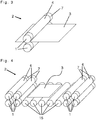
- FIG 5 shows a schematic cross section of a part an inventive treatment device containing the part of the horizontal transport system as shown in Figure 4 .
- one retaining roller pair containing two inventive transport rollers 1 is arranged at the beginning and at the end of a treatment bath. These retaining roller pairs together with a respective weir 11 to accumulate treatment liquid 8, so that the substrate 3 can be transported below the bath level.
- the additional retaining roller pairs each containing two transport rollers 1 ensure to further remove liquid from the surface of the substrate before entering the treatment bath and after having left it.
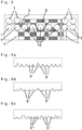
- Figures 6a, 6b and 6c show cut outs of schematic cross sections of the modified surface of different types of inventive transport rollers comparable to the transport roller shown in Figure 1 .
- different types of recesses 6', 6", 6'" are provided.
- Figure 6a shows multiple triangular recesses 6' of irregular size.
- Figure 6b shows rounded recesses 6" of irregular size.
- Figure 6c shows rectangular recesses 6'" of irregular size.
- Figures 7a, 7b and 7c show schematic cross sections and a schematic side view of a transport roller 1' providing a central part 12 and a coating material 13.
- the transport roller 1' contains a coating consisting of an organic polymer providing a modified surface arranged around the transport roller.
- the modified surface is adapted to provide a non-uniform contacting of the substrate, wherein said modified surface contains contact areas adapted to contact the substrate and recesses between the contact areas.
- the transport roller essentially provides the form of a solid body roller it simultaneously provides the possibility to exchange liquids or gases on both sides of the transport roller based on the recesses resulting from the modified surface provided by the coating.
- Figure 8 shows a schematic side view of different types of line shaped recesses 14, 14', 14", 14"', 14"", 14'"'' of preferred embodiments of the present invention.
- Figure 8 shows line shaped recesses 14 as shown in Figure 1 , as well as four different examples of line shaped recesses 14", 14"', 14"", 14'"'' circling the transport roller 1.
- Figure 8 shows line shaped recesses 14', wherein said lines do not circle the transport roller 1, but are essentially parallel to the axis of the transport roller 1.
- the four examples of the line shaped recesses 14", 14"', 14"", 14'"'' not shown in Figure 1 and providing lines circling the transport roller are applied onto transport rollers 1 analog to Figure 1 .
- line shaped recesses 14' being essentially parallel to the axis of the transport roller are applied to an transport roller analog to Figure 1 , wherein line shaped recesses 14' are further characterized in that they provide areas enclosed between the recesses and a contact circle, wherein said areas are at most 12 mm 2 in a cross section perpendicular to the axis of the transport roller 1.
Claims (13)
- Rouleau de transport (1, 1') configuré pour transporter un substrat (3) dans un système de transport horizontal (2),
dans lequel le rouleau de transport (1, 1') a essentiellement la forme d'un rouleau de corps solide, caractérisé en ce que
le rouleau de transport (1, 1') contient en outre une surface modifiée (4) fournissant une entrée en contact non uniforme avec le substrat (3),
dans lequel la surface modifiée (4) contient des zones de contact (5, 5', 5", 5"') pour entrer en contact avec le substrat (3) et des évidements (6, 6', 6", 6"') entre les zones de contact (5, 5', 5", 5"') n'entrant pas en contact avec le substrat,
dans lequel la surface modifiée (4) est adaptée pour fournir un échange de liquide ou de gaz sur les deux côtés du rouleau de transport (1, 1') lors du transport en utilisant le rouleau de transport (1, 1') ; dans lequel la surface modifiée (4) est constituée d'un matériau essentiellement homogène comme un polymère ou un métal, dans lequel ledit matériau homogène n'est pas fait d'un matériau fibreux ou d'une mousse. - Rouleau de transport (1, 1') selon la revendication 1, dans lequel la surface modifiée (4) fournit des évidements de forme linéaire (6, 6', 6", 6"').
- Rouleau de transport (1, 1') selon l'une quelconque des revendications 1 à 2, dans lequel chaque évidement (6, 6', 6", 6"') fournit une surface et une aire est enfermée entre la surface de chaque évidement (6, 6', 6", 6"') et une ligne de contact ou une cercle de contact dans une section transversale, et dans lequel les aires dans une section transversale le long de l'axe du rouleau de transport (1, 1') étant au plus de 5 mm2, les aires dans une section transversale perpendiculaire à l'axe du rouleau de transport (1, 1') sont au plus de 12 mm2, ou les deux, sont équivalent à au moins 90 % de la somme de toutes les aires des évidements (6, 6', 6"", 6"') dans la section transversale correspondante.
- Rouleau de transport (1, 1') selon l'une quelconque des revendications 1 à 3, dans lequel au moins 90 % des zones de contact (5, 5', 5", 5"') de la surface modifiée (4) ont une longueur d'au plus 1,3 cm dans the section transversale le long de l'axe du rouleau de transport (1, 1') ; une longueur d'au plus 0,8 cm dans la section transversale perpendiculaire à l'axe du rouleau de transport (1, 1'), ou les deux, sur la base du nombre des zones de contact dans la section transversale correspondante.
- Rouleau de transport (1, 1') selon l'une quelconque des revendications 1 à 4, dans lequel la surface modifiée (4) fournit une ligne de contact, chaque évidement (6, 6', 6", 6"') fournit une surface et une aire est enfermée entre la surface de chaque évidement (6, 6', 6", 6"') et la ligne de contact dans une section transversale le long de l'axe du rouleau de transport (1, 1'), dans lequel lesdites aires équivalent ensemble à au plus 40 mm2 par longueur en mètre, sur la base de la longueur de la ligne de contact.
- Rouleau de transport (1, 1') selon l'une quelconque des revendications 1 à 5, dans lequel la surface modifiée (4) contient au moins une aire de contact (5, 5', 5", 5"') chaque cm le long de la ligne de contact, chaque cm le long du cercle de contact, ou les deux.
- Rouleau de transport (1, 1') selon l'une quelconque des revendications 1 à 6, dans lequel un quelconque point de contact des zones de contact (5, 5', 5", 5"') fournit une distance jusqu'à un évidement suivant (6, 6', 6", 6"') d'au plus 0,8 cm.
- Rouleau de transport (1, 1') selon l'une quelconque des revendications 1 à 7, dans lequel des zones de contact voisines ont une distance d'au plus 7 mm, et
dans lequel des évidements voisins (6, 6', 6", 6"') ont une distance d'au plus 6 mm. - Système de transport horizontal contenant des rouleaux de transport, dans lequel au moins un rouleau de transport est un rouleau de transport (1, 1') selon l'une quelconque des revendications 1 à 8.
- Système de transport horizontal selon la revendication 9, dans lequel au moins deux rouleaux de transport (1, 1') selon l'une quelconque des revendications 1 à 8 sont agencés sous forme de paire de rouleaux de retenue.
- Dispositif de traitement pour traitement par voie humide, dans lequel le dispositif de traitement contient au moins un rouleau de transport (1, 1') selon l'une quelconque des revendications 1 à 8 ou au moins un système de transport horizontal selon l'une quelconque des revendications 9 et 10.
- Procédé pour traiter un substrat (3), dans lequel le procédé contient l'étape du transport du substrat (3) en utilisant un rouleau de transport (1, 1') selon l'une quelconque des revendications 1 à 8, un système de transport horizontal selon l'une quelconque des revendications 9 et 10 ou un dispositif de traitement selon la revendication 11.
- Utilisation d'un rouleau de transport (1, 1') selon l'une quelconque des revendications 1 à 8 pour transporter un substrat (3) horizontalement.
Priority Applications (9)
| Application Number | Priority Date | Filing Date | Title |
|---|---|---|---|
| EP16199129.4A EP3324426B1 (fr) | 2016-11-16 | 2016-11-16 | Rouleau de transport |
| CN201780070258.0A CN109937472B (zh) | 2016-11-16 | 2017-09-21 | 运输辊 |
| KR1020197015807A KR102413016B1 (ko) | 2016-11-16 | 2017-09-21 | 이송 롤러 |
| JP2019546975A JP7308752B2 (ja) | 2016-11-16 | 2017-09-21 | 搬送ローラー |
| US16/345,747 US11097913B2 (en) | 2016-11-16 | 2017-09-21 | Transport roller |
| MYPI2019002379A MY193744A (en) | 2016-11-16 | 2017-09-21 | Transport roller |
| PCT/EP2017/073933 WO2018091174A1 (fr) | 2016-11-16 | 2017-09-21 | Rouleau de transport |
| TW106136031A TWI661988B (zh) | 2016-11-16 | 2017-10-20 | 運輸輥及其用途、含有運輸輥之水平運輸系統、用於溼處理之處理裝置、及處理一基板之方法 |
| PH12019501083A PH12019501083A1 (en) | 2016-11-16 | 2019-05-15 | Transport roller |
Applications Claiming Priority (1)
| Application Number | Priority Date | Filing Date | Title |
|---|---|---|---|
| EP16199129.4A EP3324426B1 (fr) | 2016-11-16 | 2016-11-16 | Rouleau de transport |
Publications (2)
| Publication Number | Publication Date |
|---|---|
| EP3324426A1 EP3324426A1 (fr) | 2018-05-23 |
| EP3324426B1 true EP3324426B1 (fr) | 2021-05-05 |
Family
ID=57348489
Family Applications (1)
| Application Number | Title | Priority Date | Filing Date |
|---|---|---|---|
| EP16199129.4A Active EP3324426B1 (fr) | 2016-11-16 | 2016-11-16 | Rouleau de transport |
Country Status (9)
| Country | Link |
|---|---|
| US (1) | US11097913B2 (fr) |
| EP (1) | EP3324426B1 (fr) |
| JP (1) | JP7308752B2 (fr) |
| KR (1) | KR102413016B1 (fr) |
| CN (1) | CN109937472B (fr) |
| MY (1) | MY193744A (fr) |
| PH (1) | PH12019501083A1 (fr) |
| TW (1) | TWI661988B (fr) |
| WO (1) | WO2018091174A1 (fr) |
Families Citing this family (1)
| Publication number | Priority date | Publication date | Assignee | Title |
|---|---|---|---|---|
| CN113003223B (zh) * | 2021-04-23 | 2023-06-30 | 成都京东方显示科技有限公司 | 传送装置 |
Family Cites Families (20)
| Publication number | Priority date | Publication date | Assignee | Title |
|---|---|---|---|---|
| DE3708605A1 (de) * | 1987-03-17 | 1988-09-29 | Boettcher Gmbh & Co Felix | Presswalze fuer die entwaesserung von stoffbahnen |
| JPH04129218A (ja) * | 1990-09-19 | 1992-04-30 | Mitsubishi Electric Corp | 水切り装置 |
| JPH08102582A (ja) * | 1994-09-30 | 1996-04-16 | Mitsubishi Paper Mills Ltd | プリント配線基板処理装置 |
| JPH10314684A (ja) * | 1997-05-21 | 1998-12-02 | Speedfam Co Ltd | ディスク形ワークの洗浄方法及び装置 |
| EP0993023A1 (fr) * | 1998-10-05 | 2000-04-12 | Agfa-Gevaert N.V. | Méthode pour le transfert d'un matériel en forme de bande ou de feuille dans une chambre blanche |
| WO2000074115A1 (fr) * | 1999-05-27 | 2000-12-07 | Lam Research Corporation | Nettoyeur de tranches en cascade |
| JP2004299984A (ja) * | 2003-03-31 | 2004-10-28 | Nichias Corp | ディスクロール及びその製造方法 |
| DE102005062528A1 (de) * | 2005-12-16 | 2007-06-21 | Gebr. Schmid Gmbh & Co. | Vorrichtung und Verfahren zur Oberflächenbehandlung von Substraten |
| KR20100049103A (ko) * | 2007-08-06 | 2010-05-11 | 가오 가부시키가이샤 | 액체 도공장치 |
| BRPI0819813A2 (pt) * | 2007-11-19 | 2015-05-26 | Procter & Gamble | Revestimento exterior para um artigo absorvente descartável |
| DE102007061581A1 (de) * | 2007-12-18 | 2009-06-25 | Felix Kunze-Concewitz | Vorrichtung und Verfahren zum Reinigen von Substraten für mikroelektronische Anwendungen durch rotierende Walzen |
| JP5431863B2 (ja) * | 2009-10-19 | 2014-03-05 | 大日本スクリーン製造株式会社 | 基板処理装置 |
| US8684169B2 (en) * | 2010-08-31 | 2014-04-01 | Itoh Denki Co., Ltd. | Transfer device |
| JP5712589B2 (ja) * | 2010-12-07 | 2015-05-07 | セイコーエプソン株式会社 | 印刷装置 |
| KR20130006987A (ko) * | 2011-06-28 | 2013-01-18 | 삼성전기주식회사 | 기판 이송용 롤러 |
| CN202606424U (zh) * | 2012-03-30 | 2012-12-19 | 明基材料有限公司 | 清洁装置 |
| EP2886685A1 (fr) * | 2013-12-20 | 2015-06-24 | ATOTECH Deutschland GmbH | Dispositif destiné à accumuler un liquide de traitement à l'intérieur d'une zone de traitement d'un appareil de traitement horizontal ou galvanique pour un dépôt métallique par voie chimique humide |
| TW201531584A (zh) * | 2013-12-20 | 2015-08-16 | Atotech Deutschland Gmbh | 在用於電流或溼式化學金屬沉積之水平處理裝置之處理區域內積聚處理液之裝置 |
| GB201509080D0 (en) | 2015-05-27 | 2015-07-08 | Landa Labs 2012 Ltd | Coating apparatus |
| DE102016210883A1 (de) * | 2016-06-17 | 2017-12-21 | Singulus Technologies Ag | Vorrichtung und Verfahren zur Behandlung von Substraten unter Verwendung einer Auflagerolle mit porösem Material |
-
2016
- 2016-11-16 EP EP16199129.4A patent/EP3324426B1/fr active Active
-
2017
- 2017-09-21 WO PCT/EP2017/073933 patent/WO2018091174A1/fr active Application Filing
- 2017-09-21 MY MYPI2019002379A patent/MY193744A/en unknown
- 2017-09-21 KR KR1020197015807A patent/KR102413016B1/ko active IP Right Grant
- 2017-09-21 US US16/345,747 patent/US11097913B2/en active Active
- 2017-09-21 JP JP2019546975A patent/JP7308752B2/ja active Active
- 2017-09-21 CN CN201780070258.0A patent/CN109937472B/zh active Active
- 2017-10-20 TW TW106136031A patent/TWI661988B/zh active
-
2019
- 2019-05-15 PH PH12019501083A patent/PH12019501083A1/en unknown
Also Published As
| Publication number | Publication date |
|---|---|
| TW201819269A (zh) | 2018-06-01 |
| EP3324426A1 (fr) | 2018-05-23 |
| US20200055684A1 (en) | 2020-02-20 |
| WO2018091174A1 (fr) | 2018-05-24 |
| PH12019501083A1 (en) | 2019-08-19 |
| JP2019536715A (ja) | 2019-12-19 |
| CN109937472B (zh) | 2023-03-31 |
| MY193744A (en) | 2022-10-27 |
| TWI661988B (zh) | 2019-06-11 |
| KR20190082838A (ko) | 2019-07-10 |
| KR102413016B1 (ko) | 2022-06-23 |
| JP7308752B2 (ja) | 2023-07-14 |
| CN109937472A (zh) | 2019-06-25 |
| US11097913B2 (en) | 2021-08-24 |
Similar Documents
| Publication | Publication Date | Title |
|---|---|---|
| CN105408029B (zh) | 凹版辊及间隔件的制造方法以及间隔件 | |
| EP3324426B1 (fr) | Rouleau de transport | |
| US20080121519A1 (en) | Apparatus for treating flat brittle substrates | |
| US20030132103A1 (en) | Electrolytic processing device and substrate processing apparatus | |
| KR101427554B1 (ko) | 절단용 파형 모노와이어 | |
| JP2013523423A (ja) | 担持ガス分離膜を形成する方法および装置 | |
| CN102472902A (zh) | 偏振膜的贴合装置以及具有该贴合装置的液晶显示装置的制造系统 | |
| US20130040105A1 (en) | Device and method for mechanically texturing a silicon wafer intended to comprise a photovoltaic cell, and resulting silicon wafer | |
| WO2011158594A1 (fr) | Dispositif de transport pour verre en film mince, et procédé de transport d'un verre en film mince | |
| JP7400263B2 (ja) | フィルム、及びフィルムの製造方法 | |
| TWI639545B (zh) | 靜電放電單元,包含其之處理裝置之模組,使用其使基板放電之方法及其用途 | |
| TW201446467A (zh) | 掃刷輥及使用該掃刷輥之塑膠薄膜的製造裝置以及製造方法 | |
| KR102314858B1 (ko) | 필름 이물 제거 장치 및 모듈 | |
| JP2010010210A5 (fr) | ||
| EP3549750B1 (fr) | Feuille composite résistante à la chaleur et procédé de fabrication de ladite feuille | |
| EP3199983B1 (fr) | Feuille optique comprenant un nanomotif et son procédé de fabrication | |
| CN204792738U (zh) | 一种用于太阳能电池制绒机的滚轮 | |
| CN107993963B (zh) | 用于晶圆检测的机械手臂 | |
| KR20160137534A (ko) | 폴리올레핀 미세 다공막 및 폴리올레핀 미세 다공막을 이용하여 이루어지는 코팅용 기재 | |
| CN220796482U (zh) | 电极箔加工装置和电极箔加工系统 | |
| JP6227373B2 (ja) | ゴムシートへの離型剤塗布装置 | |
| JP2019536715A5 (fr) | ||
| KR100750193B1 (ko) | 방향성 결함 분류 방법 및 이를 수행하기 위한 장치 | |
| US20220220627A1 (en) | Substrate sticking and breakage mitigation | |
| KR20170099919A (ko) | 갈바닉 금속 디포지션을 위한 수평 갈바닉 도금 프로세싱 라인의 갈바닉 도금 디바이스 및 그것의 사용 |
Legal Events
| Date | Code | Title | Description |
|---|---|---|---|
| PUAI | Public reference made under article 153(3) epc to a published international application that has entered the european phase |
Free format text: ORIGINAL CODE: 0009012 |
|
| STAA | Information on the status of an ep patent application or granted ep patent |
Free format text: STATUS: THE APPLICATION HAS BEEN PUBLISHED |
|
| AK | Designated contracting states |
Kind code of ref document: A1 Designated state(s): AL AT BE BG CH CY CZ DE DK EE ES FI FR GB GR HR HU IE IS IT LI LT LU LV MC MK MT NL NO PL PT RO RS SE SI SK SM TR |
|
| AX | Request for extension of the european patent |
Extension state: BA ME |
|
| STAA | Information on the status of an ep patent application or granted ep patent |
Free format text: STATUS: REQUEST FOR EXAMINATION WAS MADE |
|
| 17P | Request for examination filed |
Effective date: 20181123 |
|
| RBV | Designated contracting states (corrected) |
Designated state(s): AL AT BE BG CH CY CZ DE DK EE ES FI FR GB GR HR HU IE IS IT LI LT LU LV MC MK MT NL NO PL PT RO RS SE SI SK SM TR |
|
| STAA | Information on the status of an ep patent application or granted ep patent |
Free format text: STATUS: REQUEST FOR EXAMINATION WAS MADE |
|
| GRAP | Despatch of communication of intention to grant a patent |
Free format text: ORIGINAL CODE: EPIDOSNIGR1 |
|
| STAA | Information on the status of an ep patent application or granted ep patent |
Free format text: STATUS: GRANT OF PATENT IS INTENDED |
|
| INTG | Intention to grant announced |
Effective date: 20210225 |
|
| GRAS | Grant fee paid |
Free format text: ORIGINAL CODE: EPIDOSNIGR3 |
|
| GRAA | (expected) grant |
Free format text: ORIGINAL CODE: 0009210 |
|
| STAA | Information on the status of an ep patent application or granted ep patent |
Free format text: STATUS: THE PATENT HAS BEEN GRANTED |
|
| AK | Designated contracting states |
Kind code of ref document: B1 Designated state(s): AL AT BE BG CH CY CZ DE DK EE ES FI FR GB GR HR HU IE IS IT LI LT LU LV MC MK MT NL NO PL PT RO RS SE SI SK SM TR |
|
| REG | Reference to a national code |
Ref country code: GB Ref legal event code: FG4D |
|
| REG | Reference to a national code |
Ref country code: CH Ref legal event code: EP |
|
| REG | Reference to a national code |
Ref country code: AT Ref legal event code: REF Ref document number: 1390871 Country of ref document: AT Kind code of ref document: T Effective date: 20210515 |
|
| REG | Reference to a national code |
Ref country code: IE Ref legal event code: FG4D |
|
| REG | Reference to a national code |
Ref country code: DE Ref legal event code: R096 Ref document number: 602016057271 Country of ref document: DE |
|
| REG | Reference to a national code |
Ref country code: LT Ref legal event code: MG9D |
|
| PG25 | Lapsed in a contracting state [announced via postgrant information from national office to epo] |
Ref country code: LT Free format text: LAPSE BECAUSE OF FAILURE TO SUBMIT A TRANSLATION OF THE DESCRIPTION OR TO PAY THE FEE WITHIN THE PRESCRIBED TIME-LIMIT Effective date: 20210505 Ref country code: FI Free format text: LAPSE BECAUSE OF FAILURE TO SUBMIT A TRANSLATION OF THE DESCRIPTION OR TO PAY THE FEE WITHIN THE PRESCRIBED TIME-LIMIT Effective date: 20210505 Ref country code: BG Free format text: LAPSE BECAUSE OF FAILURE TO SUBMIT A TRANSLATION OF THE DESCRIPTION OR TO PAY THE FEE WITHIN THE PRESCRIBED TIME-LIMIT Effective date: 20210805 Ref country code: HR Free format text: LAPSE BECAUSE OF FAILURE TO SUBMIT A TRANSLATION OF THE DESCRIPTION OR TO PAY THE FEE WITHIN THE PRESCRIBED TIME-LIMIT Effective date: 20210505 |
|
| PG25 | Lapsed in a contracting state [announced via postgrant information from national office to epo] |
Ref country code: RS Free format text: LAPSE BECAUSE OF FAILURE TO SUBMIT A TRANSLATION OF THE DESCRIPTION OR TO PAY THE FEE WITHIN THE PRESCRIBED TIME-LIMIT Effective date: 20210505 Ref country code: SE Free format text: LAPSE BECAUSE OF FAILURE TO SUBMIT A TRANSLATION OF THE DESCRIPTION OR TO PAY THE FEE WITHIN THE PRESCRIBED TIME-LIMIT Effective date: 20210505 Ref country code: NO Free format text: LAPSE BECAUSE OF FAILURE TO SUBMIT A TRANSLATION OF THE DESCRIPTION OR TO PAY THE FEE WITHIN THE PRESCRIBED TIME-LIMIT Effective date: 20210805 Ref country code: PT Free format text: LAPSE BECAUSE OF FAILURE TO SUBMIT A TRANSLATION OF THE DESCRIPTION OR TO PAY THE FEE WITHIN THE PRESCRIBED TIME-LIMIT Effective date: 20210906 Ref country code: PL Free format text: LAPSE BECAUSE OF FAILURE TO SUBMIT A TRANSLATION OF THE DESCRIPTION OR TO PAY THE FEE WITHIN THE PRESCRIBED TIME-LIMIT Effective date: 20210505 Ref country code: GR Free format text: LAPSE BECAUSE OF FAILURE TO SUBMIT A TRANSLATION OF THE DESCRIPTION OR TO PAY THE FEE WITHIN THE PRESCRIBED TIME-LIMIT Effective date: 20210806 Ref country code: LV Free format text: LAPSE BECAUSE OF FAILURE TO SUBMIT A TRANSLATION OF THE DESCRIPTION OR TO PAY THE FEE WITHIN THE PRESCRIBED TIME-LIMIT Effective date: 20210505 Ref country code: IS Free format text: LAPSE BECAUSE OF FAILURE TO SUBMIT A TRANSLATION OF THE DESCRIPTION OR TO PAY THE FEE WITHIN THE PRESCRIBED TIME-LIMIT Effective date: 20210905 |
|
| REG | Reference to a national code |
Ref country code: NL Ref legal event code: MP Effective date: 20210505 |
|
| PG25 | Lapsed in a contracting state [announced via postgrant information from national office to epo] |
Ref country code: NL Free format text: LAPSE BECAUSE OF FAILURE TO SUBMIT A TRANSLATION OF THE DESCRIPTION OR TO PAY THE FEE WITHIN THE PRESCRIBED TIME-LIMIT Effective date: 20210505 |
|
| PG25 | Lapsed in a contracting state [announced via postgrant information from national office to epo] |
Ref country code: SK Free format text: LAPSE BECAUSE OF FAILURE TO SUBMIT A TRANSLATION OF THE DESCRIPTION OR TO PAY THE FEE WITHIN THE PRESCRIBED TIME-LIMIT Effective date: 20210505 Ref country code: SM Free format text: LAPSE BECAUSE OF FAILURE TO SUBMIT A TRANSLATION OF THE DESCRIPTION OR TO PAY THE FEE WITHIN THE PRESCRIBED TIME-LIMIT Effective date: 20210505 Ref country code: EE Free format text: LAPSE BECAUSE OF FAILURE TO SUBMIT A TRANSLATION OF THE DESCRIPTION OR TO PAY THE FEE WITHIN THE PRESCRIBED TIME-LIMIT Effective date: 20210505 Ref country code: DK Free format text: LAPSE BECAUSE OF FAILURE TO SUBMIT A TRANSLATION OF THE DESCRIPTION OR TO PAY THE FEE WITHIN THE PRESCRIBED TIME-LIMIT Effective date: 20210505 Ref country code: CZ Free format text: LAPSE BECAUSE OF FAILURE TO SUBMIT A TRANSLATION OF THE DESCRIPTION OR TO PAY THE FEE WITHIN THE PRESCRIBED TIME-LIMIT Effective date: 20210505 Ref country code: RO Free format text: LAPSE BECAUSE OF FAILURE TO SUBMIT A TRANSLATION OF THE DESCRIPTION OR TO PAY THE FEE WITHIN THE PRESCRIBED TIME-LIMIT Effective date: 20210505 Ref country code: ES Free format text: LAPSE BECAUSE OF FAILURE TO SUBMIT A TRANSLATION OF THE DESCRIPTION OR TO PAY THE FEE WITHIN THE PRESCRIBED TIME-LIMIT Effective date: 20210505 |
|
| REG | Reference to a national code |
Ref country code: DE Ref legal event code: R097 Ref document number: 602016057271 Country of ref document: DE |
|
| RAP4 | Party data changed (patent owner data changed or rights of a patent transferred) |
Owner name: ATOTECH DEUTSCHLAND GMBH & CO. KG |
|
| PLBE | No opposition filed within time limit |
Free format text: ORIGINAL CODE: 0009261 |
|
| STAA | Information on the status of an ep patent application or granted ep patent |
Free format text: STATUS: NO OPPOSITION FILED WITHIN TIME LIMIT |
|
| 26N | No opposition filed |
Effective date: 20220208 |
|
| PG25 | Lapsed in a contracting state [announced via postgrant information from national office to epo] |
Ref country code: IS Free format text: LAPSE BECAUSE OF FAILURE TO SUBMIT A TRANSLATION OF THE DESCRIPTION OR TO PAY THE FEE WITHIN THE PRESCRIBED TIME-LIMIT Effective date: 20210905 Ref country code: AL Free format text: LAPSE BECAUSE OF FAILURE TO SUBMIT A TRANSLATION OF THE DESCRIPTION OR TO PAY THE FEE WITHIN THE PRESCRIBED TIME-LIMIT Effective date: 20210505 |
|
| PG25 | Lapsed in a contracting state [announced via postgrant information from national office to epo] |
Ref country code: MC Free format text: LAPSE BECAUSE OF FAILURE TO SUBMIT A TRANSLATION OF THE DESCRIPTION OR TO PAY THE FEE WITHIN THE PRESCRIBED TIME-LIMIT Effective date: 20210505 |
|
| REG | Reference to a national code |
Ref country code: CH Ref legal event code: PL |
|
| GBPC | Gb: european patent ceased through non-payment of renewal fee |
Effective date: 20211116 |
|
| PG25 | Lapsed in a contracting state [announced via postgrant information from national office to epo] |
Ref country code: LU Free format text: LAPSE BECAUSE OF NON-PAYMENT OF DUE FEES Effective date: 20211116 Ref country code: IT Free format text: LAPSE BECAUSE OF FAILURE TO SUBMIT A TRANSLATION OF THE DESCRIPTION OR TO PAY THE FEE WITHIN THE PRESCRIBED TIME-LIMIT Effective date: 20210505 Ref country code: BE Free format text: LAPSE BECAUSE OF NON-PAYMENT OF DUE FEES Effective date: 20211130 |
|
| REG | Reference to a national code |
Ref country code: BE Ref legal event code: MM Effective date: 20211130 |
|
| PG25 | Lapsed in a contracting state [announced via postgrant information from national office to epo] |
Ref country code: LI Free format text: LAPSE BECAUSE OF NON-PAYMENT OF DUE FEES Effective date: 20211130 Ref country code: CH Free format text: LAPSE BECAUSE OF NON-PAYMENT OF DUE FEES Effective date: 20211130 |
|
| PG25 | Lapsed in a contracting state [announced via postgrant information from national office to epo] |
Ref country code: IE Free format text: LAPSE BECAUSE OF NON-PAYMENT OF DUE FEES Effective date: 20211116 Ref country code: GB Free format text: LAPSE BECAUSE OF NON-PAYMENT OF DUE FEES Effective date: 20211116 |
|
| REG | Reference to a national code |
Ref country code: AT Ref legal event code: UEP Ref document number: 1390871 Country of ref document: AT Kind code of ref document: T Effective date: 20210505 |
|
| PG25 | Lapsed in a contracting state [announced via postgrant information from national office to epo] |
Ref country code: FR Free format text: LAPSE BECAUSE OF NON-PAYMENT OF DUE FEES Effective date: 20211130 |
|
| PG25 | Lapsed in a contracting state [announced via postgrant information from national office to epo] |
Ref country code: HU Free format text: LAPSE BECAUSE OF FAILURE TO SUBMIT A TRANSLATION OF THE DESCRIPTION OR TO PAY THE FEE WITHIN THE PRESCRIBED TIME-LIMIT; INVALID AB INITIO Effective date: 20161116 |
|
| PG25 | Lapsed in a contracting state [announced via postgrant information from national office to epo] |
Ref country code: CY Free format text: LAPSE BECAUSE OF FAILURE TO SUBMIT A TRANSLATION OF THE DESCRIPTION OR TO PAY THE FEE WITHIN THE PRESCRIBED TIME-LIMIT Effective date: 20210505 |
|
| PGFP | Annual fee paid to national office [announced via postgrant information from national office to epo] |
Ref country code: DE Payment date: 20231121 Year of fee payment: 8 Ref country code: AT Payment date: 20231121 Year of fee payment: 8 |
|
| PG25 | Lapsed in a contracting state [announced via postgrant information from national office to epo] |
Ref country code: MK Free format text: LAPSE BECAUSE OF FAILURE TO SUBMIT A TRANSLATION OF THE DESCRIPTION OR TO PAY THE FEE WITHIN THE PRESCRIBED TIME-LIMIT Effective date: 20210505 |