EP3315313B1 - Schreibgerät vom direktflüssigkeitstyp - Google Patents
Schreibgerät vom direktflüssigkeitstyp Download PDFInfo
- Publication number
- EP3315313B1 EP3315313B1 EP16814207.3A EP16814207A EP3315313B1 EP 3315313 B1 EP3315313 B1 EP 3315313B1 EP 16814207 A EP16814207 A EP 16814207A EP 3315313 B1 EP3315313 B1 EP 3315313B1
- Authority
- EP
- European Patent Office
- Prior art keywords
- absorbent body
- ink absorbent
- ink
- communicating tube
- communicating
- Prior art date
- Legal status (The legal status is an assumption and is not a legal conclusion. Google has not performed a legal analysis and makes no representation as to the accuracy of the status listed.)
- Active
Links
Images


Classifications
-
- B—PERFORMING OPERATIONS; TRANSPORTING
- B43—WRITING OR DRAWING IMPLEMENTS; BUREAU ACCESSORIES
- B43K—IMPLEMENTS FOR WRITING OR DRAWING
- B43K5/00—Pens with ink reservoirs in holders, e.g. fountain-pens
- B43K5/18—Arrangements for feeding the ink to the nibs
- B43K5/1818—Mechanical feeding means, e.g. valves; Pumps
-
- B—PERFORMING OPERATIONS; TRANSPORTING
- B43—WRITING OR DRAWING IMPLEMENTS; BUREAU ACCESSORIES
- B43K—IMPLEMENTS FOR WRITING OR DRAWING
- B43K5/00—Pens with ink reservoirs in holders, e.g. fountain-pens
- B43K5/18—Arrangements for feeding the ink to the nibs
-
- B—PERFORMING OPERATIONS; TRANSPORTING
- B43—WRITING OR DRAWING IMPLEMENTS; BUREAU ACCESSORIES
- B43K—IMPLEMENTS FOR WRITING OR DRAWING
- B43K5/00—Pens with ink reservoirs in holders, e.g. fountain-pens
- B43K5/18—Arrangements for feeding the ink to the nibs
- B43K5/1809—Feed bars
-
- B—PERFORMING OPERATIONS; TRANSPORTING
- B43—WRITING OR DRAWING IMPLEMENTS; BUREAU ACCESSORIES
- B43K—IMPLEMENTS FOR WRITING OR DRAWING
- B43K8/00—Pens with writing-points other than nibs or balls
- B43K8/02—Pens with writing-points other than nibs or balls with writing-points comprising fibres, felt, or similar porous or capillary material
- B43K8/04—Arrangements for feeding ink to writing-points
- B43K8/06—Wick feed from within reservoir to writing-points
- B43K8/08—Wick separate from writing-points
Definitions
- JP-A-2006-212884 has disclosed that, when the front end of each of the communicating tubes is inserted from the rear end of the ink absorbent body, the front end of each of the communicating tubes presses the inside of the ink absorbent body frontward so that the high-density portion is formed in the ink absorbent body in the vicinity of the front end of each of the communicating tubes.
- EP 2 554 398 A1 discloses an applicator comprising an application liquid reservoir in which filled application liquid is flowable, an applying body for applying the application liquid, an application liquid-occlusion body located between the application liquid reservoir and the applying body and designed to be impregnated with the application liquid, and a channel forming portion located between the application liquid reservoir and the occlusion body and having a channel in which the application liquid is flowable, wherein the channel forming portion has a protrusion, said protrusion having a cavity inside more than one communication openings communicated with the cavity.
- the front-end region of the connecting part has a plurality of sloped surfaces that goes radially inward toward the front side, and that each of the sloped surfaces of the front-end region of the connecting part is continuously connected to the sloped surface at the front end of each of the communicating tubes.
- each of the communicating tubes has a planar sloped surface.
- a direct liquid type of writing tool of the present invention is defined in appended claim 6.
- the front end of the joint communicating tube has such a configuration that each of the flow paths has the opening in the sloped surface facing toward the outer periphery side of the ink absorbent body, the joint communicating tube has the tip end region adjacent to the opening and extending more frontward than the opening, and the tip end region forms the pressing part configured to press the inside of the ink absorbent body.
- the ink absorbent body is pressed not too much in the vicinity of the tip end region of the joint communicating tube, so that sufficient ink discharging performance from the pen tip can be obtained.
- each of the sloped surfaces may be planar, convexly curved or concavely curved.
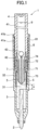
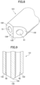
- FIG. 1 is a longitudinal section view of the direct liquid type of writing tool 1 according to the first embodiment of the present invention.
- Fig. 2 is an enlarged longitudinal section view of a main part of Fig. 1 .
- Fig. 3 is a cross section view taken along line A-A of Fig. 2 .
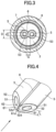
- Fig. 4 is a perspective view of the front end of the communicating tube shown in Fig. 2 .
- a stick part 74 projecting rearward is integrally formed at an axial center at the rear surface of the partition 71.
- the stick part 74 is configured to push a plug 43 of the ink tank 4 rearward, which is explained below.
- the partition 71 has the shape of a disk, and each of the respective communicating tubes 5, the connecting tube 72 and the fitting tubular part 73 has a cylindrical shape.
- the partition 71, the respective communicating tubes 5, the connecting tube 72, the fitting tubular part 73 and the stick part 74 are integrally connected. That is, the partition 71, the respective communicating tubes 5, the connecting tube 72, the fitting tubular part 73 and the stick part 74 are formed as a single piece, as the intermediate member 7.
- a sloped surface 52 is formed at the front end of each of the communicating tubes 5.
- the sloped surface 52 faces toward the outer periphery side of the ink absorbent body 3. That is, the sloped surface 52 has a shape such that the sloped surface 52 goes radially inward toward the front side. In other words, the sloped surface 52 has a shape such that the sloped surface 52 goes towards the axial center of the intermediate member 7 and the axial center of the ink absorbent body 3, toward the front side.
- the sloped surface 52 of the front end of the communicating tube 5 may be planar, convexly curved, concavely curved or the like. In the present embodiment, the planar sloped surface 52 is adopted.
- the front ends of the respective communicating tube 5 and the front end of the connecting part 6 are integrally stuck and inserted into the ink absorbent body 3, frontward from the rear end of the ink absorbent body 3, and positioned in the vicinity of the rear end of the pen tip 2.
- the front ends of the respective communicating tube 5 and the front end of the connecting part 6 are stuck and inserted into the ink absorbent body 3, the front ends of the respective communicating tube 5 and the front end of the connecting part 6 push aside the fabric of the ink absorbent body 3 as well as press the fabric of the ink absorbent body 3 frontward.
- a capillary force is greater in the high-density portion 31 in which the fabric density is higher, and is lower in the low-density portion 32 in which the fabric density is lower.
- the ink in the ink absorbent body 3 can be impregnated preferentially in the high-density portion 31, rather than in the low-density portion 32.
- the ink impregnated in the high-density portion 31 surely liquid-seals the respective openings 51 of the communicating tubes 5. This effectively prevents the ink in the ink tank 4 from leaking from the pen tip 2 too much.
- the front ends of the respective communicating tubes 5 are not directly connected to the rear end of the pen tip 2 (contactless), but can allow the ink to communicate with the pen tip 2 via the inside of the ink absorbent body 3, in particular the high-density portion 31.
- the front ends of the respective communicating tubes 5 are located more rearward than the rear end of the pen tip 2.
- the direct liquid type of writing tool 1 of the present embodiment even if the outer diameter of the barrel 8 is made smaller to make the barrel thinner 8, and thus even if the outer diameter of the ink absorbent body 3 and the distance between the front-end openings 51 of the communicating tubes 5 are made smaller, the ink absorbent body 3 is properly pressed in the vicinity of the front end of each of the communicating tubes 5, so that a proper high-density portion 31 can be formed in the ink absorbent body 3 in the vicinity of the front end of each of the communicating tubes 5. Thus, replacement of the ink and air can be smoothly conducted via the respective communicating tubes 5, so that the ink discharging performance from the pen tip 2 is not deteriorated.
- each of the communicating tubes 5 has the planar sloped surface 52.
- each of the communicating tubes 5 can be more smoothly inserted into the ink absorbent body 3, so that a proper high-density portion 31 can be formed in the ink absorbent body 3 in the vicinity of the front end of each of the communicating tubes 5.
- the ink absorbent body 3 is properly pressed in the vicinity of the tip end region 52d of each of the communicating tubes 5, so that a proper (desired) high-density portion 31 can be formed in the ink absorbent body 3 in the vicinity of the tip end region 52d of each of the communicating tubes 5.
- replacement of the ink and air can be smoothly conducted via the respective communicating tubes 5, so that the ink discharging performance from the pen tip 2 is not deteriorated.
- the tip end regions 52d of the communicating tubes 5 extending more frontward than the respective openings 51 and the region 61d of the connecting tube 6 extending more frontward than the respective openings 51 serve as the pressing part in cooperation.
- the length L of the ridge-like top portion 62 (see Fig. 4 ) is ⁇ mm
- the separation distance G of the two flow paths 53 (see Fig. 3 ) is ⁇ mm. That is, it is important that at least the rectangular region of ⁇ mm ⁇ ⁇ mm when viewed from the front (when viewed in the arrow direction in Fig. 4 ) achieves the pressing function effectively between the two openings 51.
- the length L of the top portion 62 may be selected from a range of 0.5 mm to 4.0 mm, for example.
- the separation distance G between the two flow paths 53 may be selected from a range of 0.5 mm to 3.0 mm, for example.
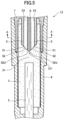
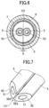
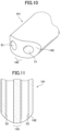
- the two communicating tubes 5 are not connected by a connecting part, but there is a slit-like gap 122 between them.
- the separation width S by the slit-like gap 121 is 0.5 to 2.0 mm.
- the other structure of the second embodiment is substantially the same as that of the direct liquid type of writing tool 1 according to the first embodiment.
- Figs. 5 to 7 the same parts as those of the first embodiment are shown by the same reference numerals, and detailed explanation thereof is omitted.
- Respective sizes of the second embodiment are substantially the same as those of the first embodiment.
- the ink absorbent body 3 is properly pressed in the vicinity of the tip end region 52d of each of the communicating tubes 5, so that a proper (desired) high-density portion 31 can be formed in the ink absorbent body 3 in the vicinity of the tip end region 52d of each of the communicating tubes 5.
- replacement of the ink and air can be smoothly conducted via the respective communicating tubes 5, so that the ink discharging performance from the pen tip 2 is not deteriorated.
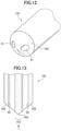
- the front end of the joint communicating tube 131 is located in the ink absorbent body 3, and has such a configuration that each of the flow paths 53 has an opening 51 in a sloped surface 132 facing toward an outer periphery side of the ink absorbent body 3.
- the joint communicating tube 131 has a tip end region 133 adjacent to the respective openings 51 and extending more frontward than the respective openings 51.
- the tip end region 133 forms a pressing part configured to press inside of the ink absorbent body 3 when the joint communicating tube 131 is inserted frontward from a rear end of the ink absorbent body 3.
- the front end of the joint communicating tube 131 is configured to have the two sloped surfaces 132, each of which faces toward the outer periphery side of the ink absorbent body 3, and each of the two flow paths 53 corresponds to each of the two sloped surfaces and has the opening 51 in the corresponding sloped surface 132. Then, the two sloped surfaces 132 are adjacent to each other (intersect to form a certain angle (in this case, 120 degrees: see Fig. 9 ), so that a ridge-like top portion 134 is formed at the foremost end (tip end) of the joint communicating tube 131.
- the top portion 134 of the third embodiment is also located to intersect the axial center of the ink absorbent body 3.
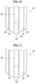
- the front end of the joint communicating tube 141 is located in the ink absorbent body 3, and has such a configuration that each of the flow paths 53 has an opening 51 in a sloped surface 142 facing toward an outer periphery side of the ink absorbent body 3.
- the joint communicating tube 141 has a tip end region 143 adjacent to the respective openings 51 and extending more frontward than the respective openings 51.
- the tip end region 143 forms a pressing part configured to press inside of the ink absorbent body 3 when the joint communicating tube 141 is inserted frontward from a rear end of the ink absorbent body 3.
- the two sloped surfaces 142 are on a smoothly continuous convex curved surface having the same curvature, and no ridge-like top portion is formed at the foremost end (tip end) of the joint communicating tube 141.
- the curvature radius of the continuous two sloped surfaces 142 is for example 3.0 mm.
- the ink absorbent body 3 is pressed not too much in the vicinity of the tip end region 143 of the joint communicating tube 141, so that sufficient ink discharging performance from the pen tip 2 can be obtained.
- the ink absorbent body 3 is properly pressed in the vicinity of the tip end region 143 of the joint communicating tube 141, so that a proper (desired) high-density portion 31 can be formed in the ink absorbent body 3 in the vicinity of the tip end region 143 of the joint communicating tube 141.
- replacement of the ink and air can be smoothly conducted via the respective flow paths 53, so that the ink discharging performance from the pen tip 2 is not deteriorated.
- the diameter of the ink absorbent body 3 is about 5 to 13 mm
- the outer diameter D of the joint communicating tube 151 is about 3.0 to 9.0 mm
- each flow path 53 has a circle shape in transverse section and the diameter d thereof is about 0.5 to 3.0 mm
- the distance a between the top point 154 and the rear end of the pen tip 2 is about 1.0 to 10mm.
- the separation distance G of the two flow paths 53 is ⁇ mm. That is, at least the rectangular region of ⁇ mm ⁇ ⁇ mm when viewed from the front (when viewed in the arrow direction in Fig. 13 ) achieves the pressing function effectively between the two openings 51.
- the separation distance G between the two flow paths 53 may be selected from a range of 0.5 mm to 4.0 mm, for example.
- the other structure of the fifth embodiment is substantially the same as that of the direct liquid type of writing tool according to the third embodiment.
- Figs. 12 and 13 the same parts as those of the third embodiment are shown by the same reference numerals, and detailed explanation thereof is omitted.
- the front end of the joint communicating tube 161 is located in the ink absorbent body 3, and has such a configuration that each of the flow paths 53 has an opening 51 in a sloped surface 162 facing toward an outer periphery side of the ink absorbent body 3.
- the joint communicating tube 161 has a tip end region 163 adjacent to the respective openings 51 and extending more frontward than the respective openings 51.
- the tip end region 163 forms a pressing part configured to press inside of the ink absorbent body 3 when the joint communicating tube 161 is inserted frontward from a rear end of the ink absorbent body 3.
- the ink absorbent body 3 is properly pressed in the vicinity of the tip end region 163 of the joint communicating tube 161, so that a proper (desired) high-density portion 31 can be formed in the ink absorbent body 3 in the vicinity of the tip end region 163 of the joint communicating tube 161.
- replacement of the ink and air can be smoothly conducted via the respective flow paths 53, so that the ink discharging performance from the pen tip 2 is not deteriorated.
- Figs. 20 to 23 are longitudinal section views of the front ends of the respective variations of the communicating tube 131" to 161".
Landscapes
- Engineering & Computer Science (AREA)
- Mechanical Engineering (AREA)
- Pens And Brushes (AREA)
Claims (14)
- Schreibgerät vom Direktflüssigkeitstyp (1), umfassend:eine Stiftspitze (2),einen säulenförmigen, Tinte absorbierenden Körper (3), der mit einem hinteren Ende der Stiftspitze (2) verbunden ist,einen Tintenbehälter (4), der auf einer Rückseite des Tinte absorbierenden Körpers (3) angeordnet ist, undmehrere Verbindungsröhren (5) zum Verbinden des Tinte absorbierenden Körpers (3) und des Tintenbehälters (4),wobeiein vorderes Ende jeder der Verbindungsröhren (5) sich in dem Tinte absorbierenden Körper (3) befindet und so konfiguriert ist, dass es eine geneigte Oberfläche (52) aufweist,jede der Verbindungsröhren (5) eine Öffnung (51) in der geneigten Oberfläche (52) an dem vorderen Ende aufweist,jede der Verbindungsröhren (5) einen Spitzen-Endbereich (52d) aufweist, der an die Öffnung (51) angrenzt und sich weiter nach vorne erstreckt als die Öffnung (51), undwobeider Spitzen-Endbereich (52d) ein Druckteil bildet, das konfiguriert ist, in das Innere des Tinte absorbierenden Körpers (3) zu drücken, wenn jede der Verbindungsröhren (5) von einem hinteren Ende des Tinte absorbierenden Körpers (3) nach vorne eingeführt wird, dadurch gekennzeichnet, dassjede geneigte Oberfläche (52) in Richtung einer Außenumfangsseite des Tinte absorbierenden Körpers (3) zeigt und radial nach innen in Richtung der Vorderseite verläuft, und die Öffnung (51) des vorderen Endes jeder der Verbindungsröhren (5) radial nach außen zeigt.
- Schreibgerät vom Direktflüssigkeitstyp (1) gemäß Anspruch 1, wobei die jeweiligen Seitenwände der Verbindungsröhren (5) durch ein Verbindungsteil (6) verbunden sind.
- Schreibgerät vom Direktflüssigkeitstyp (1) gemäß Anspruch 2, wobei sich ein vorderer Endbereich (61d) des Verbindungsteils (6) weiter nach vorne erstreckt als die Öffnung (51) von jeder der Verbindungsröhren (5), um so zusammen mit dem Spitzen-Endbereich (52d) einer jeden der Verbindungsröhren (5) das Druckteil zu bilden.
- Schreibgerät vom Direktflüssigkeitstyp (1) gemäß Anspruch 2 oder Anspruch 3, wobei der vordere Endbereich (61d) des Verbindungsteils (6) eine oder mehrere geneigte Verbindungsteil-Oberflächen (61) fortlaufend von der geneigten Oberfläche (52) jeder der Verbindungsröhren (5) aufweist.
- Schreibgerät vom Direktflüssigkeitstyp (1) gemäß einem der Ansprüche 1 bis 4, wobei die Anzahl der Verbindungsröhren (5) zwei beträgt.
- Schreibgerät vom Direktflüssigkeitstyp (12), umfassend:eine Stiftspitze (2),einen säulenförmigen, Tinte absorbierenden Körper (3), der mit einem hinteren Ende der Stiftspitze (2) verbunden ist,einen Tintenbehälter (4), der auf einer Rückseite des Tinte absorbierenden Körpers (3) angeordnet ist, undeine gemeinsame Verbindungsröhre (131), die mehrere Strömungswege (53) aufweist, zum Verbinden des Tinte absorbierenden Körpers (3) und des Tintenbehälters (4),wobeiein vorderes Ende der gemeinsamen Verbindungsröhre (131) sich in dem Tinte absorbierenden Körper (3) befindet und eine solche Konfiguration aufweist, dass jeder der Strömungswege (53) eine Öffnung (51) in einer geneigten Oberfläche (132) aufweist,die gemeinsame Verbindungsröhre (131) einen Spitzen-Endbereich (133) aufweist, der an die Öffnung (51) angrenzt und sich weiter nach vorne als die Öffnung (51) erstreckt, undder Spitzen-Endbereich (133) ein Druckteil bildet, das konfiguriert ist, in das Innere des Tinte absorbierenden Körpers (3) zu drücken, wenn die gemeinsame Verbindungsröhre (131) von einem hinteren Ende des Tinte absorbierenden Körpers (3) nach vorne eingeführt wird,dadurch gekennzeichnet, dass jede geneigte Oberfläche (132) in Richtung einer Außenumfangsseite des Tinte absorbierenden Körpers (3) zeigt und radial nach innen in Richtung der Vorderseite verläuft und die Öffnung (51) eines jeden der Strömungswege (53) der gemeinsamen Verbindungsröhre (5) radial nach außen zeigt.
- Schreibgerät vom Direktflüssigkeitstyp (12) gemäß Anspruch 6, wobei das vordere Ende der gemeinsamen Verbindungsröhre (131) so konfiguriert ist, dass es mehrere geneigte Oberflächen (132) aufweist, von denen jede in Richtung der Außenumfangsseite des Tinte absorbierenden Körpers (3) zeigt, und wobei jeder der Strömungswege (53) jeder der mehreren geneigten Oberflächen (132) entspricht und die Öffnung (51) in der entsprechenden geneigten Oberfläche (132) aufweist.
- Schreibgerät vom Direktflüssigkeitstyp (12) gemäß Anspruch 7, wobei die Anzahl der Strömungswege (53) zwei beträgt.
- Schreibgerät vom Direktflüssigkeitstyp (12) gemäß Anspruch 8, wobei das vordere Ende der gemeinsamen Verbindungsröhre (131) die Form eines rotierenden Körpers rotationssymmetrisch um eine Achse aufweist.
- Schreibgerät vom Direktflüssigkeitstyp (12) gemäß Anspruch 9, wobei das vordere Ende der gemeinsamen Verbindungsröhre (131) die Form eines konischen oder kegelstumpfförmigen Körpers aufweist.
- Schreibgerät vom Direktflüssigkeitstyp (12) gemäß Anspruch 9, wobei das vordere Ende der gemeinsamen Verbindungsröhre (131) die Form eines Teils eines kugelförmigen Körpers aufweist.
- Schreibgerät vom Direktflüssigkeitstyp (1), umfassend:eine Stiftspitze (2),einen säulenförmigen, Tinte absorbierenden Körper (3), der mit einem hinteren Ende der Stiftspitze (2) verbunden ist,einen Tintenbehälter (4), der auf einer Rückseite des Tinte absorbierenden Körpers (3) angeordnet ist, undeine Verbindungsröhre (5) zum Verbinden des Tinte absorbierenden Körpers (3) und des Tintenbehälters (4),wobeidie Stiftspitze (2) mit einer axialen Mitte des Tinte absorbierenden Körpers (3) ausgerichtet ist,ein vorderes Ende der Verbindungsröhre (5) sich in dem Tinte absorbierenden Körper (3) befindet und eine solche Konfiguration aufweist, dass jede der mehreren Öffnungen (51) in einer geneigten Oberfläche (52), die in Richtung einer Außenumfangsseite des Tinte absorbierenden Körpers (3) zeigt, geöffnet ist, wobei die geneigte Oberfläche (52) radial nach innen in Richtung der Vorderseite verläuft und jede der mehreren Öffnungen (51) des vorderen Endes der Verbindungsröhre (5) radial nach außen zeigt,die Verbindungsröhre (5) einen Spitzen-Endbereich (52d) aufweist, der an die Öffnung (51) angrenzt und sich weiter nach vorne erstreckt als die Öffnung (51), undwobeider Spitzen-Endbereich (52d) keine Öffnung (51) aufweist, die mit der axialen Mitte des Tinte absorbierenden Körpers (3) ausgerichtet ist, und ein Druckteil bildet, das konfiguriert ist, in das Innere des Tinte absorbierenden Körpers (3) zu drücken, wenn die Verbindungsröhre (5) von einem hinteren Ende des Tinte absorbierenden Körpers (3) nach vorne eingeführt wird, dadurch gekennzeichnet, dassdas vordere Ende der Verbindungsröhre (5) so konfiguriert ist, dass es mehrere geneigte Oberflächen (52) aufweist, von denen jede in Richtung der Außenumfangsseite des Tinte absorbierenden Körpers (3) zeigt, undjede der mehreren Öffnungen (51) jeder der mehreren geneigten Oberflächen (52) entspricht und in der entsprechenden geneigten Oberfläche (52) geöffnet ist.
- Schreibgerät vom Direktflüssigkeitstyp (1) gemäß Anspruch 12, wobei die Anzahl der Öffnungen (51) zwei beträgt.
- Schreibgerät vom Direktflüssigkeitstyp (1), umfassend:eine Stiftspitze (2),einen säulenförmigen, Tinte absorbierenden Körper (3), der mit einem hinteren Ende der Stiftspitze (2) verbunden ist,einen Tintenbehälter (4), der auf einer Rückseite des Tinte absorbierenden Körpers (3) angeordnet ist, undeine Verbindungsröhre (5) zum Verbinden des Tinte absorbierenden Körpers (3) und des Tintenbehälters (4),wobeidie Stiftspitze (2) mit einer axialen Mitte des Tinte absorbierenden Körpers (3) ausgerichtet ist,ein vorderes Ende der Verbindungsröhre (5) sich in dem Tinte absorbierenden Körper (3) befindet und eine solche Konfiguration aufweist, dass jede der mehreren Öffnungen (51) in einer geneigten Oberfläche (52) geöffnet ist, die in Richtung einer Außenumfangsseite des Tinte absorbierenden Körpers (3) zeigt, wobei die geneigte Oberfläche (52) radial nach innen in Richtung der Vorderseite verläuft und jede der mehreren Öffnungen (51) des vorderen Endes der Verbindungsröhre (5) radial nach außen zeigt,die Verbindungsröhre (5) einen Spitzen-Endbereich (52d) aufweist, der an die Öffnung (51) angrenzt und sich weiter nach vorne erstreckt als die Öffnung (51), undwobeider Spitzen-Endbereich (52d) keine Öffnung (51) aufweist, die mit der axialen Mitte des Tinte absorbierenden Körpers (3) ausgerichtet ist, und ein Druckteil bildet, das konfiguriert ist, in das Innere des Tinte absorbierenden Körpers (3) zu drücken, wenn die Verbindungsröhre (5) von einem hinteren Ende des Tinte absorbierenden Körpers (3) nach vorne eingeführt wird, dadurch gekennzeichnet, dassdas vordere Ende der Verbindungsröhre (5) die Form eines rotierenden Körpers rotationssymmetrisch um eine Achse aufweist.
Applications Claiming Priority (2)
| Application Number | Priority Date | Filing Date | Title |
|---|---|---|---|
| JP2015129296 | 2015-06-26 | ||
| PCT/JP2016/067528 WO2016208436A1 (ja) | 2015-06-26 | 2016-06-13 | 直液式筆記具 |
Publications (3)
| Publication Number | Publication Date |
|---|---|
| EP3315313A1 EP3315313A1 (de) | 2018-05-02 |
| EP3315313A4 EP3315313A4 (de) | 2019-03-13 |
| EP3315313B1 true EP3315313B1 (de) | 2025-04-09 |
Family
ID=57585673
Family Applications (1)
| Application Number | Title | Priority Date | Filing Date |
|---|---|---|---|
| EP16814207.3A Active EP3315313B1 (de) | 2015-06-26 | 2016-06-13 | Schreibgerät vom direktflüssigkeitstyp |
Country Status (8)
| Country | Link |
|---|---|
| US (1) | US10569595B2 (de) |
| EP (1) | EP3315313B1 (de) |
| JP (1) | JP6768649B2 (de) |
| KR (1) | KR102530257B1 (de) |
| CN (1) | CN107709034B (de) |
| BR (1) | BR112017027535B1 (de) |
| TW (1) | TWI687325B (de) |
| WO (1) | WO2016208436A1 (de) |
Families Citing this family (8)
| Publication number | Priority date | Publication date | Assignee | Title |
|---|---|---|---|---|
| TWI621540B (zh) * | 2017-05-19 | 2018-04-21 | Sdi Corp | 書寫工具及其輸墨單元 |
| TWI645987B (zh) * | 2017-09-18 | 2019-01-01 | 順德工業股份有限公司 | 書寫工具 |
| JP2020001352A (ja) * | 2018-06-29 | 2020-01-09 | 株式会社パイロットコーポレーション | ボールペン |
| CN108725021A (zh) * | 2018-07-25 | 2018-11-02 | 德清县扬烨制笔有限公司 | 直液式书写笔 |
| CN112888576A (zh) * | 2018-09-20 | 2021-06-01 | 波雷克斯科技公司 | 非均质纤维流体储存器 |
| CN111109664B (zh) | 2020-01-15 | 2023-12-26 | 深圳麦克韦尔科技有限公司 | 一种电子雾化装置及其雾化器 |
| KR20220167536A (ko) | 2021-06-14 | 2022-12-21 | 정지우 | 광고용커버를 구성한 병뚜껑 |
| KR20220167544A (ko) | 2021-06-14 | 2022-12-21 | 정지우 | 이종 약을 수용한 병뚜껑 |
Family Cites Families (17)
| Publication number | Priority date | Publication date | Assignee | Title |
|---|---|---|---|---|
| TW385760U (en) * | 1998-10-21 | 2000-03-21 | Mcaide Entpr Company Ltd | Pen |
| JP2000233592A (ja) * | 1999-02-17 | 2000-08-29 | Pilot Ink Co Ltd | 直液式筆記具 |
| JP2002120486A (ja) * | 2000-10-16 | 2002-04-23 | Pilot Ink Co Ltd | 直液式筆記具 |
| KR100562280B1 (ko) * | 2004-06-15 | 2006-03-23 | 주식회사모나미 | 필기구 |
| CN101274565B (zh) * | 2004-09-14 | 2010-04-07 | 百乐墨水株式会社 | 直液式笔具 |
| JP4537864B2 (ja) | 2005-02-02 | 2010-09-08 | パイロットインキ株式会社 | 直液式筆記具 |
| KR100932571B1 (ko) * | 2004-09-14 | 2009-12-17 | 파일롯트 잉크 가부시키가이샤 | 직액식 필기구 |
| JP4750590B2 (ja) * | 2006-03-13 | 2011-08-17 | パイロットインキ株式会社 | 直液式筆記具 |
| KR100946428B1 (ko) | 2006-03-09 | 2010-03-10 | 파일롯트 잉크 가부시키가이샤 | 직액식 필기구 |
| CN100509438C (zh) * | 2006-03-09 | 2009-07-08 | 百乐墨水株式会社 | 直液式书写工具 |
| JP4820701B2 (ja) * | 2006-07-19 | 2011-11-24 | パイロットインキ株式会社 | 直液式筆記具 |
| CN101224690A (zh) * | 2007-01-20 | 2008-07-23 | 王良 | 标记工具 |
| JP5085952B2 (ja) * | 2007-02-19 | 2012-11-28 | パイロットインキ株式会社 | 直液式筆記具 |
| JP5687529B2 (ja) * | 2010-03-26 | 2015-03-18 | 株式会社サクラクレパス | 塗布具 |
| JP5700817B2 (ja) * | 2011-05-19 | 2015-04-15 | 株式会社サクラクレパス | 塗布具 |
| BR112015023848B1 (pt) | 2013-03-20 | 2020-11-10 | Kabushiki Kaisha Pilot Corporation (Also Trading As Pilot Corporation) | instrumento de escrita e cartucho de tinta |
| CA2924950C (en) * | 2013-09-23 | 2021-07-06 | Kabushiki Kaisha Pilot Corporation (Also Trading As Pilot Corporation) | Writing instrument and ink cartridge |
-
2016
- 2016-06-13 BR BR112017027535-0A patent/BR112017027535B1/pt active IP Right Grant
- 2016-06-13 US US15/738,147 patent/US10569595B2/en active Active
- 2016-06-13 CN CN201680037774.9A patent/CN107709034B/zh active Active
- 2016-06-13 JP JP2017525219A patent/JP6768649B2/ja active Active
- 2016-06-13 KR KR1020187002145A patent/KR102530257B1/ko active Active
- 2016-06-13 EP EP16814207.3A patent/EP3315313B1/de active Active
- 2016-06-13 WO PCT/JP2016/067528 patent/WO2016208436A1/ja not_active Ceased
- 2016-06-23 TW TW105119790A patent/TWI687325B/zh active
Also Published As
| Publication number | Publication date |
|---|---|
| EP3315313A4 (de) | 2019-03-13 |
| JP6768649B2 (ja) | 2020-10-14 |
| US20180186172A1 (en) | 2018-07-05 |
| WO2016208436A1 (ja) | 2016-12-29 |
| KR102530257B1 (ko) | 2023-05-09 |
| KR20180021113A (ko) | 2018-02-28 |
| EP3315313A1 (de) | 2018-05-02 |
| BR112017027535B1 (pt) | 2022-02-15 |
| US10569595B2 (en) | 2020-02-25 |
| TWI687325B (zh) | 2020-03-11 |
| BR112017027535A2 (de) | 2018-08-21 |
| TW201706145A (zh) | 2017-02-16 |
| CN107709034B (zh) | 2019-09-10 |
| CN107709034A (zh) | 2018-02-16 |
| JPWO2016208436A1 (ja) | 2018-04-19 |
Similar Documents
| Publication | Publication Date | Title |
|---|---|---|
| EP3315313B1 (de) | Schreibgerät vom direktflüssigkeitstyp | |
| EP3050712B1 (de) | Schreibinstrument und tintenpatrone | |
| CN100509438C (zh) | 直液式书写工具 | |
| HK1250503B (zh) | 书写工具用笔芯及书写工具 | |
| EP1634724B1 (de) | Tintenverschlusselement in einem Schreibgerät | |
| JP2008183896A (ja) | 直液式筆記具 | |
| JP4537864B2 (ja) | 直液式筆記具 | |
| JP3152082U (ja) | 直液式筆記具 | |
| JP4943950B2 (ja) | 直液式筆記具 | |
| JP2008023755A (ja) | 直液式筆記具 | |
| JP4848067B2 (ja) | 直液式筆記具 | |
| JP7402442B2 (ja) | 液体供給体およびこの液体供給体を備える塗布具 | |
| CN104837643A (zh) | 再充填插塞释放组合件及包括其的书写工具 | |
| JP5129058B2 (ja) | 直液式筆記具 | |
| JP3751378B2 (ja) | 塗布具の筆穂取付構造 | |
| JP5085952B2 (ja) | 直液式筆記具 | |
| JP3152083U (ja) | 直液式筆記具 | |
| JP4943956B2 (ja) | 直液式筆記具 | |
| JP2020001352A (ja) | ボールペン | |
| BR112018010461B1 (pt) | Cartucho de tinta e instrumento de escrita | |
| JP2008023877A (ja) | 直液式筆記具 | |
| JP6481466B2 (ja) | 塗布具 | |
| JP2008044285A (ja) | 直液式筆記具 | |
| JP4943951B2 (ja) | 直液式筆記具 | |
| JP2009012191A (ja) | 直液式筆記具 |
Legal Events
| Date | Code | Title | Description |
|---|---|---|---|
| STAA | Information on the status of an ep patent application or granted ep patent |
Free format text: STATUS: THE INTERNATIONAL PUBLICATION HAS BEEN MADE |
|
| PUAI | Public reference made under article 153(3) epc to a published international application that has entered the european phase |
Free format text: ORIGINAL CODE: 0009012 |
|
| STAA | Information on the status of an ep patent application or granted ep patent |
Free format text: STATUS: REQUEST FOR EXAMINATION WAS MADE |
|
| 17P | Request for examination filed |
Effective date: 20180116 |
|
| AK | Designated contracting states |
Kind code of ref document: A1 Designated state(s): AL AT BE BG CH CY CZ DE DK EE ES FI FR GB GR HR HU IE IS IT LI LT LU LV MC MK MT NL NO PL PT RO RS SE SI SK SM TR |
|
| AX | Request for extension of the european patent |
Extension state: BA ME |
|
| DAV | Request for validation of the european patent (deleted) | ||
| DAX | Request for extension of the european patent (deleted) | ||
| A4 | Supplementary search report drawn up and despatched |
Effective date: 20190211 |
|
| RIC1 | Information provided on ipc code assigned before grant |
Ipc: B43K 5/18 20060101ALI20190205BHEP Ipc: B43K 8/04 20060101AFI20190205BHEP |
|
| STAA | Information on the status of an ep patent application or granted ep patent |
Free format text: STATUS: EXAMINATION IS IN PROGRESS |
|
| 17Q | First examination report despatched |
Effective date: 20210504 |
|
| GRAP | Despatch of communication of intention to grant a patent |
Free format text: ORIGINAL CODE: EPIDOSNIGR1 |
|
| STAA | Information on the status of an ep patent application or granted ep patent |
Free format text: STATUS: GRANT OF PATENT IS INTENDED |
|
| INTG | Intention to grant announced |
Effective date: 20241105 |
|
| P01 | Opt-out of the competence of the unified patent court (upc) registered |
Free format text: CASE NUMBER: APP_67295/2024 Effective date: 20241219 |
|
| GRAS | Grant fee paid |
Free format text: ORIGINAL CODE: EPIDOSNIGR3 |
|
| GRAA | (expected) grant |
Free format text: ORIGINAL CODE: 0009210 |
|
| STAA | Information on the status of an ep patent application or granted ep patent |
Free format text: STATUS: THE PATENT HAS BEEN GRANTED |
|
| AK | Designated contracting states |
Kind code of ref document: B1 Designated state(s): AL AT BE BG CH CY CZ DE DK EE ES FI FR GB GR HR HU IE IS IT LI LT LU LV MC MK MT NL NO PL PT RO RS SE SI SK SM TR |
|
| REG | Reference to a national code |
Ref country code: GB Ref legal event code: FG4D |
|
| REG | Reference to a national code |
Ref country code: CH Ref legal event code: EP |
|
| REG | Reference to a national code |
Ref country code: DE Ref legal event code: R096 Ref document number: 602016091857 Country of ref document: DE |
|
| REG | Reference to a national code |
Ref country code: IE Ref legal event code: FG4D |
|
| PGFP | Annual fee paid to national office [announced via postgrant information from national office to epo] |
Ref country code: DE Payment date: 20250618 Year of fee payment: 10 |
|
| PGFP | Annual fee paid to national office [announced via postgrant information from national office to epo] |
Ref country code: GB Payment date: 20250618 Year of fee payment: 10 |
|
| PGFP | Annual fee paid to national office [announced via postgrant information from national office to epo] |
Ref country code: FR Payment date: 20250625 Year of fee payment: 10 |
|
| REG | Reference to a national code |
Ref country code: NL Ref legal event code: MP Effective date: 20250409 |
|
| PG25 | Lapsed in a contracting state [announced via postgrant information from national office to epo] |
Ref country code: NL Free format text: LAPSE BECAUSE OF FAILURE TO SUBMIT A TRANSLATION OF THE DESCRIPTION OR TO PAY THE FEE WITHIN THE PRESCRIBED TIME-LIMIT Effective date: 20250409 |
|
| REG | Reference to a national code |
Ref country code: AT Ref legal event code: MK05 Ref document number: 1783222 Country of ref document: AT Kind code of ref document: T Effective date: 20250409 |
|
| PG25 | Lapsed in a contracting state [announced via postgrant information from national office to epo] |
Ref country code: ES Free format text: LAPSE BECAUSE OF FAILURE TO SUBMIT A TRANSLATION OF THE DESCRIPTION OR TO PAY THE FEE WITHIN THE PRESCRIBED TIME-LIMIT Effective date: 20250409 Ref country code: PT Free format text: LAPSE BECAUSE OF FAILURE TO SUBMIT A TRANSLATION OF THE DESCRIPTION OR TO PAY THE FEE WITHIN THE PRESCRIBED TIME-LIMIT Effective date: 20250811 Ref country code: FI Free format text: LAPSE BECAUSE OF FAILURE TO SUBMIT A TRANSLATION OF THE DESCRIPTION OR TO PAY THE FEE WITHIN THE PRESCRIBED TIME-LIMIT Effective date: 20250409 |
|
| REG | Reference to a national code |
Ref country code: LT Ref legal event code: MG9D |
|
| PG25 | Lapsed in a contracting state [announced via postgrant information from national office to epo] |
Ref country code: NO Free format text: LAPSE BECAUSE OF FAILURE TO SUBMIT A TRANSLATION OF THE DESCRIPTION OR TO PAY THE FEE WITHIN THE PRESCRIBED TIME-LIMIT Effective date: 20250709 Ref country code: GR Free format text: LAPSE BECAUSE OF FAILURE TO SUBMIT A TRANSLATION OF THE DESCRIPTION OR TO PAY THE FEE WITHIN THE PRESCRIBED TIME-LIMIT Effective date: 20250710 |
|
| PG25 | Lapsed in a contracting state [announced via postgrant information from national office to epo] |
Ref country code: PL Free format text: LAPSE BECAUSE OF FAILURE TO SUBMIT A TRANSLATION OF THE DESCRIPTION OR TO PAY THE FEE WITHIN THE PRESCRIBED TIME-LIMIT Effective date: 20250409 |
|
| PG25 | Lapsed in a contracting state [announced via postgrant information from national office to epo] |
Ref country code: BG Free format text: LAPSE BECAUSE OF FAILURE TO SUBMIT A TRANSLATION OF THE DESCRIPTION OR TO PAY THE FEE WITHIN THE PRESCRIBED TIME-LIMIT Effective date: 20250409 |
|
| PG25 | Lapsed in a contracting state [announced via postgrant information from national office to epo] |
Ref country code: HR Free format text: LAPSE BECAUSE OF FAILURE TO SUBMIT A TRANSLATION OF THE DESCRIPTION OR TO PAY THE FEE WITHIN THE PRESCRIBED TIME-LIMIT Effective date: 20250409 |
|
| PG25 | Lapsed in a contracting state [announced via postgrant information from national office to epo] |
Ref country code: AT Free format text: LAPSE BECAUSE OF FAILURE TO SUBMIT A TRANSLATION OF THE DESCRIPTION OR TO PAY THE FEE WITHIN THE PRESCRIBED TIME-LIMIT Effective date: 20250409 |
|
| PG25 | Lapsed in a contracting state [announced via postgrant information from national office to epo] |
Ref country code: RS Free format text: LAPSE BECAUSE OF FAILURE TO SUBMIT A TRANSLATION OF THE DESCRIPTION OR TO PAY THE FEE WITHIN THE PRESCRIBED TIME-LIMIT Effective date: 20250709 |
|
| PG25 | Lapsed in a contracting state [announced via postgrant information from national office to epo] |
Ref country code: IS Free format text: LAPSE BECAUSE OF FAILURE TO SUBMIT A TRANSLATION OF THE DESCRIPTION OR TO PAY THE FEE WITHIN THE PRESCRIBED TIME-LIMIT Effective date: 20250809 |
|
| PG25 | Lapsed in a contracting state [announced via postgrant information from national office to epo] |
Ref country code: LV Free format text: LAPSE BECAUSE OF FAILURE TO SUBMIT A TRANSLATION OF THE DESCRIPTION OR TO PAY THE FEE WITHIN THE PRESCRIBED TIME-LIMIT Effective date: 20250409 |
|
| REG | Reference to a national code |
Ref country code: DE Ref legal event code: R097 Ref document number: 602016091857 Country of ref document: DE |
|
| PG25 | Lapsed in a contracting state [announced via postgrant information from national office to epo] |
Ref country code: SM Free format text: LAPSE BECAUSE OF FAILURE TO SUBMIT A TRANSLATION OF THE DESCRIPTION OR TO PAY THE FEE WITHIN THE PRESCRIBED TIME-LIMIT Effective date: 20250409 Ref country code: DK Free format text: LAPSE BECAUSE OF FAILURE TO SUBMIT A TRANSLATION OF THE DESCRIPTION OR TO PAY THE FEE WITHIN THE PRESCRIBED TIME-LIMIT Effective date: 20250409 |
|
| PG25 | Lapsed in a contracting state [announced via postgrant information from national office to epo] |
Ref country code: CZ Free format text: LAPSE BECAUSE OF FAILURE TO SUBMIT A TRANSLATION OF THE DESCRIPTION OR TO PAY THE FEE WITHIN THE PRESCRIBED TIME-LIMIT Effective date: 20250409 |
|
| PG25 | Lapsed in a contracting state [announced via postgrant information from national office to epo] |
Ref country code: EE Free format text: LAPSE BECAUSE OF FAILURE TO SUBMIT A TRANSLATION OF THE DESCRIPTION OR TO PAY THE FEE WITHIN THE PRESCRIBED TIME-LIMIT Effective date: 20250409 |
|
| PG25 | Lapsed in a contracting state [announced via postgrant information from national office to epo] |
Ref country code: RO Free format text: LAPSE BECAUSE OF FAILURE TO SUBMIT A TRANSLATION OF THE DESCRIPTION OR TO PAY THE FEE WITHIN THE PRESCRIBED TIME-LIMIT Effective date: 20250409 Ref country code: SK Free format text: LAPSE BECAUSE OF FAILURE TO SUBMIT A TRANSLATION OF THE DESCRIPTION OR TO PAY THE FEE WITHIN THE PRESCRIBED TIME-LIMIT Effective date: 20250409 |
|
| REG | Reference to a national code |
Ref country code: CH Ref legal event code: H13 Free format text: ST27 STATUS EVENT CODE: U-0-0-H10-H13 (AS PROVIDED BY THE NATIONAL OFFICE) Effective date: 20260127 |
|
| PG25 | Lapsed in a contracting state [announced via postgrant information from national office to epo] |
Ref country code: IT Free format text: LAPSE BECAUSE OF FAILURE TO SUBMIT A TRANSLATION OF THE DESCRIPTION OR TO PAY THE FEE WITHIN THE PRESCRIBED TIME-LIMIT Effective date: 20250409 |
|
| PG25 | Lapsed in a contracting state [announced via postgrant information from national office to epo] |
Ref country code: MC Free format text: LAPSE BECAUSE OF FAILURE TO SUBMIT A TRANSLATION OF THE DESCRIPTION OR TO PAY THE FEE WITHIN THE PRESCRIBED TIME-LIMIT Effective date: 20250409 |
|
| PLBE | No opposition filed within time limit |
Free format text: ORIGINAL CODE: 0009261 |
|
| STAA | Information on the status of an ep patent application or granted ep patent |
Free format text: STATUS: NO OPPOSITION FILED WITHIN TIME LIMIT |
|
| PG25 | Lapsed in a contracting state [announced via postgrant information from national office to epo] |
Ref country code: LU Free format text: LAPSE BECAUSE OF NON-PAYMENT OF DUE FEES Effective date: 20250613 |
|
| REG | Reference to a national code |
Ref country code: CH Ref legal event code: L10 Free format text: ST27 STATUS EVENT CODE: U-0-0-L10-L00 (AS PROVIDED BY THE NATIONAL OFFICE) Effective date: 20260218 |
|
| REG | Reference to a national code |
Ref country code: BE Ref legal event code: MM Effective date: 20250630 |
|
| 26N | No opposition filed |
Effective date: 20260112 |
|
| PG25 | Lapsed in a contracting state [announced via postgrant information from national office to epo] |
Ref country code: IE Free format text: LAPSE BECAUSE OF NON-PAYMENT OF DUE FEES Effective date: 20250613 |
|
| PG25 | Lapsed in a contracting state [announced via postgrant information from national office to epo] |
Ref country code: BE Free format text: LAPSE BECAUSE OF NON-PAYMENT OF DUE FEES Effective date: 20250630 |