EP3305241B1 - Reinigungswerkzeug für zahnzwischenräume - Google Patents
Reinigungswerkzeug für zahnzwischenräume Download PDFInfo
- Publication number
- EP3305241B1 EP3305241B1 EP16807539.8A EP16807539A EP3305241B1 EP 3305241 B1 EP3305241 B1 EP 3305241B1 EP 16807539 A EP16807539 A EP 16807539A EP 3305241 B1 EP3305241 B1 EP 3305241B1
- Authority
- EP
- European Patent Office
- Prior art keywords
- base portion
- cleaning
- core base
- recesses
- recess
- Prior art date
- Legal status (The legal status is an assumption and is not a legal conclusion. Google has not performed a legal analysis and makes no representation as to the accuracy of the status listed.)
- Active
Links
Images


Classifications
-
- A—HUMAN NECESSITIES
- A61—MEDICAL OR VETERINARY SCIENCE; HYGIENE
- A61C—DENTISTRY; APPARATUS OR METHODS FOR ORAL OR DENTAL HYGIENE
- A61C15/00—Devices for cleaning between the teeth
- A61C15/02—Toothpicks
-
- A—HUMAN NECESSITIES
- A46—BRUSHWARE
- A46B—BRUSHES
- A46B15/00—Other brushes; Brushes with additional arrangements
- A46B15/0093—Magazins or sets of brushes components, e.g. plurality of brushes linked as a package
-
- A—HUMAN NECESSITIES
- A46—BRUSHWARE
- A46B—BRUSHES
- A46B3/00—Brushes characterised by the way in which the bristles are fixed or joined in or on the brush body or carrier
- A46B3/005—Bristle carriers and bristles moulded as a unit
-
- A—HUMAN NECESSITIES
- A46—BRUSHWARE
- A46B—BRUSHES
- A46B5/00—Brush bodies; Handles integral with brushware
- A46B5/002—Brush bodies; Handles integral with brushware having articulations, joints or flexible portions
- A46B5/0025—Brushes with elastically deformable heads that change shape during use
- A46B5/0029—Head made of soft plastics, rubber or rubber inserts in plastics matrix
-
- A—HUMAN NECESSITIES
- A46—BRUSHWARE
- A46B—BRUSHES
- A46B9/00—Arrangements of the bristles in the brush body
- A46B9/02—Position or arrangement of bristles in relation to surface of the brush body, e.g. inclined, in rows, in groups
- A46B9/04—Arranged like in or for toothbrushes
-
- B—PERFORMING OPERATIONS; TRANSPORTING
- B29—WORKING OF PLASTICS; WORKING OF SUBSTANCES IN A PLASTIC STATE IN GENERAL
- B29C—SHAPING OR JOINING OF PLASTICS; SHAPING OF MATERIAL IN A PLASTIC STATE, NOT OTHERWISE PROVIDED FOR; AFTER-TREATMENT OF THE SHAPED PRODUCTS, e.g. REPAIRING
- B29C45/00—Injection moulding, i.e. forcing the required volume of moulding material through a nozzle into a closed mould; Apparatus therefor
- B29C45/14—Injection moulding, i.e. forcing the required volume of moulding material through a nozzle into a closed mould; Apparatus therefor incorporating preformed parts or layers, e.g. injection moulding around inserts or for coating articles
- B29C45/14065—Positioning or centering articles in the mould
-
- B—PERFORMING OPERATIONS; TRANSPORTING
- B29—WORKING OF PLASTICS; WORKING OF SUBSTANCES IN A PLASTIC STATE IN GENERAL
- B29C—SHAPING OR JOINING OF PLASTICS; SHAPING OF MATERIAL IN A PLASTIC STATE, NOT OTHERWISE PROVIDED FOR; AFTER-TREATMENT OF THE SHAPED PRODUCTS, e.g. REPAIRING
- B29C45/00—Injection moulding, i.e. forcing the required volume of moulding material through a nozzle into a closed mould; Apparatus therefor
- B29C45/16—Making multilayered or multicoloured articles
- B29C45/1676—Making multilayered or multicoloured articles using a soft material and a rigid material, e.g. making articles with a sealing part
-
- B—PERFORMING OPERATIONS; TRANSPORTING
- B29—WORKING OF PLASTICS; WORKING OF SUBSTANCES IN A PLASTIC STATE IN GENERAL
- B29C—SHAPING OR JOINING OF PLASTICS; SHAPING OF MATERIAL IN A PLASTIC STATE, NOT OTHERWISE PROVIDED FOR; AFTER-TREATMENT OF THE SHAPED PRODUCTS, e.g. REPAIRING
- B29C45/00—Injection moulding, i.e. forcing the required volume of moulding material through a nozzle into a closed mould; Apparatus therefor
- B29C45/17—Component parts, details or accessories; Auxiliary operations
- B29C45/26—Moulds
- B29C45/2626—Moulds provided with a multiplicity of narrow cavities connected to a common cavity, e.g. for brushes, combs
-
- A—HUMAN NECESSITIES
- A46—BRUSHWARE
- A46B—BRUSHES
- A46B2200/00—Brushes characterized by their functions, uses or applications
- A46B2200/10—For human or animal care
- A46B2200/1066—Toothbrush for cleaning the teeth or dentures
- A46B2200/108—Inter-dental toothbrush, i.e. for cleaning interdental spaces specifically
-
- A—HUMAN NECESSITIES
- A46—BRUSHWARE
- A46B—BRUSHES
- A46B5/00—Brush bodies; Handles integral with brushware
- A46B5/002—Brush bodies; Handles integral with brushware having articulations, joints or flexible portions
- A46B5/0033—Brush bodies; Handles integral with brushware having articulations, joints or flexible portions bending or stretching or collapsing
- A46B5/0037—Flexible resilience by plastic deformation of the material
-
- B—PERFORMING OPERATIONS; TRANSPORTING
- B29—WORKING OF PLASTICS; WORKING OF SUBSTANCES IN A PLASTIC STATE IN GENERAL
- B29C—SHAPING OR JOINING OF PLASTICS; SHAPING OF MATERIAL IN A PLASTIC STATE, NOT OTHERWISE PROVIDED FOR; AFTER-TREATMENT OF THE SHAPED PRODUCTS, e.g. REPAIRING
- B29C45/00—Injection moulding, i.e. forcing the required volume of moulding material through a nozzle into a closed mould; Apparatus therefor
- B29C45/14—Injection moulding, i.e. forcing the required volume of moulding material through a nozzle into a closed mould; Apparatus therefor incorporating preformed parts or layers, e.g. injection moulding around inserts or for coating articles
- B29C45/14065—Positioning or centering articles in the mould
- B29C2045/14147—Positioning or centering articles in the mould using pins or needles penetrating through the insert
Definitions
- the present invention relates to an interdental cleaning tool having a cleaning portion covered with an elastomer.
- an interdental cleaning tool including a base portion made of a synthetic resin and a soft portion made of an elastomer, in which the base portion includes a handle base portion and a core base portion provided at a tip end of the handle base portion and having an elongated shaft shape, the soft portion includes at least a cleaning soft portion covering the core base portion, the handle base portion forms a handle portion as a grip, and the core base portion and the cleaning soft portion form a cleaning portion for cleaning a space between teeth (see, e.g., Patent Literatures 1 to 5).
- a method widely used to manufacture the interdental cleaning tool includes: filling a synthetic resin material into a first molding space of a first die to form a base portion; placing, in a second molding space of a second die, the base portion molded in the first die; and filling an elastomeric material into the second molding space to form a soft portion in a state of positioning and holding a core base portion at a central part of the second molding space by plural sets of holding pins provided in a first mold and second mold of the second die in a manner of being opposite to each other at an interval in a length direction (axial direction of the core base portion) of the second molding space, so that the interdental cleaning tool is obtained.
- a plurality of interdental cleaning tools are also molded simultaneously by a method that includes: providing a first die having a plurality of first molding spaces and a second die having the same number of second molding spaces as the first molding spaces; in manufacturing the interdental cleaning tools, supplying a synthetic resin material to the first molding spaces to simultaneously form a plurality of base portions so that the plurality of base portions can be connected to one another by a runner portion; placing, in the second molding spaces of the second die, a primary molded product made of the plurality of base portions connected to one another by the runner portion; and then filling an elastomeric material into the plurality of second molding spaces, so that a plurality of interdental cleaning tools are simultaneously formed.
- Patent Literature 6 describes a method for manufacturing an interdental cleaning tool.
- the interdental cleaning tool comprises: a base part made of a synthetic resin, the base part having a handle base and an elongated shaft-like core base connected to a leading end of the handle base; and a flexible part made of an elastomer and covering at least a portion of the base part, the flexible part having at least a cleaning flexible part covering the core base, the handle base constituting a handle part, and the core base and the cleaning flexible part constituting an interdental cleaning part.
- Patent Literature 7 describes a brush, in particular an interdental brush, which comprises a bristle-carrying stem 18 defining a longitudinal direction 22 and having an elongate support core 24, a bristle area 26 having bristles 20 projecting from the bristle-carrying stem 18, and a neck element 32 connecting the support core 24 to a handle 16', wherein the handle 16', the support core 24 and the neck element 32 are injection moulded integrally from a first plastics component, and wherein a second plastics component in the form of an integral layer and the bristles 20 projecting therefrom is mounted on the support core 24.
- glass fiber is added to the synthetic resin material forming the base portion.
- strength and rigidity of the core base portion in the axial direction of the core is increased. This improves the insertability into an interdental portion.
- a stronger force is required to insert the interdental cleaning tool since the core base portion has difficulty in warping. This causes a large bending load to easily act on the core base portion during cleaning spaces between the molars, and thus the core base portion breaks at an intermediate portion in the length direction.
- the core base portion becomes easy to warp and the breakage of the cleaning portion can be suppressed.
- a high injection temperature is essential, and a cooling time after injection molding becomes long. This causes the productivity of the interdental cleaning tool to be lowered, and material cost is also high. This considerably increases total manufacturing cost. There has been such a problem.
- the inventors of the present invention have found out the following as causes of the breakage of the core base portion.
- a recess is likely to be formed at a position where the holding pin for positioning the core base portion in the second die during molding of the cleaning soft portion and the core base portion are in contact with each other.
- a cross-sectional area of the core base portion becomes smaller at the position of this recess, and a stress generated by application of bending force to the core base portion becomes higher.
- the recess is formed by the following mechanism. That is, the base portion molded by the first die is placed in the second die after being cooled, and in order to shorten a molding time, the base portion is placed in the second die in a relatively high temperature state. In addition, the base portion placed in the second die is softened during molding of the cleaning soft portion since the base portion is exposed to the high-temperature elastomer filled in the second molding space. In the second die, the plural sets of holding pins are allowed to protrude into the second molding space by a preset protruding length, and the core base portion is positioned at the central part of the second molding space.
- the molding time is shortened, causing variations in molding dimensions of the core base portion.
- the core base portion is exposed to the high temperature, causing thermal expansion thereof.
- the core base portion may vibrate at the time of filling the elastomer. With these, it can be presumed that the tip end portion of the holding pin bites into the core base portion and the recess is formed in the core base portion.
- the handle portion when the handle portion is formed into a flat shape in order to facilitate gripping with fingers, the handle portion is usually formed to be flat with respect to a mold opening and closing direction of the first die and the second die, and the holding pins are provided so that an axial direction of the holding pins can be disposed in the mold opening and closing direction of the second die in order to simplify a structure of the dies as much as possible.
- the inventors of the present invention have found that, in the I-type interdental cleaning tool, when the space between the molars is cleaned by gripping the handle portion, the recess of the core base portion, which is formed by each of the holding pins is disposed in each of an outer peripheral side of the curved core base portion and an inner peripheral side thereof, and concentration of a large stress occurs in the vicinity of each of recesses on the inner and outer peripheral sides, so that the core base portion is easily broken.
- An object of the present invention is to provide an interdental cleaning tool which has a simple configuration and can effectively prevent the occurrence of the breakage of the core base portion at the time of inserting the interdental cleaning tool into interdental spaces or during interdental cleaning without reducing the productivity of the interdental cleaning tool.
- the present invention relates to an interdental cleaning tool as defined in claim 1. Embodiments of the invention are recited in the dependent claims.
- first side portion and second side portion of the cleaning portion mean one half of an outer peripheral surface of the cleaning portion, which is molded by one of dies, and a remaining half of the outer peripheral surface of the cleaning portion, which is molded by other die, in a second die for molding the cleaning portion.
- the cleaning portion recesses other than the cleaning portion recesses formed at an interval in the axial direction of the cleaning portion can be formed so as to face each other with the core base portion interposed therebetween.
- the cleaning portion recesses of the second side portion which are paired with the cleaning portion recesses of the first side portion, mean cleaning portion recesses located at the same order positions counted from the tip end of the cleaning portion.
- the interval in the axial direction of the cleaning portion refers to a shortest distance when ends of two recesses are connected to each other in the axial direction of the cleaning portion.
- the interval is obtained by the following procedure. First, a plane (BS in FIG. 19 ) including UL and a center line (CL in FIG. 19 ) of the core base portion is set. Next, perpendicular lines are drawn to CL from the intersections (B, T in FIG. 19 ) of the respective recesses of the first side portion and the second side portion and the BS, and intersections of the perpendicular lines and CL are obtained.
- One is selected from the obtained two points on the CL in the first side portion, one is selected from two points on the CL in the second side portion, and a length between both of the points on the CL is obtained. Since there are four combinations, the number of lengths obtained above is four. A shortest length among the obtained four lengths is defined as the "interval in the axial direction of the cleaning portion" between the two recesses which do not overlap each other in the circumferential direction.
- there are two types of recesses which are a cleaning portion recess and a core base portion recess. The recesses are obtained by replacing the above-described "recess" with the recesses desired to be obtained.
- a synthetic resin material is filling into a first molding space of a first die to mold a base portion, the base portion molded in the first die is placed in a second molding space of a second die, and an elastomeric material is filled into the second molding space to form a soft portion in a state of holding a core base portion at a central part of the second molding space with plural sets of holding pins provided in a first mold and second mold of the second die at an interval in a length direction of the second molding space.
- the cleaning portion recesses are formed at positions where the tip end portions of the holding pins contact the core base portion, and further, on the core base portion, the plural sets of core base portion recesses, which are formed by receiving abutment of the tip end portions of the holding pins, are generated at intervals in the axial direction of the core base portion.
- At least one set of two cleaning portion recesses out of plural sets of the cleaning portion recesses, each pair of which is formed between the first side portion and the second side portion, are formed at an interval in the axial direction of the cleaning portion so as not to overlap each other in the circumferential direction of the cleaning portion. Accordingly, the core base portion recesses are formed alternately on the first side portion and second side portion of the core base portion during molding of the soft portion, and a pair of the core base portion recesses can be prevented from being formed at the same position in the axial direction of the core base portion.
- a cross-sectional area of the core base portion at a position corresponding to each of the core base portion recesses becomes larger than that of the holding pins which overlap each other in the circumferential direction, and the occurrence of the breakage of the core base portion can be prevented.
- a portion in the axial direction of the core base portion, where the core base portion is subjected to the force becomes longer in comparison with the case of disposing the holding pins which overlap each other in the circumferential direction.
- the core base portion is more firmly held, and the core base portion recesses 14Ea formed during the molding of the soft portion 20 is suppressed from being deepened.
- the cross-sectional area of the core base portion 12 at each of the positions corresponding to the core base portion recesses 14Ea is increased, and the occurrence of breakage of the core base portion 12 can be prevented.
- the interval between the holding pins in the length direction of the core base portion is substantially shortened, it is possible to hold the core base portion satisfactorily stably. For this reason, the core base portion can be effectively prevented from being broken at the time of insertion into the space between the teeth or during interdental cleaning while constituting the base portion with a synthetic resin material having excellent productivity.
- a straight line (UL in FIG. 19 ) is first set, which connects points (points B and T in FIG. 19 ) of a plane (BS in FIG. 19 ) passing through a longitudinal center line (CL in FIG. 19 ) of the core base portion and ends of each of the core base portion recesses to each other.
- a perpendicular line (DL in FIG. 19 ) drawn to CL from an arbitrary point of UL is set.
- the "depth of the core base portion recess” means a length of a straight line (DLa in FIG. 19 ) that connects an intersection (C1 in FIG. 19 ) of this DL with the UL, and an intersection (C2 in FIG.
- the core base portion recess means a degree of deformation (distance at which the core base portion is compressed and deformed) of the core base portion, the deformation being caused by the fact that the holding pins abut against the core base portion during molding in the second die.
- the "cross-sectional area of the core base portion” means an area of the core base portion in a plane (VS in FIG. 19 ) perpendicular to the axial central axis (CL in FIG. 19 ) of the core base portion.
- the "position corresponding to the core base portion recess” means a range (position) of the straight line CL in which the core base portion recess is included in the plane VS.
- the aforementioned at least one set of the cleaning portion recesses formed at the interval in the axial direction of the cleaning portion has therebetween an interval in the axial direction of the cleaning portion, the interval being set to one fourth or more of a maximum axial length of the cleaning portion recesses.
- the cleaning portion recesses are arranged so as to be substantially uniformly, or narrowed as approaching to a tip end side of the cleaning portion, in the axial direction of the cleaning portion, on each of the first side portion and the second side portion. That is, the tip end portion of the cleaning portion is a substantially linear and elongated shaft-shaped structure configured to have a smaller diameter than that of a base end portion, and is liable to structurally change with respect to the force applied by the molding when the cleaning soft portion is molded.
- the arrangement interval of the cleaning portion recesses is set so as to become narrower as approaching to the tip end side of the cleaning portion, or is set to be substantially uniform, as in the present invention, it is easy to suppress the core base portion from moving from a predetermined position during molding of the soft portion.
- the arrangement interval of the cleaning portion recesses in the axial direction of the cleaning portion is set substantially uniform. Such a configuration is more preferable since external force applied to the core base portion during the molding of the soft portion is likely to be uniform.
- the plurality of core base portion recesses have opening areas that are set to be substantially identical in size to one another, or are set so that an opening area of the core base portion recess on a most tip end side among the plurality of core base portion recesses is smallest, on each of the first side portion and the second side portion.
- the "opening area of the core base portion recess" means an area where the holding pin and the core base portion are in contact during the molding using the second dies.
- the opening area of the core base portion recess can be confirmed as an area of a portion (CS in FIG.
- the core base portion is an elongated conical structure, and the cross-sectional area thereof becomes smaller as approaching to the tip end side, it is preferable to set the opening area at the tip end portion, where the cross sectional area is the smallest, to be the smallest.
- the tip end portion area of the holding pin located at the most tip end side of the core base portion is substantially identical in size to one another or smallest as compared with the tip end portion areas of the holding pins at the other positions.
- the opening area of the core base portion recess on the most tip end side of the core base portion is set to be as small as possible, that is, the tip end portion area of the holding pin on the tip end side is reduced, whereby a passage area of the second molding space is made as large as possible. Then, a flow resistance of the elastomeric material can be set as small as possible.
- the influence of the Karman vortex, which is generated in the vicinity of each holding pin, on the molded product and the holding pin can be further suppressed, holding of the core base portion can be improved, and poor filling of the elastomeric material with respect to the cleaning soft portion molding portion can be prevented.
- the aforementioned at least one of the plurality of cleaning portion recesses has the core base portion recess that has an opening shape elongated in the axial direction of the cleaning portion in each case of the cleaning portion recesses formed at an interval in the axial direction of the cleaning portion so as not to overlap each other in the circumferential direction of the cleaning portion and of the cleaning portion recesses formed so as to overlap each other in the circumferential direction of the cleaning portion.
- Formation of the core base portion recesses with this shape can be realized by matching a shape of such a pin tip of the holding pin at the corresponding position with the shape of the core base portion recesses to be formed.
- the pin tip shape of the holding pin is circular
- a diameter of the pin tip of the holding pin is reduced, reducing the area of each of the core base portion recesses.
- the diameter of the pin tip of the holding pin is reduced, reducing the contact area of the holding pin with respect to the core base portion. Accordingly, the depth of the core base portion recess tends to be deepened, and stress concentration tends to occur at a position where each of the core base portion recesses is provided.
- fixed regions of the core base portion are reduced, requiring a pressing force of the holding pins to rise in order to firmly fix the core base portion.
- Each of the core base portion recesses is formed into the shape elongated in the axial direction of the cleaning portion, whereby the degree of freedom in arrangement layout of the cleaning protrusions is improved.
- the holding pins of the first side portion and the second side portion with respect to the core base portion apply forces to different positions of the core base portion, vibrations of the core base portion during molding of the soft portion can be suppressed as compared with the case of holding pins having a circular shape with the same area.
- the depth of the core base portion recess formed during molding the soft portion can be made shallow, and the stress concentration at the position of the cleaning portion, where the core base portion recess exists during use can be effectively prevented. Accordingly, this configuration is preferable.
- the cleaning portion recesses be formed at intervals in the axial direction of the cleaning portion so as not to overlap each other in the circumferential direction of the cleaning portion.
- the "shape elongated in the axial direction of the cleaning portion” means a shape having a maximum length in a direction of the center line (CL in FIG.
- the "shape elongated in the axial direction of the cleaning portion” includes such a shape elongated in the spiral direction of the cleaning portion shaft as an elliptical shape, an oblong shape, a rectangular shape, an egg shape, an oval shape and a bale shape (rectangular shape with curved short side portions, rectangular shape with rounded corners), a teardrop shape, and a parallelogram shape.
- the core base portion recess elongated in the axial direction has a maximum axial length of 0.4 mm or more and 1.5 mm or less, or 0.6 mm or more and 1.0 mm or less.
- the cleaning portion recesses having the core base portion recesses having the shape elongated in the axial direction can also be formed individually on the first side portion and second side portion of the cleaning portion, which correspond to a predetermined spot within a range of 5.5 mm to 7.0 mm from the tip end of the core base portion.
- the core base portion recesses has a maximum depth of set to 0.01 mm or more and 0.085 mm or less, in each case of the cleaning portion recesses formed at an interval in the axial direction of the cleaning portion so as not to overlap each other in the circumferential direction of the cleaning portion and of the cleaning portion recesses formed so as to overlap each other in the circumferential direction of the cleaning portion.
- the reduction of the cross-sectional area of the core base portion at the forming position of the core base portion recess is suppressed, and the occurrence of the stress concentration in the core base portion recess is suppressed.
- a recessed structure exists at a position where the stress concentrates, it becomes difficult to influence a change in the structure of the core base portion, so that the breakage of the core base portion at the time of the insertion into the space between the teeth or during the interdental cleaning can be prevented effectively.
- the core base portion can be effectively prevented from being broken at the time of insertion into the space between the teeth or during interdental cleaning while constituting the base portion with a synthetic resin material having excellent productivity.
- the maximum depth of the core base portion recess means a largest distance (maximum value of the depth of the core base portion recess) among shortest distances from the outer surface to the bottom surface of the opening portion of the core base portion recess.
- the straight line (UL in FIG. 19 ) is first set, which connects the contact points (points B and T in FIG. 19 ) of the plane (BS in FIG. 19 ) passing through the longitudinal center line (CL in FIG.
- a perpendicular line (DL in FIG. 19 ) drawn to CL from an arbitrary point of UL is set. There is measured the length of the straight line (DLa in FIG. 19 ) that connects the intersection (C1 in FIG. 19 ) of this DL and the UL and the intersection (C2 in FIG. 19 ) of this DL and the bottom surface (CS in FIG. 19 ) of the core base portion recess to each other.
- the measurement of the length of DLa is performed between the point B and the point T (on the straight line UL) while rotating the BS around the CL, and a maximum value of the obtained numerical value DLa is defined as the "maximum depth of the core base portion recess".
- the remaining sets of cleaning portion recesses are provided opposite to each other with the core base portion interposed therebetween, or are disposed so as to be shifted in the axial direction of the core base portion within a range equal to or less than the diameter of the holding pins.
- the contact area of the holding pins with respect to the core base portion increases, the vibrations of the core base portion during molding of the soft portion can be suppressed, and it becomes easy to perform control to make the depth of the core base portion recess shallow. Therefore, the occurrence of the stress concentration at the positions of the core base portion recesses during the interdental cleaning can be prevented effectively. Accordingly, this configuration is preferable.
- the number of the cleaning portion recesses of the first side portion and the second side portion may be the same or different. For example, the number of the cleaning portion recesses can be reduced by only one on the first side portion than on the second side portion.
- the handle base portion and the core base portion are disposed on substantially the identical axis.
- a plurality of the interdental cleaning tools can be molded to be closely arranged side by side in parallel, and the number of the interdental cleaning tools to be taken can be increased. Accordingly, this is preferable.
- the base portion is made of a thermoplastic synthetic resin material having crystallinity in which a melting point is 150°C or more.
- the production efficiency is increased by shortening a molding time of the base portion, particularly a cooling time thereof, whereby the productivity of the interdental cleaning tool can be improved, and eventually, manufacturing cost of the interdental cleaning tool can be reduced.
- a maximum cross-sectional area of the core base portion at the position corresponding to the core base portion recess is 55.0 to 99.6%, preferably 70.0 to 99.0%, most preferably 80.0 to 97.9% with respect to the cross-sectional area of the core base portion at a position adjacent to the core base portion recess, in each case of the cleaning portion recesses formed at an interval in the axial direction of the cleaning portion so as not to overlap each other in the circumferential direction of the cleaning portion and of the cleaning portion recesses formed so as to overlap each other in the circumferential direction of the cleaning portion.
- the stress concentration in each of the core base portion recesses is reduced, and the breakage of the core base portion at the time of the insertion into the interdental space or during the interdental cleaning can be prevented far more effectively.
- the "cross-sectional area of the core base portion” means an area of a portion where the plane (VS in FIG. 19 ) perpendicular to the center line (CL in FIG. 19 ) of the core base portion is in contact with the core base portion.
- the "position adjacent to the core base portion recess” means an intersection position of the axial center line (CL) of the core base portion in FIG. 19 and the plane VS perpendicular to the CL when the plane VS has only one contact point with the end of the core base portion recess.
- the "position corresponding to the core base portion recess” means an intersection position of the axial center line (CL) of the core base portion and the plane VS perpendicular to the CL when the plane VS has a contact point with the end of the core base portion recess. That is, a straight line on the CL that connects the above two "positions adjacent to the core base portion recess" corresponds to the two points.
- At least one set of the cleaning portion recesses out of plural sets of the cleaning portion recesses paired with each other between the first side portion and the second side portion has a central segment in a depth direction, which passes through centers of the at least one set of the cleaning portion recesses, and is formed with an angle in the circumferential direction of the cleaning portion with respect to a mold opening and closing direction of the dies for molding the cleaning soft portion, among the cleaning portion recesses formed at intervals in the axial direction of the cleaning portion so as not to overlap each other in the circumferential direction of the cleaning portion, and the cleaning portion recesses including other recesses if the other recesses are present.
- the degree of freedom in arrangement layout of the cleaning protrusions can be improved.
- the cleaning portion recesses are molded by holding pins which hold the core base portion in the central part of the second molding space. Since the positions of the holding pins can be adjusted in the length direction and the circumferential direction with respect to the second molding space so that the holding pins do not interfere with the forming positions of the cleaning protrusions, the degree of freedom in the arrangement layout of the cleaning protrusions can be improved.
- the interdental cleaning tool according to any one of (1) to (14), at least either one of a fibrous material and talc is added to the synthetic resin material constituting the base portion.
- strength and rigidity of the core base portion against the bending force can be increased, and insertability of the cleaning portion with respect to the interdental space can be improved.
- the rigidity of the core base portion can be increased, the depth of the recesses formed in the core base portion becomes difficult to deepen, and this is also preferable in preventing the occurrence of the stress concentration at the position where the core base portion recess is provided.
- an interdental cleaning tool that includes a base portion made of a synthetic resin; and a soft portion made of an elastomer that covers at least a part of the base portion, the base portion including a handle base portion and a core base portion having an elongated shaft-shape connecting continuously to a tip end portion of the handle base portion, the soft portion having at least a cleaning soft portion that covers the core base portion, the handle base portion constituting a handle portion serving as a grip, and the core base portion and the cleaning soft portion constituting a cleaning portion for interdental cleaning.
- the method includes: a base portion molding step of supplying a synthetic resin material into a first molding space of a first die to form a base portion; and a soft portion molding step of placing the base portion molded in the base portion molding step in a second molding space of a second die for molding the soft portion, and filling the second molding space with an elastomeric material to form a soft portion in a state of holding the core base portion in a substantially central part of a cleaning soft portion molding portion by plural sets of holding pins paired between a first mold and second mold of the second die, the holding pins provided in the second die at intervals in a length direction of the second molding space.
- an interdental cleaning tool in which at least one set of the plural sets of holding pins are arranged at an interval in the length direction of the second molding space so as not to overlap each other in a circumferential direction of the second molding space.
- one set of the holding pins paired between the first mold and second mold of the second die means, for example, holding pins of the first mold and the second mold, which are located at the same order positions counted from the tip end of the second molding space.
- At least one set of the plural sets of holding pins are arranged at an interval in the length direction of the second molding space so as not to overlap each other in a circumferential direction of the second molding space. Accordingly, the core base portion recesses formed by the holding pins are alternately arranged in the length direction of the core base portion on the first side portion and second side portion of the core base portion, and a pair of the core base portion recesses are prevented from being formed at the same axial position of the core base portion. Therefore, the cross-sectional area of the core base portion at the position corresponding to the core base portion recess is increased, and the occurrence of the breakage of the core base portion can be prevented.
- the holding pins of the first side portion and the second side portion apply a force to different positions of the core base portion, so that vibrations of the core base portion during molding of the soft portion can be suppressed, as compared with the case of the holding pins which overlap each other in the circumferential direction. Therefore, the depth of the formed core base portion recesses becomes shallow, the cross-sectional area of the core base portion at each of the positions corresponding to the core base portion recesses is increased, and the occurrence of the breakage of the core base portion can be prevented. Furthermore, since the interval between the holding pins with respect to the length direction of the core base portion is substantially shortened, it is possible to hold the core base portion satisfactorily stably.
- the plural sets of holding pins are individually arranged at interval in the length direction of the second molding space so as not to overlap each other in the circumferential direction of the second molding space.
- all sets of the cleaning portion recesses formed by the holding pins can be individually formed at intervals in the axial direction of the cleaning portion so as not to overlap each other in the circumferential direction of the cleaning portion, the breakage of the cleaning portion can be prevented far more effectively.
- the contact area of the holding pins with respect to the core base portion increases, the vibrations of the core base portion during molding of the soft portion can be suppressed, and the core base portion recesses to be formed can be suppressed from being deepened. Therefore, the depth of the core base portion recesses during the interdental cleaning is made shallow, whereby the occurrence of the stress concentration at the positions of the core base portion recesses during the interdental cleaning can be prevented effectively. Accordingly, this configuration is preferable.
- the number of the holding pins of the first mold and the second mold in the second die can be the same or different. For example, the number of the holding pins can be reduced by only one on the first mold than on the second mold.
- an arrangement interval of the holding pins in the length direction of the second molding space is set to be substantially uniform or to become narrower as approaching to the tip end side of the second molding space in both of the first side portion and the second side portion, in each case where the holding pins are arranged at intervals in the length direction of the second molding space so as not to overlap each other in the circumferential direction of the second molding space, and where the holding pins which overlap each other in the circumferential direction of the second molding space are arranged.
- the tip end portion of the cleaning portion is such a substantially linear and elongated shaft-shaped structure configured to have a smaller diameter than the base end portion, and is liable to structurally change with respect to a molding force when the cleaning soft portion is molded.
- the arrangement interval of the holding pins may be set so as to become narrower as approaching to the tip end side of the second molding space, or may be set to be substantially uniform. Then, it is easy to suppress the core base portion from moving from a predetermined position during molding of the soft portion.
- cross-sectional areas of the tip end portions of the plurality of holding pins and vicinities thereof are set to be substantially identical in size to one another, or are set to be smallest in the holding pin on the most tip end side of the second molding space, in each case where the holding pins are arranged at intervals in the length direction of the second molding space so as not to overlap each other in the circumferential direction of the second molding space, and where the holding pins which overlap each other in the circumferential direction of the second molding space are arranged.
- the passage area of the second molding space that molds the cleaning soft portion becomes narrower as approaching to the tip end side.
- the cross-sectional area (area of cross section perpendicular to the axial direction of each of the holding pins) of the tip end portion of the holding pin and the vicinity thereof is reduced, whereby the cross-sectional area of the entire holding pin can also be reduced.
- the passage area can be set as large as possible, whereby a flow resistance of the elastomeric material can be set as small as possible.
- the influence of the Karman vortex, which is generated in the vicinity of each holding pin, on the molded product and the holding pin can be further suppressed, the holding of the core base portion can be improved, and the poor filling of the elastomeric material into the cleaning soft portion molding portion can be prevented.
- the cross-sectional area of the tip end portion of the holding pin has very little change in area due to shaking or expansion and shrinkage during molding, therefore, even if these factors are taken into consideration, it can be presumed that the cross-sectional area becomes substantially the same as an area of the opening portion of the cleaning portion recess to be formed thereby.
- an elastomeric material is filled from the tip end side of the second molding space, or the elastomeric material is filled from the base end side of the second molding space.
- the soft portion is molded by filling the second molding space with the elastomeric material in a state of holding the core base portion in the substantially central part of the cleaning soft portion molding portion with the holding pins so that a core base portion recess having a maximum depth of 0.01 mm or more and 0.085 mm or less is formed on the core base portion in the soft portion molding step, in each case where the holding pins are arranged at intervals in the length direction of the second molding space so as not to overlap each other in the circumferential direction of the second molding space, and where the holding pins which overlap each other in the circumferential direction of the second molding space are arranged.
- the cross-sectional area of the core base portion at the forming position of the core base portion recess can be sufficiently ensured. Accordingly, the occurrence of stress concentration at the portion is suppressed, so that the breakage of the core base portion at the time of the insertion into the interdental space or during the interdental cleaning can be prevented.
- the maximum depth of the core base portion recess can be adjusted to a desired depth by adjusting the length of each of the holding pins or replacing the holding pin by that with different lengths as well as adjusting the load applied to the core base portion by the tip end portion of the holding pin as described above.
- a maximum cross-sectional area of the core base portion at a position corresponding to the core base portion recess is set to 55.0 to 99.6%, preferably 70.0 to 99.0%, most preferably 80.0 to 97.9%, with respect to the cross-sectional area of the core base portion at a position adjacent to the core base portion recess, in each case where the holding pins are arranged at intervals in the length direction of the second molding space so as not to overlap each other in the circumferential direction of the second molding space, and where the holding pins which overlap each other in the circumferential direction of the second molding space are arranged,.
- a central segment of at least one set among the plural sets of holding pins paired between the first mold and the second mold in the second die is formed with an angle in the circumferential direction of the second molding space with respect to a mold opening and closing direction of the second die, in each case where the holding pins are arranged at intervals in the length direction of the second molding space so as not to overlap each other in the circumferential direction of the second molding space, and where the holding pins which overlap each other in the circumferential direction of the second molding space are arranged.
- the degree of freedom in arrangement layout of the cleaning protrusions can be improved.
- the soft portion is molded in a state in which the core base portion is held in the central part of the second molding space with the plurality of holding pins. Since the positions of the holding pins can be adjusted in the length direction and the circumferential direction with respect to the second molding space so that the holding pins do not interfere with the forming positions of the cleaning protrusions, the degree of freedom in the arrangement layout of the cleaning protrusions can be improved.
- an interval between at least one set of the holding pins arranged at an interval in the length direction of the second molding space in the length direction of the second molding space is set to a length of not less than one fourth of a maximum axial length of the holding pins.
- a cross section of at least one of the plurality of holding pins has a shape elongated in the length direction of the second molding space, in each case where the holding pins are arranged at intervals in the length direction of the second molding space so as not to overlap each other in the circumferential direction of the second molding space, and where the holding pins which overlap each other in the circumferential direction of the second molding space are arranged.
- this manufacturing method an increase in the width of the cleaning portion recess along the circumferential direction of the cleaning portion is avoided, and the degree of freedom in design of the arrangement layout of the protrusions in the case of providing the protrusions in the cleaning soft portion can be improved.
- the holding pins of the first side portion and the second side portion with respect to the core base portion apply forces to different positions of the core base portion, the vibrations of the core base portion during molding of the soft portion can be suppressed as compared with the case of circular holding pins with the same area. Therefore, the occurrence of the stress concentration at the position where the core base portion recess is provided is avoided, and the core base portion can be effectively prevented from being broken at the time of the insertion into the space between the teeth or during the interdental cleaning.
- a maximum length of the cross section of the holding pin along the length direction of the second molding space, the holding pin having a shape elongated in the length direction of the second molding space is set to 0.4 mm or more and 1.5 mm or less, or 0.6 mm to 1.0 mm or less.
- a cross-sectional area of the holding pin having the shape elongated in the length direction of the second molding space is set to 0.15 mm 2 or more and 0.6 mm 2 or less, or 0.2 mm 2 or more and 0.4 mm 2 or less.
- the holding pins having the shape elongated in the length direction of the second molding space are individually formed in the first mold and second mold of the second die so as to correspond to predetermined spots within a range of 5.5 mm to 7.0 mm from the tip end of the core base portion.
- the cross section of the holding pin having the shape elongated in the length direction of the second molding space and an opening shape of the core base portion recess elongated in the axial direction and formed by the holding pin are a shape elongated in a spiral direction of the cleaning portion shaft such as an elliptical shape, an oblong shape, a rectangular shape, an egg shape, an oval shape and a bale shape (rectangular shape with curved short side portions, rectangular shape with rounded corners), a teardrop shape, and a parallelogram shape.
- a supporting form of the core base portion by the holding pins keeps a stable state from the beginning of the contact without biting deep into the core base portion. Therefore, the core base portion is effectively suppressed from vibrating during filling with the elastomer, and is particularly held in a stable state without deviating in the direction perpendicular to the axis. As a result, a biting amount of the holding pin itself into the core base portion is also suppressed, and the recess formed by the holding pin can also be made shallow.
- the recess formed by the conventional holding pin is deep, and particularly, one central spot corresponding to the central part of the tip end supporting surface of the holding pin becomes particularly deep.
- both side portions sandwiching the central part of the tip end supporting surface of the holding pin abut against the core base portion. Accordingly, the force is dispersed, and the recess does not become deep even in a part.
- the recess formed in the core base portion becomes shallow both partially and entirely. Accordingly, the force can be prevented from being concentrated on the forming position of this recess at the time of insertion into the space between the teeth or during the interdental cleaning. In this way, the core base portion can be prevented from being broken at the forming position of the recess when the bending force acts on the cleaning portion.
- the core base portion is held in a stable state without unnecessarily increasing the number and cross-sectional area of the holding pins, and such recesses to be formed can be made shallow. Therefore, the degree of freedom in design of the structure of the cleaning portion and the like can also be maintained.
- each of the tip end supporting surfaces is shaped such that the central part does not abut against the outer surface of the core base portion and maintains a gap with the outer surface from the beginning.
- the core base portion can be held surely in a more stable state.
- At least one set of two cleaning portion recesses out of plural sets of the cleaning portion recesses, each pair of which is formed between the first side portion and the second side portion, are formed at an interval in the axial direction of the cleaning portion so as not to overlap each other in the circumferential direction of the cleaning portion.
- the core base portion recesses are formed alternately on the first side portion and second side portion of the core base portion during molding of the soft portion, and a pair of the core base portion recesses can be prevented from being formed at the same position in the axial direction of the core base portion.
- a cross-sectional area of the core base portion at a position corresponding to each of the core base portion recesses is increased, and the occurrence of the breakage of the core base portion can be prevented.
- the positions in the axial direction of the core base portion, where the respective holding pins apply force to the core base portion do not overlap each other, so that a portion in the axial direction of the core base portion, where the core base portion is subjected to the force, is longer than in the case of disposing the holding pins which overlap each other in the circumferential direction.
- the core base portion is more firmly held, and the core base portion recesses 14Ea formed during the molding of the soft portion 20 is suppressed from being deepened.
- the cross-sectional area of the core base portion 12 at each of the positions corresponding to the core base portion recesses 14Ea is increased, and the occurrence of breakage of the core base portion 12 can be prevented. Furthermore, the interval between the holding pins in the length direction of the core base portion is substantially shortened, thereby holding the core base portion satisfactorily stably.
- An interdental cleaning tool of the present invention includes a base portion made of a synthetic resin, and a soft portion made of an elastomer.
- thermoplastic synthetic resin materials such as polypropylene (PP), polybutylene terephthalate (PBT), polyethylene, polyethylene terephthalate, polycyclohexylene dimethylene terephthalate, saturated polyester resins, polymethyl methacrylate, cellulose propionate, thermoplastic polyurethane, polyamide, polycarbonate, acrylonitrile butadiene styrene (ABS), and others.
- PP polypropylene
- PBT polybutylene terephthalate
- polyethylene polyethylene terephthalate
- polycyclohexylene dimethylene terephthalate saturated polyester resins
- polymethyl methacrylate cellulose propionate
- thermoplastic polyurethane polyamide
- polycarbonate acrylonitrile butadiene styrene
- ABS acrylonitrile butadiene styrene
- polypropylene PP
- polybutylene terephthalate PBT
- PA polyamide
- powders such as plate-like or granular glass flakes, mica, and talc, and fibrous materials such as glass fibers, carbon fibers, and aramid fibers can be added.
- the elastomers that can be used to form the soft portion include thermoplastic elastomers such as styrene elastomers, olefin elastomers, and polyamide elastomers, and thermosetting elastomers such as silicone rubbers, urethane rubbers, fluoro rubbers, natural rubbers, and synthetic rubbers. Particularly preferred are materials having compatibility with the synthetic resin material constituting the base portion. For example, when the base portion is made of polypropylene, the soft portion should preferably be made of a polyolefin-based elastomer or a styrene-based elastomer. As the elastomer, one to which an additive is added can also be adopted.
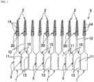
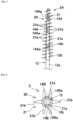
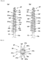
- the interdental cleaning tool 1 includes a cleaning portion 2 for interdental cleaning and a handle portion 3 as a grip, which are distinguishable in terms of function, and also includes the base portion 10 made of a synthetic resin and a soft portion 20 made of an elastomer, which are distinguishable in terms of material.
- such interdental cleaning tools 1 are manufactured in the form of an interdental cleaning tool connected body 5, which includes a plurality of interdental cleaning tools 1 separably connected in parallel to one another. A user disconnects the interdental cleaning tools 1 one by one at connecting portions 13 from one side of the interdental cleaning tool connected body 5, so as to sequentially use them.
- FIG. 1 illustrates that ten interdental cleaning tools 1 are connected in parallel to form the interdental cleaning tool connected body 5, any number of interdental cleaning tools 1 may be connected.
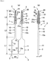
- the base portion 10 is made of a thermoplastic synthetic resin. As shown in FIGS. 1 to 6 , the base portion 10 includes: a handle base portion 11 that has a flat elongated plate shape and forms the handle portion 3; a core base portion 12 that is connected to a tip end portion of the handle base portion 11 and has an elongated shaft shape; and the connecting portions 13 separably connecting the adjacent handle base portions 11.
- the handle base portion 11 is formed in a flat elongated plate shape.
- the handle base portion 11 may have any shape other than the flat elongated plate shape as long as the shape facilitates gripping by fingers and interdental cleaning.
- the handle base portion 11 can be formed into a rod shape, a plate shape, or a continuous or stepwise curved shape, in which a cross-sectional shape is formed to be a circular shape, an oval shape (an elliptical shape, an oblong shape, a rounded rectangular shape, an egg shape, an oval shape (Japanese old coin shape), a bale shape (rectangular shape with curved short side portions, rectangular shape with rounded corners), etc.), a teardrop shape and a polygonal shape.
- the handle base portion may be provided with a curved portion or a recess for improving ease of holding.
- the tip end portion of the handle base portion 11 becomes narrower in width as approaching to the core base portion 12 side, and is smoothly connected to the core base portion 12.
- the handle base portion 11 may have any dimensions capable of facilitating the gripping by fingers and the interdental cleaning.
- the handle base portion 11 illustrated in FIGS. 1 and 2 has a length L1 of 10 mm to 25 mm, a width W1 of 4 mm to 8 mm, and a gripping-portion thickness t1 of 1.0 mm to 2.0 mm. In this manner, since the handle base portion 11 is made thin, there is less unevenness in dimension due to shrinkage of the handle base portion 11 when molding the base portion 10. In addition, occurrence of sink marks is prevented, and loading defects of the base portion 10 into second dies 40 and 41 for molding the soft portion 20 can be prevented.
- the core base portion 12 is formed in a substantially linear elongated shaft shape, and the handle base portion 11 and the core base portion 12 are disposed substantially in the identical axis line, and the core base portion 12 and the handle base portion 11 are disposed in the identical plane.
- An exposed portion 12a exposed to the outside is formed on a gripping portion side of the core base portion 12.
- a core main body 12b which is covered with an elastomer and is insertable between the teeth is formed at a tip end side portion of the core base portion 12.
- At least a portion of the core main body 12b, which is covered with the soft portion is formed in a gentle tapered shape to decrease in diameter as approaching to the tip end side.
- the portion which is not covered with the soft portion may not necessarily be linear, and for example, a shape bent continuously or stepwise may be adopted.
- a length L2 of the exposed portion 12a of the core base portion 12 from an end point of a round portion (curved portion) on a side surface of the tip end portion of the handle base portion 11, which is configured to be narrow, to a base end portion of a covering portion 21a of the soft portion 20 is set to be, for example, 10 mm to 40 mm, preferably 10 mm to 30 mm, more preferably 10 mm to 25 mm, most preferably 10 mm to 20 mm.
- a length L3 of a cleaning soft portion 21 is set to be, for example, 12 mm to 22 mm.
- a cross-sectional shape of the core base portion 12 is preferably circular, but may be a cross-sectional shape such as an oval shape, a teardrop shape or a polygonal shape.
- the tapered shape of the outer surface of the core base portion 12 makes an angle ⁇ 1 of 0.2° to 1.5° with a center line of the core base portion 12.
- the tip end portion of the core main body 12b has a diameter of 0.4 mm to 0.6 mm.
- the base end portion of the core main body 12b has a diameter of 0.8 mm to 2.0 mm.
- a curved surface end of the tip end portion of the covering portion 21a of the cleaning soft portion 21 has a diameter D of 0.5 to 1.2 mm.
- the core main body 12b is so formed that the tip end portion with a length by at least 5 mm from the tip end is reliably insertable between the teeth.
- the angle ⁇ 1 of the tapered shape of the core base portion 12 is constant over the entire length of the core base portion 12.
- the angle ⁇ 1 may also be continuously or stepwise reduced toward the tip end side of the core base portion 12.
- the exposed portion 12a may be formed in a shaft shape with a constant diameter over its entire length, and only the core main body 12b may be gently tapered to decrease in diameter as approaching to the tip end side.
- the exposed portion 12a may also be omitted, and the core main body 12b may be connected directly to the handle base portion 11.
- the present invention is applied to the I-type interdental cleaning tool 1 in which the handle base portion 11 and the core base portion 12 are disposed substantially in the identical axial line.
- the present invention can also be applied to a so-called L-shaped interdental cleaning tool 1 that includes the core base portion 12 a center line of which is inclined at an angle of, for example, 120° with respect to a center line of the handle base portion 11, and to a curve-shaped interdental cleaning tool in which a handle portion connected to a cleaning portion has a smooth curved shape of about 140° to 160°.
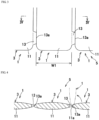
- each of the connecting portions 13 between the adjacent handle base portions 11 is integrally formed with the handle base portions 11.
- a pair of the connecting portions 13 are provided at the base end portion side and the tip end portion side of each of the handle base portions 11 with a certain spacing therebetween in the length direction.
- the connecting portions 13 are elongated in the length direction of the handle base portion 11, and are formed into a trapezoidal shape (isosceles trapezoidal shape in FIG. 3 ) in front view.
- the number of the connecting portions 13 can be arbitrarily set, and only one can be provided. However, with such a configuration, when the interdental cleaning tool 1 is manufactured, connecting strength of the adjacent base portions 10 cannot be sufficiently ensured.
- the connecting portions 13 are ruptured, the base portions 10 may be broken, and the soft portions 20 cannot be molded.
- the connecting portions 13 may be bent, and the base portions 10 cannot be loaded in an appropriate position of a second molding space 42 (see FIG. 14 ) for molding the soft portions 20, and molding defects may occur. Therefore, two or more of the connecting portions 13 are preferably provided at intervals in the length direction of the handle base portion 11.
- the connecting portions 13 are configured in the following manner.
- a cross section of the connecting portions 13 is formed in a trapezoidal shape or a triangular shape (isosceles trapezoidal shape or isosceles triangular shape in FIG. 4 ).
- bending force is concentrated on boundary portions 13a by allowing the interdental cleaning tool 1 to pivot in such a direction that the interdental cleaning tools 1 adjacent to each other overlap each other, around the boundary portions 13a.
- each circular-arc side surface 11a on a side edge of the handle base portion 11 comes into contact with the outer surfaces of the connecting portions 13. In this way, large force in a direction to pull apart the side surface 11a from the boundary portion 13a is applied by the lever principle.
- the interdental cleaning tool 1 can be completely separated at the boundary portions 13a without large deformation of the connecting portion 13.
- the shape of the connecting portions 13 can be formed arbitrarily as long as the connecting portions 13 are configured to be capable of easily and completely separating the interdental cleaning tools 1 from each other by allowing the interdental cleaning tool 1 to pivot in such a direction that the interdental cleaning tools 1 adjacent to each other overlap each other, around the connecting portions 13.
- the length direction of the fibrous materials is preferably oriented in a direction along the length direction of the base portion 10.
- This configuration makes it possible to improve the bending strength or axial buckling strength of the base portion 10 and to effectively prevent the core base portion 12 from breakage or buckling during use of the interdental cleaning tool 1.
- the fibrous materials as described above and powders such as plate-like or granular glass flakes, mica, and talc, a biting amount of a holding pin which bites into the core base portion 12 can be reduced, and a recess 14a of the formed core base portion 12 can be made shallow.
- the soft portion 20 is molded so as to be integrated with the base portion 10 using an elastomeric material, and includes the cleaning soft portion 21 externally mounted on the core base portion 12.
- the soft portion 20 it is possible to provide an insertion restriction portion having an annular shape for restricting the interdental insertion at the base end portion of the core main body 12b, or to provide a non-slip portion in which all or a part of the surface of the handle base portion 11 is covered with an elastomer.
- the insertion restriction portion and the non-slip portion are also possible to mold the insertion restriction portion and the non-slip portion independently of the cleaning soft portion 21, it is preferable to form the insertion restriction portion and the non-slip portion so as to be continuous with the base portion of the cleaning soft portion 21 since a structure of the dies becomes complicated.
- the cleaning soft portion 21 includes the covering portion 21a with which the core base portion 12 is covered, and a plurality of cleaning protrusions 21b protruding outward from the covering portion 21a at intervals in the length direction.
- the thickness of the covering portion 21a is preferably set at 0.1 mm to 0.2 mm.
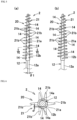
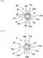
- the cleaning protrusions 21b are formed apart from one another in the length direction of the covering portion 21a, and are also arranged at intervals from one another in the circumferential direction of the covering portion 21a. More specifically, in order to make it possible to mold the cleaning protrusions 21b with the second dies 40 and 41 which will be described later, in the circumferential direction of the covering portion 21a, totally six types of the cleaning protrusions 21b are arranged at intervals from one another in the length direction of the covering portion 21a.
- the six types include: a set of the two cleaning protrusions 21b protruding from the covering portion 21a to one side in the mold opening and closing direction; a set of the two cleaning protrusions 21b protruding from the covering portion 21a to the other side in the mold opening and closing direction; one cleaning protrusion 21b protruding to one side along mating surfaces 40a and 41a from the covering portion 21a; and one cleaning protrusion 21b protruding to the other side along the mating surfaces 40a and 41a from the covering portion 21a.
- a cross-sectional area, length, number, and arrangement interval of the base end portion of the cleaning protrusions 21b can be arbitrarily set, but in view of moldability and cleaning performance, the cross-sectional area of the base end portion of the cleaning protrusion 21b is preferably set to 0.03 mm 2 to 1.5 mm 2 , more preferably 0.03 mm 2 to 1.0 mm 2 , and most preferably 0.04 mm 2 to 0.8 mm 2 .
- the length of the cleaning protrusions 21b is preferably set to 0.1 mm to 2.5 mm, more preferably 0.3 mm to 2.0 mm, and most preferably 0.5 mm to 1.7 mm.
- the number of the cleaning protrusions 21b is preferably set to 20 to 100, and the arrangement interval of the cleaning protrusion 21b is preferably set to 0.5 mm to 1.5 mm.
- conical protrusions are adopted as the cleaning protrusions 21b, protrusions having a tapered axially flat plate shape can also be adopted.
- cross-sectional shape of the cleaning protrusions 21b an arbitrary sectional shape such as an oval shape, a teardrop shape and a polygonal shape can be adopted, in addition to the circular shape.
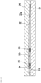
- cleaning portion recesses 14 which correspond to the holding pins penetrate the covering portion 21a and form core base portion recesses 14a in the core base portion 12 are formed.
- the cleaning portion recesses 14 are formed on a first side portion (left half of the cleaning portion 2 in FIG. 5(b) ) of the cleaning portion 2 and on a second side portion (right half of the cleaning portion 2 in FIG. 5(b) ). Two or more of the cleaning portion recesses 14 are formed at intervals in the axial direction of the cleaning portion 2.
- At least one set of two cleaning portion recesses 14 out of plural pairs of the cleaning portion recesses 14 which form a pair of the first side portion and the second side portion, are formed at an interval in the axial direction of the cleaning portion 2 so as not to overlap each other in the circumferential direction of the cleaning portion 2.
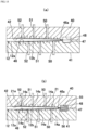
- the core base portion recesses 14a are formed such that the base portion 10 with relatively high temperature immediately after being molded by first dies 30 and 31 is softened by exposure to heat of the elastomer filled in the second dies 40 and 41, and that tip end portions of the holding pins abut against the softened core base portion 12.
- first side portion and second side portion of the cleaning portion 2 refer to a portion of the cleaning portion 2, which is molded with the second die 40, and a portion of the cleaning portion 2, which is formed by the second die 41.
- the first side portion and the second side portion mean a front side half portion and back side half portion of the cleaning portion 2, which correspond to the front side and back side of the handle base portion 11 having a flat shape.
- the cleaning portion recesses 14 which form a pair of the first side portion and the second side portion mean cleaning portion recesses 14 located at the same order positions counted from the tip end of the cleaning portion 2 in the first side portion and the second side portion.
- a maximum depth d of each of the core base portion recesses 14a from an outer peripheral surface of the core base portion 12 can be arbitrarily set.
- the maximum depth d is desirably set to 0.01 mm or more and 0.085 mm or less, and preferably 0.01 mm or more and 0.065 mm or less, in order to prevent the breakage of the core base portion 12 due to an occurrence of a concentration of a large stress at the forming position of the core base portion recess 14a when bending force is applied to the cleaning portion 2 at the time of inserting the cleaning portion 2 into the interdental space or during interdental cleaning by the cleaning portion 2.
- a maximum cross-sectional area of the core base portion 12 at the position corresponding to the core base portion recess 14a is set to 55.0 to 99.6%, preferably 70.0 to 99.0%, more preferably 80.0 to 97.9%, most preferably 90.0 to 97.9%.
- the occurrence of the stress concentration on the core base portion recess 14a is reduced, and the breakage of the core base portion 12 at the time of inserting into the interdental space or during the interdental cleaning can be prevented more effectively.
- a front of the cleaning portion recess 14 is formed in the same shape as a pin tip shape of the holding pin, and is formed into a shape elongated in a spiral direction of the cleaning portion shaft, such as a parallelogram shape, a polygonal shape such as a square or rectangular shape, a circular shape, an oval shape, a teardrop shape and the like. All of the plurality of cleaning portion recesses 14 provided in the interdental cleaning tool 1 may be formed in the same shape, or those in different shapes according to distances from the tip end portion of the cleaning portion 2 can also be arbitrarily combined and mixed with one another.
- the cleaning portion recess 14 can be configured as follows.
- other configurations can be configured similarly to the interdental cleaning tool 1.
- cleaning portion recesses 14F having a front shape that is elongated in the axial direction of the cleaning portion 2F, specifically, a bale shape (having a rectangular shape with curved short side portions, rectangular shape with rounded corners), are formed.
- the pin tip shape of the holding pin is formed into a bale shape (rectangular shape with curved short side portions, rectangular shape with rounded corners), whereby the cleaning portion recess 14F is formed between cleaning protrusions 21b adjacent to one another in the circumferential direction so that a length direction of the cleaning portion recesses 14F can coincide with the axial direction of the cleaning portion 2.
- bale shape rectangular shape with curved short side portions, rectangular shape with rounded corners
- a rectangular shape as in a cleaning portion recess 14A of a cleaning portion 2A shown in FIG. 7
- an elliptical shape or other shapes.
- all of the plurality of cleaning portion recesses 14 provided in the interdental cleaning tool 1 can be formed in the same shape as in this embodiment, or those in different shapes according to distances from the tip end portion of the cleaning portion 2 can also be arbitrarily combined and mixed with one another.
- each of the cleaning portion recesses 14 is configured to have an elongated shape in the axial direction, a width of the cleaning portion recess 14 (the width along the circumferential direction of the cleaning portion) is small as compared to a circular cleaning portion recess formed by a circular holding pin having the same cross-sectional area as the cleaning portion recesses 14F and 14A.
- the concentration of the stress in the vicinity of the cleaning portion recess when the same force is applied is alleviated, so that the effect of preventing the breakage of the core base portion is obtained.
- the pin tip shape of the holding pin having an elongated shape in the axial direction has a longer length in the cleaning axis direction than the circular holding pin having the same cross-sectional area.
- the holding pin having an elongated shape in the axial direction has stronger holding force for the core base portion 12 than the circular holding pin, and accordingly, vibrations of the core base portion during the molding of the soft portion are suppressed, and a depth of each of core base portion recesses 14Aa becomes difficult to deepen. In this way, the stress generated at the position where the core base portion recess 14Aa is provided can be alleviated, and the effect of preventing the breakage of the core base portion is obtained.
- a cleaning portion recess 14G having a long front shape can also be formed at an angle in an axial direction of the cleaning portion 2G (in a spiral direction of the cleaning portion shaft).
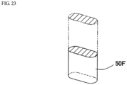
- the cleaning portion recess 14G can be formed by a holding pin 50G having a plate-shape as shown in FIG. 22 .
- an opening area of each of the core base portion recesses is desirably set to 0.15 mm 2 to 0.60 mm 2 , preferably 0.17 mm 2 to 0.50 mm 2 , more preferably 0.20 mm 2 to 0.40 mm 2 , in order to prevent the breakage of the core base portion due to the occurrence of the concentration of the large stress at the forming position of the core base portion recess when the bending force is applied to the cleaning portion at the time of inserting the cleaning portion into the interdental space or during the interdental cleaning by the cleaning portion.
- the core base portion recess which is long in the axial direction is set to preferably 0.4 mm to 1.5 mm in maximum in the axial direction, more preferably 0.4 to 1.3 mm, more preferably 0.5 mm or more to 1.1 mm or less, most preferably 0.6 mm to 1.0 mm or less.
- the opening area of the core base portion recess is set to preferably 0.15 mm 2 to 0.6 mm 2 , more preferably 0.17 mm 2 to 0.5 mm 2 , and most preferably to 0.2 mm 2 to 0.4 mm 2 .
- a total area of the core base portion recesses formed in one interdental cleaning tool 1 be set to 0.90 mm 2 to 3.6 mm 2 .
- the opening areas of all the core base portion recesses can be set to the same size, but it is preferable to set the opening areas so that the core base portion recess closer to the tip end side of the core base portion 12 has a smaller opening area.
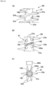
- a bottom surface of the core base portion recess 14a of the cleaning portion recess 14 reflects a shape of tip end supporting surfaces of the holding pins 50 to 52 which are described later.
- the bottom surface is constituted by a flat surface in a direction perpendicular to the depth direction of the core base portion recess 14a.
- the bottom surface may be configured in a recessed shape having a central part that rises as compared with both side portions as viewed from the axial direction of the cleaning portion 2. For example, in a state in which the holding pin bites into the entire surface of the tip end supporting surface and abuts against the same like a core base portion recess 14Ca of a cleaning portion recess 14C shown in FIG.
- the bottom surface can be formed into an inverted V-shaped mount shape in which the shape of the tip end supporting surface is directly transferred and the center is raised, so that a maximum depth of the recess 14Ca is set so as not to be at the central part of the recess 14Ca but to be at side positions sandwiching the central part, i.e., at the side end positions in this embodiment.
- the bottom surface may have a shape that gently rises from both ends to the central part, and may have various other shapes, by changing the shape of the tip end supporting surface of the holding pin, for example, as shown in a core base portion recess 14Ba of a cleaning portion recess 14B in FIG. 8 .
- each of the core base portion recesses 14Ba and 14Ca is separated and formed into two parts with the central part interposed therebetween.
- an opening area of the core base portion recess 14a can be arbitrarily set, the opening area is set to preferably 0.08 mm 2 to 0.35 mm 2 , more preferably 0.09 mm 2 to 0.30 mm 2 , and most preferably 0.1 mm 2 to 0.25 mm 2 .
- a total area of the core base portion recesses 14a formed in one interdental cleaning tool 1 is set to preferably 0.048 mm 2 to 2.1 mm 2 , more preferably 0.54 mm 2 to 1.8 mm 2 , further preferably 0.60 mm 2 to 1.5 mm 2 , most preferably 0.9 mm 2 to 1.3 mm 2 .
- the opening areas of all the core base portion recesses 14a can be set to substantially the same size, but it is preferable to set the opening area so that the core base portion recess 14a on the tip end side of the core base portion 12 has a smaller opening area.
- the opening area of the core base portion recess 14a means an area surrounded by a projected figure of a boundary line between the core base portion 12 exposed in the core base portion recess 14a, and the cleaning soft portion 21.
- the opening area is defined with respect to a plane perpendicular to the depth direction center line DL (see FIG. 19 ) of the core base portion recess 14a.
- all the cleaning portion recesses 14 which are paired with the first side portion and the second side portion can be formed at intervals in the axial direction of the cleaning portion 2 so as not to overlap one another in the circumferential direction of the cleaning portion 2.
- only specific cleaning portion recesses 14 which are paired with the first side portion and the second side portion can be formed at intervals in the axial direction of the cleaning portion 2 so as not to overlap one another in the circumferential direction of the cleaning portion 2, and the remaining cleaning portion recesses 14 can be provided so as to face each other with the core base portion 12 interposed therebetween or to be deviated in the axial direction of the cleaning portion 2 within the range equal to or less than the diameter of the cleaning portion recess 14.
- the cleaning portion recesses 14 of the first side portion can be provided substantially at the central part of the arrangement interval of the cleaning portion recesses 14 of the second side portion in the axial direction.
- the cleaning portion recesses 14 of the first side portion can also be provided at positions biased toward the tip end side or base end side of the arrangement interval of the cleaning portion recesses 14 of the second side portion in axial direction.
- the cleaning portion recesses 14 of the first side portion are formed at least at a position of 1.0 to 2.5 mm, a position of 5.5 to 7.0 mm, and a position of 10.0 to 11.5 mm from the tip end portion of the cleaning portion 2, for example.
- the cleaning portion recesses 14 of the second side portion are formed at a position of 1.4 to 3.7 mm, a position of 5.9 to 8.2 mm, and a position of 10.4 to 12.7 mm from the tip end portion of the cleaning portion 2, for example.
- At least the cleaning portion recesses 14 adjacent to the region be arranged to be shifted in the axial direction of the cleaning portion 2 so that the cleaning portion recesses 14 are not disposed in the region.
- the number of sets of the cleaning portion recesses 14 be two or more, desirably three or more. In this way, the number of sets of the cleaning portion recesses 14 is set to three or more or four or more, whereby the stress generated by the bending force acting on the cleaning portion 2 at the time of the interdental insertion or during the interdental cleaning can be dispersed.
- the depth of the core base portion recesses 14a is made shallow while ensuring holding properties for the core base portion 12 by the holding pins 50 to 52, whereby the breakage of the core base portion 12 due to local concentration of a large stress can be effectively prevented during the interdental cleaning.
- the number of the cleaning portion recesses 14 of the first side portion and the number of the cleaning portion recesses 14 of the second side portion are preferably the same, but can be differentiated from each other.
- the number of the cleaning portion recesses 14 of the first side portion can be reduced by one than the number of the cleaning portion recesses 14 of the second side portion.
- the arrangement interval of the cleaning portion recesses 14 of the first side portion and the second side portion in the axial direction of the cleaning portion 2 can be set to be substantially uniform or narrowed as approaching to the tip end side of the cleaning portion 2.
- the tip end portion of the cleaning portion 2 is a substantially linear and elongated shaft-shaped structure configured to have a smaller diameter than the base end portion, and is liable to structurally change with respect to the force applied by the molding when the cleaning soft portion 21 is molded. Therefore, as mentioned above, if the arrangement interval of the cleaning portion recesses 14 is set so as to become narrower as approaching to the tip end side of the cleaning portion 2 or is set to be substantially uniform, it is easy to suppress the core base portion 12 from moving from a predetermined position during molding of the soft portion 20. In particular, it is more preferable to set the arrangement interval to be substantially uniform since external force applied to the core base portion 12 at the time of molding the soft portion 20 is likely to be uniform.
- the core base portion recesses 14a are formed alternately on the first side portion and second side portion of the core base portion 12 at intervals in the axial direction of the core base portion 12. In this way, the pair of core base portion recesses can be prevented from being formed at the same position in the axial direction of the core base portion 12. Therefore, the cross-sectional area of the core base portion 12 at each of the positions corresponding to the core base portion recesses 14a can be increased to prevent the core base portion 12 from being broken.
- the positions in the axial direction of the core base portion, where the respective holding pins apply force to the core base portion do not overlap each other, a portion in the axial direction of the core base portion, where the core base portion receives the force is longer than in the case of disposing the holding pins which overlap each other in the circumferential direction.
- the core base portion is more strongly held, and the core base portion recesses 14Ea formed during the molding of the soft portion 20 is suppressed from being deepened.
- the cross-sectional area of the core base portion 12 at each of the positions corresponding to the core base portion recesses 14Ea is increased, and the occurrence of breakage of the core base portion 12 can be prevented.
- Arrangement positions of the cleaning portion recesses 14 with respect to the cleaning portion 2 can also be configured as follows.
- cleaning portion recesses 14D and 14E, and core base portion recesses 14Da and 14Ea are formed by changing only forming positions thereof with respect to the cleaning portion 2 from the cleaning portion recesses 14 and the core base portion recesses 14a, and the front shape, depth, and opening area of each of the core base portion recesses can be configured similarly to the cleaning portion recesses 14 and the core base portion recesses 14a.
- the cleaning portion recesses 14D can also be formed so that a center line of the cleaning portion recess 14D of the first side portion and the center line of the cleaning portion recess 14D of the second side portion are arranged in parallel so as to be shifted by a predetermined distance in a radial direction of the cleaning portion 2D.
- the cleaning portion recess 14E and core base portion recess 14Ea of the first side portion and the cleaning portion recess 14E and core base portion recess 14Ea of the second side portion can also be arranged so as to face each other with a core base portion 12E interposed therebetween, and to allow the depth direction (DL in FIG. 19 ) of the cleaning portion recess to be inclined at an angle ⁇ 2 in the circumferential direction with respect to the mold opening and closing direction of the second dies 40 and 41 (see FIG. 14 ).
- the cleaning portion recesses 14E In the cleaning portion 2E shown in FIG. 11 , only a second set of the cleaning portion recesses 14 from the tip end of the cleaning portion 2 shown in FIG. 5 is replaced by the cleaning portion recesses 14E, and first and third sets from the tip end of the cleaning portion 2E are constituted by the cleaning portion recesses 14 arranged so that the depth direction of the cleaning portion recesses coincides with the mold opening and closing direction of the second dies 40 and 41.
- one or plural sets of the cleaning portion recesses 14 at an arbitrary position in the cleaning portion 2 can also be replaced by the cleaning portion recesses 14E.
- the angle ⁇ 2 exceeds 60°, holding pins 62 (see FIG. 17 ) provided in adjacent cleaning soft portion molding portions 46 sometimes interfere with each other, so that the angle ⁇ 2 is preferably set to 60° or less, desirably 45° or less.
- the cleaning portion recess can also be formed by giving the angle ⁇ 2 to an opposite side across a segment in the mold opening and closing direction, which passes through the center of the cleaning portion 2, or alternatively, plural types of the cleaning portion recesses with different angles ⁇ 2 can also be provided for the cleaning portion.
- the cleaning portion recesses 14E are provided at positions where the angle ⁇ 2 is provided with respect to the mold opening and closing direction, in the case of forming the plurality of cleaning protrusions 21b, which protrude outward, in the cleaning soft portion 21, a degree of freedom in arrangement layout of the cleaning protrusions 21b can be improved.
- the cleaning portion recesses 14E are formed by holding pins which hold the core base portion 12 in the central part of the second molding space 42.
- the positions of the holding pins 62 can be adjusted in the length direction and the circumferential direction with respect to the second molding space 42 without interfering with the forming positions of the cleaning protrusions 21b, the degree of freedom in the arrangement layout of the cleaning protrusions 21b can be improved.
- the handle base portion 11 is formed flat, when the space between the molars is cleaned with the handle base portion 11 being grepped with the fingers, the cleaning portion 2 is curved as shown by a virtual line in FIG. 2 within a plane substantially perpendicular to the plane including the handle base portion 11 (that is, in the mold opening and closing direction). Since the cleaning portion recesses 14E are disposed so that the depth direction thereof forms an angle ⁇ 2 with respect to the mold opening and closing direction, the core base portion 12E can be effectively prevented from being broken from the cleaning portion recess 14E as a starting point.
- the method for manufacturing the interdental cleaning tool includes: a base portion molding step of filling a synthetic resin material into first molding spaces 32 of the first dies 30 and 31 to form the base portions 10; and a soft portion molding step of placing, in the second molding spaces 42 of the second dies 40 and 41, the base portions 10 molded in the first dies 30 and 31 and then filling an elastomeric material into the second molding spaces 42 to form the soft portions 20.
- the first dies 30 and 31 correspond to a first mold and second mold of the first die, respectively
- the second dies 40 and 41 correspond to a first mold and second mold of the second die, respectively.
- the first dies 30 and 31 used have: a plurality of the first molding spaces 32 that are arranged in parallel, and each have a core base portion molding portion 32a and a handle base portion molding portion 32b; a pair of connecting portion molding portions 35 each formed between the adjacent handle base portion molding portions 32b to communicate therewith; a runner 33 formed on the base end side of the plurality of first molding spaces 32; and gates 34 through which the first molding spaces 32 communicate with the runner 33.
- a synthetic resin material is allowed to pass through the gates 34 and filled into the first molding spaces 32 to allow a plurality of the base portions 10 to be simultaneously molded.
- a primary molded product 10A is formed, which includes the plurality of base portions 10, a runner portion 37, gate portions 36, and the connecting portions 13.
- the base portions 10 may be molded one by one.
- the simultaneous molding of a plurality of base portions 10 makes it possible to improve the productivity and to transfer the base portions 10 at the same time by holding the molded runner portion 37, which can improve the workability and thus is preferred.
- Each gate 34 may be formed at any position on the base end portion side opposite to the core base portion molding portion 32a of the first molding space 32, more preferably on the base end portion side opposite to the core base portion molding portion 32a of the first molding space 32 with respect to the connecting portion molding portion 35.
- a side gate should preferably be formed as the gate 34 at the base end portion of the first molding space 32, so that a possibility of causing the gate portions 36 of the primary molded product 10A to be pinched between the second dies 40 and 41 can be reduced in the process of loading the primary molded product 10A into the second dies 40 and 41.
- a hot runner may be provided instead of the runner 33 including a cold runner in the first dies 30 and 31.
- the use of the hot runner can make the first dies 30 and 31 large and increase manufacturing cost. Therefore, the runner 33 including the cold runner is preferably provided.
- the plurality of base portions 10 can be stably connected to one another by the runner portion 37, which can improve the handling properties of the primary molded product 10A in the process of transferring the primary molded product 10A into the second dies 40 and 41, and thus is preferred.
- a pin gate having, for example, a cylindrical or spindle shape with a diameter of 0.1 to 1.5 mm can be preferably adopted as each gate 34 to allow use of a cold runner, and the gates 34 can be arranged at narrow intervals, which can make the molded product small.
- the primary molded product 10A molded in the first dies 30 and 31 is placed in each of the second molding spaces 42 of the second dies 40 and 41. Then, the second molding space 42 is filled with an elastomeric material to mold the soft portion 20, whereby the interdental cleaning tool connected body 5 in which a plurality of the interdental cleaning tools 1 are continuously connected in parallel to one another is obtained.
- the second dies 40 and 41 used in the soft portion molding step will be described.
- the second dies 40 and 41 have a plurality of the second molding spaces 42, which are formed at positions corresponding to a plurality of the base portions 10 of the primary molded product 10A molded in the first dies 30 and 31.
- the second dies 40 and 41 also have fitting spaces 43, 44 and 45 formed to accommodate the runner portion 37, a plurality of the gate portions 36, and the connecting portions 13 in the primary molded product 10A.
- the cleaning soft portion molding portion 46 surrounding the core base portion 12 is formed as the second molding space 42.
- Gates 47 which open to the tip end portions of the cleaning soft portion molding portions 46 are formed on the mating surfaces 40a and 41a of the second dies 40 and 41 on the tip end side of the cleaning soft portion molding portions 46.
- the plurality of gates 47 communicate with a common runner 48 formed in the second dies 40 and 41.
- the elastomeric material is supplied from the common runner 48 to the plurality of second molding spaces 42 via the plurality of gates 47.
- the gates 47 are preferably set to be a diameter of 0.1 mm or more and 1.0 mm or less.
- the tip end side holding pin 50, the intermediate portion holding pin 51 and the base end side holding pin 52 are provided so as to respectively correspond to a tip end side portion, intermediate portion and base end side portion of the cleaning soft portion molding portion 46.
- the holding pin of the second die 41 paired with the holding pin of the second die 40 means a holding pin in the same order counted from the tip end of the cleaning soft portion molding portion 46.
- a specific holding pin of the second die 40 and a specific holding pin of the second die 41 paired therewith can also be installed in the respective second dies (40, 41) at an interval in the axial direction of the cleaning soft portion molding portion 46 so as not to overlap each other in the circumferential direction of the cleaning soft portion molding portion 46.
- a large bending force tends to act on a position located by 6 mm apart from the tip end portion of the cleaning portion 2, during cleaning the space between the molars. Therefore, it is preferable that only the second holding pins 51 holding the vicinity of the position be disposed so as to be shifted in the axial direction of the cleaning soft portion molding portion 46.
- the remaining pairs of holding pins are provided opposite to each other with the core base portion 12 interposed therebetween, or are disposed so as to be shifted in the axial direction of the core base portion 12 within a range equal to or less than the diameter of the holding pins.
- the three pairs of holding pins 50 to 52 of the second dies 40 and 41 are freely movably provided in a direction substantially perpendicular to the mating surfaces 40a and 41a of the second dies 40 and 41, that is, in the mold opening and closing direction of the second dies 40 and 41.
- the core base portion 12 of the base portion 10 has the tip end portions of these three pairs of holding pins 50 to 52 protruding into the cleaning soft portion molding portion 46, and the core base portion 12 is sandwiched between the tip end portions of each of the holding pins 50 to 52. In this way, the core base portion 12 is accurately positioned and held in the central part of the cleaning soft portion molding portion 46.
- the holding pins may be fixed to the dies in advance in a state of protruding into the cleaning soft portion molding portion of the second die.
- a cross-sectional area of the tip end portion of each of the holding pins 50 to 52 is substantially identical in size to one another, or a cross-sectional area of the holding pins 50 located at the most tip end side is smaller than the cross-sectional areas of the tip end portions of the holding pins at other positions.
- the intermediate portion holding pins 51 and the base end side holding pins 52 are configured to be substantially identical in size to one another, or configured so that the intermediate portion holding pins 51 are larger than the base end side holding pins 52. That is, a passage area at the tip end side portion of the cleaning soft portion molding portion 46 is small.
- the cross-sectional area of the tip end side holding pins 50 is made as small as possible, whereby a flow resistance of the elastomeric material is set as small as possible.
- the influence of the Karman vortex generated during molding is suppressed, whereby poor filling of the elastomeric material with respect to the cleaning soft portion molding portion 46 can be prevented, and excessive melting of the core base portion 12 can be prevented.
- such a small cross-sectional area of the tip end side holding pins 50 is preferable.
- the holding pins 50 to 52 of the second die 41 are configured as follows.
- the holding pins 50 to 52 of the second die 40 are configured similarly to the holding pins 50 to 52 of the second die 41 except for being disposed so as to be shifted to the base end portion side with respect to the holding pins 50 to 52 of the second die 41, and accordingly, only the holding pins 50 to 52 of the second die 41 will be described.
- the tip end side holding pin 50 of the second die 41 is provided within a range of 3 mm from a tip end portion 46a of the cleaning soft portion molding portion 46 toward the base end side, and the cross-sectional area thereof is set to 0.03 mm 2 to 0.3 mm 2 .
- the intermediate portion holding pin 51 is provided within a range of ⁇ 10% of the length of the cleaning portion 2 in the axial direction around an intermediate point between the tip end side holding pin 50 and the base end side holding pin 52, and the cross-sectional area thereof is set to 0.12 mm 2 to 1.2 mm 2 .
- the base end side holding pin 52 is provided within a range of 6 mm from the base end portion of the cleaning soft portion molding portion 46 toward the tip end side, and the cross-sectional area thereof is set to 0.1 mm 2 to 1.1 mm 2 .
- the cross-sectional areas are set to these values, whereby it can be expected not only to ensure the fixation of the core base portion 12 during molding but also to prevent the influence on the molded product due to the Karman vortex generated during molding.
- the core base portion 12 is softened by heat of the elastomeric material, and the tip end portions of the holding pins 50 to 52 cause the core base portion recesses 14a to be formed alternately on the first side portion and second side portion of the core base portion 12 at intervals in the axial direction of the core base portion 12.
- a pair of the core base portion recesses can be prevented from being formed at the same position in the axial direction of the core base portion 12. Therefore, the cross-sectional area of the core base portion 12 at each of the positions corresponding to the core base portion recesses 14a can be increased to prevent the core base portion 12 from being broken.
- a portion in the axial direction of the core base portion, where the core base portion is subjected to the force is longer than that in the arrangement of the holding pins which overlap each other in the circumferential direction.
- the core base portion is more firmly held, and the core base portion recesses 14Ea formed during the molding of the soft portion 20 is suppressed from being deepened.
- the cross-sectional area of the core base portion 12 at each of the positions corresponding to the core base portion recesses 14Ea is increased, and the occurrence of breakage of the core base portion 12 can be prevented.
- the cross-sectional area of the holding pin 50 is set smaller than the cross-sectional areas of the holding pins 51 and 52.
- the holding pins 50 to 52 are fixed to the dies in advance in a state in which the holding pins 50 to 52 are protruded into the cleaning soft portion molding portion of the second dies, and it is also possible to adopt a manufacturing method in which the core base portion is held when the second dies 40 and 41 are closed.
- the runner portion 37 and the gate portions 36 which contain the synthetic resin, are removed.
- a runner portion 55 and gate portions 56 which contain the elastomer molded by the runner 48 and the gates 47, are removed. In this way, the interdental cleaning tools 1 are obtained.
- the cross-sectional shape of the tip end portion of each of the holding pins 50 to 52 is formed circular in the present embodiment.
- the cross-sectional shape may be formed in, for example, an oval shape, a teardrop shape, a rectangular shape, a bale shape (rectangular shape with curved short side portions, rectangular shape with rounded corners) elongated in the length direction of the cleaning soft portion molding portion 46.
- holding pins having different cross-sectional shapes may be arbitrarily combined and used.
- holding pins 50F are provided, each of which has a cross-sectional shape elongated in the length direction of the second molding space 42, i.e., a bale shape (rectangular shape with curved short side portions, rectangular shape with rounded corners) in this embodiment, instead of the holding pins 50 to 52, as shown in FIG. 23 .
- a length dimension of each of the holding pins along the length direction of the second molding space is set to 0.4 mm or more and 1.5 mm or less, more preferably 0.5 mm to 1.0 mm, and a cross-sectional area thereof (sectional area of a cross section perpendicular to the axial direction of the tip end portion) is set to 0.2 mm 2 or more and 0.6 2 mm or less.
- the pins are formed into a shape elongated in the length direction of the second molding space 42, whereby the influence of the Karman vortex during the molding can be suppressed.
- bale shape rectangular shape with curved short side portions, rectangular shape with rounded corners
- various shapes such as an elliptical shape, a rectangular shape, and a teardrop shape are possible.
- holding pins 50G having a rectangular plate-shaped cross section are provided at an angle with respect to the length direction of the second molding space 42 as shown in FIG. 22C , instead of the holding pins 50 to 52.
- Tip end surfaces of the holding pins 50 to 52 which abut against the core base portion 12, are constituted by flat surfaces perpendicular to the axial direction of the holding pins 50 to 52, as shown in FIG. 18(a) .
- the tip end surfaces may be constituted by circular arc surfaces along the outer peripheral surface of the core base portion 12, as in holding pins 60 shown in FIG. 18(b) , or may be each constituted by a pair of inclined planes connected in an isosceles triangle as in holding pins 61 shown in FIG. 18(c) .
- the core base portion 12 can be accurately held in the central part of the second molding space 42, and moreover, the holding properties for the core base portion 12 can be improved. Accordingly, this configuration is preferable. Moreover, holding pins having tip end surfaces with different shapes may be arbitrarily combined and used.
- a tip end supporting surface 7 abutting against the core base portion 12 of each of the holding pins 61 is formed such that a central part 70 is recessed as compared with both side parts 71 and 71 when viewed from the axial direction of the cleaning soft portion molding portion 46, as shown in FIG. 24 .
- the tip end supporting surface 7 is formed into a shape having regions which abut against at least both side parts 71 from the beginning when the holding pin 61 contacts the outer surface of the core base portion 12.
- the core base portion 12 is held in a stable posture by force dispersed from the beginning of the contact of the holding pin by the at least both side parts 71. Therefore, the holding pin 61 can hold the core base portion 12 without deeply biting into the core base portion 12, and the depth of the core base portion recess 14a to be formed can be made shallow.
- both side parts 71 are first brought into contact with the outer surface of the core base portion 12, and hold the core base portion 12 in a stable posture at at least two positions as compared with the conventional flat pin.
- the holding pin 61 usually bites into the core base portion 12, due to the core base portion 12 being not completely cooled down and being in a soft state, or due to own weight thereof or the like.
- the holding pin 61 supports the core base portion 12 at at least two positions from the beginning, and therefore, force thereof is dispersed. Instead of biting deeply from the beginning like the conventional flat pin, the holding pin 61 receives the force on the entire tip end supporting surface 7, and such a biting depth is suppressed.
- the core base portion 12 is thermally expanded or softened by being exposed to high temperature elastomer, and furthermore, the core base portion 12 receives force and vibrates during the filling with the elastomer, and the holding pin 61 attempts to further bite into the core base portion 12.
- the core base portion 12 is held in a stable posture at two positions from the beginning, and the above-described vibrations can also be effectively suppressed. Therefore, final biting is also suppressed to be shallow.
- the shape of the tip end supporting surface 7 of the holding pin 61 is formed into a shape recessed substantially in a V shape when viewed from the axial direction of the cleaning soft portion molding portion 46.
- the present invention is not limited to this.
- the shape of the tip end supporting surface 7 may be one having a gentle shape that is substantially U- shaped when viewed from the axial direction of the cleaning soft portion molding portion 46 as shown in FIG. 25(a) , and may be a shape in which protrusions 72 are provided on both side portions when viewed from the axial direction of the cleaning soft portion molding portion 46 as shown in FIG. 25(b) , for example.
- Both side parts 71 which abut against the core base portion 12 from the beginning, do not necessarily have to include the exemplified side end edges of the tip end supporting surface 7, but may be intermediate regions between the central part 70 and the side end edges.
- the tip end supporting surface 7 such a shape is adopted, in which the central part 70 initially maintains a gap with the outer surface of the core base portion 12 without abutting against the outer surface.
- the tip end supporting surface 7 just needs to have a shape in which at least both side parts 71 sandwiching the central part 70 abut against the outer surface from the beginning. Such a shape in which the central part 70 also abuts simultaneously is also included in the present invention.
- FIG. 25(c) a shape shown in FIG. 25(c) , which is substantially U-shaped as in FIG. 25(a) and has the entire surface of the tip end supporting surface 7 abutting against the core base portion 12 from the beginning, is also included in the present invention.
- the arrangement positions of the holding pins 50 to 52 with respect to the second dies 40 and 41 can also be configured as follows.
- the holding pin 62 of the second die 40 and the holding pin 62 of the second die 41 can also be disposed in such a manner of being opposite to each other with the core base portion 12 interposed therebetween, and that the axial direction thereof forms the angle ⁇ 2 in the circumferential direction with respect to the mold opening and closing direction of the second dies 40 and 41.
- the holding pins 62 can be replaced by the holding pins 62.
- the first and third sets from the tip end of the cleaning soft portion molding portion 46 can be constituted by the holding pins arranged so that the axial direction thereof coincides with the mold opening and closing direction of the second dies 40 and 41.
- one or plural sets of the holding pins at arbitrary positions in the cleaning soft portion molding portion 46 can be replaced by the holding pins 62.
- the holding pins 62 provided in the adjacent cleaning soft portion molding portions 46 sometimes interfere with each other, so that the angle ⁇ 2 is set preferably to 60° or less, desirably 45° or less.
- Plural types of the holding pins 62 having different angles ⁇ 2 can also be provided in the second dies 40 and 41.
- the holding pins 62 may be provided at the positions where the angle ⁇ 2 is provided with respect to the mold opening and closing direction. Under such a condition, when the plurality of cleaning protrusions 21b which protrude outward are formed in the cleaning soft portion 21, the degree of freedom in arrangement layout of the cleaning protrusions 21b can be improved. In other words, the holding pins 62 holds the core base portion 12 in the central part of the cleaning soft portion molding portion 46.
- the handle base portion 11 is formed flat.
- the cleaning portion 2 is curved within the plane substantially perpendicular to the plane including the handle base portion 11 (that is, in the mold opening and closing direction).
- the core base portion 12 can be effectively prevented from being broken from the core base portion recess 14Ea, which is formed by each of the holding pins 62, as a starting point during use.
- a rod-shaped core base portion having a diameter of 0.65 mm and a length of 10 mm was used, in which core base portion recesses with a predetermined depth were formed in a first side portion and a second side portion.
- tests were carried out while placing the first side portion at a lower position. Accordingly, a "lower surface” coincides with the first side portion, and an “upper surface” coincides with the second side portion.
- the "planar shape of the recess” means a shape obtained when the core base portion recess is observed from above.
- the “diameter or width of the recess” means a diameter when a planar shape of the core base portion recess is circular, and when the planar shape is other than being circular, means a maximum length among lengths between intersections of planes (VS in FIG. 19 ) perpendicular to a central axis (CL in FIG. 19 ) of the core base portion and the end portions of the core base portion recess.
- the “length of the recess” means a maximum length among lengths (UL in FIG. 19 ) between intersections (T, B in FIG. 19 ) of the plane (BS in FIG. 19 ) including the central axis (CL in FIG. 19 ) of the core base portion and the end portions of the core base portion recess.
- the "depth of recess” means a "maximum depth of the core base portion recess”.
- Example 1 on the first side portion of the core base portion, a core base portion recess having a circular shape with a diameter of 0.4 mm and a depth of 0.07 mm was formed with a center thereof positioned at a position of 6.0 mm from a tip end portion of the core base portion.
- a core base portion recess having a circular shape with a diameter of 0.4 mm and a depth of 0.07 mm was formed with a center positioned at a position of 6.8 mm from the tip end portion of the core base portion. That is, an interval between the core base portion recesses of the first side portion and the second side portion in the axial direction (UL direction in FIG.
- the “interval between the core base portion recesses of the first side portion and the second side portion in the axial direction of the core base portion" is obtained by the following procedure. First, a plane (BS in FIG. 19 ) including UL and a center line (CL in FIG. 19 ) of the core base portion is set. Next, perpendicular lines are drawn to CL from the intersections (B, T in FIG. 19 ) of the respective core base portion recesses of the first side portion and the second side portion and the BS, and intersections of the perpendicular lines and CL are obtained.
- the obtained minimum length is defined as the "interval between the core base portion recesses of the first side portion and the second side portion in the axial direction of the core base portion".
- Example 2 was configured similarly to Example 1 except that the first side portion in which the core base portion recess was formed with the center positioned at a position of 6.0 mm from the tip end portion of the core base portion was placed on the lower surface, and that the interval between the core base portion recesses of the first side portion and the second side portion in the axial direction of the core base portion was set to three times the maximum axial length of the core base portion recess.
- Example 3 was configured similarly to Example 1 except that, as each of the core base portion recesses, a bale shape (rectangular shape with curved short side portions, rectangular shape with rounded corners), in which both end portions were formed into semicircles with a diameter of 0.4 mm and a length of the recess was set to 1.14 mm, was formed.
- a bale shape rectangular shape with curved short side portions, rectangular shape with rounded corners
- Example 4 was configured similarly to Example 2 except that, as each of the core base portion recesses, a bale shape (rectangular shape with curved short side portions, rectangular shape with rounded corners), in which both end portions were formed into semicircles with a diameter of 0.4 mm and a length of the recess was set to 1.14 mm, was formed.
- a bale shape rectangular shape with curved short side portions, rectangular shape with rounded corners
- Example 5 was configured similarly to Example 1 except that, as each of the core base portion recesses, a core base portion recess having a rectangular shape, in which a width of the recess was set to 0.4 mm and a length of the recess was set to 1.2 mm.
- Example 6 was configured similarly to Example 2 except that, as each of the core base portion recesses, a core base portion recess having a rectangular shape, in which a width of the recess was set to 0.4 mm and a length of the recess was set to 1.2 mm, was formed.
- Example 7 was configured similarly to Example 3 except that the interval between the core base portion recesses of the first side portion and the second side portion in the axial direction of the core base portion was set to 1 time the maximum axial length of the core base recess.
- Example 8 was configured similarly to Example 3 except that the interval between the core base portion recesses of the first side portion and the second side portion in the axial direction of the core base portion was set to one fourth times the maximum axial length of the core base recess.
- Example 9 was configured similarly to Example 5 except that the interval between the core base portion recesses of the first side portion and the second side portion in the axial direction of the core base portion was set to 1 time the maximum axial length of the core base recess.
- Example 10 was configured similarly to Example 1 except that the interval between the core base portion recesses of the first side portion and the second side portion in the axial direction of the core base portion was set to 1 time the maximum axial length of the core base recess, and that the depth of the recess was set to 0.02 mm.
- Example 11 was configured similarly to Example 10 except that the depth of the recess was set to 0.05 mm.
- Example 12 was configured similarly to Example 8 except that the depth of the recess was set to 0.02 mm.
- Example 13 was configured similarly to Example 12 except that the interval between the core base portion recesses of the first side portion and the second side portion in the axial direction of the core base portion was set to 1 time the maximum axial length of the core base recess.
- Example 14 was configured similarly to Example 12 except that the depth of the recess was set to 0.05 mm.
- Example 15 was configured similarly to Example 14 except that the interval between the core base portion recesses of the first side portion and the second side portion in the axial direction of the core base portion was set to 1 time the maximum axial length of the core base recess.
- Example 16 a core base portion recess having a rectangular shape was formed, in which a width of the recess was set to 0.4 mm, a length of the recess was set to 1.14 mm, and a depth of the recess was set to 0.02 mm.
- the interval between the core base portion recesses of the first side portion and the second side portion in the axial direction of the core base portion was set to one fourth times the maximum axial length of the core base recess.
- Example 17 was configured similarly to Example 16 except that the interval between the core base portion recesses of the first side portion and the second side portion in the axial direction of the core base portion was set to 1 time.
- Example 18 was configured similarly to Example 16 except that the depth of the core base portion recess was set to 0.05 mm.
- Example 19 was configured similarly to Example 17 except that the depth of the core base portion recess was set to 0.05 mm.
- Comparative Example 1 was configured similarly to Example 1 except that the core base portion recess of the second side portion of the core base portion was formed at a position of 6.0 mm from the tip end portion of the core base portion, and that the core base portion recesses of the first side portion and the second side portion were formed at the same position.
- Comparative Example 2 was configured similarly to Example 1 except that the core base portion recess of the second side portion of the core base portion was formed at the position of 6.0 mm from the tip end portion of the core base portion, and that the interval between the core base portion recesses of the first side portion and the second side portion in the axial direction of the core base portion was overlapped by one half length of a diameter as the maximum axial length of each of the core base portion recesses.
- Comparative Example 3 was configured similarly to Example 1 except that the core base portion recess of the second side portion of the core base portion was formed at a position of 6.0 mm from the tip end portion of the core base portion, and that the core base portion recesses of the first side portion and the second side portion were formed at positions of circumscribing each other in the axial direction of the core base portion.
- Comparative Examples 4 to 6 were configured similarly to Comparative Examples 1 to 3, respectively except that a core base portion recess having a bale shape (rectangular shape with curved short side portions, rectangular shape with rounded corners), in which both end portions were formed into semicircles with a diameter of 0.4 mm and a length of the recess was set to 1.14 mm, was formed, for each of the core base portion recesses of the first side portion and the second side portion.
- a core base portion recess having a bale shape rectangular shape with curved short side portions, rectangular shape with rounded corners
- Comparative Examples 7 to 9 were configured similarly to Comparative Examples 1 to 3, respectively except that a core base portion recess having a rectangular shape, in which a width of the recess was set to 0.4 mm and a length of the recess was set to 1.2 mm, was formed, for each of the core base portion recesses of the first side portion and the second side portion of the core base portion. Since the planar shape of the recesses of Comparative Examples 1 to 3 is circular, the "diameter of the recess" is defined as the "width of the recess".
- the core base portion recesses of the first side portion and the second side portion may be arranged to be shifted in the axial direction so as not to overlap each other in the circumferential direction of the cleaning portion as in Examples 1 to 19, regardless of the depths of the core base portion recesses being the same or different.
- the stress value becomes small, so that the core base portion becomes less breakable even if the core base portion is bent at the time of the insertion into the space between the molars, as shown in Tables 1 and 2. From Examples 1 to 19 and Comparative Examples 1 to 3, it is understood that the stress value tends to decrease as such a separation distance between the core base portion recesses of the upper and lower surfaces in the axial direction becomes larger. Further, it is understood that the stress value becomes smaller when the shape of the core base portion recesses is the bale shape (rectangular shape with curved short side portions, rectangular shape with rounded corners) or rectangular shape rather than a circular shape.
Landscapes
- Engineering & Computer Science (AREA)
- Mechanical Engineering (AREA)
- Manufacturing & Machinery (AREA)
- Health & Medical Sciences (AREA)
- Life Sciences & Earth Sciences (AREA)
- General Health & Medical Sciences (AREA)
- Public Health (AREA)
- Veterinary Medicine (AREA)
- Animal Behavior & Ethology (AREA)
- Epidemiology (AREA)
- Dentistry (AREA)
- Moulds For Moulding Plastics Or The Like (AREA)
- Brushes (AREA)
Claims (7)
- Interdentalreinigungswerkzeug (1), das aufweist:einen Basisabschnitt (10), der aus einem Kunstharz besteht; undeinen weichen Abschnitt (20), der aus einem Elastomer besteht, der mindestens einen Teil des Basisabschnitts (10) bedeckt,wobei der Basisabschnitt (10) einen Griffbasisabschnitt (11) und einen Kernbasisabschnitt (12) aufweist, der eine längliche Schaftform aufweist und kontinuierlich mit einem Spitzenendabschnitt des Griffbasisabschnitts (11) verbunden ist, wobei der weiche Abschnitt (20) mindestens einen weichen Reinigungsabschnitt (21) aufweist, der den Kernbasisabschnitt (12) bedeckt,der Griffbasisabschnitt (11) einen Griffabschnitt bildet, der als Griff dient, undder Kernbasisabschnitt (12) und der weiche Reinigungsabschnitt (21) einen Reinigungsabschnitt (2) für die Interdentalreinigung bilden,wobei zwei oder mehr Reinigungsabschnittsaussparungen (14), die den weichen Reinigungsabschnitt (21) durchdringen und Kernbasisabschnittsaussparungen (14a) in dem Kernbasisabschnitt (12) bilden, auf jeweils einem ersten Seitenabschnitt und einem zweiten Seitenabschnitt des Reinigungsabschnitts (2) in einem Abstand in einer axialen Richtung des Reinigungsabschnitts (2) ausgebildet sind,wobei mindestens ein Satz der zwei Reinigungsabschnittsaussparungen (14) aus mehreren Sätzen der Reinigungsabschnittsaussparungen (14), die zwischen dem ersten Seitenabschnitt und dem zweiten Seitenabschnitt miteinander gepaart sind, in einem Abstand in der axialen Richtung des Reinigungsabschnitts (2) ausgebildet sind, so dass vermieden wird, dass sie sich in einer Umfangsrichtung des Reinigungsabschnitts (2) überlappen, undder mindestens eine Satz der Reinigungsabschnittaussparungen (14), die in dem Abstand in der axialen Richtung des Reinigungsabschnitts (2) ausgebildet sind, dazwischen einen Abstand in der axialen Richtung des Reinigungsabschnitts (2) aufweist, wobei der Abstand auf ein Viertel oder mehr einer maximalen axialen Länge der Reinigungsabschnittaussparungen (14) eingestellt ist.
- Interdentalreinigungswerkzeug nach Anspruch 1, wobei die Aussparungen (14) des Reinigungsabschnitts in der axialen Richtung des Reinigungsabschnitts (2) in einem im Wesentlichen gleichmäßigen Abstand oder in einem sich bei Annäherung an eine Spitzenendseite des Reinigungsabschnitts (2) verengenden Abstand angeordnet sind.
- Interdentalreinigungswerkzeug nach Anspruch 1 oder 2, wobei die zwei oder mehr Kernbasisabschnittsaussparungen (14a) Öffnungsflächen aufweisen, die so eingestellt sind, dass sie im Wesentlichen die gleiche Größe haben, oder so eingestellt sind, dass eine Öffnungsfläche der Kernbasisabschnittsaussparung (14a) an einer am weitesten außen liegenden Seite unter den mehreren Kernbasisabschnittsaussparungen (14a) am kleinsten ist.
- Interdentalreinigungswerkzeug nach einem der Ansprüche 1 bis 3, wobei die Kernbasisabschnittsaussparung (14a) in mindestens einer der zwei oder mehreren Reinigungsabschnittsaussparungen (14) eine Öffnung aufweist, die eine in der axialen Richtung des Reinigungsabschnitts (2) längliche Form hat.
- Interdentalreinigungswerkzeug nach Anspruch 4, wobei die in axialer Richtung längliche Kernbasisabschnittsaussparung (14a) eine maximale axiale Länge von 0,4 mm oder mehr und 1,5 mm oder weniger aufweist.
- Interdentalreinigungswerkzeug nach Anspruch 4 oder 5, wobei die in axialer Richtung längliche Kernbasisabschnittsaussparung (14a) eine Öffnungsfläche von 0,15 mm2 oder mehr und 0,6 mm2 oder weniger aufweist.
- Interdentalreinigungswerkzeug nach einem der Ansprüche 1 bis 6, wobei die Kernbasisabschnittsaussparungen (14a) eine maximale Tiefe aufweisen, die auf 0,01 mm oder mehr und 0,085 mm oder weniger eingestellt ist.
Applications Claiming Priority (5)
| Application Number | Priority Date | Filing Date | Title |
|---|---|---|---|
| JP2015116155 | 2015-06-08 | ||
| JP2015116137 | 2015-06-08 | ||
| JP2015116156 | 2015-06-08 | ||
| JP2015116165 | 2015-06-08 | ||
| PCT/JP2016/067149 WO2016199833A1 (ja) | 2015-06-08 | 2016-06-08 | 歯間清掃具 |
Publications (3)
| Publication Number | Publication Date |
|---|---|
| EP3305241A1 EP3305241A1 (de) | 2018-04-11 |
| EP3305241A4 EP3305241A4 (de) | 2019-03-06 |
| EP3305241B1 true EP3305241B1 (de) | 2024-12-18 |
Family
ID=57503660
Family Applications (3)
| Application Number | Title | Priority Date | Filing Date |
|---|---|---|---|
| EP16807541.4A Active EP3305243B1 (de) | 2015-06-08 | 2016-06-08 | Interdentalreinigungswerkzeug |
| EP16807539.8A Active EP3305241B1 (de) | 2015-06-08 | 2016-06-08 | Reinigungswerkzeug für zahnzwischenräume |
| EP16807540.6A Active EP3305242B1 (de) | 2015-06-08 | 2016-06-08 | Reinigungswerkzeug für zahnzwischenräume |
Family Applications Before (1)
| Application Number | Title | Priority Date | Filing Date |
|---|---|---|---|
| EP16807541.4A Active EP3305243B1 (de) | 2015-06-08 | 2016-06-08 | Interdentalreinigungswerkzeug |
Family Applications After (1)
| Application Number | Title | Priority Date | Filing Date |
|---|---|---|---|
| EP16807540.6A Active EP3305242B1 (de) | 2015-06-08 | 2016-06-08 | Reinigungswerkzeug für zahnzwischenräume |
Country Status (5)
| Country | Link |
|---|---|
| US (3) | US10786337B2 (de) |
| EP (3) | EP3305243B1 (de) |
| JP (4) | JP6547830B2 (de) |
| CN (3) | CN107613904B (de) |
| WO (3) | WO2016199833A1 (de) |
Families Citing this family (30)
| Publication number | Priority date | Publication date | Assignee | Title |
|---|---|---|---|---|
| JP5977382B2 (ja) * | 2015-01-16 | 2016-08-24 | 小林製薬株式会社 | 歯間清掃具 |
| USD767900S1 (en) * | 2015-03-03 | 2016-10-04 | LeedTech Resources Company, LLC | Interdental brush |
| JP6872531B2 (ja) * | 2016-04-05 | 2021-05-19 | ライオン株式会社 | 毛抜き方法、毛抜き装置、歯ブラシ製造方法および歯ブラシ製造装置 |
| JP6752139B2 (ja) * | 2016-12-28 | 2020-09-09 | 小林製薬株式会社 | 歯間清掃具の製造方法 |
| JP6387386B2 (ja) * | 2016-12-28 | 2018-09-05 | 小林製薬株式会社 | 歯間清掃具の製造方法 |
| US10681974B2 (en) * | 2017-04-04 | 2020-06-16 | Ranir, Llc | Interdental toothbrush |
| EP4725360A2 (de) | 2017-09-19 | 2026-04-15 | Trisa Holding AG | Applikatorvorrichtung |
| CA3018864A1 (en) | 2017-09-19 | 2019-03-19 | World Wide Daily Holdings Company Limited | Dental cleaning tool with handle shield |
| DE102017010559A1 (de) * | 2017-11-15 | 2019-05-16 | Interbros Gmbh | Interdentalreiniger und Spritzgussvorrichtung zur Herstellung eines Interdentalreinigers |
| JP6942037B2 (ja) * | 2017-12-01 | 2021-09-29 | 小林製薬株式会社 | 歯間清掃具及び歯間清掃具の製造方法 |
| JP7339490B2 (ja) * | 2017-12-28 | 2023-09-06 | サンスター スイス エスエー | 歯間清掃具 |
| DE102018002147B3 (de) * | 2018-03-16 | 2019-06-13 | Interbros Gmbh | Interdentalreiniger |
| US10674808B2 (en) | 2018-03-23 | 2020-06-09 | Colgate-Palmolive Company | Oral care implement and method of forming the same |
| JP2018108483A (ja) * | 2018-03-29 | 2018-07-12 | 小林製薬株式会社 | 歯間清掃具の製造方法 |
| TW202000150A (zh) * | 2018-06-20 | 2020-01-01 | 陳義聰 | 兼具牙籤、牙間刷及牙線棒結構之三合一潔牙棒 |
| CN110623764B (zh) * | 2018-06-25 | 2021-12-10 | 陈义聪 | 兼具牙签、牙间刷及牙线棒结构的三合一洁牙棒 |
| JP7449039B2 (ja) * | 2018-06-29 | 2024-03-13 | 小林製薬株式会社 | 歯間清掃具 |
| TWI685313B (zh) * | 2018-12-28 | 2020-02-21 | 昱宣有限公司 | 具螺旋狀軟膠刷毛部且軟膠外顯在握柄部之潔牙裝置及其模具裝置 |
| JP2020103851A (ja) | 2018-12-28 | 2020-07-09 | 小林製薬株式会社 | 歯間清掃具 |
| JP7652528B2 (ja) | 2018-12-28 | 2025-03-27 | 小林製薬株式会社 | 歯間清掃具 |
| JP7188077B2 (ja) * | 2018-12-28 | 2022-12-13 | サンスター株式会社 | 歯間清掃具 |
| JP7417353B2 (ja) | 2018-12-28 | 2024-01-18 | 小林製薬株式会社 | 歯間清掃具の製造方法 |
| JP7292031B2 (ja) | 2018-12-28 | 2023-06-16 | ライオン株式会社 | 歯間ブラシ |
| JP7369521B2 (ja) * | 2018-12-28 | 2023-10-26 | 小林製薬株式会社 | 歯間清掃具 |
| JP1661181S (de) * | 2019-09-27 | 2020-06-08 | ||
| JP1661179S (de) * | 2019-09-27 | 2020-06-08 | ||
| JP1661180S (de) * | 2019-09-27 | 2020-06-08 | ||
| USD1021416S1 (en) | 2021-03-02 | 2024-04-09 | Esro Ag | Interdental cleaner |
| CN115804496A (zh) | 2021-09-14 | 2023-03-17 | 株式会社Lg生活健康 | 牙间刷及其制造方法 |
| US20260007501A1 (en) * | 2024-07-07 | 2026-01-08 | David Gregory Hadaway | Food Trap Removal Tool |
Family Cites Families (19)
| Publication number | Priority date | Publication date | Assignee | Title |
|---|---|---|---|---|
| US1746591A (en) * | 1929-07-23 | 1930-02-11 | George H Heymann | Toothpick |
| JPS51131565A (en) * | 1975-05-12 | 1976-11-16 | Kanegafuchi Chemical Ind | Method of molding synthetic resin article |
| JPH02142016U (de) * | 1989-05-01 | 1990-11-30 | ||
| JP3389775B2 (ja) * | 1995-05-19 | 2003-03-24 | 株式会社デンソー | インサート品成形方法およびインサート品成形装置 |
| JPH08327645A (ja) * | 1995-05-31 | 1996-12-13 | Kansei Corp | 回転センサの製造方法 |
| DE19642431A1 (de) | 1996-10-15 | 1998-04-16 | Coronet Werke Gmbh | Interdentalreiniger und Verfahren zu seiner Herstellung |
| JPH10286844A (ja) * | 1997-04-17 | 1998-10-27 | Tohoku Munekata Kk | 成形品の一部に小孔を射出成形する方法及びこの成形方法に用いられる射出成形用金型 |
| JP3002668B1 (ja) | 1998-07-14 | 2000-01-24 | 株式会社広栄社 | ブラシ楊枝 |
| JP4236571B2 (ja) * | 2002-12-20 | 2009-03-11 | 花王株式会社 | 歯間清掃用具及びその成形方法 |
| WO2010014623A1 (en) * | 2008-07-29 | 2010-02-04 | Sunstar Americas, Inc. | Interdental cleaners and methods for making same |
| JP5929346B2 (ja) | 2012-03-13 | 2016-06-01 | サンスター株式会社 | 歯間清掃具の製造方法 |
| JP6060505B2 (ja) | 2012-03-22 | 2017-01-18 | サンスター株式会社 | 歯間清掃具 |
| EP2857167B1 (de) * | 2012-05-24 | 2023-03-15 | Sunstar Suisse SA | Verfahren zur herstellung eines interdentalen reinigungswerkzeugs und interdentales reinigungswerkzeug |
| EP2866610A1 (de) * | 2012-07-02 | 2015-05-06 | Trisa Holding AG | Verfahren zur herstellung von bürsten, insbesondere interdentalbürsten, sowie bürste, insbesondere interdentalbürste und produktgruppe aus mehreren bürsten |
| DE102012015664A1 (de) | 2012-08-09 | 2014-02-13 | Interbros Gmbh | Interdental-Reiniger |
| US20150257861A1 (en) * | 2014-03-17 | 2015-09-17 | Ranir, Llc | Interproximal cleaning tool and method of manufacture |
| ES2708023T3 (es) * | 2014-07-07 | 2019-04-08 | Sang Geun Lee | Cepillo interdental portátil |
| US9750335B2 (en) * | 2014-07-17 | 2017-09-05 | Sang Geun Lee | Portable interdental toothbrush |
| CN204049903U (zh) * | 2014-08-14 | 2014-12-31 | 长槙龙有限公司 | 牙签刷 |
-
2016
- 2016-06-08 EP EP16807541.4A patent/EP3305243B1/de active Active
- 2016-06-08 CN CN201680033754.4A patent/CN107613904B/zh active Active
- 2016-06-08 JP JP2017523685A patent/JP6547830B2/ja active Active
- 2016-06-08 EP EP16807539.8A patent/EP3305241B1/de active Active
- 2016-06-08 EP EP16807540.6A patent/EP3305242B1/de active Active
- 2016-06-08 JP JP2017523683A patent/JP6547828B2/ja active Active
- 2016-06-08 WO PCT/JP2016/067149 patent/WO2016199833A1/ja not_active Ceased
- 2016-06-08 WO PCT/JP2016/067150 patent/WO2016199834A1/ja not_active Ceased
- 2016-06-08 US US15/580,432 patent/US10786337B2/en active Active
- 2016-06-08 WO PCT/JP2016/067151 patent/WO2016199835A1/ja not_active Ceased
- 2016-06-08 JP JP2017523684A patent/JP6547829B2/ja active Active
- 2016-06-08 CN CN201680033709.9A patent/CN107708605B/zh active Active
- 2016-06-08 US US15/580,423 patent/US10779918B2/en active Active
- 2016-06-08 JP JP2016114904A patent/JP6409825B2/ja active Active
- 2016-06-08 US US15/580,451 patent/US10779919B2/en active Active
- 2016-06-08 CN CN201680033708.4A patent/CN107683121B/zh active Active
Also Published As
| Publication number | Publication date |
|---|---|
| JP6547829B2 (ja) | 2019-07-24 |
| US20190060037A1 (en) | 2019-02-28 |
| EP3305242A4 (de) | 2019-03-06 |
| EP3305243A1 (de) | 2018-04-11 |
| JP2017000762A (ja) | 2017-01-05 |
| CN107708605A (zh) | 2018-02-16 |
| WO2016199835A1 (ja) | 2016-12-15 |
| EP3305241A1 (de) | 2018-04-11 |
| CN107613904A (zh) | 2018-01-19 |
| US10779918B2 (en) | 2020-09-22 |
| EP3305242B1 (de) | 2024-12-11 |
| JP6409825B2 (ja) | 2018-10-24 |
| CN107683121A (zh) | 2018-02-09 |
| EP3305242A1 (de) | 2018-04-11 |
| CN107708605B (zh) | 2021-07-13 |
| US20190133729A1 (en) | 2019-05-09 |
| JPWO2016199834A1 (ja) | 2018-03-29 |
| JPWO2016199835A1 (ja) | 2018-03-29 |
| US20190274799A2 (en) | 2019-09-12 |
| WO2016199833A1 (ja) | 2016-12-15 |
| CN107683121B (zh) | 2021-07-13 |
| CN107613904B (zh) | 2021-07-13 |
| EP3305243A4 (de) | 2019-03-06 |
| JP6547828B2 (ja) | 2019-07-24 |
| US20180168783A1 (en) | 2018-06-21 |
| WO2016199834A1 (ja) | 2016-12-15 |
| JP6547830B2 (ja) | 2019-07-24 |
| US10786337B2 (en) | 2020-09-29 |
| JPWO2016199833A1 (ja) | 2018-04-12 |
| US10779919B2 (en) | 2020-09-22 |
| EP3305241A4 (de) | 2019-03-06 |
| EP3305243B1 (de) | 2024-12-11 |
Similar Documents
| Publication | Publication Date | Title |
|---|---|---|
| EP3305241B1 (de) | Reinigungswerkzeug für zahnzwischenräume | |
| JP6272394B2 (ja) | 歯間清掃具の製造方法 | |
| EP3219290B1 (de) | Herstellungsverfahren für interdentales reinigungswerkzeug | |
| JP6750328B2 (ja) | 歯間清掃具 | |
| KR20190069383A (ko) | 칫솔 및 칫솔 제조 방법 | |
| JP6596946B2 (ja) | 歯間清掃具及びその製造方法 | |
| JP2017000761A (ja) | 歯間清掃具 |
Legal Events
| Date | Code | Title | Description |
|---|---|---|---|
| STAA | Information on the status of an ep patent application or granted ep patent |
Free format text: STATUS: THE INTERNATIONAL PUBLICATION HAS BEEN MADE |
|
| PUAI | Public reference made under article 153(3) epc to a published international application that has entered the european phase |
Free format text: ORIGINAL CODE: 0009012 |
|
| STAA | Information on the status of an ep patent application or granted ep patent |
Free format text: STATUS: REQUEST FOR EXAMINATION WAS MADE |
|
| 17P | Request for examination filed |
Effective date: 20180108 |
|
| AK | Designated contracting states |
Kind code of ref document: A1 Designated state(s): AL AT BE BG CH CY CZ DE DK EE ES FI FR GB GR HR HU IE IS IT LI LT LU LV MC MK MT NL NO PL PT RO RS SE SI SK SM TR |
|
| AX | Request for extension of the european patent |
Extension state: BA ME |
|
| DAV | Request for validation of the european patent (deleted) | ||
| DAX | Request for extension of the european patent (deleted) | ||
| A4 | Supplementary search report drawn up and despatched |
Effective date: 20190204 |
|
| RIC1 | Information provided on ipc code assigned before grant |
Ipc: A46B 9/04 20060101AFI20190129BHEP Ipc: B29C 45/26 20060101ALI20190129BHEP Ipc: A46B 3/00 20060101ALI20190129BHEP Ipc: B29C 45/14 20060101ALI20190129BHEP Ipc: A46B 15/00 20060101ALN20190129BHEP Ipc: A46B 5/00 20060101ALI20190129BHEP Ipc: A61C 15/00 20060101ALI20190129BHEP |
|
| STAA | Information on the status of an ep patent application or granted ep patent |
Free format text: STATUS: EXAMINATION IS IN PROGRESS |
|
| 17Q | First examination report despatched |
Effective date: 20220930 |
|
| REG | Reference to a national code |
Ref country code: DE Ref legal event code: R079 Free format text: PREVIOUS MAIN CLASS: A61C0015020000 Ref country code: DE Ref legal event code: R079 Ref document number: 602016090678 Country of ref document: DE Free format text: PREVIOUS MAIN CLASS: A61C0015020000 Ipc: A46B0009040000 |
|
| GRAP | Despatch of communication of intention to grant a patent |
Free format text: ORIGINAL CODE: EPIDOSNIGR1 |
|
| STAA | Information on the status of an ep patent application or granted ep patent |
Free format text: STATUS: GRANT OF PATENT IS INTENDED |
|
| RIC1 | Information provided on ipc code assigned before grant |
Ipc: B29C 45/26 20060101ALI20240703BHEP Ipc: B29C 45/16 20060101ALI20240703BHEP Ipc: B29C 45/14 20060101ALI20240703BHEP Ipc: A61C 15/02 20060101ALI20240703BHEP Ipc: A61C 15/00 20060101ALI20240703BHEP Ipc: A46B 5/00 20060101ALI20240703BHEP Ipc: A46B 3/00 20060101ALI20240703BHEP Ipc: A46B 9/04 20060101AFI20240703BHEP |
|
| INTG | Intention to grant announced |
Effective date: 20240715 |
|
| RIN1 | Information on inventor provided before grant (corrected) |
Inventor name: SAKURAI, SHINYA Inventor name: YAMANE, MAKIKO Inventor name: KATO, KEISUKE |
|
| GRAS | Grant fee paid |
Free format text: ORIGINAL CODE: EPIDOSNIGR3 |
|
| GRAA | (expected) grant |
Free format text: ORIGINAL CODE: 0009210 |
|
| STAA | Information on the status of an ep patent application or granted ep patent |
Free format text: STATUS: THE PATENT HAS BEEN GRANTED |
|
| P01 | Opt-out of the competence of the unified patent court (upc) registered |
Free format text: CASE NUMBER: APP_59898/2024 Effective date: 20241105 |
|
| AK | Designated contracting states |
Kind code of ref document: B1 Designated state(s): AL AT BE BG CH CY CZ DE DK EE ES FI FR GB GR HR HU IE IS IT LI LT LU LV MC MK MT NL NO PL PT RO RS SE SI SK SM TR |
|
| REG | Reference to a national code |
Ref country code: GB Ref legal event code: FG4D |
|
| REG | Reference to a national code |
Ref country code: CH Ref legal event code: EP |
|
| REG | Reference to a national code |
Ref country code: DE Ref legal event code: R096 Ref document number: 602016090678 Country of ref document: DE |
|
| REG | Reference to a national code |
Ref country code: IE Ref legal event code: FG4D |
|
| REG | Reference to a national code |
Ref country code: LT Ref legal event code: MG9D |
|
| PG25 | Lapsed in a contracting state [announced via postgrant information from national office to epo] |
Ref country code: HR Free format text: LAPSE BECAUSE OF FAILURE TO SUBMIT A TRANSLATION OF THE DESCRIPTION OR TO PAY THE FEE WITHIN THE PRESCRIBED TIME-LIMIT Effective date: 20241218 |
|
| PG25 | Lapsed in a contracting state [announced via postgrant information from national office to epo] |
Ref country code: FI Free format text: LAPSE BECAUSE OF FAILURE TO SUBMIT A TRANSLATION OF THE DESCRIPTION OR TO PAY THE FEE WITHIN THE PRESCRIBED TIME-LIMIT Effective date: 20241218 |
|
| PG25 | Lapsed in a contracting state [announced via postgrant information from national office to epo] |
Ref country code: BG Free format text: LAPSE BECAUSE OF FAILURE TO SUBMIT A TRANSLATION OF THE DESCRIPTION OR TO PAY THE FEE WITHIN THE PRESCRIBED TIME-LIMIT Effective date: 20241218 |
|
| PG25 | Lapsed in a contracting state [announced via postgrant information from national office to epo] |
Ref country code: NO Free format text: LAPSE BECAUSE OF FAILURE TO SUBMIT A TRANSLATION OF THE DESCRIPTION OR TO PAY THE FEE WITHIN THE PRESCRIBED TIME-LIMIT Effective date: 20250318 |
|
| REG | Reference to a national code |
Ref country code: NL Ref legal event code: MP Effective date: 20241218 |
|
| PG25 | Lapsed in a contracting state [announced via postgrant information from national office to epo] |
Ref country code: LV Free format text: LAPSE BECAUSE OF FAILURE TO SUBMIT A TRANSLATION OF THE DESCRIPTION OR TO PAY THE FEE WITHIN THE PRESCRIBED TIME-LIMIT Effective date: 20241218 Ref country code: GR Free format text: LAPSE BECAUSE OF FAILURE TO SUBMIT A TRANSLATION OF THE DESCRIPTION OR TO PAY THE FEE WITHIN THE PRESCRIBED TIME-LIMIT Effective date: 20250319 |
|
| PG25 | Lapsed in a contracting state [announced via postgrant information from national office to epo] |
Ref country code: RS Free format text: LAPSE BECAUSE OF FAILURE TO SUBMIT A TRANSLATION OF THE DESCRIPTION OR TO PAY THE FEE WITHIN THE PRESCRIBED TIME-LIMIT Effective date: 20250318 |
|
| PG25 | Lapsed in a contracting state [announced via postgrant information from national office to epo] |
Ref country code: NL Free format text: LAPSE BECAUSE OF FAILURE TO SUBMIT A TRANSLATION OF THE DESCRIPTION OR TO PAY THE FEE WITHIN THE PRESCRIBED TIME-LIMIT Effective date: 20241218 |
|
| REG | Reference to a national code |
Ref country code: AT Ref legal event code: MK05 Ref document number: 1751492 Country of ref document: AT Kind code of ref document: T Effective date: 20241218 |
|
| PG25 | Lapsed in a contracting state [announced via postgrant information from national office to epo] |
Ref country code: SM Free format text: LAPSE BECAUSE OF FAILURE TO SUBMIT A TRANSLATION OF THE DESCRIPTION OR TO PAY THE FEE WITHIN THE PRESCRIBED TIME-LIMIT Effective date: 20241218 |
|
| PG25 | Lapsed in a contracting state [announced via postgrant information from national office to epo] |
Ref country code: PL Free format text: LAPSE BECAUSE OF FAILURE TO SUBMIT A TRANSLATION OF THE DESCRIPTION OR TO PAY THE FEE WITHIN THE PRESCRIBED TIME-LIMIT Effective date: 20241218 |
|
| PG25 | Lapsed in a contracting state [announced via postgrant information from national office to epo] |
Ref country code: ES Free format text: LAPSE BECAUSE OF FAILURE TO SUBMIT A TRANSLATION OF THE DESCRIPTION OR TO PAY THE FEE WITHIN THE PRESCRIBED TIME-LIMIT Effective date: 20241218 |
|
| PG25 | Lapsed in a contracting state [announced via postgrant information from national office to epo] |
Ref country code: IS Free format text: LAPSE BECAUSE OF FAILURE TO SUBMIT A TRANSLATION OF THE DESCRIPTION OR TO PAY THE FEE WITHIN THE PRESCRIBED TIME-LIMIT Effective date: 20250418 |
|
| PG25 | Lapsed in a contracting state [announced via postgrant information from national office to epo] |
Ref country code: PT Free format text: LAPSE BECAUSE OF FAILURE TO SUBMIT A TRANSLATION OF THE DESCRIPTION OR TO PAY THE FEE WITHIN THE PRESCRIBED TIME-LIMIT Effective date: 20250421 |
|
| PG25 | Lapsed in a contracting state [announced via postgrant information from national office to epo] |
Ref country code: EE Free format text: LAPSE BECAUSE OF FAILURE TO SUBMIT A TRANSLATION OF THE DESCRIPTION OR TO PAY THE FEE WITHIN THE PRESCRIBED TIME-LIMIT Effective date: 20241218 |
|
| PG25 | Lapsed in a contracting state [announced via postgrant information from national office to epo] |
Ref country code: RO Free format text: LAPSE BECAUSE OF FAILURE TO SUBMIT A TRANSLATION OF THE DESCRIPTION OR TO PAY THE FEE WITHIN THE PRESCRIBED TIME-LIMIT Effective date: 20241218 Ref country code: AT Free format text: LAPSE BECAUSE OF FAILURE TO SUBMIT A TRANSLATION OF THE DESCRIPTION OR TO PAY THE FEE WITHIN THE PRESCRIBED TIME-LIMIT Effective date: 20241218 |
|
| PG25 | Lapsed in a contracting state [announced via postgrant information from national office to epo] |
Ref country code: SK Free format text: LAPSE BECAUSE OF FAILURE TO SUBMIT A TRANSLATION OF THE DESCRIPTION OR TO PAY THE FEE WITHIN THE PRESCRIBED TIME-LIMIT Effective date: 20241218 |
|
| PG25 | Lapsed in a contracting state [announced via postgrant information from national office to epo] |
Ref country code: CZ Free format text: LAPSE BECAUSE OF FAILURE TO SUBMIT A TRANSLATION OF THE DESCRIPTION OR TO PAY THE FEE WITHIN THE PRESCRIBED TIME-LIMIT Effective date: 20241218 |
|
| PG25 | Lapsed in a contracting state [announced via postgrant information from national office to epo] |
Ref country code: IT Free format text: LAPSE BECAUSE OF FAILURE TO SUBMIT A TRANSLATION OF THE DESCRIPTION OR TO PAY THE FEE WITHIN THE PRESCRIBED TIME-LIMIT Effective date: 20241218 |
|
| PG25 | Lapsed in a contracting state [announced via postgrant information from national office to epo] |
Ref country code: SE Free format text: LAPSE BECAUSE OF FAILURE TO SUBMIT A TRANSLATION OF THE DESCRIPTION OR TO PAY THE FEE WITHIN THE PRESCRIBED TIME-LIMIT Effective date: 20241218 |
|
| REG | Reference to a national code |
Ref country code: DE Ref legal event code: R097 Ref document number: 602016090678 Country of ref document: DE |
|
| PG25 | Lapsed in a contracting state [announced via postgrant information from national office to epo] |
Ref country code: DK Free format text: LAPSE BECAUSE OF FAILURE TO SUBMIT A TRANSLATION OF THE DESCRIPTION OR TO PAY THE FEE WITHIN THE PRESCRIBED TIME-LIMIT Effective date: 20241218 |
|
| PGFP | Annual fee paid to national office [announced via postgrant information from national office to epo] |
Ref country code: DE Payment date: 20250630 Year of fee payment: 10 |
|
| PLBE | No opposition filed within time limit |
Free format text: ORIGINAL CODE: 0009261 |
|
| STAA | Information on the status of an ep patent application or granted ep patent |
Free format text: STATUS: NO OPPOSITION FILED WITHIN TIME LIMIT |
|
| REG | Reference to a national code |
Ref country code: CH Ref legal event code: L10 Free format text: ST27 STATUS EVENT CODE: U-0-0-L10-L00 (AS PROVIDED BY THE NATIONAL OFFICE) Effective date: 20251029 |
|
| 26N | No opposition filed |
Effective date: 20250919 |
|
| REG | Reference to a national code |
Ref country code: CH Ref legal event code: H13 Free format text: ST27 STATUS EVENT CODE: U-0-0-H10-H13 (AS PROVIDED BY THE NATIONAL OFFICE) Effective date: 20260127 |
|
| PG25 | Lapsed in a contracting state [announced via postgrant information from national office to epo] |
Ref country code: MC Free format text: LAPSE BECAUSE OF FAILURE TO SUBMIT A TRANSLATION OF THE DESCRIPTION OR TO PAY THE FEE WITHIN THE PRESCRIBED TIME-LIMIT Effective date: 20241218 |
|
| PG25 | Lapsed in a contracting state [announced via postgrant information from national office to epo] |
Ref country code: LU Free format text: LAPSE BECAUSE OF NON-PAYMENT OF DUE FEES Effective date: 20250608 |
|
| GBPC | Gb: european patent ceased through non-payment of renewal fee |
Effective date: 20250608 |
|
| REG | Reference to a national code |
Ref country code: BE Ref legal event code: MM Effective date: 20250630 |
|
| PG25 | Lapsed in a contracting state [announced via postgrant information from national office to epo] |
Ref country code: GB Free format text: LAPSE BECAUSE OF NON-PAYMENT OF DUE FEES Effective date: 20250608 |
|
| PG25 | Lapsed in a contracting state [announced via postgrant information from national office to epo] |
Ref country code: IE Free format text: LAPSE BECAUSE OF NON-PAYMENT OF DUE FEES Effective date: 20250608 |
|
| PG25 | Lapsed in a contracting state [announced via postgrant information from national office to epo] |
Ref country code: BE Free format text: LAPSE BECAUSE OF NON-PAYMENT OF DUE FEES Effective date: 20250630 |
|
| PG25 | Lapsed in a contracting state [announced via postgrant information from national office to epo] |
Ref country code: FR Free format text: LAPSE BECAUSE OF NON-PAYMENT OF DUE FEES Effective date: 20250630 |