EP3302990B1 - Metal printed constructions - Google Patents
Metal printed constructions Download PDFInfo
- Publication number
- EP3302990B1 EP3302990B1 EP16735689.8A EP16735689A EP3302990B1 EP 3302990 B1 EP3302990 B1 EP 3302990B1 EP 16735689 A EP16735689 A EP 16735689A EP 3302990 B1 EP3302990 B1 EP 3302990B1
- Authority
- EP
- European Patent Office
- Prior art keywords
- particles
- substrate
- print construction
- layer
- particle
- Prior art date
- Legal status (The legal status is an assumption and is not a legal conclusion. Google has not performed a legal analysis and makes no representation as to the accuracy of the status listed.)
- Active
Links
Images


Classifications
-
- B—PERFORMING OPERATIONS; TRANSPORTING
- B05—SPRAYING OR ATOMISING IN GENERAL; APPLYING FLUENT MATERIALS TO SURFACES, IN GENERAL
- B05B—SPRAYING APPARATUS; ATOMISING APPARATUS; NOZZLES
- B05B7/00—Spraying apparatus for discharge of liquids or other fluent materials from two or more sources, e.g. of liquid and air, of powder and gas
- B05B7/14—Spraying apparatus for discharge of liquids or other fluent materials from two or more sources, e.g. of liquid and air, of powder and gas designed for spraying particulate materials
- B05B7/1481—Spray pistols or apparatus for discharging particulate material
-
- B—PERFORMING OPERATIONS; TRANSPORTING
- B05—SPRAYING OR ATOMISING IN GENERAL; APPLYING FLUENT MATERIALS TO SURFACES, IN GENERAL
- B05B—SPRAYING APPARATUS; ATOMISING APPARATUS; NOZZLES
- B05B9/00—Spraying apparatus for discharge of liquids or other fluent material, without essentially mixing with gas or vapour
- B05B9/01—Spray pistols, discharge devices
-
- B—PERFORMING OPERATIONS; TRANSPORTING
- B05—SPRAYING OR ATOMISING IN GENERAL; APPLYING FLUENT MATERIALS TO SURFACES, IN GENERAL
- B05C—APPARATUS FOR APPLYING FLUENT MATERIALS TO SURFACES, IN GENERAL
- B05C1/00—Apparatus in which liquid or other fluent material is applied to the surface of the work by contact with a member carrying the liquid or other fluent material, e.g. a porous member loaded with a liquid to be applied as a coating
- B05C1/04—Apparatus in which liquid or other fluent material is applied to the surface of the work by contact with a member carrying the liquid or other fluent material, e.g. a porous member loaded with a liquid to be applied as a coating for applying liquid or other fluent material to work of indefinite length
- B05C1/08—Apparatus in which liquid or other fluent material is applied to the surface of the work by contact with a member carrying the liquid or other fluent material, e.g. a porous member loaded with a liquid to be applied as a coating for applying liquid or other fluent material to work of indefinite length using a roller or other rotating member which contacts the work along a generating line
- B05C1/0808—Details thereof, e.g. surface characteristics
-
- B—PERFORMING OPERATIONS; TRANSPORTING
- B05—SPRAYING OR ATOMISING IN GENERAL; APPLYING FLUENT MATERIALS TO SURFACES, IN GENERAL
- B05C—APPARATUS FOR APPLYING FLUENT MATERIALS TO SURFACES, IN GENERAL
- B05C1/00—Apparatus in which liquid or other fluent material is applied to the surface of the work by contact with a member carrying the liquid or other fluent material, e.g. a porous member loaded with a liquid to be applied as a coating
- B05C1/04—Apparatus in which liquid or other fluent material is applied to the surface of the work by contact with a member carrying the liquid or other fluent material, e.g. a porous member loaded with a liquid to be applied as a coating for applying liquid or other fluent material to work of indefinite length
- B05C1/08—Apparatus in which liquid or other fluent material is applied to the surface of the work by contact with a member carrying the liquid or other fluent material, e.g. a porous member loaded with a liquid to be applied as a coating for applying liquid or other fluent material to work of indefinite length using a roller or other rotating member which contacts the work along a generating line
- B05C1/0813—Apparatus in which liquid or other fluent material is applied to the surface of the work by contact with a member carrying the liquid or other fluent material, e.g. a porous member loaded with a liquid to be applied as a coating for applying liquid or other fluent material to work of indefinite length using a roller or other rotating member which contacts the work along a generating line characterised by means for supplying liquid or other fluent material to the roller
-
- B—PERFORMING OPERATIONS; TRANSPORTING
- B05—SPRAYING OR ATOMISING IN GENERAL; APPLYING FLUENT MATERIALS TO SURFACES, IN GENERAL
- B05C—APPARATUS FOR APPLYING FLUENT MATERIALS TO SURFACES, IN GENERAL
- B05C1/00—Apparatus in which liquid or other fluent material is applied to the surface of the work by contact with a member carrying the liquid or other fluent material, e.g. a porous member loaded with a liquid to be applied as a coating
- B05C1/04—Apparatus in which liquid or other fluent material is applied to the surface of the work by contact with a member carrying the liquid or other fluent material, e.g. a porous member loaded with a liquid to be applied as a coating for applying liquid or other fluent material to work of indefinite length
- B05C1/08—Apparatus in which liquid or other fluent material is applied to the surface of the work by contact with a member carrying the liquid or other fluent material, e.g. a porous member loaded with a liquid to be applied as a coating for applying liquid or other fluent material to work of indefinite length using a roller or other rotating member which contacts the work along a generating line
- B05C1/0817—Apparatus in which liquid or other fluent material is applied to the surface of the work by contact with a member carrying the liquid or other fluent material, e.g. a porous member loaded with a liquid to be applied as a coating for applying liquid or other fluent material to work of indefinite length using a roller or other rotating member which contacts the work along a generating line characterised by means for removing partially liquid or other fluent material from the roller, e.g. scrapers
-
- B—PERFORMING OPERATIONS; TRANSPORTING
- B05—SPRAYING OR ATOMISING IN GENERAL; APPLYING FLUENT MATERIALS TO SURFACES, IN GENERAL
- B05C—APPARATUS FOR APPLYING FLUENT MATERIALS TO SURFACES, IN GENERAL
- B05C11/00—Component parts, details or accessories not specifically provided for in groups B05C1/00 - B05C9/00
- B05C11/02—Apparatus for spreading or distributing liquids or other fluent materials already applied to a surface ; Controlling means therefor; Control of the thickness of a coating by spreading or distributing liquids or other fluent materials already applied to the coated surface
- B05C11/023—Apparatus for spreading or distributing liquids or other fluent materials already applied to a surface
-
- B—PERFORMING OPERATIONS; TRANSPORTING
- B05—SPRAYING OR ATOMISING IN GENERAL; APPLYING FLUENT MATERIALS TO SURFACES, IN GENERAL
- B05C—APPARATUS FOR APPLYING FLUENT MATERIALS TO SURFACES, IN GENERAL
- B05C19/00—Apparatus specially adapted for applying particulate materials to surfaces
- B05C19/06—Storage, supply or control of the application of particulate material; Recovery of excess particulate material
-
- B—PERFORMING OPERATIONS; TRANSPORTING
- B05—SPRAYING OR ATOMISING IN GENERAL; APPLYING FLUENT MATERIALS TO SURFACES, IN GENERAL
- B05D—PROCESSES FOR APPLYING FLUENT MATERIALS TO SURFACES, IN GENERAL
- B05D1/00—Processes for applying liquids or other fluent materials
-
- B—PERFORMING OPERATIONS; TRANSPORTING
- B05—SPRAYING OR ATOMISING IN GENERAL; APPLYING FLUENT MATERIALS TO SURFACES, IN GENERAL
- B05D—PROCESSES FOR APPLYING FLUENT MATERIALS TO SURFACES, IN GENERAL
- B05D1/00—Processes for applying liquids or other fluent materials
- B05D1/02—Processes for applying liquids or other fluent materials performed by spraying
- B05D1/12—Applying particulate materials
-
- B—PERFORMING OPERATIONS; TRANSPORTING
- B05—SPRAYING OR ATOMISING IN GENERAL; APPLYING FLUENT MATERIALS TO SURFACES, IN GENERAL
- B05D—PROCESSES FOR APPLYING FLUENT MATERIALS TO SURFACES, IN GENERAL
- B05D1/00—Processes for applying liquids or other fluent materials
- B05D1/28—Processes for applying liquids or other fluent materials performed by transfer from the surfaces of elements carrying the liquid or other fluent material, e.g. brushes, pads, rollers
-
- B—PERFORMING OPERATIONS; TRANSPORTING
- B05—SPRAYING OR ATOMISING IN GENERAL; APPLYING FLUENT MATERIALS TO SURFACES, IN GENERAL
- B05D—PROCESSES FOR APPLYING FLUENT MATERIALS TO SURFACES, IN GENERAL
- B05D3/00—Pretreatment of surfaces to which liquids or other fluent materials are to be applied; After-treatment of applied coatings, e.g. intermediate treating of an applied coating preparatory to subsequent applications of liquids or other fluent materials
- B05D3/007—After-treatment
-
- B—PERFORMING OPERATIONS; TRANSPORTING
- B05—SPRAYING OR ATOMISING IN GENERAL; APPLYING FLUENT MATERIALS TO SURFACES, IN GENERAL
- B05D—PROCESSES FOR APPLYING FLUENT MATERIALS TO SURFACES, IN GENERAL
- B05D3/00—Pretreatment of surfaces to which liquids or other fluent materials are to be applied; After-treatment of applied coatings, e.g. intermediate treating of an applied coating preparatory to subsequent applications of liquids or other fluent materials
- B05D3/12—Pretreatment of surfaces to which liquids or other fluent materials are to be applied; After-treatment of applied coatings, e.g. intermediate treating of an applied coating preparatory to subsequent applications of liquids or other fluent materials by mechanical means
-
- B—PERFORMING OPERATIONS; TRANSPORTING
- B41—PRINTING; LINING MACHINES; TYPEWRITERS; STAMPS
- B41C—PROCESSES FOR THE MANUFACTURE OR REPRODUCTION OF PRINTING SURFACES
- B41C1/00—Forme preparation
- B41C1/18—Curved printing formes or printing cylinders
- B41C1/184—Curved printing formes or printing cylinders by transfer of the design to the cylinder, e.g. from a lithographic printing plate; by drawing the pattern on the cylinder; by direct cutting of the pattern on the cylinder
-
- B—PERFORMING OPERATIONS; TRANSPORTING
- B41—PRINTING; LINING MACHINES; TYPEWRITERS; STAMPS
- B41F—PRINTING MACHINES OR PRESSES
- B41F19/00—Apparatus or machines for carrying out printing operations combined with other operations
-
- B—PERFORMING OPERATIONS; TRANSPORTING
- B41—PRINTING; LINING MACHINES; TYPEWRITERS; STAMPS
- B41F—PRINTING MACHINES OR PRESSES
- B41F19/00—Apparatus or machines for carrying out printing operations combined with other operations
- B41F19/001—Apparatus or machines for carrying out printing operations combined with other operations with means for coating or laminating
-
- B—PERFORMING OPERATIONS; TRANSPORTING
- B41—PRINTING; LINING MACHINES; TYPEWRITERS; STAMPS
- B41F—PRINTING MACHINES OR PRESSES
- B41F19/00—Apparatus or machines for carrying out printing operations combined with other operations
- B41F19/002—Apparatus or machines for carrying out printing operations combined with other operations with means for applying specific material other than ink
- B41F19/005—Apparatus or machines for carrying out printing operations combined with other operations with means for applying specific material other than ink with means for applying metallic, conductive or chargeable material
-
- B—PERFORMING OPERATIONS; TRANSPORTING
- B41—PRINTING; LINING MACHINES; TYPEWRITERS; STAMPS
- B41F—PRINTING MACHINES OR PRESSES
- B41F31/00—Inking arrangements or devices
- B41F31/18—Inking arrangements or devices for inking selected parts of printing formes
-
- B—PERFORMING OPERATIONS; TRANSPORTING
- B41—PRINTING; LINING MACHINES; TYPEWRITERS; STAMPS
- B41J—TYPEWRITERS; SELECTIVE PRINTING MECHANISMS, i.e. MECHANISMS PRINTING OTHERWISE THAN FROM A FORME; CORRECTION OF TYPOGRAPHICAL ERRORS
- B41J2/00—Typewriters or selective printing mechanisms characterised by the printing or marking process for which they are designed
- B41J2/005—Typewriters or selective printing mechanisms characterised by the printing or marking process for which they are designed characterised by bringing liquid or particles selectively into contact with a printing material
- B41J2/0057—Typewriters or selective printing mechanisms characterised by the printing or marking process for which they are designed characterised by bringing liquid or particles selectively into contact with a printing material where an intermediate transfer member receives the ink before transferring it on the printing material
-
- B—PERFORMING OPERATIONS; TRANSPORTING
- B41—PRINTING; LINING MACHINES; TYPEWRITERS; STAMPS
- B41M—PRINTING, DUPLICATING, MARKING, OR COPYING PROCESSES; COLOUR PRINTING
- B41M1/00—Inking and printing with a printer's forme
-
- B—PERFORMING OPERATIONS; TRANSPORTING
- B41—PRINTING; LINING MACHINES; TYPEWRITERS; STAMPS
- B41M—PRINTING, DUPLICATING, MARKING, OR COPYING PROCESSES; COLOUR PRINTING
- B41M1/00—Inking and printing with a printer's forme
- B41M1/02—Letterpress printing, e.g. book printing
- B41M1/04—Flexographic printing
-
- B—PERFORMING OPERATIONS; TRANSPORTING
- B41—PRINTING; LINING MACHINES; TYPEWRITERS; STAMPS
- B41M—PRINTING, DUPLICATING, MARKING, OR COPYING PROCESSES; COLOUR PRINTING
- B41M1/00—Inking and printing with a printer's forme
- B41M1/22—Metallic printing; Printing with powdered inks
-
- B—PERFORMING OPERATIONS; TRANSPORTING
- B41—PRINTING; LINING MACHINES; TYPEWRITERS; STAMPS
- B41M—PRINTING, DUPLICATING, MARKING, OR COPYING PROCESSES; COLOUR PRINTING
- B41M3/00—Printing processes to produce particular kinds of printed work, e.g. patterns
-
- B—PERFORMING OPERATIONS; TRANSPORTING
- B41—PRINTING; LINING MACHINES; TYPEWRITERS; STAMPS
- B41M—PRINTING, DUPLICATING, MARKING, OR COPYING PROCESSES; COLOUR PRINTING
- B41M3/00—Printing processes to produce particular kinds of printed work, e.g. patterns
- B41M3/001—Printing processes to produce particular kinds of printed work, e.g. patterns using chemical colour-formers or chemical reactions, e.g. leuco dyes or acids
-
- B—PERFORMING OPERATIONS; TRANSPORTING
- B41—PRINTING; LINING MACHINES; TYPEWRITERS; STAMPS
- B41M—PRINTING, DUPLICATING, MARKING, OR COPYING PROCESSES; COLOUR PRINTING
- B41M5/00—Duplicating or marking methods; Sheet materials for use therein
-
- B—PERFORMING OPERATIONS; TRANSPORTING
- B41—PRINTING; LINING MACHINES; TYPEWRITERS; STAMPS
- B41M—PRINTING, DUPLICATING, MARKING, OR COPYING PROCESSES; COLOUR PRINTING
- B41M5/00—Duplicating or marking methods; Sheet materials for use therein
- B41M5/0011—Pre-treatment or treatment during printing of the recording material, e.g. heating, irradiating
- B41M5/0017—Application of ink-fixing material, e.g. mordant, precipitating agent, on the substrate prior to printing, e.g. by ink-jet printing, coating or spraying
-
- B—PERFORMING OPERATIONS; TRANSPORTING
- B41—PRINTING; LINING MACHINES; TYPEWRITERS; STAMPS
- B41M—PRINTING, DUPLICATING, MARKING, OR COPYING PROCESSES; COLOUR PRINTING
- B41M5/00—Duplicating or marking methods; Sheet materials for use therein
- B41M5/26—Thermography ; Marking by high energetic means, e.g. laser otherwise than by burning, and characterised by the material used
- B41M5/382—Contact thermal transfer or sublimation processes
- B41M5/38257—Contact thermal transfer or sublimation processes characterised by the use of an intermediate receptor
-
- B—PERFORMING OPERATIONS; TRANSPORTING
- B44—DECORATIVE ARTS
- B44C—PRODUCING DECORATIVE EFFECTS; MOSAICS; TARSIA WORK; PAPERHANGING
- B44C1/00—Processes, not specifically provided for elsewhere, for producing decorative surface effects
-
- B—PERFORMING OPERATIONS; TRANSPORTING
- B44—DECORATIVE ARTS
- B44C—PRODUCING DECORATIVE EFFECTS; MOSAICS; TARSIA WORK; PAPERHANGING
- B44C1/00—Processes, not specifically provided for elsewhere, for producing decorative surface effects
- B44C1/24—Pressing or stamping ornamental designs on surfaces
-
- B—PERFORMING OPERATIONS; TRANSPORTING
- B44—DECORATIVE ARTS
- B44C—PRODUCING DECORATIVE EFFECTS; MOSAICS; TARSIA WORK; PAPERHANGING
- B44C1/00—Processes, not specifically provided for elsewhere, for producing decorative surface effects
- B44C1/28—Uniting ornamental elements on a support, e.g. mosaics
-
- B—PERFORMING OPERATIONS; TRANSPORTING
- B44—DECORATIVE ARTS
- B44F—SPECIAL DESIGNS OR PICTURES
- B44F9/00—Designs imitating natural patterns
- B44F9/10—Designs imitating natural patterns of metallic or oxidised metallic surfaces
-
- C—CHEMISTRY; METALLURGY
- C09—DYES; PAINTS; POLISHES; NATURAL RESINS; ADHESIVES; COMPOSITIONS NOT OTHERWISE PROVIDED FOR; APPLICATIONS OF MATERIALS NOT OTHERWISE PROVIDED FOR
- C09D—COATING COMPOSITIONS, e.g. PAINTS, VARNISHES OR LACQUERS; FILLING PASTES; CHEMICAL PAINT OR INK REMOVERS; INKS; CORRECTING FLUIDS; WOODSTAINS; PASTES OR SOLIDS FOR COLOURING OR PRINTING; USE OF MATERIALS THEREFOR
- C09D1/00—Coating compositions, e.g. paints, varnishes or lacquers, based on inorganic substances
-
- C—CHEMISTRY; METALLURGY
- C09—DYES; PAINTS; POLISHES; NATURAL RESINS; ADHESIVES; COMPOSITIONS NOT OTHERWISE PROVIDED FOR; APPLICATIONS OF MATERIALS NOT OTHERWISE PROVIDED FOR
- C09D—COATING COMPOSITIONS, e.g. PAINTS, VARNISHES OR LACQUERS; FILLING PASTES; CHEMICAL PAINT OR INK REMOVERS; INKS; CORRECTING FLUIDS; WOODSTAINS; PASTES OR SOLIDS FOR COLOURING OR PRINTING; USE OF MATERIALS THEREFOR
- C09D5/00—Coating compositions, e.g. paints, varnishes or lacquers, characterised by their physical nature or the effects produced; Filling pastes
- C09D5/38—Paints containing free metal not provided for above in groups C09D5/00 - C09D5/36
-
- C—CHEMISTRY; METALLURGY
- C23—COATING METALLIC MATERIAL; COATING MATERIAL WITH METALLIC MATERIAL; CHEMICAL SURFACE TREATMENT; DIFFUSION TREATMENT OF METALLIC MATERIAL; COATING BY VACUUM EVAPORATION, BY SPUTTERING, BY ION IMPLANTATION OR BY CHEMICAL VAPOUR DEPOSITION, IN GENERAL; INHIBITING CORROSION OF METALLIC MATERIAL OR INCRUSTATION IN GENERAL
- C23C—COATING METALLIC MATERIAL; COATING MATERIAL WITH METALLIC MATERIAL; SURFACE TREATMENT OF METALLIC MATERIAL BY DIFFUSION INTO THE SURFACE, BY CHEMICAL CONVERSION OR SUBSTITUTION; COATING BY VACUUM EVAPORATION, BY SPUTTERING, BY ION IMPLANTATION OR BY CHEMICAL VAPOUR DEPOSITION, IN GENERAL
- C23C24/00—Coating starting from inorganic powder
- C23C24/02—Coating starting from inorganic powder by application of pressure only
- C23C24/04—Impact or kinetic deposition of particles
-
- B—PERFORMING OPERATIONS; TRANSPORTING
- B41—PRINTING; LINING MACHINES; TYPEWRITERS; STAMPS
- B41C—PROCESSES FOR THE MANUFACTURE OR REPRODUCTION OF PRINTING SURFACES
- B41C1/00—Forme preparation
- B41C1/10—Forme preparation for lithographic printing; Master sheets for transferring a lithographic image to the forme
- B41C1/1091—Forme preparation for lithographic printing; Master sheets for transferring a lithographic image to the forme by physical transfer from a donor sheet having an uniform coating of lithographic material using thermal means as provided by a thermal head or a laser; by mechanical pressure, e.g. from a typewriter by electrical recording ribbon therefor
-
- B—PERFORMING OPERATIONS; TRANSPORTING
- B41—PRINTING; LINING MACHINES; TYPEWRITERS; STAMPS
- B41J—TYPEWRITERS; SELECTIVE PRINTING MECHANISMS, i.e. MECHANISMS PRINTING OTHERWISE THAN FROM A FORME; CORRECTION OF TYPOGRAPHICAL ERRORS
- B41J11/00—Devices or arrangements of selective printing mechanisms, e.g. ink-jet printers or thermal printers, for supporting or handling copy material in sheet or web form
- B41J11/0015—Devices or arrangements of selective printing mechanisms, e.g. ink-jet printers or thermal printers, for supporting or handling copy material in sheet or web form for treating before, during or after printing or for uniform coating or laminating the copy material before or after printing
Definitions
- the present disclosure relates to printed constructions obtainable from a metal printing method.
- foil imaging Two main approaches exist for the printing of metallised surfaces or patterns on a substrate.
- the most commonly used is foil imaging, which falls into two broad categories.
- hot foil blocking also known as foil stamping
- a heated die is stamped onto a foil that is placed against the substrate.
- the foil has a coating, often of metal, and the application of heat and pressure causes the coating to adhere to the substrate so as to leave the design of the die on the substrate.
- the metal coating is removed to leave behind on the foil a depleted region of the corresponding shape.
- Foil fusing or cold foil stamping is a related process avoiding the need for a die, wherein the foil is bonded to an image area that is covered by an adhesive.
- the adhesive image can be created using printing plates or cylinders, as in offset, flexographic and gravure printers, using printing screens, as in serigraphic printers, or using image specific patterns, as in digital printers.
- Such foils typically comprise, layered in the following order, a carrier film, a release layer enabling the separation of a following pigment or metal layer upon impression, and an adhesive layer facilitating the attachment of the preceding color-imparting layer to the printing substrate. Additional layers can be intercalated in this basic structure, such as a lacquer between a release layer and a metal layer, for example.
- the thickness of the fully continuous metal layer or film in such laminated foils is generally of a few micrometers, typically less than one, some metal foils even providing a thin integral metal coat of less than one hundred nanometers.
- the metallic appearance is provided by particles of metals suspended in ink formulations, and applied to printing substrates in ways similar to any other conventional ink where the coloring agent would instead be a pigment or a dye. While the use of metal inks can reduce the wastage inherent to foil printing, it results in different drawbacks. There have been reports that printing methods making use of this alternative, did not, for example, achieve the print quality affordable from foil printing.
- WO2012/156728 relates to an optical device comprising metal nanoparticles placed on a deformable solid substrate.
- the particles are very small, having a largest dimension less than about 300 nm. Light is not reflected by this structure, but a color change will take place.
- These devices are not suitable as a basis for a high gloss image in a print construction.
- CA2520442 discloses a method of transferring in pattern or image form a thin film of vacuum metalized pigment from a carrier to a substrate.
- the particles typically have an aspect ratio of 5:1.
- WO20100777779 Relates to paper having a polymer layer including dispersed aluminous dispersed particles. The paper is not obtained in a printing process. In this publication any reference is missing to the hydrophobicity of the aluminous particles.
- the Applicant has recognized the need for improved printing methods and systems that are more cost effective and environmentally friendly, yet produce quality print constructions.
- the printing method comprises providing a donor surface, coating the donor surface with individual particles (e.g., at a coating station), and repeatedly performing the steps of: (i) treating the substrate surface (e.g., at a treating station) to render the affinity of the particles to at least selected regions of the substrate surface greater than the affinity of the particles to the donor surface, (ii) pressing the substrate surface against the donor surface (e.g., at an impression station) to cause a monolayer of particles to transfer from regions of the donor surface only to the selected regions of the substrate surface (thus creating exposed regions of the donor surface in regions corresponding to the selected regions), and (iii) recoating the donor surface with a fresh layer of particles so that only the regions of the donor surface exposed by the transfer of the particles from the donor surface to the substrate in step (ii) are replenished to permit printing of a subsequent image on a substrate surface.
- the donor surface coated with particles is used in a manner analogous to the foil used in foil imaging.
- the damage caused to the continuity of the particle layer on the donor surface by each impression can be repaired by re-coating only the exposed regions of the donor surface from which the previously applied layer has been stripped by transfer to the selected regions of the substrate.
- the reason that the particle layer on the donor surface can be repaired after each impression is that the particles are selected to adhere to the donor surface more strongly than they do to one another. This results in the applied layer being substantially a monolayer of individual particles.
- the term "monolayer”, defined more rigorously herein-below, is used herein to describe a layer in which - ideally - each particle has at least a portion that is in direct contact with a substrate, such as the donor surface of a coating apparatus prior to impression or the receiving surface of a printing substrate. While some overlap may occur between particles contacting any such surface, the layer may be only one particle deep over a major proportion of the area of the surface.
- an adhesive tape when used to pick up a powder from a surface, will only pick up one layer of powder particles.
- the powder will stick to the adhesive until it covers the entire tape surface.
- the tape cannot be used to pick up any more powder because the powder particles will not stick strongly to one another and can simply be brushed off or blown away from the tape.
- the monolayer herein is formed from the particles in sufficient contact with the donor surface and is therefore typically a single particle thick.
- Contact is said to be sufficient when it allows the particle to remain attached to the donor surface at the exit of the coating station, e.g., following surplus extraction, burnishing, or any other like step, some of which will be described in more detail, in exemplary fashion, herein-below.
- the resulting thickness of the monolayer (in the direction perpendicular to the surface) would approximately correspond to the thickness of the particle, hence the average thickness of the monolayer can be approximated by the average thickness of the individual particles forming it.
- the thickness of the monolayer can also amount, in some places, to a low multiple of the dimension of the constituting particles, depending on the type of overlap, for instance on the relative angles the particles may form with one another and/or with the donor surface and/or the extent of the overlap and the like.
- the layer is a monolayer mosaic of particles, if the surface on entering the coating station already carries a particle layer which is discontinuous (because particles have been stripped from selected regions of a previously applied continuous layer), then the depleted or exposed regions alone can be replenished with particles without depositing fresh particles on those regions of the previously applied layer that are still intact.
- the printing method above-described allows the particles to form a monolayer on the donor surface, the particles transferred therefrom also form a monolayer on the selected regions of the substrate surface.
- the present disclosure is concerned by print constructions that can be printed using this inventive method.
- the area coverage by the mosaic of particles can be smaller (e.g., below 50%) than for glossy or mirror-like appearance.
- the mosaic of particles can sufficiently cover the target surface so that the reflection resulting from the particles transferred to the substrate is suitable for the desired visual effect.
- particles having a relatively higher reflectivity and/or more parallel orientation with the printing substrate may only need to cover a smaller percent area of the target surface than particles having a relatively lower reflectivity and/or a more random / less parallel orientation relative to the substrate.
- the relative reflectivity relates to the properties of the respective particles and can also be affected by the characteristics of the substrate, features of the background image, and any such considerations readily understood by persons skilled in the art of metal printing.
- sufficient covering it is meant that the coat of particles on the relevant substrate regions will be devoid of defects perceptible to the naked eye, such as discontinuities or holes in the mosaic of particles that would expose the substrate surface to an extent visually detectable and detrimental to the intended visual effect. Having at least 50% of the area of the surface of the selected substrate region(s) to be coated, or at least 60%, or at least 70% of this area covered by particles may be sufficient coverage (i.e., providing for a sufficiently continuous layer of particles).
- substantially the whole of the selected surfaces of the substrate to be coated may need to be covered.
- substantially covering it is meant that, as for sufficient covering, the coat of particles on the relevant substrate regions will be devoid of visible defects, such as discontinuities or holes in the mosaic of particles that would expose the substrate surface to an extent detectable by the naked eye. Having at least 80% of the area of the surface of the selected substrate region(s) to be coated by particles, or at least 85%, or at least 90% or at least 95% of the area covered by particles is considered a substantial coverage ( i.e., providing for a substantially continuous layer of particles).
- a sufficiently coated donor surface will correspondingly have at least 50%, or at least 60%, or at least 70% of its area covered by particles, while a substantially fully coated donor surface will correspondingly have at least 80%, or at least 85%, or at least 90% or at least 95% of its area covered by particles.
- an area coverage of less than 50% can be satisfactory.
- a monolayer of up to 50% area coverage can be used according to the present teachings.
- the percent area coverage can be of at least 10%, or at least 20% or at least 30%.
- the particle can be selected to provide such a look or can be oriented on the printing substrate in a manner providing such effect.
- particles being non-parallel with the surface of a substrate, even if being reflective. may diffract light in a way resulting in an overall matte effect.
- a matte effect can therefore be achieved by using a substrate having a relatively rough surface, a relatively thin receptive layer maintaining the roughness of the particle reception surface or any other substrate with a relatively thick receptive layer, the particle reception surface being patterned to provide for a surface roughness providing such "non-parallel" or random orientation of the particles and matte effect.
- the percentage of an area covered by particles out of a specific target surface can be assessed by numerous methods known to skilled persons, including by determination of optical density possibly in combination with the establishment of a calibration curve of known coverage points, by measurement of transmitted light if either the particles or the substrate are sufficiently transparent, or conversely, by measurement of reflected light, for instance if the particles are reflective.
- a preferred method of determining the percentage area of a surface of interest covered by particles is as follows. Squared samples having 1cm edges are cut from the surface being studied (e.g., from the donor surface or from the printed substrate). The samples are analyzed either by optical microscopy (Olympus ® , BX61 U-LH100-3) or by laser confocal microscopy (Olympus ® , LEXT OLS30ISU) at a magnification of up to x100 (yielding a field of view of at least about 128.9 ⁇ m x 128.6 ⁇ m). At least three representative images are captured in reflectance mode for each sample printed on an opaque substrate (e.g., paper).
- an opaque substrate e.g., paper
- the captured images were analyzed using ImageJ, a public domain Java image-processing program developed by the National Institute of Health (NIH), USA.
- the images are displayed in 8-bit, gray scale, the program being instructed to propose a threshold value of reflectance differentiating between the reflective particles (lighter pixels) and the interstices that may exist between neighboring or adjacent particles (such voids appearing as darker pixels).
- a trained operator may adjust the proposed threshold value, if needed, but typically confirms it.
- the image analysis program then proceed to measure the amount of pixels representing the particles and the amount of pixels representing the uncovered areas of the intra-particle voids, from which the percent area of coverage can be readily calculated. Measurements done on the different image sections of the same sample are averaged.
- the receptive layer may, for instance, be activated by exposure to radiation (e.g., UV, IR and near IR) prior to being pressed against the donor surface.
- radiation e.g., UV, IR and near IR
- Other means of receptive layer activation include temperature, pressure, moisture (e.g., for rewettable adhesives) and even ultra sound, and such means of treating the receptive layer surface of a substrate can be combined to render tacky the compatible receptive layer.
- thermoplastic, thermosetting or hot-melt polymers compatible with the intended substrate and displaying sufficient tackiness, relative affinity, to the envisioned particle, optionally upon activation, can be used for the implementation of the present disclosure.
- the receptive layer is selected so that it does not interfere with the desired printing effect (e.g., clear, transparent, and/or colorless).
- a receptive layer requiring activation to gain sufficient affinity needs to remain in such state long enough to at least allow transfer of the particles from the donor surface to the printing substrate before the receptive layer loses its tackiness.
- the receptive layer may be applied on each substrate "in-line" upstream of the impression station, so as to be deposited in tacky form. The period of time during which the receptive layer is sufficiently tacky for the intended system is described herein as the "open time" of the receptive layer.
- Suitable adhesives exhibit an open time commensurate with the transfer conditions and/or the subsequent stations or steps of the particular printing system or process.
- a receptive layer suitable for a print construction may be selected as follows.
- a suitable receptive layer needs have sufficient affinity with the particles due to form the monolayer according to the present teachings.
- This affinity which can be alternatively considered as an intimate contact between the two, needs to be sufficient to retain the particles on the surface of the receptive layer and can result from the respective physical and/or chemical properties of the layer and the particles.
- the receptive layer may have a hardness sufficiently high to provide for satisfactory print quality, but sufficiently low to permit the adhesion of the particles to the layer.
- Such optimum range can be seen as enabling the receptive layer to be "locally deformable" at the scale of the particles, so as to form sufficient contact.
- Such affinity or contact can be additionally increased by chemical bonding.
- the materials forming the receptive layer can be selected to have functional groups suitable to retain the particles by reversible bonding (supporting non-covalent electrostatic interactions, hydrogen bonds and Van der Waals interactions) or by covalent bonding.
- the receptive layer needs be suitable to the intended printing substrate, all above considerations being known to the skilled person.
- the receptive layer can have a wide range of thicknesses, depending for example on the printing substrate and/or on the desired printing effect.
- a relatively thick receptive layer can provide for an "embossing" aspect, the design being raised above the surface of the surrounding substrate.
- a relatively thin receptive layer can follow the contour of the surface of the printing substrate, and for instance for rough substrates enable a matte aspect.
- the thickness of the receptive layer is typically selected to mask the substrate roughness, so as to provide an even surface.
- the receptive layer may have a thickness of only a few tens of nanometers, for example of about 100 nm for a polyester film (for instance a polyethylene terephthalate (PET) foil) having a surface roughness of 50 nm, smoother PET films allowing to use even thinner receptive layers.
- a polyester film for instance a polyethylene terephthalate (PET) foil
- PET polyethylene terephthalate
- Substrates having rougher surfaces in the micron or tens of microns range will benefit of a receptive layer having a thickness in the same size range or order of size range, if glossy effect, hence some leveling / masking of substrate roughness is desired.
- the receptive layer can have a thickness of at least 10 nm, or at least 50 nm, or at least 100 nm, or at least 500 nm, or at least 1,000 nm.
- the receptive layer may even have a thickness of at least 1.2 micrometers ( ⁇ m), at least 1.5 ⁇ m, at least 2 ⁇ m, at least 3 ⁇ m, at least 5 ⁇ m, at least 10 ⁇ m, at least 20 ⁇ m, at least 30 ⁇ m, at least 50 ⁇ m, or at least 100 ⁇ m.
- the thickness of the receptive layer typically does not exceed 800 micrometers ( ⁇ m), being at most 600 ⁇ m, at most 500 ⁇ m, at most 300 ⁇ m, at most 250 ⁇ m, at most 200 ⁇ m, or at most 150 ⁇ m.
- the substrate may be further processed, such as by application of heat and/or pressure, to fix or burnish the printed image and/or it may be coated with a varnish (e.g., colorless or colored transparent, translucent or opaque overcoat) to protect the printed surface and/or it may be overprinted with an ink of a different color (e.g., forming a foreground image).
- a varnish e.g., colorless or colored transparent, translucent or opaque overcoat
- an ink of a different color e.g., forming a foreground image
- a varnish may be selectively applied to parts of the image, for instance to the selected regions coated with the particles, optionally further imparting a coloring effect.
- the particles may include any material to be applied to the surface of the substrate.
- suitable material for the particles may include compounds providing for a desired printing effect and encompass coloring agents (e.g., pigments and dyes) generally bound to a polymeric resin (e.g., a non-thermoplastic polymer) and any other material having a desired printing effect (e.g., providing a metallic look or a glittering effect etc.).
- the particles may be grains or flakes of metals, such as aluminum, copper, iron, zinc, nickel, tin, titanium, gold or silver, or alloys, such as steel, bronze or brass, and like metallic compounds primarily including metals.
- suitable particles can be made of compounds providing for a similar visual effect (e.g., made of a polymeric or ceramic material having a metallic appearance).
- Such "metal-like" materials are typically predominantly non-metallic, a metal coat optionally serving to provide the light reflectivity that may be perceived as metallic.
- particles manufactured using the PVD (physical vapor deposition) method wherein a polymer foil is vapor coated in vacuum with the metal of interest (including chrome, magnesium and the above-mentioned exemplary metals) and thereafter crushed to form individual flakes, may form metal-like particles if the polymer backbone is retained and can be deemed "metallic" if the polymer is eliminated following the deposition process.
- the metal of interest including chrome, magnesium and the above-mentioned exemplary metals
- the effect to be achieved includes a glittering and/or a pearlescent and/or a nacreous effect
- synthetic high polymers including for example multi-layered structures of polyacrylates
- magnesium fluoride magnesium fluoride
- muscovite aragonite
- rutile or anatase titanium dioxide mica compounds (typically coated with metal oxides) and the like
- mica compounds typically coated with metal oxides
- All of the foregoing exemplary particles including the genuinely metallic particles though collectively termed for simplicity "metal-looking" particles (i.e., providing a visual effect similar to a metallic compound), may be coated or uncoated.
- the coating of the particles can, among other things, reduce or prevent the particles sticking to one another (e.g., as achievable with anti-caking agents and the like), increase the repulsion between the particles (e.g., as achievable by increasing the charge of the particles), protect the particles from undesired chemical modification (e.g., reduce, prevent or delay the oxidation of metals and alloys or any other deleterious aging of the metal-looking particles) or further increase the affinity of the particles to the donor surface or to the selected regions of the substrate, as desired (e.g., modify the hydrophobicity of the coats/surfaces).
- reduce or prevent the particles sticking to one another e.g., as achievable with anti-caking agents and the like
- increase the repulsion between the particles e.g., as achievable by increasing the charge of the particles
- protect the particles from undesired chemical modification e.g., reduce, prevent or delay the oxidation of metals and alloys or any other deleterious aging of the metal-looking particles
- a printing system may include a coating station which comprises a supply of particles suspended in a fluid, the particles adhering more strongly to the donor surface than to one another, an application device for applying the fluid to the donor surface in a manner to cause the particles suspended in the fluid to adhere to the donor surface so as to form a particle coating on the surface, and a surplus extraction system operative to extract fluid and to remove surplus particles that are not in direct contact with the surface, so as to leave only a monolayer of particles adhering to the donor surface on exiting the coating station.
- the application device may comprise a spray head for spraying the fluid and suspended particles directly onto the donor surface.
- the application device may comprise a rotatable applicator operative to wipe the fluid and suspended particles onto the surface.
- the device may further comprise, if needed, a drying element enabling the particle coating to be substantially dry by the time it reaches a subsequent station.
- the particles on the donor surface are substantially dry upon contacting of the receptive layer on the substrate at the impression station.
- the printing system suitable for the preparation of the present print constructions may be an offline, stand-alone machine, or may be in-line with a printing press and/or other finishing units.
- the printing system according to the present disclosure can serve as one station or module in offset, flexographic, gravure, serigraphic and digital printing presses.
- a background image can be applied at a first station for flexographic printing of a colored surrounding
- a receptive layer can be applied at a second station, in a manner that may either at least partially overlap with the background image or in a separate non-overlapping region of the substrate.
- the above-described printing method and printing system can have a wide range of uses in commercial and decorative printing, including in the publishing and packaging industry, where they can serve, for instance, to create decorative finishes (e.g., in luxury packaging) and anti-counterfeiting measures (e.g., in bank notes).
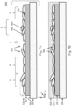
- a print construction including: (a) a printing substrate having an image-receiving surface; (b) a receptive layer, at least partially covering the image-receiving surface, and having a particle reception surface distally disposed to the image-receiving surface; and (c) a plurality of individual particles adhered to the particle reception surface, and forming a monolayer thereon.
- a metallized print construction including: (a) a printing substrate having an image-receiving surface; (b) a receptive layer, at least partially covering the image-receiving surface, and having a particle reception surface distally disposed to the image-receiving surface; and (c) a plurality of metal particles adhered to the particle reception surface, and forming a monolayer thereon.
- the plurality of particles have an average long dimension of at most 800 micrometers, the average long dimension being a number-averaged characteristic long dimension or a number-averaged maximum long dimension of the plurality of particles.
- the plurality of particles have a maximum average thickness of at most 1200 nm, the maximum average thickness being a number-averaged thickness or a number-averaged maximum thickness of the plurality of particles.
- the average long dimension is at most 600 micrometers, at most 400 ⁇ m, at most 250 ⁇ m, at most 150 ⁇ m, at most 100 ⁇ m, at most 80 ⁇ m, at most 60 ⁇ m, at most 40 ⁇ m, at most 25 ⁇ m, at most 20 ⁇ m, at most 15 ⁇ m, at most 12 ⁇ m, at most 10 ⁇ m, at most 8 ⁇ m, at most 6 ⁇ m, at most 4 ⁇ m, at most 3 ⁇ m, at most 2 ⁇ m, at most 1.5 ⁇ m, at most 1.2 ⁇ m, at most 1.0 ⁇ m, at most 0.8 ⁇ m, at most 0.7 ⁇ m, at most 0.65 ⁇ m, or at most 0.6 ⁇ m.
- the average long dimension or number-averaged long dimension is at least 0.04 micrometers, at least 0.05 ⁇ m, at least 0.06 ⁇ m, at least 0.08 ⁇ m, at least 0.10 ⁇ m, at least 0.12 ⁇ m, at least 0.15 ⁇ m, or at least 0.20 ⁇ m.
- the particles are non-hydrophobic, and a hydrophobic layer is attached to each of the particles, and at least partially envelops each of the particles.
- the hydrophobic layer is an inorganic hydrophobic layer optionally including an oxide.
- the fatty acid, oil, and oily substance have a backbone having a carbon number of at least 6, and optionally, within a range of 6 to 50, 6 to 30, 6 to 24 or 10 to 24.
- the hydrophobic layer has a thickness of at most 15 nm, at most 10 nm, at most 7 nm, at most 5 nm, at most 4 nm, at most 3 nm, at most 2.5 nm, or at most 2 nm.
- binders are present in inks in amounts correlated with the amount of metallic particles and as conventional metallic inks are typically characterized by relatively high metal loadings (e.g., of at least 20wt.%), polymeric binders generally constitute an important fraction of such inks.
- Particle compositions suitable for the present printing method need not comprise a binder (e.g., a polymeric binder).
- a printed construction obtained according to the present disclosure using such "binder-less" particle compositions is correspondingly devoid or substantially devoid of such binders.
- the presence of a binder in a printed construction can be optically assessed by microscopy techniques (e.g., confocal microscopy or AFM).
- microscopy techniques e.g., confocal microscopy or AFM.
- a top view of a printed construction comprising a binder will display a distinct continuous topology, whereas in a printed construction according to the present teachings the interstices between adjacent monolayer particles, if any, will be discernible (in absence of an overcoat that may mask such phenomena).
- the monolayer contains at most 20%, at most 15%, at most 10%, at most 5%, binder, at most 3%, or at most 2% of a binder such as a polymeric binder.
- the percentage of binder in the monolayer can be provided in weight per weight or in volume per volume, depending on the methodology elected by the skilled person to assess such presence.
- the monolayer includes a plurality of particles not adhered to the particle reception surface, the monolayer having at most 50%, at most 40%, at most 35%, at most 30%, at most 25%, at most 20%, at most 15%, at most 10%, at most 7%, at most 5%, at most 3%, or at most 2%, by number, of the particles.
- these values are obtained using field of view techniques.
- the monolayer has an optical surface coverage percentage of at least 20%, at least 50%, at least 60%, at least 70%, at least 80%, at least 90%, or at least 95%.
- the monolayer has an optical surface coverage percentage within a range of 20% to 100%, 40% to 100%, 50% to 100%, 60% to 100%, 80% to 100%, or 80% to 95%.
- the adhesive layer is disposed on solely a portion of the image-receiving surface.
- the adhesive layer is disposed on solely a portion of the image-receiving surface according to a pre-defined pattern.
- the monolayer is disposed solely on this portion of the image-receiving surface.
- the print construction further includes an overcoat covering and optionally sealing the monolayer.
- the overcoat may be a colored or uncolored transparent, translucent, or opaque layer.
- the optional overcoat satisfactorily adheres to the monolayer of particles and/or is compatible with the receptive layer underneath said monolayer. Attachment of the overcoat to the particles can be optionally enhanced by physical treatment of the surface with plasma or corona.
- the over-coat preferably enables such treatment. If, for example, a particular receptive layer requires final UV-curing following transfer of particles thereupon, an overcoat applied upon the monolayer of particles needs to permit the transmission of the UV radiation necessary to achieve such curing.
- ASPavg is evaluated in a field of view (preferably a representative field of view) containing at least 5 of the particles.
- this representative field of view contains at least 10, at least 15, or at least 20 of the particles.
- this representative field of view contains 5 to 100, 10 to 100, 10 to 50, 15 to 50, or 20 to 50 of the particles.
- equivalent diameter refers to the arithmetical average between the longest and shortest dimensions of that largest orthogonal plane.
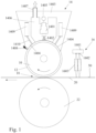
- the particles When applying to the substrate 20 an effect similar to foil imaging, the particles may be, as mentioned, metallic or more generally metal-looking and may be coated or uncoated. Because of the manner in which such particles are produced (commonly by milling), they tend to be flat platelets and though not essential this enables highly reflective coatings of near mirror quality to be achieved when the particles have light reflective surfaces and their planar dimension are substantially aligned with the surface of the substrate. Such particles lend themselves to burnishing, which may be carried our either by the use of high pressure during the spraying or by means of a burnishing roller, such as the optional roller 40 and counter roller 42 shown in Figure 2 .
- a burnishing roller or other wiping element may be positioned immediately downstream or as part of the coating apparatus 14.
- Burnishing may be carried out with a dry roller or with a wet roller (e.g., impregnated and/or washed with the fluid on which the particles are suspended, for instance water).
- a wet roller e.g., impregnated and/or washed with the fluid on which the particles are suspended, for instance water.
- an intermediate applicator it cannot be ruled out that it may, in addition to applying the particles to the surface, also at least partly burnish them. It is believed that during burnishing, the size of the particles is reduced as compared to their original size upon initial injection into the coating apparatus, and that, alternatively and additionally, the burnished particles are oriented in a substantially parallel manner with respect to the donor surface.
- the outer surface of the optional burnishing roller may rotate at a linear speed different than that of the donor surface of the drum and/or of the outer surface of an intermediate applicator, if present. It can rotate in the same or counter-direction relative to the drum.
- the particle carrier is the particle carrier
- the particle carrier that is to say the fluid within which the particles are suspended, may be either a liquid or a gas. If liquid, the carrier is preferably water based and if gaseous the carrier is preferably air.
- the particles may be lyophobic (i.e., having no affinity) with respect to their carrier, for instance may be hydrophobic, while the carrier is an aqueous liquid. Such may result in particles being partly dispersed in the liquid, and partly phase separated (all types of such mixtures of materials of same or different phases being herein encompassed by the term "suspended").
- the carrier may comprise any additive known in the art of particle formulation, such as dispersants, surfactants, water-miscible solvents, co-solvents, stabilizers, preservatives, viscosity modifiers, pH modifiers, and the like. All such additives and their typical concentrations are known to persons skilled in the art of dispersions and need not be further detailed herein. Additives (or mixtures thereof) not affecting the hydrophobicity of the particles and of the donor surface are preferred. Such agents, in particular the dispersing agents, may assist in maintaining or increasing the stability of the suspended particles in the liquid (including in phase separated form, if desired).
- the liquid carrier may also comprise excess of unbound material serving as particle coat, if desired when applicable. Any such additive and mix thereof, preferably do not affect the overall inertness of the liquid carrier towards the donor surface (e.g., avoiding or reducing any deleterious swelling of the surface that would prevent proper coating by / attachment of the particles).
- a liquid carrier is said to be aqueous if it contains at least 80wt.% water (i.e., 80% by weight of the total composition), or at least 85wt.%, or at least 90wt.%, or at least even 95wt.% water. It is to be understood that though final work aqueous compositions may predominantly contain water, as previously mentioned, it is possible to prepare intermediate aqueous compositions containing a higher amount of solid particles (and additives if any) and lower amount of water. Such intermediate compositions may serve as concentrates, which can be diluted to desired working concentrations when needed, but stored and/or shipped in smaller volumes. A concentrate may for instance comprise as much as about 80wt.% of solids and about 20wt.% of a water miscible co-solvent, the water being added during dilution of the concentrate.
- the donor surface 12 in some embodiments is a hydrophobic surface, made typically of an elastomer that can be tailored to have properties as herein disclosed, generally prepared from a silicone-based material.
- Poly(dimethylsiloxane) polymers which are silicone-based, have been found suitable.
- a fluid curable composition was formulated by combining three silicone-based polymers: a vinyl-terminated polydimethylsiloxane 5000 cSt (DMS V35, Gelest ® , CAS No.
- a platinum catalyst such as a platinum divinyltetramethyldisiloxane complex (SIP 6831.2, Gelest ® , CAS No. 68478-92-2 ) in an amount of about 0.1wt.%
- an inhibitor to better control curing conditions Inhibitor 600 of Evonik ® Hanse, in an amount of about 2.6wt.%
- a reactive cross-linker such as a methyl-hydrosiloxane- dimethylsiloxane copolymer (HMS 301, Gelest ® , CAS No.
- This addition curable composition was shortly thereafter applied with a smooth leveling knife upon the support of the donor surface (e.g.. an epoxy sleeve mountable on drum 10), such support being optionally treated (e.g., by corona or with a priming substance) to further the adherence of the donor surface material to its support.
- the applied fluid was cured for two hours at 100-120°C in a ventilated oven so as to form a donor surface.
- the hydrophobicity is to enable the particles exposed to selective stripping by the tacky film created on the receptive layer bearing substrate to transfer cleanly to the substrate without splitting.
- the donor surface should be hydrophobic, that is to say the wetting angle with the aqueous carrier of the particles should exceed 90°.
- the wetting angle is the angle formed by the meniscus at the liquid/air/solid interface and if it exceeds 90°, the water tends to bead and does not wet, and therefore adhere, to the surface.
- the wetting angle or equilibrium contact angle ⁇ 0 which is comprised between and can be calculated from the receding (minimal) contact angle ⁇ R and the advancing (maximal) contact angle ⁇ A , can be assessed at a given temperature and pressure of relevance to the operational conditions of the process.
- This hydrophobicity may be an inherent property of the polymer forming the donor surface or may be enhanced by inclusion of hydrophobicity additives in the polymer composition.
- Additives that may promote the hydrophobicity of a polymeric composition may be, for example, oils (e.g., synthetic, natural, plant or mineral oils), waxes, plasticizers and silicone additives.
- oils e.g., synthetic, natural, plant or mineral oils
- waxes e.g., synthetic, natural, plant or mineral oils
- plasticizers e.g., silicone additives.
- Such hydrophobicity additives can be compatible with any polymeric material, as long as their respective chemical nature or amounts do not prevent proper formation of the donor surface, and for instance would not impair adequate curing of the polymeric material.
- the roughness or finish of the donor surface will be replicated in the printed metallized surface. Therefore if a mirror finish or highly glossy appearance is required, the donor surface would need to be smoother than if a matte or satin look is desired. These visual effects can also be derived from the roughness of the printing substrate and/or of the receptive layer.
- the donor surface may have any Shore hardness suitable to provide a strong bond to the particles when they are applied using the coating apparatus 14, the bond being stronger than the tendency of the particles to adhere to one another.
- the hardness of the silicone-based surface may vary and for instance depend on the thickness of the donor surface and/or the particles intended to be bond. It is believed that for relatively thin donor surfaces (e.g., 100 ⁇ m or less), the silicone-based material may have a medium to low hardness; whereas for relatively thick donor surfaces (e.g., up to about 1 mm), the silicone-based material may have a relatively high hardness. Additionally, larger particles may typically benefit from a donor surface having a lower hardness than necessary to accommodate relatively smaller particles. In some embodiments, a relatively high hardness between about 60 Shore A and about 80 Shore A is suitable for the donor surface. In other embodiments, a medium-low hardness of less than 60, 50, 40, 30 or even 20 Shore A is satisfactory.
- the donor surface 12 in the drawings is the outer surface of a drum 10 but this is not essential as it may alternatively be the surface of an endless transfer member having the form of a belt guided over guide rollers and maintained under an appropriate tension at least while it is passing through the coating apparatus.
- the donor surface may additionally address practical or particular considerations resulting from the specific architecture of the printing system. For instance, it can be flexible enough to be mounted on a drum, have sufficient abrasion resistance, be inert to the particles and/or fluids being employed, and/or be resistant to any operating condition of relevance (e.g., pressure, heat, tension, etc.). Fulfilling any such property tends to favorably increase the life-span of the donor surface.
- Signals supplied to the chips for the activation of one or more laser element are synchronized with the movement of the substrate 20 towards the impression station 18 in the direction of the illustrated arrow by a transport system (not shown in Figure 1 ).
- the effect of the irradiation of each pixel by a laser beam is to convert an inactive receptive layer on the substrate 20 at that pixel into a tacky state (activating the receptive film) so that said pixel may later adhere to the particles coating the donor surface 12.
Landscapes
- Chemical & Material Sciences (AREA)
- Engineering & Computer Science (AREA)
- Organic Chemistry (AREA)
- Materials Engineering (AREA)
- Mechanical Engineering (AREA)
- Life Sciences & Earth Sciences (AREA)
- Wood Science & Technology (AREA)
- Manufacturing & Machinery (AREA)
- Chemical Kinetics & Catalysis (AREA)
- Metallurgy (AREA)
- Inorganic Chemistry (AREA)
- General Chemical & Material Sciences (AREA)
- Optics & Photonics (AREA)
- Physics & Mathematics (AREA)
- Printing Methods (AREA)
- Application Of Or Painting With Fluid Materials (AREA)
- Coating Apparatus (AREA)
- Laminated Bodies (AREA)
- Nozzles (AREA)
- Inking, Control Or Cleaning Of Printing Machines (AREA)
- Printing Plates And Materials Therefor (AREA)
- General Preparation And Processing Of Foods (AREA)
- Spray Control Apparatus (AREA)
- Formation And Processing Of Food Products (AREA)
- Manufacturing Of Printed Wiring (AREA)
- Finishing Walls (AREA)
- Ink Jet (AREA)
- Thermal Transfer Or Thermal Recording In General (AREA)
Applications Claiming Priority (6)
| Application Number | Priority Date | Filing Date | Title |
|---|---|---|---|
| GBGB1509080.6A GB201509080D0 (en) | 2015-05-27 | 2015-05-27 | Coating apparatus |
| GBGB1514619.4A GB201514619D0 (en) | 2015-05-27 | 2015-08-17 | Printing system and method |
| GBGB1514618.6A GB201514618D0 (en) | 2015-05-27 | 2015-08-17 | Coating apparatus |
| GB1603997.6A GB2536361B (en) | 2015-05-27 | 2016-03-08 | Printing system and method |
| GBGB1604989.2A GB201604989D0 (en) | 2015-05-27 | 2016-03-23 | Printing system and method and printed constructions thereof |
| PCT/IB2016/053154 WO2016189519A1 (en) | 2015-05-27 | 2016-05-27 | Metal printed constructions |
Publications (3)
| Publication Number | Publication Date |
|---|---|
| EP3302990A1 EP3302990A1 (en) | 2018-04-11 |
| EP3302990C0 EP3302990C0 (en) | 2025-07-09 |
| EP3302990B1 true EP3302990B1 (en) | 2025-07-09 |
Family
ID=53540974
Family Applications (4)
| Application Number | Title | Priority Date | Filing Date |
|---|---|---|---|
| EP16735689.8A Active EP3302990B1 (en) | 2015-05-27 | 2016-05-27 | Metal printed constructions |
| EP16734454.8A Active EP3302978B1 (en) | 2015-05-27 | 2016-05-27 | Coating apparatus |
| EP16732756.8A Active EP3302976B1 (en) | 2015-05-27 | 2016-05-27 | Printing system and method |
| EP16732757.6A Active EP3302977B1 (en) | 2015-05-27 | 2016-05-27 | Coating apparatus |
Family Applications After (3)
| Application Number | Title | Priority Date | Filing Date |
|---|---|---|---|
| EP16734454.8A Active EP3302978B1 (en) | 2015-05-27 | 2016-05-27 | Coating apparatus |
| EP16732756.8A Active EP3302976B1 (en) | 2015-05-27 | 2016-05-27 | Printing system and method |
| EP16732757.6A Active EP3302977B1 (en) | 2015-05-27 | 2016-05-27 | Coating apparatus |
Country Status (15)
| Country | Link |
|---|---|
| US (7) | US10906064B2 (https=) |
| EP (4) | EP3302990B1 (https=) |
| JP (4) | JP2018517596A (https=) |
| KR (4) | KR102521445B1 (https=) |
| CN (4) | CN107848315B (https=) |
| AU (4) | AU2016268517B2 (https=) |
| BR (3) | BR112017025399B1 (https=) |
| CA (4) | CA2987195A1 (https=) |
| ES (3) | ES2807830T3 (https=) |
| GB (5) | GB201509080D0 (https=) |
| IL (4) | IL255947B2 (https=) |
| MX (5) | MX389269B (https=) |
| PL (2) | PL3302977T3 (https=) |
| RU (4) | RU2722435C2 (https=) |
| WO (4) | WO2016189513A1 (https=) |
Families Citing this family (39)
| Publication number | Priority date | Publication date | Assignee | Title |
|---|---|---|---|---|
| MX372575B (es) * | 2015-05-27 | 2020-04-16 | Landa Labs 2012 Ltd | Metodo y aparato de impresion para el recubrimiento de regiones seleccionadas de un sustrato con una pelicula |
| GB201509080D0 (en) | 2015-05-27 | 2015-07-08 | Landa Labs 2012 Ltd | Coating apparatus |
| PT3302985T (pt) | 2015-05-27 | 2021-01-13 | Landa Labs 2012 Ltd | Dispositivo de formação de imagens |
| US11701684B2 (en) | 2015-05-27 | 2023-07-18 | Landa Labs (2012) Ltd. | Method for coating a surface with a transferable layer of thermoplastic particles and related apparatus |
| FR3053126B1 (fr) * | 2016-06-27 | 2019-07-26 | Saint-Gobain Glass France | Procede et dispositif de localisation de l'origine d'un defaut affectant un empilement de couches minces deposees sur un substrat |
| EP3324426B1 (en) | 2016-11-16 | 2021-05-05 | ATOTECH Deutschland GmbH | Transport roller |
| CN110023092B (zh) * | 2016-11-30 | 2021-08-20 | 兰达实验室(2012)有限公司 | 热转印打印的改进 |
| CN106739459A (zh) * | 2016-12-16 | 2017-05-31 | 上海正伟印刷有限公司 | 一种仿真烫印效果的印刷方法及其实现该方法的印刷装置 |
| DE102018209524A1 (de) * | 2017-07-13 | 2019-01-17 | Heidelberger Druckmaschinen Ag | Verfahren zum Vorbehandeln eines Bedruckstoffs für den Tintendruck |
| GB201712726D0 (en) * | 2017-08-08 | 2017-09-20 | Landa Labs (2012) Ltd | Electric current and heat mitigation in a printing machine writing module |
| JP7252716B2 (ja) * | 2018-05-18 | 2023-04-05 | 株式会社ミマキエンジニアリング | 金属調光沢を呈する印刷物の製造方法、金属調光沢を呈する印刷物、及びインクジェットプリンタ |
| GB2574439B (en) * | 2018-06-06 | 2020-06-10 | Landa Labs 2012 Ltd | Thermal transfer printing system and method |
| AU2019299445B2 (en) | 2018-07-06 | 2025-06-26 | Hasbro, Inc. | Fabric printing method for producing sparkling fabric |
| WO2020016171A1 (en) | 2018-07-16 | 2020-01-23 | Eckart Gmbh | Pvd-aluminum pigment dispersion and cosmetic formulations |
| JP2020094879A (ja) * | 2018-12-11 | 2020-06-18 | コニカミノルタ株式会社 | 加飾印刷検査装置、加飾印刷検査システム、加飾印刷検査方法、及び、プログラム |
| US12305291B2 (en) * | 2019-01-11 | 2025-05-20 | East China Jiaotong University | Super-hydrophobic manganese dioxide coating on metallic material surfaces |
| CN110058725B (zh) * | 2019-03-06 | 2021-11-05 | 苏州蓝沛光电科技有限公司 | 触控屏的制备方法 |
| CN110045864B (zh) * | 2019-03-06 | 2021-11-05 | 苏州蓝沛光电科技有限公司 | 种子层的制备方法 |
| TWI760709B (zh) * | 2019-04-05 | 2022-04-11 | 瑞士商巴柏斯特麥克斯合資公司 | 燙金印刷機 |
| JP7221781B2 (ja) * | 2019-04-26 | 2023-02-14 | 株式会社Screenホールディングス | 印刷版位置決め装置および画像記録装置 |
| JP7387307B2 (ja) * | 2019-06-27 | 2023-11-28 | キヤノン株式会社 | 記録装置、記録方法、及びプログラム |
| KR102218373B1 (ko) * | 2019-08-05 | 2021-02-19 | 주식회사 포스코 | 롤의 이물질 제거장치 |
| US12360294B2 (en) * | 2019-09-03 | 2025-07-15 | National Research Council Of Canada | 3D printed graded refractive index device |
| CN110479536B (zh) * | 2019-09-12 | 2024-04-26 | 深圳劲嘉新型智能包装有限公司 | 一种丝印组装机 |
| EP3851210B1 (en) * | 2020-01-14 | 2025-12-24 | Jesús Francisco Barberan Latorre | Applicator roller |
| CN111114162B (zh) * | 2020-01-19 | 2021-07-09 | 昆山美普森包装有限公司 | 一种高精度免版烫印工艺 |
| CN111036502A (zh) * | 2020-03-11 | 2020-04-21 | 龙游讴凡纳米材料有限公司 | 一种纳米板材表面抛光处理及辊涂设备 |
| GB2594052A (en) * | 2020-04-07 | 2021-10-20 | Landa Labs 2012 Ltd | Apparatus for coating a surface with particles |
| CN111530694A (zh) * | 2020-06-05 | 2020-08-14 | 福建卫东新能源股份有限公司 | 一种电池极片涂覆装置 |
| CN112009089B (zh) * | 2020-09-16 | 2022-04-26 | 江苏正红彩印有限公司 | 一种带有组合式接触送料印刷辊的印刷设备 |
| EP4228902A1 (en) | 2020-10-19 | 2023-08-23 | ACTEGA Metal Print | Process for printing particles |
| WO2022148658A1 (en) * | 2021-01-11 | 2022-07-14 | Eckart Gmbh | Silica encapsulated pigments for nano-metallography |
| DE102021125055A1 (de) * | 2021-09-28 | 2023-03-30 | Heidelberger Druckmaschinen Aktiengesellschaft | Verfahren zur Herstellung mechanisch robuster farbmittelhaltiger Beschichtungen |
| DE102022126240A1 (de) * | 2021-11-17 | 2023-05-17 | Heidelberger Druckmaschinen Aktiengesellschaft | Verfahren zum Herstellen eines Druckprodukts |
| JP7754192B2 (ja) * | 2021-11-19 | 2025-10-15 | 株式会社村田製作所 | グラビア印刷装置 |
| JP2023084243A (ja) * | 2021-12-07 | 2023-06-19 | コニカミノルタ株式会社 | 画像形成装置、及び、画像形成方法 |
| WO2023118321A1 (en) | 2021-12-22 | 2023-06-29 | Eckart Gmbh | Metal effect pigments coated with additives for nanometallography printing |
| DE102022128629A1 (de) * | 2022-10-28 | 2024-05-08 | Airbus Defence and Space GmbH | Beschichtungsmaterial für eine Oberfläche eines Fluggeräts mit Blitzschutz |
| WO2025057054A1 (en) * | 2023-09-11 | 2025-03-20 | Landa Labs (2012) Ltd | Method and apparatus for 3d printing |
Family Cites Families (126)
| Publication number | Priority date | Publication date | Assignee | Title |
|---|---|---|---|---|
| US1905959A (en) | 1928-12-14 | 1933-04-25 | Goodlass Wall And Lead Ind Ltd | Metal coated material |
| GB712437A (en) | 1950-12-20 | 1954-07-21 | Philippe Lebuy | Improved method and apparatus for printing fabrics with metallization |
| US3127668A (en) | 1955-03-03 | 1964-04-07 | Iit Res Inst | High strength-variable porosity sintered metal fiber articles and method of making the same |
| US3063216A (en) * | 1955-09-21 | 1962-11-13 | Silverman Leslie | Method and apparatus for forming and utilizing a filter medium |
| BE567069A (https=) | 1957-04-25 | |||
| US3264132A (en) | 1962-02-06 | 1966-08-02 | Little Inc A | Method for applying metallic flake material to a substrate |
| DE2030595A1 (de) * | 1970-06-20 | 1972-01-05 | Herberts & Co Gmbh Dr Kurt | Verfahren und Vorrichtung zum Beschichten von Bandmaterialien mit pulverförmigen Überzugsmitteln |
| SU831055A3 (ru) | 1975-07-23 | 1981-05-15 | Куфнер Текстильверке Кг (Фирма) | Способ нанесени порошкообразногоКлЕ HA лЕНТОчНый МАТЕРиАл и уСТРОйСТВО дл ЕгО ОСущЕСТВлЕНи |
| DE2851008A1 (de) | 1978-11-24 | 1980-05-29 | Bhs Bayerische Berg | Vorrichtung zum dosieren des leimauftrages auf eine laufende bahn, insbesondere wellpappenbahn |
| DE3029521A1 (de) | 1980-08-04 | 1982-03-04 | Helmuth 2058 Lauenburg Schmoock | Schaltung mit aufgedruckten leiterbahnen und verfahren zu deren herstellung |
| JPS57135073A (en) * | 1981-02-14 | 1982-08-20 | Matsushita Electric Works Ltd | Production of building plate |
| US4687531A (en) | 1982-01-26 | 1987-08-18 | Potoczky Joseph B | Method for centrifugal spray molding of thin-walled structures |
| DE3211166A1 (de) * | 1982-03-26 | 1983-09-29 | Merck Patent Gmbh, 6100 Darmstadt | Verfahren zur hydrophobierung von perlglanzpigmenten |
| GB8401838D0 (en) * | 1984-01-24 | 1984-02-29 | Tribohesion Ltd | Coating process |
| JPS60171586A (ja) | 1984-02-17 | 1985-09-05 | Tamura Electric Works Ltd | 電磁カウンタ |
| JPS60245589A (ja) * | 1984-05-22 | 1985-12-05 | Takeshi Kojima | 粒径が異る微小粒子のコ−テイング方法 |
| JPS6168253A (ja) | 1984-09-12 | 1986-04-08 | Fuji Xerox Co Ltd | インクジエツト記録装置 |
| DE3511146A1 (de) | 1985-03-27 | 1986-10-02 | Heinz Deuschle Graphische Werkstätten GmbH, 7320 Göppingen | Verfahren und vorrichtung zur uebertragung optisch wirksamer teile einer folienschicht auf einen bedruckstoff |
| US5177124A (en) | 1987-08-19 | 1993-01-05 | Intaglio Ltd. | Plastic molded pieces having the appearance of a solid metallic piece |
| DE3910481A1 (de) | 1988-04-02 | 1989-10-19 | Ricoh Kk | Bildfixierungseinheit zur verwendung in einem elektrophotographischen nasskopiergeraet |
| US5083710A (en) | 1988-09-06 | 1992-01-28 | Oxy-Dry Corporation | Powder sprayer with automatic powder supply system |
| ATE99746T1 (de) | 1988-10-28 | 1994-01-15 | Kufner Textilwerke Gmbh | Verfahren und vorrichtung zum rasterfoermigen beschichten von flexiblen flaechengebilden und deren fertigungsprodukte. |
| DE4110801C1 (https=) * | 1991-04-04 | 1992-05-27 | Kurt 4040 Neuss De Lappe | |
| GB9120444D0 (en) * | 1991-09-25 | 1991-11-06 | Markem Syst Ltd | Printing apparatus and process |
| US5487927A (en) | 1992-01-24 | 1996-01-30 | Revlon Consumer Products Corporation | Decorating method and products |
| US5751327A (en) | 1993-06-18 | 1998-05-12 | Xeikon N.V. | Printer including temperature controlled LED recording heads |
| GB9409629D0 (en) | 1994-05-13 | 1994-07-06 | Prittie Allan R | Method and apparatus for foil transfer |
| GB9524502D0 (en) | 1995-11-30 | 1996-01-31 | Elfglade Ltd | Transfer printing method and apparatus |
| US5653794A (en) | 1995-12-01 | 1997-08-05 | Scm Chemicals, Inc. | Silane treated inorganic pigments |
| US6469728B1 (en) | 1995-12-18 | 2002-10-22 | Xerox Corporation | LED printbars with depth of focus enhancement |
| JPH1070151A (ja) | 1996-08-26 | 1998-03-10 | Ricoh Co Ltd | 導電粒子の配列方法及びその装置 |
| JP3052127B2 (ja) | 1996-11-22 | 2000-06-12 | 東京コパル化学株式会社 | ロールコーティング装置 |
| DE19707157B4 (de) | 1997-02-22 | 2006-04-06 | Weitmann & Konrad Gmbh & Co Kg | Vorrichtung zum Bestäuben von bewegten flächigen Produkten |
| DE19748821A1 (de) | 1997-11-05 | 1999-05-06 | Itw Gema Ag | Pulver-Sprühbeschichtungsvorrichtung |
| DE19753266B4 (de) * | 1997-12-01 | 2010-10-07 | H.B. Fuller Licensing & Financing, Inc., St. Paul | Verfahren zum Verbinden luftundurchlässiger Materialien |
| JPH11188921A (ja) | 1997-12-25 | 1999-07-13 | Brother Ind Ltd | 露光装置 |
| GB2353532B (en) * | 1998-03-23 | 2001-08-01 | Api Foils Ltd | Hot dieless foiling |
| GB9813205D0 (en) | 1998-06-18 | 1998-08-19 | Rue De Int Ltd | Methods of providing images on substrates |
| US6623816B1 (en) * | 1998-11-18 | 2003-09-23 | Ricoh Company, Ltd. | Recording method and apparatus with an intermediate transfer medium based on transfer-type recording mechanism |
| KR100405300B1 (ko) | 1999-03-04 | 2003-11-12 | 주식회사 엘지화학 | 위치 선정성 및 재부착 특성이 우수한 점착 시트 및 그의 제조방법 |
| US6620234B1 (en) * | 1999-11-12 | 2003-09-16 | Millennium Inorganic Chemicals, Inc. | Processes for preparing hydrophobic inorganic oxide pigments |
| WO2001082003A1 (en) | 2000-04-21 | 2001-11-01 | Pfu Limited | Liquid development electrophotographic apparatus |
| US20020119255A1 (en) | 2000-05-09 | 2002-08-29 | Ranjith Divigalpitiya | Method and apparatus for making particle-embedded webs |
| US6569494B1 (en) * | 2000-05-09 | 2003-05-27 | 3M Innovative Properties Company | Method and apparatus for making particle-embedded webs |
| TW572832B (en) * | 2000-06-12 | 2004-01-21 | Tomoegawa Paper Co Ltd | Process for preparation of single powder film on long ruler-like film substrate and apparatus for preparing the same |
| JP3712923B2 (ja) * | 2000-08-04 | 2005-11-02 | 株式会社巴川製紙所 | 粉体層積層体の製造方法及びその製造装置 |
| US6660326B2 (en) * | 2000-08-04 | 2003-12-09 | Tomoegawa Paper Co. Ltd. | Production method for monolayer powder film and production apparatus therefor |
| GB2368313B (en) | 2000-10-28 | 2004-03-03 | Blockfoil Group Ltd | Cold foil stamping |
| JP3681978B2 (ja) * | 2000-12-19 | 2005-08-10 | 株式会社巴川製紙所 | 光反射板および反射型液晶表示装置 |
| JP2002254696A (ja) | 2001-03-02 | 2002-09-11 | Dainippon Screen Mfg Co Ltd | Led露光ヘッド装置 |
| US7669547B2 (en) * | 2001-03-14 | 2010-03-02 | 3M Innovative Properties Company | Coating apparatus |
| US6487002B1 (en) | 2001-06-11 | 2002-11-26 | Xerox Corporation | Large area micro-structure template for creation of closely packed arrays |
| JP2005502121A (ja) | 2001-08-31 | 2005-01-20 | アルキヴィオ・インコーポレーテッド | 記憶ポリシに基づいてデータを記憶する技法 |
| US6719423B2 (en) | 2001-10-09 | 2004-04-13 | Nexpress Solutions Llc | Ink jet process including removal of excess liquid from an intermediate member |
| US6682189B2 (en) | 2001-10-09 | 2004-01-27 | Nexpress Solutions Llc | Ink jet imaging via coagulation on an intermediate member |
| AT412681B (de) | 2002-04-22 | 2005-05-25 | Hueck Folien Gmbh | Substrate mit unsichtbaren elektrisch leitfähigen schichten |
| US20100208351A1 (en) | 2002-07-15 | 2010-08-19 | Nofi Michael R | Selective and oriented assembly of platelet materials and functional additives |
| US7239836B2 (en) | 2002-08-23 | 2007-07-03 | Kyocera Mita Corporation | Fixing apparatus |
| JP4023258B2 (ja) | 2002-08-30 | 2007-12-19 | コニカミノルタホールディングス株式会社 | インクジェット記録用紙の製造方法及び製造装置 |
| US7002613B2 (en) | 2002-09-06 | 2006-02-21 | Heidelberger Druckmaschinen Ag | Method for printing an image on a printing substrate and device for inputting energy to a printing-ink carrier |
| US20040223929A1 (en) | 2003-05-08 | 2004-11-11 | The Procter & Gamble Company | Personal care compositions containing hydrophobically modified interference pigments |
| JP2005004038A (ja) * | 2003-06-13 | 2005-01-06 | Fuji Photo Film Co Ltd | 画像記録材料用支持体及びその製造方法 |
| ITBO20030450A1 (it) * | 2003-07-29 | 2005-01-30 | Gd Spa | Unita'di alimentazione di un nastro di materiale di incarto. |
| US20060003097A1 (en) | 2003-08-06 | 2006-01-05 | Andres Ronald P | Fabrication of nanoparticle arrays |
| JP2005140945A (ja) | 2003-11-06 | 2005-06-02 | Canon Inc | 帯電ローラ、帯電ローラの製造方法及び画像形成装置 |
| US7846510B2 (en) | 2004-05-03 | 2010-12-07 | Amir Afshar | Methods and compositions for forming a specular coating film |
| DE502005001287D1 (de) | 2004-07-28 | 2007-10-04 | Andritz Kuesters Gmbh & Co Kg | Vorrichtung zum Auftrag von Abschnitten von Flotte auf eine laufende Warenbahn |
| US20060046005A1 (en) | 2004-08-24 | 2006-03-02 | Mcgee Dennis E | Coating for polymeric labels |
| US7061581B1 (en) | 2004-11-22 | 2006-06-13 | Asml Netherlands B.V. | Lithographic apparatus and device manufacturing method |
| US7625605B2 (en) | 2004-12-30 | 2009-12-01 | 3M Innovative Properties Company | Method for coating a surface with a pattern of coating fluid |
| JP2006263537A (ja) | 2005-03-23 | 2006-10-05 | Konica Minolta Photo Imaging Inc | 表面層のスプレー塗布方法、表面層塗布用のスプレー塗布装置、インクジェット記録用紙 |
| JP2006306998A (ja) * | 2005-04-28 | 2006-11-09 | Sekisui Chem Co Ltd | 光干渉樹脂微粒子及び光干渉複合微粒子 |
| JP2007038142A (ja) * | 2005-08-03 | 2007-02-15 | Casio Electronics Co Ltd | 粉体接着剤塗布方法 |
| CA2520442A1 (en) * | 2005-09-15 | 2007-03-15 | Hamish Somerville | Vacuum metalized pigment patterns and method of making same |
| ITMO20060058A1 (it) * | 2006-02-21 | 2007-08-22 | Mira Di Algeri Maris | Metodo per decorare, relativo apparato ed elemento |
| US20070281136A1 (en) | 2006-05-31 | 2007-12-06 | Cabot Corporation | Ink jet printed reflective features and processes and inks for making them |
| JP4250651B2 (ja) | 2006-09-28 | 2009-04-08 | 株式会社東芝 | 粒子配列方法、及び、発光素子の製造方法 |
| EP2089478B1 (en) * | 2006-12-05 | 2016-01-27 | Basf Se | Surface-modified (effect) pigments |
| US7881358B2 (en) | 2006-12-27 | 2011-02-01 | Nec Corporation | Surface emitting laser |
| JP5144243B2 (ja) * | 2006-12-28 | 2013-02-13 | 富士フイルム株式会社 | 画像形成方法及び画像形成装置 |
| JP2008173889A (ja) | 2007-01-19 | 2008-07-31 | Seiko Epson Corp | ラインヘッド及び該ラインヘッドを用いた画像形成装置 |
| US20080187691A1 (en) * | 2007-02-07 | 2008-08-07 | S.D. Warren Company | Rapid Ink Drying Papers |
| JP2008194897A (ja) | 2007-02-09 | 2008-08-28 | Casio Comput Co Ltd | 発光装置及び印刷装置 |
| US7995085B2 (en) | 2007-07-04 | 2011-08-09 | Seiko Epson Corporation | Line head, and an image forming apparatus using the line head |
| JP5256792B2 (ja) | 2007-07-04 | 2013-08-07 | セイコーエプソン株式会社 | ラインヘッド及び該ラインヘッドを用いた画像形成装置 |
| DE602007011610D1 (de) | 2007-09-14 | 2011-02-10 | Punch Graphix Int Nv | Lichtemittierendes Array zum Drucken oder Kopieren |
| JP2009132039A (ja) | 2007-11-30 | 2009-06-18 | Seiko Epson Corp | 発光装置および電子機器 |
| JP5203065B2 (ja) | 2008-06-24 | 2013-06-05 | 富士フイルム株式会社 | 液体塗布方法及び画像形成装置 |
| JP2010076388A (ja) | 2008-09-29 | 2010-04-08 | Seiko Epson Corp | 画像形成装置および画像形成方法 |
| WO2010077779A2 (en) * | 2008-12-17 | 2010-07-08 | Saint-Gobain Ceramics & Plastics, Inc. | Applications of shaped nano alumina hydrate in inkjet paper |
| CN101488531B (zh) * | 2009-02-27 | 2010-12-08 | 湖南大学 | 一种硅基薄膜太阳能电池及其制作方法 |
| WO2010117102A1 (ko) | 2009-04-09 | 2010-10-14 | 서강대학교 산학협력단 | 콜로이드 입자들을 단결정들로 정렬하는 방법 |
| US20120285617A1 (en) | 2009-09-25 | 2012-11-15 | Sumitomo Chemical Company, Limited | Method for producing metal foil laminate |
| JP2011201249A (ja) * | 2010-03-26 | 2011-10-13 | Citizen Holdings Co Ltd | 熱転写プリンタ |
| WO2011129965A1 (en) * | 2010-04-12 | 2011-10-20 | Exxonmobil Oil Corporation | Coating for polymeric labels |
| JP2012066227A (ja) | 2010-09-27 | 2012-04-05 | Toppan Printing Co Ltd | グラビア塗布装置 |
| US20120103212A1 (en) * | 2010-10-29 | 2012-05-03 | Palo Alto Research Center Incorporated | Variable Data Lithography System |
| WO2012082536A2 (en) | 2010-12-17 | 2012-06-21 | 3M Innovative Properties Company | Transfer article having multi-sized particles and methods |
| JP5866887B2 (ja) | 2011-01-27 | 2016-02-24 | 富士ゼロックス株式会社 | 発光素子ヘッドおよび画像形成装置 |
| JP5202663B2 (ja) * | 2011-02-21 | 2013-06-05 | 富士フイルム株式会社 | マット剤塗布装置およびインクジェット記録装置 |
| JP5479386B2 (ja) | 2011-02-21 | 2014-04-23 | 富士フイルム株式会社 | マット剤塗布装置およびインクジェット記録装置 |
| JP2012179724A (ja) * | 2011-02-28 | 2012-09-20 | Fujifilm Corp | 印刷方法およびインクジェット記録装置 |
| KR101255780B1 (ko) | 2011-04-11 | 2013-04-17 | 서강대학교산학협력단 | 보울-형태 구조체, 이의 제조 방법, 및 보울 어레이 |
| GB201108344D0 (en) | 2011-05-18 | 2011-06-29 | Cambridge Entpr Ltd | Optical device |
| US9520012B2 (en) | 2011-05-25 | 2016-12-13 | Bby Solutions, Inc. | Retail location robotic wall system and mobile retail sales vehicle |
| US9251458B2 (en) | 2011-09-11 | 2016-02-02 | Féinics Amatech Teoranta | Selective deposition of magnetic particles and using magnetic material as a carrier medium to deposit nanoparticles |
| DE102011056761A1 (de) | 2011-12-21 | 2013-08-08 | Leibniz-Institut Für Neue Materialien Gemeinnützige Gmbh | Pigmentiertes, feinstrukturiertes tribologisches Kompositmaterial |
| JP2013153007A (ja) * | 2012-01-24 | 2013-08-08 | Murata Mfg Co Ltd | 電子部品およびその製造方法 |
| EP2822778B1 (en) | 2012-03-05 | 2019-05-08 | Landa Corporation Ltd. | Digital printing process |
| SMT201700613T1 (it) | 2012-03-06 | 2018-03-08 | Amcor Group Gmbh | Processo di stampa multi-strato |
| JP5880149B2 (ja) | 2012-03-07 | 2016-03-08 | セイコーエプソン株式会社 | 記録物の製造方法および記録物の製造装置 |
| US8939551B2 (en) | 2012-03-28 | 2015-01-27 | Eastman Kodak Company | Digital drop patterning device and method |
| DE102012207148B4 (de) * | 2012-04-27 | 2015-06-25 | Eltex-Elektrostatik Gmbh | Vorrichtung und Verfahren zum Beeinflussen von Flüssigkeitströpfchen oder Partikeln am Walzenauslauf eines Walzenpaares |
| WO2013191535A1 (en) | 2012-05-24 | 2013-12-27 | Selmers Holding Bv | Apparatus for powder coating of a surface, more in particular for powder coating of the surface of a steel pipe |
| US8840238B2 (en) * | 2012-08-30 | 2014-09-23 | Xerox Corporation | Systems and methods for ink-based digital printing using imaging member and image transfer member |
| US20140111595A1 (en) | 2012-10-19 | 2014-04-24 | Zink Imaging, Inc. | Thermal printer with dual time-constant heat sink |
| US9280583B2 (en) | 2012-11-30 | 2016-03-08 | International Business Machines Corporation | Scalable multi-query optimization for SPARQL |
| US9174432B2 (en) | 2012-12-17 | 2015-11-03 | Xerox Corporation | Wetting enhancement coating on intermediate transfer member (ITM) for aqueous inkjet intermediate transfer architecture |
| JP2014168946A (ja) | 2013-02-05 | 2014-09-18 | Seiko Epson Corp | インクジェット記録方法、インクジェット記録装置、および記録物 |
| JP2015079586A (ja) * | 2013-10-15 | 2015-04-23 | デクセリアルズ株式会社 | 異方性導電フィルム |
| US10195638B2 (en) * | 2013-10-30 | 2019-02-05 | Samsung Sdi Co., Ltd. | Apparatus for coating a separator having collection chamber and method for coating the separator |
| MX372575B (es) * | 2015-05-27 | 2020-04-16 | Landa Labs 2012 Ltd | Metodo y aparato de impresion para el recubrimiento de regiones seleccionadas de un sustrato con una pelicula |
| GB201509082D0 (en) | 2015-05-27 | 2015-07-08 | Landa Labs 2012 Ltd | Coating process |
| PT3302985T (pt) | 2015-05-27 | 2021-01-13 | Landa Labs 2012 Ltd | Dispositivo de formação de imagens |
| GB201509080D0 (en) | 2015-05-27 | 2015-07-08 | Landa Labs 2012 Ltd | Coating apparatus |
| US10244046B2 (en) | 2016-11-28 | 2019-03-26 | T-Mobile Usa, Inc. | Managing traffic at a node within a wireless communication network upon the node entering service |
-
2015
- 2015-05-27 GB GBGB1509080.6A patent/GB201509080D0/en not_active Ceased
- 2015-08-17 GB GBGB1514618.6A patent/GB201514618D0/en not_active Ceased
- 2015-08-17 GB GBGB1514619.4A patent/GB201514619D0/en not_active Ceased
-
2016
- 2016-03-08 GB GB1603997.6A patent/GB2536361B/en active Active
- 2016-03-23 GB GBGB1604989.2A patent/GB201604989D0/en not_active Ceased
- 2016-05-27 JP JP2018513936A patent/JP2018517596A/ja active Pending
- 2016-05-27 AU AU2016268517A patent/AU2016268517B2/en active Active
- 2016-05-27 PL PL16732757.6T patent/PL3302977T3/pl unknown
- 2016-05-27 EP EP16735689.8A patent/EP3302990B1/en active Active
- 2016-05-27 WO PCT/IB2016/053140 patent/WO2016189513A1/en not_active Ceased
- 2016-05-27 PL PL16735689.8T patent/PL3302990T3/pl unknown
- 2016-05-27 KR KR1020177037227A patent/KR102521445B1/ko active Active
- 2016-05-27 CN CN201680044105.4A patent/CN107848315B/zh active Active
- 2016-05-27 US US15/577,171 patent/US10906064B2/en active Active
- 2016-05-27 EP EP16734454.8A patent/EP3302978B1/en active Active
- 2016-05-27 ES ES16732756T patent/ES2807830T3/es active Active
- 2016-05-27 AU AU2016268516A patent/AU2016268516B2/en active Active
- 2016-05-27 MX MX2017015243A patent/MX389269B/es unknown
- 2016-05-27 BR BR112017025399-2A patent/BR112017025399B1/pt active IP Right Grant
- 2016-05-27 MX MX2017015159A patent/MX387631B/es unknown
- 2016-05-27 US US15/577,134 patent/US10751750B2/en active Active
- 2016-05-27 CN CN201680030801.XA patent/CN107666967B/zh active Active
- 2016-05-27 BR BR112017025310-0A patent/BR112017025310B1/pt active IP Right Grant
- 2016-05-27 EP EP16732756.8A patent/EP3302976B1/en active Active
- 2016-05-27 IL IL255947A patent/IL255947B2/en unknown
- 2016-05-27 KR KR1020177035279A patent/KR102332683B1/ko active Active
- 2016-05-27 CA CA2987195A patent/CA2987195A1/en active Pending
- 2016-05-27 RU RU2017145997A patent/RU2722435C2/ru active
- 2016-05-27 CA CA2987183A patent/CA2987183C/en active Active
- 2016-05-27 RU RU2017145999A patent/RU2715956C2/ru active
- 2016-05-27 CA CA2987198A patent/CA2987198C/en active Active
- 2016-05-27 US US15/577,262 patent/US10981191B2/en active Active
- 2016-05-27 ES ES16732757T patent/ES3043232T3/es active Active
- 2016-05-27 CN CN201680044067.2A patent/CN107921777B/zh active Active
- 2016-05-27 RU RU2017145998A patent/RU2717675C1/ru active
- 2016-05-27 MX MX2017015161A patent/MX391362B/es unknown
- 2016-05-27 KR KR1020177037251A patent/KR20180012314A/ko not_active Abandoned
- 2016-05-27 JP JP2018513939A patent/JP7182461B2/ja active Active
- 2016-05-27 MX MX2017015160A patent/MX2017015160A/es unknown
- 2016-05-27 JP JP2017561393A patent/JP6783252B2/ja active Active
- 2016-05-27 EP EP16732757.6A patent/EP3302977B1/en active Active
- 2016-05-27 CA CA2986527A patent/CA2986527C/en active Active
- 2016-05-27 WO PCT/IB2016/053154 patent/WO2016189519A1/en not_active Ceased
- 2016-05-27 KR KR1020177037249A patent/KR102521446B1/ko active Active
- 2016-05-27 WO PCT/IB2016/053145 patent/WO2016189515A1/en not_active Ceased
- 2016-05-27 WO PCT/IB2016/053146 patent/WO2016189516A1/en not_active Ceased
- 2016-05-27 ES ES16735689T patent/ES3042367T3/es active Active
- 2016-05-27 AU AU2016268520A patent/AU2016268520B2/en active Active
- 2016-05-27 BR BR112017025411-5A patent/BR112017025411B1/pt active IP Right Grant
- 2016-05-27 JP JP2018513937A patent/JP6887423B2/ja active Active
- 2016-05-27 RU RU2017138080A patent/RU2717896C2/ru active
- 2016-05-27 AU AU2016268514A patent/AU2016268514C1/en active Active
- 2016-05-27 CN CN201680044579.9A patent/CN107848292A/zh active Pending
- 2016-11-29 US US15/363,615 patent/US10960432B2/en active Active
- 2016-11-29 US US15/362,983 patent/US10583455B2/en active Active
-
2017
- 2017-11-21 IL IL255826A patent/IL255826B/en unknown
- 2017-11-21 IL IL255828A patent/IL255828B/en unknown
- 2017-11-21 IL IL255824A patent/IL255824B/en unknown
- 2017-11-27 MX MX2021013044A patent/MX2021013044A/es unknown
-
2020
- 2020-07-16 US US16/930,685 patent/US11517936B2/en active Active
- 2020-12-02 US US17/109,217 patent/US11679408B2/en active Active
Also Published As
Similar Documents
| Publication | Publication Date | Title |
|---|---|---|
| EP3302990B1 (en) | Metal printed constructions |
Legal Events
| Date | Code | Title | Description |
|---|---|---|---|
| STAA | Information on the status of an ep patent application or granted ep patent |
Free format text: STATUS: THE INTERNATIONAL PUBLICATION HAS BEEN MADE |
|
| PUAI | Public reference made under article 153(3) epc to a published international application that has entered the european phase |
Free format text: ORIGINAL CODE: 0009012 |
|
| STAA | Information on the status of an ep patent application or granted ep patent |
Free format text: STATUS: REQUEST FOR EXAMINATION WAS MADE |
|
| 17P | Request for examination filed |
Effective date: 20180102 |
|
| AK | Designated contracting states |
Kind code of ref document: A1 Designated state(s): AL AT BE BG CH CY CZ DE DK EE ES FI FR GB GR HR HU IE IS IT LI LT LU LV MC MK MT NL NO PL PT RO RS SE SI SK SM TR |
|
| AX | Request for extension of the european patent |
Extension state: BA ME |
|
| DAV | Request for validation of the european patent (deleted) | ||
| DAX | Request for extension of the european patent (deleted) | ||
| STAA | Information on the status of an ep patent application or granted ep patent |
Free format text: STATUS: EXAMINATION IS IN PROGRESS |
|
| 17Q | First examination report despatched |
Effective date: 20210601 |
|
| GRAP | Despatch of communication of intention to grant a patent |
Free format text: ORIGINAL CODE: EPIDOSNIGR1 |
|
| STAA | Information on the status of an ep patent application or granted ep patent |
Free format text: STATUS: GRANT OF PATENT IS INTENDED |
|
| RIC1 | Information provided on ipc code assigned before grant |
Ipc: B41F 19/00 20060101ALI20241223BHEP Ipc: B44C 1/00 20060101ALI20241223BHEP Ipc: B44F 9/10 20060101ALI20241223BHEP Ipc: B41C 1/18 20060101ALI20241223BHEP Ipc: B41M 1/00 20060101ALI20241223BHEP Ipc: B41M 3/00 20060101AFI20241223BHEP |
|
| INTG | Intention to grant announced |
Effective date: 20250121 |
|
| GRAS | Grant fee paid |
Free format text: ORIGINAL CODE: EPIDOSNIGR3 |
|
| GRAA | (expected) grant |
Free format text: ORIGINAL CODE: 0009210 |
|
| STAA | Information on the status of an ep patent application or granted ep patent |
Free format text: STATUS: THE PATENT HAS BEEN GRANTED |
|
| AK | Designated contracting states |
Kind code of ref document: B1 Designated state(s): AL AT BE BG CH CY CZ DE DK EE ES FI FR GB GR HR HU IE IS IT LI LT LU LV MC MK MT NL NO PL PT RO RS SE SI SK SM TR |
|
| REG | Reference to a national code |
Ref country code: GB Ref legal event code: FG4D |
|
| REG | Reference to a national code |
Ref country code: CH Ref legal event code: EP |
|
| REG | Reference to a national code |
Ref country code: IE Ref legal event code: FG4D |
|
| REG | Reference to a national code |
Ref country code: DE Ref legal event code: R096 Ref document number: 602016092829 Country of ref document: DE |
|
| U01 | Request for unitary effect filed |
Effective date: 20250710 |
|
| U07 | Unitary effect registered |
Designated state(s): AT BE BG DE DK EE FI FR IT LT LU LV MT NL PT RO SE SI Effective date: 20250818 |
|
| REG | Reference to a national code |
Ref country code: ES Ref legal event code: FG2A Ref document number: 3042367 Country of ref document: ES Kind code of ref document: T3 Effective date: 20251120 |
|
| PG25 | Lapsed in a contracting state [announced via postgrant information from national office to epo] |
Ref country code: IS Free format text: LAPSE BECAUSE OF FAILURE TO SUBMIT A TRANSLATION OF THE DESCRIPTION OR TO PAY THE FEE WITHIN THE PRESCRIBED TIME-LIMIT Effective date: 20251109 |
|
| PG25 | Lapsed in a contracting state [announced via postgrant information from national office to epo] |
Ref country code: NO Free format text: LAPSE BECAUSE OF FAILURE TO SUBMIT A TRANSLATION OF THE DESCRIPTION OR TO PAY THE FEE WITHIN THE PRESCRIBED TIME-LIMIT Effective date: 20251009 |
|
| PG25 | Lapsed in a contracting state [announced via postgrant information from national office to epo] |
Ref country code: HR Free format text: LAPSE BECAUSE OF FAILURE TO SUBMIT A TRANSLATION OF THE DESCRIPTION OR TO PAY THE FEE WITHIN THE PRESCRIBED TIME-LIMIT Effective date: 20250709 |
|
| PG25 | Lapsed in a contracting state [announced via postgrant information from national office to epo] |
Ref country code: GR Free format text: LAPSE BECAUSE OF FAILURE TO SUBMIT A TRANSLATION OF THE DESCRIPTION OR TO PAY THE FEE WITHIN THE PRESCRIBED TIME-LIMIT Effective date: 20251010 |
|
| PG25 | Lapsed in a contracting state [announced via postgrant information from national office to epo] |
Ref country code: RS Free format text: LAPSE BECAUSE OF FAILURE TO SUBMIT A TRANSLATION OF THE DESCRIPTION OR TO PAY THE FEE WITHIN THE PRESCRIBED TIME-LIMIT Effective date: 20251009 |
|
| PG25 | Lapsed in a contracting state [announced via postgrant information from national office to epo] |
Ref country code: SM Free format text: LAPSE BECAUSE OF FAILURE TO SUBMIT A TRANSLATION OF THE DESCRIPTION OR TO PAY THE FEE WITHIN THE PRESCRIBED TIME-LIMIT Effective date: 20250709 |