EP3300907B1 - Bildüberprüfungsverfahren, bildüberprüfungsvorrichtung, programm und bildaufzeichnungssystem - Google Patents
Bildüberprüfungsverfahren, bildüberprüfungsvorrichtung, programm und bildaufzeichnungssystem Download PDFInfo
- Publication number
- EP3300907B1 EP3300907B1 EP17193402.9A EP17193402A EP3300907B1 EP 3300907 B1 EP3300907 B1 EP 3300907B1 EP 17193402 A EP17193402 A EP 17193402A EP 3300907 B1 EP3300907 B1 EP 3300907B1
- Authority
- EP
- European Patent Office
- Prior art keywords
- image
- defect
- compensation
- region
- inspection
- Prior art date
- Legal status (The legal status is an assumption and is not a legal conclusion. Google has not performed a legal analysis and makes no representation as to the accuracy of the status listed.)
- Active
Links
Images


Classifications
-
- G—PHYSICS
- G06—COMPUTING OR CALCULATING; COUNTING
- G06T—IMAGE DATA PROCESSING OR GENERATION, IN GENERAL
- G06T7/00—Image analysis
- G06T7/0002—Inspection of images, e.g. flaw detection
-
- B—PERFORMING OPERATIONS; TRANSPORTING
- B41—PRINTING; LINING MACHINES; TYPEWRITERS; STAMPS
- B41J—TYPEWRITERS; SELECTIVE PRINTING MECHANISMS, i.e. MECHANISMS PRINTING OTHERWISE THAN FROM A FORME; CORRECTION OF TYPOGRAPHICAL ERRORS
- B41J2/00—Typewriters or selective printing mechanisms characterised by the printing or marking process for which they are designed
- B41J2/005—Typewriters or selective printing mechanisms characterised by the printing or marking process for which they are designed characterised by bringing liquid or particles selectively into contact with a printing material
- B41J2/01—Ink jet
- B41J2/135—Nozzles
- B41J2/145—Arrangement thereof
- B41J2/155—Arrangement thereof for line printing
-
- B—PERFORMING OPERATIONS; TRANSPORTING
- B41—PRINTING; LINING MACHINES; TYPEWRITERS; STAMPS
- B41J—TYPEWRITERS; SELECTIVE PRINTING MECHANISMS, i.e. MECHANISMS PRINTING OTHERWISE THAN FROM A FORME; CORRECTION OF TYPOGRAPHICAL ERRORS
- B41J2/00—Typewriters or selective printing mechanisms characterised by the printing or marking process for which they are designed
- B41J2/005—Typewriters or selective printing mechanisms characterised by the printing or marking process for which they are designed characterised by bringing liquid or particles selectively into contact with a printing material
- B41J2/01—Ink jet
- B41J2/21—Ink jet for multi-colour printing
- B41J2/2132—Print quality control characterised by dot disposition, e.g. for reducing white stripes or banding
- B41J2/2139—Compensation for malfunctioning nozzles creating dot place or dot size errors
-
- B—PERFORMING OPERATIONS; TRANSPORTING
- B41—PRINTING; LINING MACHINES; TYPEWRITERS; STAMPS
- B41J—TYPEWRITERS; SELECTIVE PRINTING MECHANISMS, i.e. MECHANISMS PRINTING OTHERWISE THAN FROM A FORME; CORRECTION OF TYPOGRAPHICAL ERRORS
- B41J2/00—Typewriters or selective printing mechanisms characterised by the printing or marking process for which they are designed
- B41J2/005—Typewriters or selective printing mechanisms characterised by the printing or marking process for which they are designed characterised by bringing liquid or particles selectively into contact with a printing material
- B41J2/01—Ink jet
- B41J2/21—Ink jet for multi-colour printing
- B41J2/2132—Print quality control characterised by dot disposition, e.g. for reducing white stripes or banding
- B41J2/2146—Print quality control characterised by dot disposition, e.g. for reducing white stripes or banding for line print heads
-
- G—PHYSICS
- G06—COMPUTING OR CALCULATING; COUNTING
- G06T—IMAGE DATA PROCESSING OR GENERATION, IN GENERAL
- G06T7/00—Image analysis
- G06T7/97—Determining parameters from multiple pictures
-
- G—PHYSICS
- G06—COMPUTING OR CALCULATING; COUNTING
- G06V—IMAGE OR VIDEO RECOGNITION OR UNDERSTANDING
- G06V10/00—Arrangements for image or video recognition or understanding
- G06V10/70—Arrangements for image or video recognition or understanding using pattern recognition or machine learning
- G06V10/74—Image or video pattern matching; Proximity measures in feature spaces
- G06V10/75—Organisation of the matching processes, e.g. simultaneous or sequential comparisons of image or video features; Coarse-fine approaches, e.g. multi-scale approaches; using context analysis; Selection of dictionaries
- G06V10/751—Comparing pixel values or logical combinations thereof, or feature values having positional relevance, e.g. template matching
-
- G—PHYSICS
- G06—COMPUTING OR CALCULATING; COUNTING
- G06V—IMAGE OR VIDEO RECOGNITION OR UNDERSTANDING
- G06V10/00—Arrangements for image or video recognition or understanding
- G06V10/98—Detection or correction of errors, e.g. by rescanning the pattern or by human intervention; Evaluation of the quality of the acquired patterns
- G06V10/993—Evaluation of the quality of the acquired pattern
-
- H—ELECTRICITY
- H04—ELECTRIC COMMUNICATION TECHNIQUE
- H04N—PICTORIAL COMMUNICATION, e.g. TELEVISION
- H04N1/00—Scanning, transmission or reproduction of documents or the like, e.g. facsimile transmission; Details thereof
- H04N1/00002—Diagnosis, testing or measuring; Detecting, analysing or monitoring not otherwise provided for
-
- H—ELECTRICITY
- H04—ELECTRIC COMMUNICATION TECHNIQUE
- H04N—PICTORIAL COMMUNICATION, e.g. TELEVISION
- H04N1/00—Scanning, transmission or reproduction of documents or the like, e.g. facsimile transmission; Details thereof
- H04N1/46—Colour picture communication systems
- H04N1/56—Processing of colour picture signals
- H04N1/60—Colour correction or control
- H04N1/603—Colour correction or control controlled by characteristics of the picture signal generator or the picture reproducer
- H04N1/6033—Colour correction or control controlled by characteristics of the picture signal generator or the picture reproducer using test pattern analysis
- H04N1/6041—Colour correction or control controlled by characteristics of the picture signal generator or the picture reproducer using test pattern analysis for controlling uniformity of color across image area
-
- B—PERFORMING OPERATIONS; TRANSPORTING
- B41—PRINTING; LINING MACHINES; TYPEWRITERS; STAMPS
- B41J—TYPEWRITERS; SELECTIVE PRINTING MECHANISMS, i.e. MECHANISMS PRINTING OTHERWISE THAN FROM A FORME; CORRECTION OF TYPOGRAPHICAL ERRORS
- B41J2/00—Typewriters or selective printing mechanisms characterised by the printing or marking process for which they are designed
- B41J2/005—Typewriters or selective printing mechanisms characterised by the printing or marking process for which they are designed characterised by bringing liquid or particles selectively into contact with a printing material
- B41J2/01—Ink jet
- B41J2/21—Ink jet for multi-colour printing
- B41J2/2132—Print quality control characterised by dot disposition, e.g. for reducing white stripes or banding
- B41J2/2142—Detection of malfunctioning nozzles
-
- B—PERFORMING OPERATIONS; TRANSPORTING
- B41—PRINTING; LINING MACHINES; TYPEWRITERS; STAMPS
- B41J—TYPEWRITERS; SELECTIVE PRINTING MECHANISMS, i.e. MECHANISMS PRINTING OTHERWISE THAN FROM A FORME; CORRECTION OF TYPOGRAPHICAL ERRORS
- B41J29/00—Details of, or accessories for, typewriters or selective printing mechanisms not otherwise provided for
- B41J29/38—Drives, motors, controls or automatic cut-off devices for the entire printing mechanism
- B41J29/393—Devices for controlling or analysing the entire machine ; Controlling or analysing mechanical parameters involving printing of test patterns
- B41J2029/3935—Devices for controlling or analysing the entire machine ; Controlling or analysing mechanical parameters involving printing of test patterns by means of printed test patterns
-
- G—PHYSICS
- G06—COMPUTING OR CALCULATING; COUNTING
- G06T—IMAGE DATA PROCESSING OR GENERATION, IN GENERAL
- G06T2207/00—Indexing scheme for image analysis or image enhancement
- G06T2207/10—Image acquisition modality
- G06T2207/10024—Color image
-
- G—PHYSICS
- G06—COMPUTING OR CALCULATING; COUNTING
- G06T—IMAGE DATA PROCESSING OR GENERATION, IN GENERAL
- G06T2207/00—Indexing scheme for image analysis or image enhancement
- G06T2207/30—Subject of image; Context of image processing
- G06T2207/30108—Industrial image inspection
-
- G—PHYSICS
- G06—COMPUTING OR CALCULATING; COUNTING
- G06T—IMAGE DATA PROCESSING OR GENERATION, IN GENERAL
- G06T2207/00—Indexing scheme for image analysis or image enhancement
- G06T2207/30—Subject of image; Context of image processing
- G06T2207/30168—Image quality inspection
-
- G—PHYSICS
- G06—COMPUTING OR CALCULATING; COUNTING
- G06V—IMAGE OR VIDEO RECOGNITION OR UNDERSTANDING
- G06V2201/00—Indexing scheme relating to image or video recognition or understanding
- G06V2201/06—Recognition of objects for industrial automation
Definitions
- the present invention relates to an image inspection method, an image inspection device, a program, and an image recording system, and more particularly, to an image inspection technique that inspects an image defect of a recorded matter caused by a failure in an image formation element of an image recording system including a plurality of image formation elements.
- JP2014-66618A discloses an image inspection device that inspects an image printed on a printing medium.
- the image inspection device disclosed in JP2014-66618A includes: captured image data acquisition means for capturing a printed image printed on a printing medium and acquiring captured image data including the printed image; print data acquisition means for acquiring print data for printing the printed image on the printing medium; imaging correction data acquisition means for acquiring imaging correction data used for a captured image data density correction process; printing correction data acquisition means for acquiring printing correction data for a density correction process performed when the printed image is printed on the printing medium; registration information calculation means for calculating registration information for aligning the position of the printed image in the captured image data with the position of the printed image in the print data; integrated correction information calculation means for registering imaging system correction data based on the imaging correction data with printing system correction data based on the printing correction data on the basis of the registration information and calculating integrated correction information including the imaging system correction data and the printing system correction data; reference image data correction means for correcting one of the captured image data and the print data on the basis
- the registration information calculation means calculates registration information for aligning the positions of the printed images in the captured image data obtained by the captured image data acquisition means and the print data acquired by the print data acquisition means.
- the integrated correction information calculation means performs the registration between the imaging system correction data based on the imaging correction data acquired by the imaging correction data acquisition means and the printing system correction data based on the printing correction data acquired by the printing correction data acquisition means, on the basis of the registration information and calculates the integrated correction information including the imaging system correction data and the printing system correction data.
- the integrated correction information is calculated such that the positions of the printed images are aligned with each other.
- the reference image data correction means corrects one of the captured image data and the print data on the basis of the integrated correction information and creates the corrected reference image data.
- the inspection means compares the corrected reference image data with the other of the captured image data and the print data to inspect the printed image. Since positional deviation is corrected in the integrated correction information, positional deviation is also corrected in the corrected reference image data. Even when positional deviation occurs in a printing medium, it is possible to accurately inspect the printed image.
- the "printing medium” disclosed in JP2014-66618A is understood as the term corresponding to a "recording medium” in the specification.
- US 2016/052300 A1 discloses an image processing method in which a density unevenness measurement of an image printed by an inkjet head is carried out before drying the printed image. The measurement value is converted into a value corresponding to a post-dry density measurement value which is then used for unevenness correction.
- US 2010/207983 A1 discloses an image recording apparatus in which an ejection failure temporary information is acquired each time an image is output. This ejection failure temporary information is accumulated. By comparing the actual ejectional temporary information with the accumulated information, it is possible to acquire information about a new ejection failure nozzle.
- JP2014-66618A performs nozzle shading correction for uniformizing a variation in the jetting of a plurality of nozzles in a print head for information to be printed.
- JP2014-66618A in order to respond to the situation in which there is a difference in the amount of density correction in the nozzle shading correction during inspection, which causes a detection error, corrected reference image data, to which integrated correction information including a density correction process has been applied, is used as reference data to reduce the detection error.
- JP2014-66618A which inspects the printed image on the basis of the corrected reference image data has the problem that it is difficult to sufficiently reduce a detection error.
- a line-head-type ink jet printing apparatus generally forms an image with one scanning operation using a line head. Therefore, when a defect occurs in a nozzle for any reason and the nozzle does not jet ink droplets or jets ink droplets in a curved line, a streak defect occurs in a portion in which the nozzle is in charge of recording. The streak defect occurs as a streak that extends in a scanning direction when the line head relatively scans a printing medium.
- Non-jetting correction has been known as a process of compensating for the streak defect caused by the defective nozzle. Many non-jetting correction techniques have been proposed. For example, an example of the non-jetting correction technique is a technique disclosed in JP2012-71474A .
- the summary of the technique disclosed in JP2012-71474A is as follows. Non-jetting correction parameters corresponding to a difference between landing interference patterns are determined on the basis of the arrangement form of nozzles in a recording head and correspondence information indicating the correspondence relationship between each nozzle and a plurality of types of landing interference patterns corresponding to landing interference inducing factors including the landing order of liquid droplets which are defined from the direction in which the head and a jetted medium are moved relative to each other.
- the non-jetting correction parameters are stored in a storage unit.
- a correction operation is performed for input image data, using the corresponding correction parameters, with reference to the non-jetting correction parameters, on the basis of non-jetting nozzle position information, to generate image data which is corrected such that the output of the non-jetting nozzle is compensated by nozzles other than the non-jetting nozzle.
- the "recording head” disclosed in JP2012-71474A is understood as the term corresponding to an ink jet head in the specification.
- a defective nozzle which is not a non-jetting nozzle but is a nozzle jetting ink droplets in a curved line can be intentionally disabled from jetting ink droplets and non-jetting correction can be applied to perform compensation.
- the ink jet printing system has a defective nozzle compensation function such as a non-jetting correction function, it is difficult to completely prevent the occurrence of a streak.
- a defective nozzle is likely to occur unexpectedly in any page.
- a streak may occur in the page in which the defective nozzle occurs or in a plurality of pages after the defective nozzle occurs.
- the page in which a streak occurs is not acceptable as a printed product. Therefore, it is preferable that the ink jet printing system has a streak defect inspection function which detects the occurrence of a streak and notifies a user as a client of the occurrence of the streak. Since a streak can occur at a local position on a printed matter, it is necessary to capture an image of the printed matter, using an imaging apparatus, such as a camera, and to perform image analysis to determine whether there is a streak.
- the defective nozzle compensation function is performed by disabling a corresponding defective nozzle and increasing the recording density of neighboring nozzles. From a macro point of view, this is a state in which a white line component is present at a defective nozzle compensation position and a black line component is present in the vicinity of the defective nozzle compensation position. That is, a white line component in a portion compensated by the defective nozzle compensation function is microscopically a streak, but is not macroscopically viewed as a streak. In other words, the white line component is not a streak from the viewpoint of quality evaluation required for a printed matter.
- a micro streak component in a compensation application portion which is not microscopically viewed as a streak, is determined not to be a streak.
- a micro streak may be observed as a signal in a captured image obtained by capturing an image of a printed matter using an imaging apparatus.
- the micro streak is likely to be erroneously determined to be a streak.
- the above-mentioned problem is not limited to the inspection of a streak defect in a printed matter that is printed by the line-head-type ink jet printing apparatus and is common to a technique that inspects a streak and other defects in a recorded matter which is recorded by an image recording system with a function of compensating for a failure in an image formation element.
- the invention has been made in view of the above-mentioned problems and an object of the invention is to provide an image inspection method, an image inspection device, a program, and an image recording system that can prevent an error in the detection of a defect in a recorded matter subjected to a process of compensating for a failure in an image formation element.
- an image inspection method comprising the features of claim 1.
- the image formation element is an element for forming a dot which is the unit of recording when an image is formed.
- a nozzle that jets ink droplets corresponds to the image formation element.
- a heating element corresponds to the image formation element.
- a light emitting diode (LED) print head a light emitting diode corresponds to the image formation element.
- the compensation process is a process that corrects the output of one image formation element or a plurality of image formation elements which are in charge of recording pixels in the vicinity of a defective image formation element in order to compensate for a defect caused by a failure in the image formation element.
- There is an image recording system that includes a plurality of image formation elements and has a compensation function which performs the compensation process for a failure in the image formation element.
- the image inspection method according to the first aspect is used to inspect a defect in a recorded matter recorded by the image recording system having the compensation function.
- the compensation application region corresponds to a region in the vicinity of a compensation position including the position of a pixel recorded by a defective image formation element which has been compensated by the image recording system.
- the compensation application region includes the position of a pixel recorded by the image formation element of which the output has been corrected by the compensation process.
- the compensation non-application region is a region to which the compensation process is not applied and corresponds to a region other than the region in the vicinity of the compensation position.
- the defect detection performance is different in the compensation application region and the compensation non-application region, considering the influence of the compensation process. Therefore, it is possible to achieve a defect detection process that prevents an error in the detection of a defect in the compensation application region.
- the concept of the process that makes the detection performance different in the regions includes switching a defect detection method.
- the concept of the process that makes the detection performance different in the regions includes selecting whether to perform the detection process.
- the concept includes performing the detection process such that the defect detection process is performed in the compensation non-application region and is not performed in the compensation application region.
- An image inspection device comprises the features of claim 12.
- the invention also provides a program that causes a computer to perform the above method.
- a nozzle of an ink jet head in the ink jet printing system is an example of an image formation element.
- the ink jet printing system according to this embodiment has a non-jetting correction function that reduces the visibility of a defect caused by a defective nozzle.
- the non-jetting correction function is an example of a compensation function that performs a compensation process.
- Fig. 1 is a diagram schematically illustrating a streak defect caused by a defective nozzle in a line-head-type ink jet printing apparatus.
- the line-head-type ink jet printing apparatus means an ink jet printing apparatus including a line head.
- a monochromatic gray image will be described as an example.
- the same process may be performed for each channel of each color.
- an inspection image obtained by capturing an image of a printed matter is an RGB image including gray image signals of red (R), green (G), and blue (B)
- the same process as that described in the case of the monochromatic gray image may be performed for each of color signal channels, such as an R channel, a G channel, and a B channel.
- An image obtained by performing pre-processing, such as color conversion and/or gradation conversion, for a captured image in advance may be used as the inspection image.
- a color image may be converted into a monochromatic gray image by any color conversion process and the same process may be performed for one channel of the monochromatic gray image 1.
- an RGB image may be converted into a CIE L ⁇ a ⁇ b ⁇ image and the same process may be performed for one channel of an L ⁇ image indicating brightness information.
- CIE is an abbreviation of Commission Internationale de l'Eclairage.
- the CIE L ⁇ a ⁇ b ⁇ image is an image represented by an L ⁇ a ⁇ b ⁇ color system defined by the Commission Internationale de l'Eclairage.
- a line head 10 is an ink jet head having a nozzle column 14 in which a plurality of nozzles 12 that jet ink in an ink jet manner are arranged.
- a medium 20 is transported with respect to the line head 10 and the nozzles 12 jet ink droplets. Then, the ink droplets are attached to the medium 20 and dots 22 are recorded.
- a medium transport direction in which the medium 20 is transported with respect to the line head 10 is the Y direction and a medium width direction which is the width direction of the medium 20 perpendicular to the Y direction is the X direction.
- the plurality of nozzles 12 of the line head 10 are arranged in the X direction and each nozzle 12 records dots at different positions of the medium 20 in the X direction.
- the X direction in which the nozzles 12 are arranged is referred to as a nozzle column direction.
- the medium transport direction is a direction in which the line head 10 relatively scans the medium 20.
- the medium transport direction is referred to as a scanning direction.
- the X direction is referred to as a scanning orthogonal direction.
- the medium 20 is transported with respect to the line head 10 such that they are moved relative to each other.
- the line head 10 may be moved with respect to the medium 20 such that the line head 10 and the medium 20 are moved relative to each other.
- Fig. 1 illustrates the nozzle column 14 in which 10 nozzles 12 are arranged.
- a third nozzle Nz3 that is the third from the left of Fig. 1 is a non-jetting nozzle.
- the curved flight of ink droplets occurs in an eighth nozzle Nz8 that is the eighth from the left.
- the non-jetting nozzle is a nozzle that is not capable of jetting ink.
- the curved flight is a phenomenon in which the jetting direction of a liquid droplet deviates and the position where a dot is to be actually formed deviates from an ideal position where the dot is to be formed.
- the ideal position where the dot is to be formed is a target position in terms of the design and indicates a dot formation position which is assumed in a case in which a normal nozzle jets liquid droplets.
- a streak defect that extends in the Y direction occurs at a position (a position represented by letter A in Fig. 1 ) on the medium 20 corresponding to the position of the third nozzle Nz3 which is a defective nozzle.
- a streak defect that extends in the Y direction occurs at a position (a position represented by letter B in Fig. 1 ) on the medium 20 corresponding to the position of the eighth nozzle Nz8 which is a defective nozzle.
- the streak defect indicates a streak-shaped image defect.
- the streak defect is synonymous with "streak unevenness" or a "streak-shaped defect". In the specification, in some cases, the streak defect is simply referred to as a "streak". Examples of the streak defect include a continuous streak and an intermittent streak.
- a streak defect that extends in the scanning direction occurs in a printed image due to a defective nozzle.
- the scanning direction in a case in which the medium is transported with respect to the line head such that the line head relatively scans the medium is a direction parallel to the transport direction of the medium.
- the direction in which the line head relatively scans the medium is referred to as a "line head relative scanning direction” or is simply referred to as a "scanning direction”.
- the medium width direction perpendicular to the line head relative scanning direction is referred to as a "line head relative scanning orthogonal direction” or is simply referred to as a "scanning orthogonal direction".
- Fig. 2 is a conceptual diagram illustrating the basic concept of non-jetting correction as a process of compensating for the streak defect caused by the defective nozzle described with reference to Fig. 1 .
- the line-head-type ink jet printing apparatus that draws images using the single pass method uses the configuration of a print head 800 in which a plurality of head modules 802 are arranged in a sheet width direction perpendicular to the transport direction of a sheet 820, as shown in Fig. 2 .
- non-jetting correction nozzle As a method for deepening the color of the image drawn by the non-jetting correction nozzle, for example, there are various means, such as (1) an output image correction method and (2) a correction method for increasing the intensity of a jetting signal to increase the diameter of a jetted dot.
- the defective nozzle is not a non-jetting nozzle, but is a nozzle that jets liquid droplets in a curved line
- the nozzle is disabled and non-jetting correction is performed. In this way, it is possible to stabilize image quality.
- the term "disabling a nozzle” means a process of forcibly prohibiting the use of the nozzle.
- the disabled nozzle is in a state in which the nozzle is not capable of jetting liquid droplets and becomes a non-jetting nozzle.
- the term "disabling a nozzle” can be referred to as making a nozzle incapable of jetting liquid droplets or making a nozzle unavailable. Non-jetting correction is applied to the disabled nozzle.
- a captured image of a printed matter, which is an inspection target, is referred to as an inspection image.
- an inspection image In a case in which a streak occurs in a portion of the inspection image, a white line component that extends in the line head relative scanning direction on the image is observed. However, it is not easy to determine whether the line component is a streak or the content of the printed matter. Therefore, a basic approach is to prepare a reference image for comparison separately from the inspection image.
- the reference image is an image that is a reference for detecting a defect, such as a streak, from the inspection image.
- the white line component observed not from the reference image but from only the inspection image is likely to be a streak.
- a captured image of a printed matter without a streak and an input digital image input to the printing apparatus are used to obtain the reference image.
- examples of the input digital image include a digital image that is input to the printing apparatus and an image that is generated during a process of applying any type of pre-processing, for example, at least one of a color conversion process, a density unevenness correction process, a streak defect correction process, or halftone processing which is performed until an image is actually printed.
- the printed matter without a streak corresponds to a reference image generating recorded matter a.
- the imaging apparatus used to obtain the captured image of the printed matter without a streak may be an imaging apparatus provided in an image recording system or other imaging apparatuses such as a separate offline scanner.
- FIG. 3 illustrates an example of data of the reference image.
- a reference image 830 includes a colored region 832 which is the background, a letter 834 as the content of the image, a vertical line 836, and a horizontal line 838.
- FIG. 4 illustrates an example of data of an inspection image.
- An inspection image 850 includes a colored region 852 which is the background, a letter 854 as the content of the image, a vertical line 856, and a horizontal line 858, similarly to the reference image 830.
- the inspection image 850 includes a streak defect 860 that is caused by a defective nozzle during drawing and a compensated portion 862 that is compensated by the defective nozzle compensation function of the ink jet printing system.
- Fig. 4 for ease of understanding of the compensated portion 862, the position of a defect corresponding to the position of a defective nozzle is represented by a white line and a compensation recording position by compensation nozzles close to the defective nozzle is represented by a black line.
- Fig. 4 illustrates an example in which a total of two nozzles that are adjacent to both sides of the defective nozzle, with the defective nozzle interposed therebetween, are used as the compensation nozzles.
- a nozzle range used for compensation is not limited to two adjacent nozzles.
- a total of four nozzles which are adjacent to both sides of the defective nozzle, with the defective nozzle interposed therebetween, and among which two nozzles are provided on each side of the defective nozzle, may be used as the compensation nozzles.
- a total of six nozzles, among which three nozzles are provided on each side of the defective nozzle, may be used as the compensation nozzles.
- a defective nozzle compensation position may be understood as an image position corresponding to the recording position of the defective nozzle.
- a compensation target region may be understood as an image region corresponding to a nozzle range including the defective nozzle and the compensation nozzles.
- a recording portion to which the defective nozzle compensation process has been applied microscopically has a white line component at the defective nozzle compensation position and has a black line component in the vicinity of the white line component.
- the white line component at the defective nozzle compensation position is microscopically a streak and is not macroscopically viewed as a streak.
- the inspection image 850 captured by the imaging apparatus includes micro streak information in a compensation target region. Therefore, when a streak defect is inspected using image analysis, there is a problem that a micro streak caused by the compensation process for the compensation target region is likely to be erroneously determined to be a streak defect as an image defect.
- the streak defect inspection process is also performed for the defective nozzle compensation position.
- defect compensation position information means information indicating a position on the image which has been compensated by a defect compensation technique typified by a non-jetting correction technique. Compensation position information for a non-jetting correction process may be the positional information of a defective nozzle.
- Defect detection accuracy is determined by correct detection capability and erroneous detection avoidance capability.
- the correct detection capability is capability to accurately determine a defect.
- the erroneous detection avoidance capability is capability to avoid determining a non-defect position, which is not a defect, to be a defect.
- a trade-off relationship is established between the correct detection capability and the erroneous detection avoidance capability.
- the correct detection capability increases, the erroneous detection avoidance capability is likely to be reduced.
- the correct detection capability is likely to be reduced.
- Whether priority is given to the correct detection capability or the erroneous detection avoidance capability may be determined according to an application.
- the defect detection accuracy is included in the concept of a defect detection performance.
- the term "capability" may be substituted with a "performance”. That is, the defect detection performance is determined by a correct detection performance and an erroneous detection avoidance performance.
- Examples of the defect that occurs in the inspection image include a defect that occurs "in a region in the vicinity of a compensation position" and a defect that occurs in a region "other than the region in the vicinity of the compensation position".
- the region in the vicinity of the compensation position is a range including the recording position of the defective nozzle to be subjected to the compensation process and the vicinity of the recording position.
- the range of the "vicinity” includes a compensation recording range of the compensation nozzle.
- the region in the vicinity of the compensation position may be substituted with the term "compensation application region".
- the region other than the region in the vicinity of the compensation position indicates a range other than the "vicinity of the compensation position".
- the region other than the region in the vicinity of the compensation position corresponds to a region other than the compensation application region and can be substituted with the term "compensation non-application region".
- the erroneous detection avoidance capability tends to be lower than that in the region "other than the region in the vicinity of the compensation position" except a case in which the defect is physically completely compensated.
- the correct detection capability for a region including the region "other than the region in the vicinity of the compensation position" decreases.
- a streak defect will be described as an example of the image defect.
- a streak defect inspection method is an example of the image inspection method.
- Fig. 5 illustrates the basic configuration of the streak defect inspection method.
- the streak defect inspection method according to the embodiment shown in Fig. 5 includes an inspection image acquisition step (Step S10), a reference image acquisition step (Step S12), and a defect detection step (Step S14).
- a computer functioning as the image inspection device can execute a program to perform the process from Step S10 to Step S14.
- Step S 10 the image inspection device acquires an inspection image obtained by capturing an image of a printed matter, which is an inspection target, using the imaging apparatus (inspection image acquisition step).
- a step in which the imaging apparatus captures the image of the printed matter to generate digital image data which is the captured image is performed by the imaging apparatus before the inspection image acquisition step.
- the imaging step may be understood as a portion of the inspection image acquisition step.
- Step S12 the image inspection device acquires data of a reference image 30 which has been created in advance (reference image acquisition step). It is preferable that the data of the reference image 30 is stored in a storage device, such as a memory, provided in the image inspection device or a storage device of an external apparatus. In the reference image acquisition step of Step S12, the image inspection device reads the data of the reference image 30 from the storage device. In addition, the order in which the inspection image acquisition step of Step S10 and the reference image acquisition step of Step S12 are performed may be reversed.
- Step S14 the image inspection device compares the inspection image with the reference image, using image processing, to determine whether there is a streak defect (defect detection step).
- defect detection step of Step S14 defective nozzle compensation position information 32 is used.
- the defect detection step (Step S14) based on the above-mentioned basic concept, a process that switches a defect detection method in the region in the vicinity of the compensation position acquired from the compensation position information 32 and at a position other than the region in the vicinity of the compensation position is performed.
- the concept of "switching the defect detection method” includes changing some or all of the parameters used for an arithmetic operation for detecting a defect and changing a portion of or the entire arithmetic algorithm.
- the concept of the "arithmetic operation" for detecting a defect includes at least one of signal processing or a determination process.
- the concept of "switching the defect detection method" includes switching between the execution of the defect detection process and the non-execution of the defect detection process.
- the configuration in which the streak detection process is not performed in the region in the vicinity of the compensation position and is performed only at the position other than the region in the vicinity of the compensation position is included in an example of the configuration in which the defect detection method is switched between the region in the vicinity of the compensation position and the position other than the region in the vicinity of the compensation position.
- the process of switching the defect detection method corresponds to an example of a process that makes the detection performance different in the two regions.
- Fig. 6 is a flowchart illustrating an example of the sub-configuration of the streak defect detection step.
- the defect detection step (Step S14 in Fig. 5 ) includes a region determination step (Step S20), a signal intensity determination step (Step S22), and a defect presence/absence determination step (Step S24).
- the region determination step when the image inspection device determines whether there is a streak at each position of the inspection image, an arithmetic region which is a partial region, in which the presence or absence of the streak is detected, in the vicinity of the position is determined. In the region determination step (Step S20), an arithmetic region for extracting a signal suspected as a defect is determined.
- a streak becomes a signal having a peak-shaped profile in the X direction.
- the streak has a certain length in the Y direction. Therefore, when the profile in the Y direction is observed at the peak position in the X direction, the peak signal has a duration corresponding to the length of the streak.
- the streak position is a row of isolated points which are discretely arranged in the Y direction.
- the image inspection device determines the width of an arithmetic region, from which a streak is to be detected, in the X direction and the width of the arithmetic region in the Y direction at each position of the inspection image.
- the image inspection device compares each arithmetic region at each position of the inspection image which has been determined in the region determination step (Step S20) with the same region of the reference image, using image processing, to determine the intensity of a signal, which is suspected as a defect, at the position of the inspection image.
- the intensity of the signal is high. In the other cases, the intensity of the signal is low.
- the comparison method using image processing There are various methods as the comparison method using image processing. For example, in the case of a streak, a method is considered which statistically processes a difference image between the inspection image and the reference image in the Y direction to obtain a profile, searches for a peak position in the profile, and calculates the intensity of the peak. Examples of the statistical processing include a total sum, a mean, a median, a maximum value, a minimum value, and appropriate combinations thereof.
- the comparison method is not limited to the method using the intensity of the peak.
- a method which calculates the area of a peak profile with a shaped in which there is a little width between a peak position and the left and right ends in the X direction.
- the calculated value of the signal indicates the intensity of the signal suspected as a defect and can be referred to as a defect intensity signal.
- Each of the inspection image and the reference image is likely to include noise, which causes a variation in the calculation result of the intensity of the defect. Therefore, a noise reduction process may be performed for the image or profile of the inspection image and/or the reference image in advance, using a blur filter or an order statistic filter.
- the image inspection device determines whether the signal is a defect or not, on the basis of the intensity of the signal suspected as a defect which has been determined in the signal intensity determination step (Step S22).
- the determination method there is a method which uses a threshold value that has been prepared in advance, determines a signal to be a defect when the intensity of the signal is greater than the threshold value, and determines the signal not to be a defect when the intensity of the signal is equal to or less than the threshold value.
- the threshold value becomes smaller, it is possible to detect a smaller defect, but the probability of a non-defective portion being erroneously detected as a defect becomes higher.
- the threshold value becomes larger, the probability of erroneous detection becomes lower, but the probability that no defect will be detected becomes higher. Therefore, it is important to set the threshold value to a minimum value in the range in which erroneous detection does not occur.
- Step S24 whether there is a defect may be finally statistically determined on the basis of a determination data group indicating the results of determining whether the signal is a defect or not at a plurality of positions. For example, in the case of a streak, after it is determined whether there is a defect at intervals of 5 millimeters in the Y direction, determination data for 15 consecutive millimeters (that is, there are three determination results for every 5 millimeters) may be acquired using a majority rule and whether there is a defect may be finally determined.
- the determination process using the statistical determination method is referred to as a statistical determination process.
- the determination process using the majority rule is an example of the statistical determination process.
- the compensation position information can be used in each of the region determination step (Step S20), the signal intensity determination step (Step S22), and the defect presence/absence determination step (Step S24).
- the compensation position information may be used in any one of the region determination step (Step S20), the signal intensity determination step (Step S22), and the defect presence/absence determination step (Step S24) or may be used in a plurality of steps among these steps.
- the compensation position information is used in the region determination step (Step S20)
- a method is considered which sets the arithmetic region determined in the region determination step (Step S20) in the region in the vicinity of the compensation position to be wider than that in the region other than the region in the vicinity of the compensation position.
- the region in the Y direction may be widened.
- the spatial frequency of a signal is higher than that in the region other than the region in the vicinity of the compensation position and the number of noise components is larger than that in the region other than the region in the vicinity of the compensation position.
- the arithmetic region is widened such that the determination can be performed with a large amount of data. As a result, robustness against noise is improved.
- Step S22 An example in which the compensation position information is used in the signal intensity determination step (Step S22) will be described.
- a method is considered which more strongly performs the noise reduction process using the blur filter or the order statistic filter in the region in the vicinity of the compensation position than that in the region other than the region in the vicinity of the compensation position.
- the on and off states of the noise reduction process are switched.
- the "ON" state of the noise reduction process means that the noise reduction process is applied to perform processing.
- the "OFF" state of the noise reduction process means that the noise reduction process is not applied and processing is not performed.
- the on and off states of the noise reduction process are switched such that the noise reduction process is turned on in the region in the vicinity of the compensation position and is turned off in the region other than the region in the vicinity of the compensation position. In this case, it is possible to improve robustness against noise in the region in the vicinity of the compensation position.
- Step S24 An example in which the compensation position information is used in the defect presence/absence determination step (Step S24) will be described.
- a method is considered which sets the threshold value in the region in the vicinity of the compensation position to be greater than that in the region other than the region in the vicinity of the compensation position.
- the threshold value is set to a large value in the region in the vicinity of the compensation position, it is possible to prevent an increase in the probability of erroneous detection in the region in the vicinity of the compensation position while reducing the probability that a defect will not be detected in the region other than the region in the vicinity of the compensation position.
- a process of certainly determining that there is "no defect” in the region in the vicinity of the compensation position may be used.
- the configuration in which it is always determined that there is “no defect” in the region in the vicinity of the compensation position can be implemented by the setting of the threshold value. For example, a value that is greater than the assumed maximum value of the signal obtained in the signal intensity determination step (Step S22) is set to the threshold value. In this case, it is always determined that there is "no defect”.
- a configuration in which a series of defect detection processes described in Steps S20 to S24 in Fig. 6 is omitted and it is definitely determined that there is "no defect" in the region in the vicinity of the compensation position may be used.
- Step S24 there is a method which uses the configuration, in which whether there is a defect is finally statistically determined on the basis of a determination data group indicating the results of determining whether a signal is a defect or not at a plurality of positions, in the defect presence/absence determination step (Step S24), acquires a large number of data groups used for the statistical determination process in the region in the vicinity of the compensation position, and improve robustness. Furthermore, there is the following method.
- a streak defect for example, in the region other than the region in the vicinity of the compensation position, after it is determined whether there is a defect at intervals of 5 millimeters in the Y direction, determination data for 15 consecutive millimeters (that is, there are three determination results for every 5 millimeters) is acquired using a majority rule and whether there is a defect is finally determined. In contrast, in the region in the vicinity of the compensation position, after it is determined whether there is a defect at intervals of 5 millimeters in the Y direction, determination data for 25 consecutive millimeters (that is, there are five determination results for every 5 millimeters) is acquired using the majority rule and whether there is a defect is finally determined. Further, there are various variations.
- determination data for 30 consecutive millimeters that is, there are three determination results for every 10 millimeters is acquired using the majority rule and whether there is a defect is finally determined.
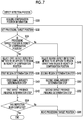
- Fig. 7 is a flowchart illustrating an example of the process in the defect detection step.
- the computer that functions as the image inspection device executes a program to implement each step of the flowchart shown in Fig. 7 .
- the image inspection device acquires compensation position information in Step S30.
- the compensation position information is correction position information indicating the position of an image to which the non-jetting correction process has been applied by the non-jetting correction function of the ink jet printing system.
- the correction position information may be defective nozzle information indicating the position of a defective nozzle subjected to the non-jetting correction process.
- the position of the defective nozzle can be specified by an ink color and a nozzle number.
- the ink jet printing system has a nozzle inspection function that inspects the jetting state of each nozzle in the ink jet head and includes a defective nozzle information storage unit that stores information of a defective nozzle specified by the nozzle inspection function.
- the nozzle inspection function may be, for example, a function that outputs a test chart which is called a ladder pattern, performs image analysis for the output result, and specifies a defective nozzle.
- the ladder pattern is a line pattern in which lines formed by a continuous jetting operation of each nozzle which is performed by so-called "1-on n-off" jetting control for a nozzle column of the ink jet head are arranged.
- a technique for specifying a defective nozzle is not limited to the method using the test chart. For example, there is a method which captures the flying state of liquid droplets jetted from the nozzle, using a camera.
- Step S32 the image inspection device sets a processing target position on the inspection image.
- the processing target position is the position of the image of interest to be subjected to the defect detection process.
- the defect detection process of the image inspection method according to this embodiment determines whether there is a defect at each processing target position while sequentially moving the processing target position on the inspection image.
- Step S34 the image inspection device determines whether the processing target position corresponds to the vicinity of the compensation position. In a case in which the processing target position corresponds to the vicinity of the compensation position, the determination result in Step S34 is "Yes" and the process proceeds to Step S36.
- Step S36 the image inspection device selects a first defect detection method to be applied to the region in the vicinity of the compensation position and performs Step S38, Step S40, and Step S42.
- a first region determination step is an aspect of a processing step of the region determination step described as Step S20 in Fig. 6 .
- a region determination process applied to the processing target position in the region in the vicinity of the compensation position is performed.
- a first signal intensity determination step (Step S40) shown in Fig. 7 is an aspect of a processing step of the signal intensity determination step described as Step S22 in Fig. 6 .
- a signal intensity determination process applied to the processing target position in the region in the vicinity of the compensation position is performed.
- a first defect presence/absence determination step (Step S42) shown in Fig. 7 is an aspect of a processing step of the defect presence/absence determination step described as Step S24 in Fig. 6 .
- a defect presence/absence determination process applied to the processing target position in the region in the vicinity of the compensation position is performed.
- Step S34 In a case in which the processing target position does not correspond to the region in the vicinity of the compensation position, that is, the processing target position corresponds to the region other than the region in the vicinity of the compensation position in Step S34, the process proceeds to Step S46.
- Step S46 the image inspection device selects a second defect detection method to be applied to the region other than the region in the vicinity of the compensation position and performs Step S48, Step S50, and Step S52.
- a second region determination step is an aspect of a processing step of the region determination step described as Step S20 in Fig. 6 .
- a region determination process applied to the processing target position in the region other than the region in the vicinity of the compensation position is performed.
- a second signal intensity determination step (Step S50) shown in Fig. 7 is an aspect of a processing step of the signal intensity determination step described as Step S22 in Fig. 6 .
- a signal intensity determination process applied to the processing target position in the region other than the region in the vicinity of the compensation position is performed.
- a second defect presence/absence determination step (Step S52) shown in Fig. 7 is an aspect of a processing step of the defect presence/absence determination step described as Step S24 in Fig. 6 .
- a defect presence/absence determination process applied to the processing target position in the region other than the region in the vicinity of the compensation position is performed.
- Step S54 the image inspection device determines whether the inspection of the entire region of the inspection image has been completed. In a case in which there is an image position that has not been inspected, the image inspection device proceeds to Step S56, moves the processing target position to the image position that has not been inspected, and returns to Step S32.
- Step S54 the image inspection device ends the process shown in the flowchart of Fig. 7 .
- Step S34 and the process of selecting Step S36 or Step S46 on the basis of the determination result in Step S34 correspond to an example of a selection step.
- Fig. 8 is a block diagram illustrating the functions of an image inspection device 100 according to the embodiment.
- the image inspection device 100 can perform the above-mentioned image inspection method according to the embodiment.
- the image inspection device 100 includes an image acquisition unit 102, a memory 104, a compensation position information acquisition unit 106, a detection method selection control unit 108, and an image analysis unit 110.
- the image analysis unit 110 includes a pre-processing unit 112, a region determination unit 114, a signal intensity determination unit 116, a defect presence/absence determination unit 118, a reference image storage unit 120, a threshold value storage unit 122, and an information output unit 124.
- the image analysis unit 110 may include an arithmetic unit (not illustrated), a processing unit (not illustrated), a storage unit (not illustrated), a control unit (not illustrated) or appropriate combinations thereof, in addition to the components shown in Fig. 8 .
- each unit of the image inspection device 100 may be implemented by a combination of hardware and software of a computer.
- Software is synonymous with a program.
- the detection method selection control unit 108 and the image analysis unit 110 are formed by one central processing unit (CPU) or a plurality of CPUs and are operated by the loading of the program stored in a storage unit (not illustrated) provided in the image inspection device 100 by the CPU.
- some or all of the functions of the image inspection device 100 may be implemented by an integrated circuit typified by a digital signal processor (DSP) or a field-programmable gate array (FPGA).
- DSP digital signal processor
- FPGA field-programmable gate array
- the image acquisition unit 102 is an interface that acquires data of an inspection image 50 from other circuits inside or outside the device.
- the image acquisition unit 102 can be formed by at least one of a data input terminal, a communication interface, or a media interface, or a plurality of combinations thereof.
- the image acquisition unit 102 corresponds to an example of an inspection image acquisition unit.
- the inspection image 50 is, for example, a captured image obtained by capturing a printed matter 130 printed by the line-head-type ink jet printing apparatus (not illustrated in Fig. 8 ) using a camera 132.
- the printed matter 130 corresponds to an example of a recorded matter.
- the captured image may be a gray image with uniform density described in Fig. 2 or may be a general image with an object.
- the camera 132 corresponds to an example of an imaging apparatus.
- the imaging apparatus is an apparatus that converts an optical image into electronic image data, using an imaging element typified by a charge-coupled device (CCD) sensor or a complementary metal-oxide semiconductor device (CMOS) sensor.
- CCD charge-coupled device
- CMOS complementary metal-oxide semiconductor device
- the imaging element may be a two-dimensional image sensor or a line sensor.
- the imaging element may be a color imaging element, a monochromatic imaging element, or a combination thereof.
- the camera 132 may be a scanner.
- the scanner may be a flatbed offline scanner or an in-line sensor that is provided in the medium transport path of the ink jet printing apparatus.
- the term "camera” or “imaging apparatus” is construed as an image reading device that reads a target object and converts the read image into an image signal.
- imaging includes the concept of "reading”.
- the image inspection device 100 acquires the inspection image 50 using the following methods: a method that directly acquires the inspection image 50 from the camera 132; a method that acquires the data of the inspection image 50 obtained by the camera 132 through a wired or wireless communication interface; and a method that acquires the data of the inspection image 50 stored in a memory card or other portable storage media from the portable storage medium through a media interface.
- the image inspection device 100 may include the camera 132 or may not include the camera 132.
- the memory 104 is a storage unit that stores the inspection image 50 acquired through the image acquisition unit 102.
- the memory 104 can function as a work memory when the image analysis unit 110 performs various arithmetic operations.
- the compensation position information acquisition unit 106 is an interface that acquires the compensation position information 32 from other circuits inside or outside the device.
- the compensation position information acquisition unit 106 may be a data input terminal or a communication interface.
- the detection method selection control unit 108 performs control for switching the defect detection method to be applied in the defect detection step, using the compensation position information.
- the pre-processing unit 112 performs pre-processing for the image acquired through the image acquisition unit 102 if necessary.
- the inspection image 50 acquired by the image acquisition unit 102 is data of the image subjected to the pre-processing or data of the image that does not require the pre-processing
- the pre-processed inspection image subjected to predetermined pre-processing by the pre-processing unit 112 is transmitted to the region determination unit 114.
- the inspection image that does not require the pre-processing is transmitted from the memory 104 to the region determination unit 114.
- the region determination unit 114 includes a unit 114A for determining a region in the vicinity of a compensation position which determines an arithmetic target region in the vicinity of the compensation position and a unit 114B for determining a region other than a region in the vicinity of a compensation position which determines an arithmetic target region other than a region in the vicinity of the compensation position.
- a process using the unit 114A for determining the region in the vicinity of the compensation position is selected.
- the region determination unit 114 selects a process using the unit 114B for determining the region other than the region in the vicinity of the compensation position.
- the signal intensity determination unit 116 includes a difference image generation unit 140, a statistical processing unit 142, and a noise reduction unit 144.
- the reference image storage unit 120 stores the data of the reference image 30 that has been generated in advance.
- the reference image 30 is generated by capturing a reference image generating printed matter, which has been recorded in advance by the ink jet printing system according to this embodiment outputting the printed matter 130 or other image recording systems, using the camera 132 or other imaging apparatuses.
- the reference image 30 can be generated on the basis of image data which is used to record the printed matter 130 by the ink jet printing system. In a case in which the reference image is generated on the basis of image data for printing, the reference image may be generated during a process of processing image data in order to output a printed matter.
- the difference image generation unit 140 aligns the positions of the reference image 30 and the inspection image 50 stored in the reference image storage unit 120, calculates the difference between the images, and generates a difference image which is difference image information.
- a storage area of the memory 104 may be used as the reference image storage unit 120.
- a data input terminal (not illustrated) that is used to acquire the data of the reference image 30 from the reference image storage unit 120 by the signal intensity determination unit 116 corresponds to an example of a reference image acquisition unit.
- a data input interface for storing the data of the reference image 30 in the reference image storage unit 120 corresponds to an example of a reference image acquisition unit.
- the statistical processing unit 142 statistically processes a signal of the difference image generated by the difference image generation unit 140 to generate a profile quantitatively indicating the intensity of a signal suspected as a streak or other intensity evaluation signals.
- the statistical processing unit 142 may include a statistical processing unit for the region in the vicinity of the compensation position which is applied to a signal in the region in the vicinity of the compensation position and a statistical processing unit for the region other than the region in the vicinity of the compensation position which is applied to a signal in the region other than the region in the vicinity of the compensation position, which are not illustrated in the drawings.
- the noise reduction unit 144 performs a process of reducing noise in the signal treated by the difference image generation unit 140 and/or the statistical processing unit 142. When the difference image is generated, the noise reduction unit 144 performs the noise reduction process for the reference image 30 and/or the inspection image 50.
- the noise reduction unit 144 may perform the noise reduction process.
- the noise reduction unit 144 includes a noise reduction unit 144A for the region in the vicinity of the compensation position which performs the noise reduction process applied to a signal in the region in the vicinity of the compensation position and a noise reduction unit 144B for the region other than the region in the vicinity of the compensation position which performs the noise reduction process applied to a signal in the region other than the region in the vicinity of the compensation position.
- the defect presence/absence determination unit 118 compares the intensity evaluation signal generated by the signal intensity determination unit 116 with a threshold value to determine whether there is a defect.
- the threshold value storage unit 122 stores the threshold value that is used for the determination process of the defect presence/absence determination unit 118.
- a storage area of the memory 104 may be used as the threshold value storage unit 122.
- the threshold value storage unit 122 can store, for example, a first threshold value that is applied to the region in the vicinity of the compensation position and a second threshold value that is applied to the region other than the region in the vicinity of the compensation position.
- the first threshold value and the second threshold value may be determined by a program or may be input from the operation unit 160.
- the defect presence/absence determination unit 118 can determine whether there is a defect, selectively using one of the first threshold value and the second threshold value, in response to a command from the detection method selection control unit 108.
- the image analysis unit 110 corresponds to an example of a defect detection unit.
- the information output unit 124 is an output interface that outputs information of the determination result of the defect presence/absence determination unit 118.
- Examples of the information of the determination result include information indicating whether there is a streak defect, information indicating the position of a streak defect, information indicating the intensity of a streak, information indicating the length of a streak, and combinations of two or more information items among them.
- the image inspection device 100 may include an operation unit 160 and a display unit 162.
- the operation unit 160 and the display unit 162 form a user interface.
- Various input devices such as a keyboard, a mouse, a touch panel, and a trackball, can be used as the operation unit 160.
- the operation unit 160 may be an appropriate combination thereof.
- Various display devices such as liquid crystal displays, can be used as the display unit 162.
- the display unit 162 and the operation unit 160 may be integrally provided.
- a touch panel may be provided on a screen of the display unit 162. The user can use the operation unit 160 to set various parameters and to input and edit various kinds of information while viewing content displayed on the screen of the display unit 162.
- the display unit 162 functions as inspection result information notification means for notifying the user of the inspection result. For example, In a case in which a streak defect is detected from a printed matter, streak defect detection information indicating the detection information of the streak defect is displayed on the screen of the display unit 162.
- Two patterns that is, a pattern in which a defect occurs in the region in the vicinity of the compensation position and a pattern in which a defect occurs in the region other than the region in the vicinity of the compensation position have been described above.
- a larger number of patterns can be considered.
- the region in the vicinity of the compensation position in the reference image and the region in the vicinity of the compensation position in the inspection image are likely to be separately present.
- the compensation position is likely to be present in the reference image due to pre-processing.
- the compensation position information for each of the above-mentioned patterns may be stored in, for example, a memory and may be used in the defect detection step (Step S14).
- the probability of erroneous determination in this pattern is the highest in defect determination based on the difference image between the inspection image and the reference image.
- robustness against noise is lower than that in pattern 4. Therefore, it is effective to perform different processes for each of the classified patterns.
- the invention is not limited to the configuration in which different processes are applied to four patterns. Processes using different detection methods may be applied to at least pattern 2 and pattern 4.
- first to fourth position sets are defined as follows.
- a set of positions that are not included in the set T and the set R is referred to as the fourth position set.
- Different defect detection methods are selected in at least the second position set and the fourth position set among the first to four position sets defined as described above.
- the defect detection method used in the second position set has a lower correct detection performance and a higher erroneous detection avoidance performance than the defect detection method used in the fourth position set.
- a set of compensation positions is referred to as a compensation position set.
- the following case can be considered as another variation in the compensation position. That is, there is a case in which a compensation position is very close to another compensation position.
- this case is represented by the term "compensation positions are densely arranged”
- the compensation positions which are densely arranged are treated as another pattern and different processes are performed for each pattern.
- the compensation positions which are densely arranged may have the same color or different colors.
- An example of the case in which the compensation positions which are densely arranged have the same color is a case in which defective nozzles are densely arranged in an ink jet head that jets K ink in CMYK printing using ink of four colors, that is, cyan (C), magenta (M), yellow (Y), and black (K).
- An example of the case in which the compensation positions which are densely arranged have different same colors is a case in which a K defective nozzle and a C defective nozzle are densely arranged such as a case in which the position of a defective nozzle of an ink jet head that jets C ink is close to the position of a defective nozzle of an ink jet head that jets K ink.
- the degree of closeness defined as "dense arrangement" can be adjusted according to an application. For example, in a case in which the distance between the compensation nozzles in a nozzle column of a line head with a resolution of 1200 dpi is in the range of about ⁇ 3 to ⁇ 9 nozzles, this case is defined as dense arrangement.
- the strict range of the compensation position treated as "the vicinity of the compensation position" can be adjusted according to an application. Basically, the range of the vicinity of the compensation position is determined according to printing resolution, the number of printing pixels used for compensation, and the imaging resolution of the imaging apparatus. The number of printing pixels used for compensation may be substituted with a compensation width which is the range of the pixels used for compensation.
- the imaging resolution of the imaging apparatus is synonymous with reading resolution.
- the compensation width corresponds to seven nozzles.
- a printed matter output by an ink jet printing apparatus is captured by an imaging apparatus with a reading resolution of 600 pixels per inch (ppi)
- the compensation width is included in the range of 4 to 5 pixels on the captured image. Therefore, it is preferable that at least the range of about ⁇ 3 pixels from the center of the compensation position is defined as the vicinity of the compensation position.
- the captured image is synonymous with a read image.
- the vicinity of the compensation position can be set to the range of about ⁇ 4 pixels from the center of the compensation position. In a case in which the resolution of the imaging apparatus increases, the number of pixels included in the vicinity of the compensation position increases by the increment.
- the compensation positions are densely arranged, it is noted that the number of pixels included in the vicinity of the compensation position further increases. For example, in a case in which two compensation nozzles are close to each other, a range including all of the compensation widths of the two nozzles is determined to be the vicinity of the compensation positions which are densely arranged.
- Fig. 10 is a side view illustrating the configuration of an ink jet printing apparatus 201 according to the embodiment.
- the ink jet printing apparatus 201 corresponds to an example a "printing apparatus".
- the term "printing apparatus” is synonymous with the terms, such as a printing machine, a printer, an image recording apparatus, an image formation apparatus, and an image output apparatus.
- the ink jet printing apparatus 201 is a single-pass line-head-type ink jet printing apparatus that prints a color image on a flat sheet P using a line head.
- the ink jet printing apparatus 201 includes a sheet feed unit 210, a treatment liquid applying unit 220, a treatment liquid drying unit 230, a drawing unit 240, an ink drying unit 250, and a stacking unit 260.
- the sheet feed unit 210 automatically feeds the sheets P one by one.
- the sheet feed unit 210 includes a sheet feed device 212, a feeder board 214, and a sheet feed drum 216.
- the type of sheet P is not particularly limited.
- cellulose-based printing sheets such as a high-quality sheet, a coated sheet, and an art sheet, can be used.
- the sheet P is an example of a recording medium on which an image is recorded. A plurality of sheets P are stacked in a bundle on a sheet feed base 212A.
- the sheet feed device 212 takes out the sheets P which are set in a bundle on the sheet feed base 212A one by one from the top and feeds the sheets to the feeder board 214.
- the feeder board 214 transports the sheet P received from the sheet feed device 212 to the sheet feed drum 216.
- the sheet feed drum 216 receives the sheet P fed from the feeder board 214 and transports the received sheet P to the treatment liquid applying unit 220.
- the treatment liquid applying unit 220 applies a treatment liquid to the sheet P.
- the treatment liquid is a liquid having a function of agglutinating, insolubilizing, or thickening color material components in ink.
- the treatment liquid applying unit 220 includes a treatment liquid applying drum 222 and a treatment liquid applying device 224.
- the treatment liquid applying drum 222 receives the sheet P from the sheet feed drum 216 and transports the received sheet P to the treatment liquid drying unit 230.
- the treatment liquid applying drum 222 includes a gripper 223 provided on a circumferential surface. The treatment liquid applying drum 222 is rotated with the leading end of the sheet P held by the gripper 223 such that the sheet P is wound around the circumferential surface and is transported.
- the treatment liquid applying device 224 applies the treatment liquid onto the sheet P transported by the treatment liquid applying drum 222.
- the treatment liquid is applied by a roller.
- the treatment liquid drying unit 230 dries the sheet P having the treatment liquid applied thereon.
- the treatment liquid drying unit 230 includes a treatment liquid drying drum 232 and a warm air blower 234.
- the treatment liquid drying drum 232 receives the sheet P from the treatment liquid applying drum 222 and transports the received sheet P to the drawing unit 240.
- the treatment liquid drying drum 232 includes grippers 233 provided on a circumferential surface. The treatment liquid drying drum 232 is rotated with the leading end of the sheet P held by the grippers 233 to transport the sheet P.
- the warm air blower 234 is provided inside the treatment liquid drying drum 232.
- the warm air blower 234 blows warm air to the sheet P transported by the treatment liquid drying drum 232 to dry the treatment liquid.
- the drawing unit 240 includes a drawing drum 242, a head unit 244, and an in-line sensor 248.
- the drawing drum 242 receives the sheet P from the treatment liquid drying drum 232 and transports the received sheet P to the ink drying unit 250.
- the drawing drum 242 includes grippers 243 provided on a circumferential surface and is rotated with the leading end of the sheet P held by the grippers 243 such that the sheet P is wound around the circumferential surface and is transported.
- the drawing drum 242 includes a suction mechanism (not illustrated), sucks the sheet P wound around the circumferential surface to the circumferential surface, and transports the sheet P. A negative pressure is used for the suction.
- the drawing drum 242 includes a plurality of suction holes provided in the circumferential surface and draws air to the inside of the drawing drum 242 through the suction holes to suck the sheet P to the circumferential surface of the drawing drum 242.
- the head unit 244 includes ink jet heads 246C, 246M, 246Y, and 246K.
- the ink jet head 246C is a recording head that jets droplets of cyan (C) ink.
- the ink jet head 246M is a recording head that jets droplets of magenta (M) ink.
- the ink jet head 246Y is a recording head that jets droplets of yellow (Y) ink.
- the ink jet head 246K is a recording head that jets droplets of black (K) ink.
- Ink is supplied to each of the ink jet heads 246C, 246M, 246Y, and 246K from ink tanks (not illustrated) which are ink supply sources of corresponding colors through pipe lines (not illustrated).
- the ink jet heads 246C, 246M, 246Y, and 246K are line heads that correspond to a sheet width and are arranged such that each nozzle surface faces the circumferential surface of the drawing drum 242.
- sheet width means the width of a sheet in a direction perpendicular to the transport direction of the sheet P.
- the ink jet heads 246C, 246M, 246Y, and 246K are arranged at regular intervals along the transport path of the sheet P by the drawing drum 242.
- a plurality of nozzles which are ink jetting ports are two-dimensionally arranged on a nozzle surface of each of the ink jet heads 246C, 246M, 246Y, and 246K, which is not illustrated.
- the "nozzle surface” means a jetting surface in which the nozzles are formed and is synonymous with the term “ink jetting surface” or "nozzle formation surface”.
- the two-dimensional arrangement of the plurality of nozzles is referred to as a "two-dimensional nozzle array”.
- Each of the ink jet heads 246C, 246M, 246Y, and 246K can be formed by connecting a plurality of head modules in the width direction of the sheet.
- Each of the ink jet heads 246C, 246M, 246Y, and 246K is a full-line recording head including a nozzle column that can record an image in the entire recording region of the sheet P at a prescribed recording resolution in the width direction of the sheet perpendicular to the transport direction of the sheet P, using one scanning operation.
- the full-line recording head is also called a page-wide head.
- the prescribed recording resolution may be a recording resolution that is set in advance by the ink jet printing apparatus 201 or may be a recording resolution which is selected and set by the user or a recording resolution which is automatically selected and set by a program corresponding to the print mode.
- the recording resolution can be, for example, 1200 dpi.
- the width direction of the sheet perpendicular to the transport direction of the sheet P is referred to as a nozzle column direction of the line head and the transport direction of the sheet P is referred to as a direction perpendicular to a nozzle column.
- a projected nozzle column obtained by projecting (orthographic projection) each nozzle of the two-dimensional nozzle array in the nozzle column direction can be considered to be equivalent to a column of nozzles which are arranged at substantially regular intervals at a nozzle density for achieving the maximum recording resolution in the nozzle column direction.
- the "substantially regular intervals” mean nearly regular intervals at which dots that can be recorded by the ink jet printing apparatus are arranged.
- the concept of "regular intervals" includes a case in which the intervals between the nozzles are slightly different from each other, considering the movement of droplets on a medium due to errors in manufacture or landing interference.
- the projected nozzle column also referred to as a "substantial nozzle column”
- nozzle numbers indicating the positions of each nozzle can be associated with each nozzle in the order in which the projected nozzles are arranged in the nozzle column direction.
- the arrangement of the nozzles in each of the ink jet heads 246C, 246M, 246Y, and 246K is not particularly limited and various nozzle arrays can be used.
- a linear array, a V-shaped nozzle array, and a polygonal-line nozzle array, such as a W-shaped array in which the V-shaped array, which is a unit array, is repeated can be used.
- Ink droplets are jetted from the ink jet heads 246C, 246M, 246Y, and 246K to the sheet P transported by the drawing drum 242 and the jetted droplets are attached to the sheet P. In this way, an image is recorded on the sheet P.
- the drawing drum 242 functions as means for moving the sheet P relative to the ink jet heads 246C, 246M, 246Y, and 246K.
- the drawing drum 242 corresponds to an example of relative movement means for moving the sheet P relative to the ink jet heads 246C, 246M, 246Y, and 246K.
- the jetting timing of each of the ink jet heads 246C, 246M, 246Y, and 246K is synchronized with a rotary encoder signal obtained from a rotary encoder provided in the drawing drum 242.
- the rotary encoder is not illustrated in Fig. 10 and is illustrated as a rotary encoder 382 in Fig. 11 .
- the jetting timing is the time when ink droplets are jetted and is synonymous with droplet drop timing.
- standard colors that is, C, M, Y, and K are used.
- a combination of the ink colors and the number of colors is not limited to this embodiment.
- light ink, dark ink, and special color ink may be added if necessary.
- an ink jet head that jets ink of light colors, such as light cyan and light magenta, may be added or an ink jet head that jets ink of special colors, such as green and orange, may be added.
- the arrangement order of the ink jet heads of each color is not particularly limited.
- An in-line sensor 248 is an image reading device that reads the image recorded on the sheet P by the ink jet heads 246C, 246M, 246Y, and 246K.
- the in-line sensor 248 is, for example, a line scanner using a CCD line sensor.
- the in-line sensor 248 corresponds to an example of an imaging apparatus.
- the in-line sensor 248 can function as the camera 132 described in Fig. 8 .
- a streak defect of a printed matter is detected on the basis of the data of the read image read by the in-line sensor 248.
- information about the density of the image or a jetting failure in the ink jet heads 246C, 246M, 246Y, and 246K is obtained on the basis of the data of the read image read by the in-line sensor 248.
- the camera 132 may be provided separately from the in-line sensor 248, which is not illustrated in the drawings. In a case in which both the in-line sensor 248 and the camera 132 are used, it is preferable that the camera 132 is provided on the downstream side of the in-line sensor 248 in the medium transport direction. For example, the camera 132 is provided at a position where the camera 132 captures an image of a printed matter after the ink drying unit 250 ends the drying process.
- the ink drying unit 250 dries the sheet P on which the image has been recorded by the drawing unit 240.
- the ink drying unit 250 includes a chain delivery 310, a sheet guide 320, and a warm air blowing unit 330.
- the chain delivery 310 receives the sheet P from the drawing drum 242 and transports the received sheet P to the stacking unit 260.
- the chain delivery 310 includes a pair of endless chains 312 that travel along a prescribed travel path and transports the sheet P along the prescribed transport path, with the leading end of the sheet P held by grippers 314 included in the pair of chains 312.
- a plurality of grippers 314 are provided in the chains 312 at regular intervals.
- the sheet guide 320 is a member that guides the transport of the sheet P by the chain delivery 310.
- the sheet guide 320 includes a first sheet guide 322 and a second sheet guide 324.
- the first sheet guide 322 guides the sheet P transported through a first transport section of the chain delivery 310.
- the second sheet guide 324 guides the sheet transported through a second transport section behind the first transport section.
- the warm air blowing unit 330 blows warm air to the sheet P transported by the chain delivery 310.
- the stacking unit 260 includes a stacking device 262 that receives and stacks the sheet P transported from the ink drying unit 250 by the chain delivery 310.
- the chain delivery 310 releases the sheet P at a predetermined stacking position.
- the stacking device 262 includes a stacking tray 262A, receives the sheets P released from the chain delivery 310, and stacks the sheets P on the stacking tray 262A in a bundle.
- the stacking unit 260 corresponds to a sheet discharge unit.
- Fig. 11 is a block diagram illustrating the configuration of a main portion of a control system of the ink jet printing apparatus 201.
- the ink jet printing apparatus 201 is controlled by a control device 202.
- a system including the control device 202 and the ink jet printing apparatus 201 is referred to as an ink jet printing system 300.
- the control device 202 includes a system controller 350, a communication unit 352, a display unit 354, an input device 356, an image processing unit 358, an image inspection device 360, a transport control unit 362, and an image recording control unit 364. Elements of each of the units can be implemented by one computer or a plurality of computers. That is, the control device 202 can be formed by a combination of hardware and software of the computer. In addition, some or all of the processing functions of the control device 202 may be implemented by an integrated circuit typified by a DSP or an FPGA.
- the system controller 350 functions as control means for controlling the overall operation of each unit of the ink jet printing apparatus 201 and also functions as arithmetic means for performing various arithmetic processes.
- the system controller 350 includes a central processing unit (CPU) 370, a read-only memory (ROM) 372, and a random access memory (RAM) 374 and operates according to a predetermined program.
- the ROM 372 stores programs executed by the system controller 350 and various kinds of data required for control.
- the communication unit 352 includes a necessary communication interface.
- the ink jet printing apparatus 201 is connected to a host computer (not illustrated) through the communication unit 352 and can transmit and receive data to and from the host computer.
- the "connection" includes wired connection, wireless connection, and a combination thereof.
- the communication unit 352 may be provided with a buffer memory for increasing a communication rate.
- the communication unit 352 functions as an image input interface unit for acquiring image data indicating the image to be printed.
- the display unit 354 and the input device 356 form a user interface.
- Various input devices such as a keyboard, a mouse, a touch panel, and a trackball, can be used as the input device 356.
- the input device 356 may be an appropriate combination thereof.
- An operator can perform, for example, an operation of inputting various kinds of information, such as printing conditions, other settings, and accessory information, an operation of selecting an image quality mode, an operation of editing accessory information, and an operation of searching for information, using the input device 356, while viewing content displayed on the screen of the display unit 354.
- the operator can check various kinds of information other than input content through the content displayed on the display unit 354.
- the image processing unit 358 performs various kinds of processing, such as a conversion process, a correction process, and halftone processing, for the image data to be printed.
- the conversion process includes, for example, pixel number conversion, gradation conversion, and color conversion.
- the correction process includes density correction and non-jetting correction for preventing an image defect caused by a defective nozzle from being seen.
- the image processing unit 358 performs a correction process on the basis of the read image obtained from the in-line sensor 248.
- the halftone processing is a digital halftoning process typified by a dither method or an error diffusion method.
- the image inspection device 360 can have the same configuration as the image inspection device 100 described in Fig. 8 .
- the display unit 354 shown in Fig. 13 can be used as the display unit 162 described in Fig. 8 .
- the input device 356 shown in Fig. 13 can be used as the operation unit 160 described in Fig. 8 .
- the image inspection device 360 may be formed by a computer different from the control device including the system controller 350 or may be provided as a functional block of the control device including the system controller 350.
- the transport control unit 362 controls a medium transport mechanism 380.
- the medium transport mechanism 380 includes the entire mechanism of the sheet transport unit related to the transport of the sheet P from the sheet feed unit 210 to the stacking unit 260 described in Fig. 10 .
- the medium transport mechanism 380 includes, for example, the sheet feed drum 216, the treatment liquid applying drum 222, the treatment liquid drying drum 232, the drawing drum 242, and the chain delivery 310 illustrated in Fig. 10 .
- the medium transport mechanism 380 includes a driving unit including a motor and a motor driving circuit as a power source (not illustrated).
- the transport control unit 362 controls the medium transport mechanism 380 in response to a command from the system controller 350 such that the sheet P is transported from the sheet feed unit 210 to the stacking unit 260.
- the ink jet printing apparatus 201 includes a rotary encoder 382 as means for detecting the rotation angle of the drawing drum 242 (see Fig. 10 ) in the medium transport mechanism 380.
- the jetting timing of each of the ink jet heads 246C, 246M, 246Y, and 246K is controlled according to a jetting timing signal which is generated from a rotary encoder signal output from the rotary encoder 382.
- the image recording control unit 364 controls the ink jetting operation of each of the ink jet heads 246C, 246M, 246Y, and 246K in response to commands from the system controller 350.
- the image recording control unit 364 controls the jetting operation of each of the ink jet heads 246C, 246M, 246Y, and 246K such that a predetermined image is recorded on the sheet P transported by the drawing drum 242 on the basis of dot data of each ink color generated through the halftone processing of the image processing unit 358.
- the control device 202 includes a storage device (not illustrated) such as a hard disk drive.
- the storage device can store the programs executed by the CPU 370 and various kinds of data required for arithmetic operations.
- the storage device may be provided in the control device 202 or may be connected to the control device 202 through a communication line.
- Fig. 12 is a block diagram illustrating the function of the control device 202 related to image recording control.
- the control device 202 includes a landing error measurement arithmetic unit 410, a defective nozzle information storage unit 412, a density correction coefficient calculation unit 414, a density correction coefficient storage unit 416, a density data generation unit 418, a correction processing unit 420, an ink jetting data generation unit 422, a driving waveform generation unit 424, and a head driver 426.
- the landing error measurement arithmetic unit 410 performs an arithmetic process that generates, for example, data for the position of a non-jetting nozzle or a landing position error and data (density data) indicating a density distribution from the read data of the test chart read from the in-line sensor 248.
- the landing error measurement arithmetic unit 410 determines a nozzle with a landing position error greater than an allowable value to be a defective nozzle that jets liquid droplets in a curved line, on the basis of the data for the landing position error and sets the nozzle as the target to be disabled.
- a process that determines a non-jetting nozzle detected from the read data of the test chart to be a defective nozzle and disables the nozzle is performed.
- the density correction coefficient calculation unit 414 calculates a density correction coefficient from the information of the measured landing position error or density information.
- the process functions of the landing error measurement arithmetic unit 410 and the density correction coefficient calculation unit 414 can be implemented by an integrated circuit, software, or an appropriate combination thereof.
- JP2012-71474A can be used as the detailed content of the processes of the landing error measurement arithmetic unit 410 and the density correction coefficient calculation unit 414.
- the density data generation unit 418 is signal processing means for generating initial density data of each ink color from data of an input image 440 and performs a density conversion process and a pixel number conversion process which is performed if necessary.
- the density conversion process includes an undercoloring process and a color conversion process.
- the correction processing unit 420 is a processing unit that performs density correction using the density correction coefficient stored in the density correction coefficient storage unit 416 and performs a defective nozzle compensation process.
- the correction processing unit 420 performs a process that corrects an image signal for non-jetting correction, using the defective nozzle information stored in the defective nozzle information storage unit 412.
- the defective nozzle information corresponds to compensation position information.
- the ink jetting data generation unit 422 is signal processing means including halftone processing means for converting the corrected image data generated by the correction processing unit 420 into binary or multi-valued dot image data.
- the ink jetting data generation unit 422 generates ink jetting data for controlling the jetting of ink from the dot image data.
- the ink jetting data generated by the ink jetting data generation unit 422 is transmitted to the head driver 426 and the ink jetting operation of the ink jet head 246 is controlled.
- the block of the ink jet head 246 shown in Fig. 12 is a representative example of the ink jet heads corresponding to four colors. In practice, dot image data of each of C, M, Y, and K is generated and the ink jetting operation of the ink jet heads corresponding to each color is controlled.
- the driving waveform generation unit 424 means for generating a driving signal waveform for driving a jetting energy generation element corresponding to each nozzle of the ink jet head 246.
- the jetting energy generation element is, for example, a piezoelectric element.
- a driving waveform signal generated by the driving waveform generation unit 424 is supplied to the head driver 426.
- the signal output from the driving waveform generation unit 424 may be digital waveform data or an analog voltage signal.
- the head driver 426 includes an amplifier circuit and outputs a driving signal for driving the piezoelectric elements corresponding to each nozzle of the ink jet head 246 according to drawing content, on the basis of the ink jetting data and the driving waveform signal.
- the head driver 426 may include a feedback control system for maintaining head driving conditions.
- the driving signal output from the head driver 426 is transmitted to the ink jet head 246 and ink is jetted from the corresponding nozzle.
- the jetting of ink from the ink jet head 246 is controlled in synchronization with the transport speed of the sheet P to form an image on the sheet P.
- the head driver 426 controls the amount of ink droplets jetted from each nozzle or the jetting timing of the ink droplets, on the basis of the ink jetting data and the driving signal waveform generated through necessary signal processing including the process of the correction processing unit 420.
- the correction processing unit 420 performs a process of correcting a signal value required to compensate a defective nozzle for image data before halftone processing.
- correction processing unit 420 may perform the compensation process for image data after halftone processing.
- the compensation process of correcting output image data used for printing has been described.
- a compensation process of correcting a jetting driving signal may be used.
- a program that causes a computer to implement an image processing function including the image inspection function described in the above-mentioned embodiment and the control function of the ink jet printing apparatus can be recorded on a computer readable medium, such as a compact disc read-only memory (CD-ROM), a magnetic disk, or other tangible and non-transitory information storage media, and the program can be provided through the information storage medium.
- a computer readable medium such as a compact disc read-only memory (CD-ROM), a magnetic disk, or other tangible and non-transitory information storage media
- program signals may be provided as a download service through a communication network such as the Internet.
- a service may be performed which provides a portion of or the entire image processing function including the image inspection function as an application server and provides the processing function through a communication network.
- This program is incorporated into the computer to cause the computer to implement the functions of the image inspection device.
- a portion of or the entire program for implementing printing control including the image inspection function described in this embodiment may be incorporated into a high-order control device, such as a host computer, or may be applied as an operating program of the CPU provided in the ink jet printing apparatus.
- An ejector of the ink jet head includes a nozzle that jets a liquid, a pressure chamber that is connected to the nozzle, and a jetting energy generation element that applies jetting energy to the liquid in the pressure chamber.
- means for generating jetting energy is not limited to a piezoelectric element and various jetting energy generation elements, such as a heating element and an electrostatic actuator, can be applied.
- a method can be used which jets liquid droplets using the pressure of film boiling caused by the heating of a liquid by a heating element.
- a jetting energy generating element corresponding to the jetting method of an ink jet head is provided in a flow path structure.
- the "recording medium” means a “medium” used to record an image.
- the “recording medium” or the “medium” is a general term of various media, such as a sheet, a recording sheet, a printing sheet, a printing medium, a typing medium, a printed medium, an image formation medium, an image-formed medium, an image receiving medium, and a medium to which liquid droplets are jetted.
- the material or shape of the recording medium is not particularly limited.
- Various sheets, such as a seal sheet, a resin sheet, a film, fabric, a non-woven fabric, and other materials, may be used, regardless of the material or shape of the recording medium.
- the recording medium is not limited to the sheet-type medium and may be a continuous medium such as continuous paper.
- the sheet-type recording medium is not limited to a cut sheet which has been cut into a prescribed size in advance.
- the continuous medium may be cut into the sheet-type recording media with a prescribed size at any time.
- Transport means for transporting the recording medium is not limited to the drum transport type illustrated in Fig. 1 and various transport types, such as a belt transport type, a nip transport type, a chain transport type, and a pallet transport type, can be used. In addition, these types can be appropriately combined with each other.
- the non-jetting correction parameters are applied to image data before halftone processing to correct a signal value and halftone processing is performed for the corrected image data.
- a structure in which data after halftone processing is corrected may be used.
- a driving signal that is applied to the jetting energy generation element of each nozzle may be corrected.
- the second direction may be a direction perpendicular to the first direction.
- the term "perpendicular” or “vertical” includes an aspect in which the same operation and effect as those in a case in which two directions substantially intersect with each other at an angle of 90° are obtained among the aspects in which two directions intersect each other at an angle less than 90° or at an angle greater than 90°.
- the defective nozzle includes all types of nozzles that abnormally jet ink droplets including a nozzle that intermittently jets ink droplets, such as a nozzle that splashes ink, and a nozzle that jets an ink dot with a size different from a design size, in addition to a non-jetting nozzle and a nozzle that jets ink droplets in a curved line which have been described in Fig. 1 .
- the position where the defective nozzle is compensated is also included in the concept of the "compensation application region" according to this disclosure.
- the invention can be applied to a case in which defects in all types of image recording systems that compensate for the defect of an image formation element are inspected.
- the image recording system include an image recording system that records an image using a thermal print head and an image recording system that records an image using an LED print head.
- printing apparatus is synonymous with the terms, such as a printing machine, a printer, a typewriter, an image recording apparatus, an image formation apparatus, an image output apparatus, and a drawing apparatus.
- image is construed broadly and includes a color image, a black-and-white image, a monochromatic image, a gradation image, and a uniform-density (solid) image.
- image is not limited to a photographed image and is used as the all-encompassing term including a design, a letter, a sign, a drawing line, a mosaic pattern, a coloring pattern, and various other patterns, or appropriate combinations thereof.
- image indicates a digital image.
- the "image recording” includes the concept of the terms, such as image formation, printing, typing, drawing, and print.
- the image recording system includes the concept of the terms, such as an image formation system, a printing system, and a print system.
Landscapes
- Engineering & Computer Science (AREA)
- Quality & Reliability (AREA)
- Theoretical Computer Science (AREA)
- Computer Vision & Pattern Recognition (AREA)
- Physics & Mathematics (AREA)
- General Physics & Mathematics (AREA)
- Multimedia (AREA)
- Signal Processing (AREA)
- General Health & Medical Sciences (AREA)
- Health & Medical Sciences (AREA)
- Artificial Intelligence (AREA)
- Computing Systems (AREA)
- Databases & Information Systems (AREA)
- Evolutionary Computation (AREA)
- Medical Informatics (AREA)
- Software Systems (AREA)
- Biomedical Technology (AREA)
- Ink Jet (AREA)
- Investigating Materials By The Use Of Optical Means Adapted For Particular Applications (AREA)
Claims (14)
- Bildprüfverfahren, umfassend:einen Prüfbild-Erfassungsschritt des Erfassens von Daten eines zu prüfenden Bilds, gewonnen durch Aufnehmen eines Bilds einer Drucksache, die durch ein Bildaufzeichnungssystem aufgezeichnet wurde, welches mehrere Bilderzeugungselemente aufweist und einen Kompensationsprozess des Kompensierens eines Defekts vollzieht, der verursacht ist durch ein Versagen in dem Bilderzeugungselement, unter Verwendung einer Bilderzeugungsvorrichtung;einen Referenzbild-Erfassungsschritt des Erfassens von Daten eines Referenzbilds, bei dem es sich um eine Referenz zum Nachweisen eines Defekts in der Drucksache handelt; undeinen Defektnachweisschritt des Vergleichens der Daten des Prüfbilds mit den Daten des Referenzbilds, um festzustellen, ob ein Defekt an jeder Stelle des Prüfbilds vorliegt,wobei der Defektnachweischritt einen Prozess beinhaltet, der eine Defektnachweisleistung in einer Kompensationsanwendungszone verschieden von einer Defektnachweisleistung in einer Kompensations-Nichtanwendungszone verschieden von der Kompensationsanwendungszone macht, auf der Grundlage von Kompensationsstelleninformation des Versagens in dem Bilderzeugungselement, bei dem der Kompensationsprozess angewendet wurde,wobei die Nachweisleistung eine Defektnachweisgenauigkeit ist, bestimmt durch eine Kombination aus einer Korrektnachweis-Leistung, die exakt einen Defekt in der Drucksache feststellt, und einer Falschnachweis-Vermeidungsleistung, die ein fehlerhaftes Bestimmen einer Nicht-Defektstelle der Drucksache als Defekt vermeidet, undder Defektnachweisschritt einen Prozess beinhaltet, welcher die Falschnachweis-Vermeidungsleistung in der Kompensationsanwendungszone höher einstellt als die Falschnachweis-Vermeidungsleistung in der Kompensations-Nichtanwendungszone.
- Bildprüfverfahren nach Anspruch 1,bei dem in dem Defektnachweisschritt eine Mehrzahl von Defektnachweisverfahren mit verschiedenen Nachweisleistungen definiert werden, undder Defektnachweisschritt einen Auswahlschritt enthält, um aus den mehreren Defektnachweisverfahren auf der Grundlage der Kompensationsstelleninformation ein Defektnachweisverfahren auszuwählen, welches angewendet wird zum Bestimmen, ob es einen Defekt an jeder Stelle gibt.
- Bildprüfverfahren nach Anspruch 2,
bei dem das Defektnachweisverfahren enthält:einen Zonenbestimmungsschritt des Bestimmens einer arithmetischen Zone zum Extrahieren eines Signals, bei dem ein Defekt vermutet wird,einen Signalintensitäts-Bestimmungsschritt des Bestimmens der Intensität des eines Defekts verdächtigen Signals aus der arithmetischen Zone, die durch den Zonenbestimmungsschritt bestimmt wurde, undeinen Defekt-Nichtdefekt-Bestimmungsschritt des Bestimmens, ob es einen Defekt gibt, auf der Grundlage der durch den Signalintensitäts-Bestimmungsschritt bestimmten Intensität des Signals unter Verwendung eines Schwellenwerts, undwobei die mehreren Defektnachweisverfahren Defektnachweisverfahren enthalten, bei denen zumindest arithmetische Verfahren oder Parameter zur Verwendung bei einer arithmetischen Operation in mindestens einem Schritt von dem Zonenbestimmungsschritt, dem Signalintensitäts-Bestimmungsschritt oder dem Defekt-/Nichtdefekt-Bestimmungsschritt verschieden voneinander sind. - Bildprüfverfahren nach Anspruch 3,
bei dem die mehreren Defektnachweisverfahren mindestens eines von folgenden Verfahren enthalten: ein Defektnachweisverfahren, bei dem die arithmetischen Zonen, die in dem Zonenbestimmungsschritt bestimmt wurden, unterschiedliche Größen aufweisen, Defektnachweisverfahren, bei denen arithmetische Verfahren für die arithmetische Operation in dem Signalintensitäts-Bestimmungsschritt oder die Parameter zur Verwendung für die arithmetische Operation in dem Signalintensitäts-Bestimmungsschritt verschieden voneinander sind, und Defektnachweisverfahren, bei denen die Schwellenwerte zur Verwendung in dem Defekt-/Nichtdefekt-Bestimmungsschritt verschieden voneinander sind. - Bildprüfverfahren nach Anspruch 3 oder 4,bei dem der Defekt-/Nichtdefekt-Bestimmungsschritt einen statistischen Bestimmungsprozess enthält, der abschließend statistisch feststellt, ob es einen Defekt gibt, auf der Grundlage einer Bestimmungsdatengruppe für einen Defekt und einen Nicht-Defekt, festgestellt an einer Mehrzahl von Stellen, undBestimmungskriterien des statistischen Bestimmungsprozesses so eingestellt werden, dass sie unterschiedlich sind in der Kompensationsanwendungszone und der Kompensations-Nichtanwendungszone, auf der Grundlage der Kompensationsstelleninformation.
- Bildprüfverfahren nach einem der Ansprüche 2 bis 5,
bei dem für den Fall, dass eine Menge von Kompensationsstellen des Versagens in dem Bilderzeugungselement innerhalb des Prüfbilds eine Menge T sei, eine Menge der Kompensationspositionen des Versagens in dem Bilderzeugungselement innerhalb des Referenzbilds eine Menge R sei, eine Menge an Positionen, die in der Menge T und in der Menge R enthalten sind, eine erste Stellenmenge sei, eine Menge an Stellen, die in der Menge T enthalten und nicht in der Menge R enthalten sind, eine zweite Stellenmenge sei, eine Menge von Stellen, die nicht in der Menge C enthalten sind und in der Menge R enthalten sind, eine dritte Stellenmenge sei, und eine Menge von Stellen, die nicht in der Menge C und in der Menge R enthalten sind, eine vierte Stellenmenge sei, innerhalb des Auswahlschritts unterschiedliche Defektnachweisverfahren ausgebildet werden für mindestens die zweite Stellenmenge und die vierte Stellenmenge. - Bildprüfverfahren nach Anspruch 6,
bei dem unter den mehreren Defektnachweisverfahren das für die zweite Stellenmenge verwendete Defektnachweisverfahren eine größere Falschnachweis-Vermeidungsleistung aufweist als das für die vierte Stellenmenge verwendete Defektnachweisverfahren. - Bildprüfverfahren nach einem der Ansprüche 1 bis 7,
bei dem das Bildaufzeichnungssystem ein Zeilenkopf-Tintenstrahldrucksystem ist und das Bilderzeugungselement eine Düse innerhalb des Zeilenkopfs ist. - Bildprüfverfahren nach Anspruch 8,
bei dem der Kompensationsprozess zum Kompensieren des Versagens in dem Bilderzeugungselement ein Nichtausstoß-Korrekturprozess ist. - Bildprüfverfahren nach einem der Ansprüche 1 bis 9,
bei dem der Defekt ein Streifendefekt ist. - Bildprüfverfahren nach einem der Ansprüche 1 bis 10,bei dem das Referenzbild erzeugt wird durch Aufnehmen eines Bilds einer ein Referenzbild erzeugenden Drucksache, die vorab aufgezeichnet wurde durch das Bildaufzeichnungssystem oder andere Bildaufzeichnungssysteme und der Verwendung der Bildaufzeichnungsvorrichtung oder anderer Bildaufzeichnungsvorrichtungen, oderwobei das Referenzbild erzeugt wird auf der Grundlage von Bilddaten, die dazu dienen, die Drucksache mittels des Bildaufzeichnungssystems aufzuzeichnen.
- Bildprüfvorrichtung (100), umfassend:eine Prüfbild-Erfassungseinheit (102), ausgebildet zum Erfassen von Daten eines Prüfbilds (850), gewonnen durch Aufnehmen eines Bilds einer Drucksache, das aufgezeichnet wurde durch ein Bildaufzeichnungssystem, welches mehrere Bilderzeugungselemente enthält und einen Kompensationsprozess des Kompensierens eines Defekts ausführt, der verursacht wird durch ein Versagen in dem Bilderzeugungselement, unter Verwendung einer Bildgebungsvorrichtung;eine Referenzbild-Erfassungseinheit, ausgebildet zum Erfassen von Daten eines Refernzbilds (30), bei dem es sich um eine Referenz zum Nachweisen eines Defekts in der Drucksache handelt; undeine Defektnachweiseinheit (110), ausgebildet zum Vergleichen der Daten des Prüfbilds (850) mit den Daten des Referenzbilds (30), um festzustellen, ob ein Defekt an jeder Stelle des Prüfbilds vorliegt,wobei die Defektnachweiseinheit (110) ausgebildet ist zum Ausführen eines Prozesses, der eine Defektnachweisleistung in einer Kompensationsanwendungszone verschieden von einer Defektnachweisleistung in einer Kompensations-Nichtanwendungszone verschieden von der Kompensationsanwendungszone macht, auf der Grundlage von Kompensationsstelleninformation des Versagens in dem Bilderzeugungselement, bei dem der Kompensationsprozess angewendet wurde,wobei die Nachweisleistung eine Defektnachweisgenauigkeit ist, festgestellt durch eine Kombination einer korrekten Nachweisleistung, die exakt eine Defekt in der Drucksache feststellt, und einer Falschnachweis-Vermeidungsleistung, die ein fehlerhaftes Bestimmen einer defektfreien Stelle der Drucksache als Defekt vermeidet, unddie Defektnachweiseinheit (110) ausgebildet ist zum Ausführen eines Prozesses, der die Falschnachweis-Vermeidungsleistung in der Kompensationsanwendungszone höher einstellt als die Falschnachweis-Vermeidungsleistung in der Kompensations-Nichtanwendungszone.
- Bildaufzeichnungssystem, umfassend:eine Mehrzahl von Bilderzeugungselementen;eine Kompensationsverarbeitungseinheit, ausgebildet zum Ausführen eines Kompensationsprozesses des Kompensierens eines Defekts, der verursacht wurde durch ein Versagen in dem Bilderzeugungselement, und zum Verringern der Sichtbarkeits des Defekts;eine Bildgebungsvorrichtung, die ein Bild einer Drucksache aufnimmt, die von den Bilderzeugungselementen aufgezeichnet wurde; undeine Bildprüfvorrichtung nach Anspruch 12.
- Computerprogrammprodukt, ausgebildet zum Ausführen des Verfahrens nach einem der Ansprüche 1 bis 11.
Applications Claiming Priority (1)
| Application Number | Priority Date | Filing Date | Title |
|---|---|---|---|
| JP2016193973A JP6694362B2 (ja) | 2016-09-30 | 2016-09-30 | 画像検査方法及び装置、プログラム並びに画像記録システム |
Publications (2)
| Publication Number | Publication Date |
|---|---|
| EP3300907A1 EP3300907A1 (de) | 2018-04-04 |
| EP3300907B1 true EP3300907B1 (de) | 2021-11-17 |
Family
ID=60001688
Family Applications (1)
| Application Number | Title | Priority Date | Filing Date |
|---|---|---|---|
| EP17193402.9A Active EP3300907B1 (de) | 2016-09-30 | 2017-09-27 | Bildüberprüfungsverfahren, bildüberprüfungsvorrichtung, programm und bildaufzeichnungssystem |
Country Status (3)
| Country | Link |
|---|---|
| US (1) | US10311561B2 (de) |
| EP (1) | EP3300907B1 (de) |
| JP (1) | JP6694362B2 (de) |
Families Citing this family (26)
| Publication number | Priority date | Publication date | Assignee | Title |
|---|---|---|---|---|
| WO2017008854A1 (en) * | 2015-07-15 | 2017-01-19 | Hewlett-Packard Indigo B.V. | Image defect detection |
| JP6613214B2 (ja) * | 2016-07-29 | 2019-11-27 | 富士フイルム株式会社 | 印刷物検査装置、印刷物検査方法及びプログラム |
| DE102018201674A1 (de) * | 2017-03-15 | 2018-09-20 | Heidelberger Druckmaschinen Ag | Missing-Nozzle-Korrektur durch Mehrfachraster |
| US10643332B2 (en) * | 2018-03-29 | 2020-05-05 | Uveye Ltd. | Method of vehicle image comparison and system thereof |
| US10650530B2 (en) * | 2018-03-29 | 2020-05-12 | Uveye Ltd. | Method of vehicle image comparison and system thereof |
| JP2019202452A (ja) * | 2018-05-22 | 2019-11-28 | 東芝テック株式会社 | 画像形成装置 |
| CN112889087B (zh) * | 2018-10-15 | 2024-09-17 | 3M创新有限公司 | 对片材部件的自动检查的系统、处理单元和方法 |
| CN109376781B (zh) * | 2018-10-24 | 2022-05-06 | 深圳市腾讯网络信息技术有限公司 | 一种图像识别模型的训练方法、图像识别方法和相关装置 |
| EP3680106B1 (de) | 2019-01-11 | 2023-08-23 | Heidelberger Druckmaschinen AG | Mn-detektion im druckbild |
| JP7181377B2 (ja) * | 2019-03-04 | 2022-11-30 | 富士フイルム株式会社 | 検査方法、プログラム、検査装置、及び印刷装置 |
| JP7126477B2 (ja) * | 2019-06-17 | 2022-08-26 | 富士フイルム株式会社 | 画像検査方法及び装置、プログラム並びに画像記録システム |
| JP7225068B2 (ja) * | 2019-09-18 | 2023-02-20 | 富士フイルム株式会社 | 印刷物の欠陥検査装置、欠陥検査方法及びプログラム、並びに印刷システム |
| KR102260730B1 (ko) * | 2019-11-29 | 2021-06-04 | 한국전자기술연구원 | 바인더 젯팅 적층 제조 방식을 위한 노즐 막힘 결함 보상 방법 |
| JP7372187B2 (ja) * | 2020-03-23 | 2023-10-31 | 株式会社Screenホールディングス | 画像検査装置、印刷装置、および撮像画像の保存処理方法 |
| JP7443925B2 (ja) | 2020-05-15 | 2024-03-06 | コニカミノルタ株式会社 | 画像読取装置、画像読取方法、プログラムおよび画像形成装置 |
| JP7557356B2 (ja) | 2020-12-08 | 2024-09-27 | キヤノン株式会社 | 画像形成システム |
| WO2022154787A1 (en) * | 2021-01-13 | 2022-07-21 | Hewlett-Packard Development Company, L.P. | Image region of interest defect detection |
| CN113211980B (zh) * | 2021-04-21 | 2022-04-22 | 华南理工大学 | 一种用于印刷oled器件的压电控制系统及优化方法 |
| JP7650204B2 (ja) * | 2021-07-19 | 2025-03-24 | キヤノン株式会社 | 画像検査装置および方法、プログラム |
| CN114998241B (zh) * | 2022-05-27 | 2025-04-01 | 上海晶岳电子有限公司 | 一种绝缘栅双极型晶体管功能失效检测方法及系统 |
| CN115760859B (zh) * | 2023-01-10 | 2023-04-25 | 深圳市链科网络科技有限公司 | 一种热敏打印机的打印控制方法及装置 |
| US12240252B2 (en) | 2023-02-21 | 2025-03-04 | Ricoh Company, Ltd. | Automatic tuning compensation mechanism |
| CN116087554B (zh) * | 2023-04-07 | 2023-06-16 | 深圳汝原福永智造科技有限公司 | 风场测试方法和风场测试装置 |
| CN116118363B (zh) * | 2023-04-20 | 2023-07-14 | 杭州百子尖科技股份有限公司 | 一种缺陷智能标记方法、装置、系统及存储介质 |
| CN116452827B (zh) * | 2023-06-16 | 2023-08-15 | 青岛奥维特智能科技有限公司 | 基于计算机视觉的油墨印刷表面质量检测方法及系统 |
| CN117649391B (zh) * | 2023-12-11 | 2024-05-10 | 东莞市中钢模具有限公司 | 基于图像处理的压铸模具缺陷检测方法及系统 |
Citations (1)
| Publication number | Priority date | Publication date | Assignee | Title |
|---|---|---|---|---|
| JP2016140985A (ja) * | 2015-01-30 | 2016-08-08 | コニカミノルタ株式会社 | インクジェット記録装置及びインク吐出不良の検出方法 |
Family Cites Families (23)
| Publication number | Priority date | Publication date | Assignee | Title |
|---|---|---|---|---|
| US5987161A (en) * | 1994-06-30 | 1999-11-16 | Texas Instruments Incorporated | Apparatus and method for identifying defective objects |
| JPH09261497A (ja) * | 1996-03-22 | 1997-10-03 | Minolta Co Ltd | 画像形成装置 |
| US6061476A (en) * | 1997-11-24 | 2000-05-09 | Cognex Corporation | Method and apparatus using image subtraction and dynamic thresholding |
| US6637853B1 (en) * | 1999-07-01 | 2003-10-28 | Lexmark International, Inc. | Faulty nozzle detection in an ink jet printer by printing test patterns and scanning with a fixed optical sensor |
| JP4035974B2 (ja) * | 2001-09-26 | 2008-01-23 | 株式会社日立製作所 | 欠陥観察方法及びその装置 |
| JP3669698B2 (ja) * | 2002-09-20 | 2005-07-13 | 日東電工株式会社 | 印刷物の検査方法及び検査装置 |
| US7138629B2 (en) * | 2003-04-22 | 2006-11-21 | Ebara Corporation | Testing apparatus using charged particles and device manufacturing method using the testing apparatus |
| US20060171593A1 (en) * | 2005-02-01 | 2006-08-03 | Hitachi High-Technologies Corporation | Inspection apparatus for inspecting patterns of a substrate |
| KR101127829B1 (ko) * | 2005-12-07 | 2012-03-20 | 엘지디스플레이 주식회사 | 평판표시장치와 그 제조방법, 제조장치, 화질 제어장치 및화질 제어방법 |
| JP2007256119A (ja) * | 2006-03-23 | 2007-10-04 | Fujitsu Ltd | 検査装置、積層装置、及び検査方法 |
| KR101147083B1 (ko) * | 2006-03-29 | 2012-05-18 | 엘지디스플레이 주식회사 | 화질제어 방법 |
| EP2077920A2 (de) * | 2006-11-02 | 2009-07-15 | University of South Carolina | Verbesserte signalverarbeitung für optische datenverarbeitungssysteme |
| JP2009172966A (ja) * | 2008-01-28 | 2009-08-06 | Fujifilm Corp | 画像出力装置及び異常検出方法 |
| JP4554691B2 (ja) * | 2008-02-25 | 2010-09-29 | アドバンスド・マスク・インスペクション・テクノロジー株式会社 | 補正パターン画像生成装置、パターン検査装置および補正パターン画像生成方法 |
| JP5117423B2 (ja) * | 2009-02-19 | 2013-01-16 | 富士フイルム株式会社 | 画像記録装置、画像処理装置、画像処理方法及びプログラム |
| JP5190998B2 (ja) * | 2009-02-24 | 2013-04-24 | 富士フイルム株式会社 | インクジェット記録装置及び不吐出検知性能の検査方法 |
| JP5398019B2 (ja) | 2010-09-28 | 2014-01-29 | 富士フイルム株式会社 | 不良記録素子補償パラメータ決定方法及び装置、並びに画像形成装置 |
| JP5568456B2 (ja) * | 2010-12-06 | 2014-08-06 | 株式会社日立ハイテクノロジーズ | 荷電粒子線装置 |
| JP5283685B2 (ja) * | 2010-12-17 | 2013-09-04 | 富士フイルム株式会社 | 不良記録素子の検出装置及び方法、並びに画像形成装置及び方法 |
| JP2014066618A (ja) | 2012-09-26 | 2014-04-17 | Dainippon Screen Mfg Co Ltd | 画像検査装置及び画像検査方法並びに画像検査プログラム |
| JP5826787B2 (ja) * | 2013-04-03 | 2015-12-02 | 富士フイルム株式会社 | 画像記録装置及びその制御方法並びにプログラム |
| CN105408990B (zh) * | 2013-06-07 | 2017-10-10 | 联达科技控股有限公司 | 用于自动检验从膜框中正确移除晶粒的系统和方法 |
| JP6039618B2 (ja) * | 2014-08-21 | 2016-12-07 | 富士フイルム株式会社 | 画像処理方法及びプログラム、インクジェット記録装置 |
-
2016
- 2016-09-30 JP JP2016193973A patent/JP6694362B2/ja active Active
-
2017
- 2017-09-27 EP EP17193402.9A patent/EP3300907B1/de active Active
- 2017-09-28 US US15/717,947 patent/US10311561B2/en active Active
Patent Citations (1)
| Publication number | Priority date | Publication date | Assignee | Title |
|---|---|---|---|---|
| JP2016140985A (ja) * | 2015-01-30 | 2016-08-08 | コニカミノルタ株式会社 | インクジェット記録装置及びインク吐出不良の検出方法 |
Also Published As
| Publication number | Publication date |
|---|---|
| JP2018054560A (ja) | 2018-04-05 |
| EP3300907A1 (de) | 2018-04-04 |
| US20180096472A1 (en) | 2018-04-05 |
| US10311561B2 (en) | 2019-06-04 |
| JP6694362B2 (ja) | 2020-05-13 |
Similar Documents
| Publication | Publication Date | Title |
|---|---|---|
| EP3300907B1 (de) | Bildüberprüfungsverfahren, bildüberprüfungsvorrichtung, programm und bildaufzeichnungssystem | |
| EP3305532B1 (de) | Bildinspektionsvorrichtung, bildinspektionsverfahren, programm und tintenstrahldrucksystem | |
| JP6571575B2 (ja) | スジ検出方法及び装置、印刷装置並びにプログラム | |
| JP5619041B2 (ja) | 吐出不良検出方法及び装置、画像処理装置、プログラム、並びに印刷システム | |
| JP5158992B2 (ja) | 不良記録素子の検出装置及び方法、画像形成装置 | |
| US11820133B2 (en) | Image processing method, apparatus, program, and image forming apparatus | |
| US7484821B2 (en) | Method of determining ink ejection method, printing apparatus, and method of manufacturing printing apparatus | |
| JP6472058B2 (ja) | 画像形成装置及び画像補正方法 | |
| US9792514B2 (en) | Image inspection method and apparatus, and ink jet printing apparatus | |
| US9152890B2 (en) | Image recording method and apparatus, and recording medium | |
| KR20170004890A (ko) | 화상 처리장치 및 화상 처리방법 | |
| JP6220029B2 (ja) | インクジェット印刷システム及びその不吐補正方法並びにプログラム | |
| US10576766B2 (en) | Printing apparatus and printing method that correct image data based on a scanning result of an inspection pattern | |
| WO2019107028A1 (ja) | 画像検査方法、画像検査装置、プログラム、及び画像記録システム | |
| US12285943B2 (en) | Printing system and defective nozzle detection method | |
| JP6018994B2 (ja) | インクジェット印刷システム及びその不吐補正方法並びにプログラム | |
| JP5308735B2 (ja) | 印刷画像検査装置および印刷方法 | |
| JP7126477B2 (ja) | 画像検査方法及び装置、プログラム並びに画像記録システム | |
| US20240308236A1 (en) | Printing device and printing method | |
| JP2020037209A (ja) | インクジェット記録装置、インクジェット記録方法、およびプログラム | |
| US20250242601A1 (en) | Landing position deviation amount detection method, printing apparatus, and non-transitory computer-readable recording medium recording landing position deviation amount detection program | |
| JP2018026751A (ja) | 印刷領域検出方法およびそれを用いた印刷装置 |
Legal Events
| Date | Code | Title | Description |
|---|---|---|---|
| PUAI | Public reference made under article 153(3) epc to a published international application that has entered the european phase |
Free format text: ORIGINAL CODE: 0009012 |
|
| STAA | Information on the status of an ep patent application or granted ep patent |
Free format text: STATUS: THE APPLICATION HAS BEEN PUBLISHED |
|
| AK | Designated contracting states |
Kind code of ref document: A1 Designated state(s): AL AT BE BG CH CY CZ DE DK EE ES FI FR GB GR HR HU IE IS IT LI LT LU LV MC MK MT NL NO PL PT RO RS SE SI SK SM TR |
|
| AX | Request for extension of the european patent |
Extension state: BA ME |
|
| STAA | Information on the status of an ep patent application or granted ep patent |
Free format text: STATUS: REQUEST FOR EXAMINATION WAS MADE |
|
| 17P | Request for examination filed |
Effective date: 20180608 |
|
| RBV | Designated contracting states (corrected) |
Designated state(s): AL AT BE BG CH CY CZ DE DK EE ES FI FR GB GR HR HU IE IS IT LI LT LU LV MC MK MT NL NO PL PT RO RS SE SI SK SM TR |
|
| STAA | Information on the status of an ep patent application or granted ep patent |
Free format text: STATUS: EXAMINATION IS IN PROGRESS |
|
| 17Q | First examination report despatched |
Effective date: 20200902 |
|
| RAP3 | Party data changed (applicant data changed or rights of an application transferred) |
Owner name: FUJIFILM CORPORATION |
|
| RIC1 | Information provided on ipc code assigned before grant |
Ipc: B41J 2/21 20060101AFI20210426BHEP Ipc: G06K 9/20 20060101ALI20210426BHEP Ipc: H04N 1/00 20060101ALI20210426BHEP Ipc: G06T 7/00 20170101ALI20210426BHEP Ipc: G06K 15/02 20060101ALI20210426BHEP Ipc: B41J 29/393 20060101ALI20210426BHEP Ipc: H04N 1/60 20060101ALI20210426BHEP Ipc: G06K 9/03 20060101ALI20210426BHEP Ipc: G06K 9/62 20060101ALI20210426BHEP |
|
| GRAP | Despatch of communication of intention to grant a patent |
Free format text: ORIGINAL CODE: EPIDOSNIGR1 |
|
| STAA | Information on the status of an ep patent application or granted ep patent |
Free format text: STATUS: GRANT OF PATENT IS INTENDED |
|
| INTG | Intention to grant announced |
Effective date: 20210621 |
|
| GRAS | Grant fee paid |
Free format text: ORIGINAL CODE: EPIDOSNIGR3 |
|
| GRAA | (expected) grant |
Free format text: ORIGINAL CODE: 0009210 |
|
| STAA | Information on the status of an ep patent application or granted ep patent |
Free format text: STATUS: THE PATENT HAS BEEN GRANTED |
|
| AK | Designated contracting states |
Kind code of ref document: B1 Designated state(s): AL AT BE BG CH CY CZ DE DK EE ES FI FR GB GR HR HU IE IS IT LI LT LU LV MC MK MT NL NO PL PT RO RS SE SI SK SM TR |
|
| REG | Reference to a national code |
Ref country code: GB Ref legal event code: FG4D |
|
| REG | Reference to a national code |
Ref country code: IE Ref legal event code: FG4D |
|
| REG | Reference to a national code |
Ref country code: DE Ref legal event code: R096 Ref document number: 602017049362 Country of ref document: DE |
|
| REG | Reference to a national code |
Ref country code: AT Ref legal event code: REF Ref document number: 1447733 Country of ref document: AT Kind code of ref document: T Effective date: 20211215 |
|
| REG | Reference to a national code |
Ref country code: LT Ref legal event code: MG9D |
|
| REG | Reference to a national code |
Ref country code: NL Ref legal event code: MP Effective date: 20211117 |
|
| REG | Reference to a national code |
Ref country code: AT Ref legal event code: MK05 Ref document number: 1447733 Country of ref document: AT Kind code of ref document: T Effective date: 20211117 |
|
| PG25 | Lapsed in a contracting state [announced via postgrant information from national office to epo] |
Ref country code: RS Free format text: LAPSE BECAUSE OF FAILURE TO SUBMIT A TRANSLATION OF THE DESCRIPTION OR TO PAY THE FEE WITHIN THE PRESCRIBED TIME-LIMIT Effective date: 20211117 Ref country code: LT Free format text: LAPSE BECAUSE OF FAILURE TO SUBMIT A TRANSLATION OF THE DESCRIPTION OR TO PAY THE FEE WITHIN THE PRESCRIBED TIME-LIMIT Effective date: 20211117 Ref country code: FI Free format text: LAPSE BECAUSE OF FAILURE TO SUBMIT A TRANSLATION OF THE DESCRIPTION OR TO PAY THE FEE WITHIN THE PRESCRIBED TIME-LIMIT Effective date: 20211117 Ref country code: BG Free format text: LAPSE BECAUSE OF FAILURE TO SUBMIT A TRANSLATION OF THE DESCRIPTION OR TO PAY THE FEE WITHIN THE PRESCRIBED TIME-LIMIT Effective date: 20220217 Ref country code: AT Free format text: LAPSE BECAUSE OF FAILURE TO SUBMIT A TRANSLATION OF THE DESCRIPTION OR TO PAY THE FEE WITHIN THE PRESCRIBED TIME-LIMIT Effective date: 20211117 |
|
| PG25 | Lapsed in a contracting state [announced via postgrant information from national office to epo] |
Ref country code: IS Free format text: LAPSE BECAUSE OF FAILURE TO SUBMIT A TRANSLATION OF THE DESCRIPTION OR TO PAY THE FEE WITHIN THE PRESCRIBED TIME-LIMIT Effective date: 20220317 Ref country code: SE Free format text: LAPSE BECAUSE OF FAILURE TO SUBMIT A TRANSLATION OF THE DESCRIPTION OR TO PAY THE FEE WITHIN THE PRESCRIBED TIME-LIMIT Effective date: 20211117 Ref country code: PT Free format text: LAPSE BECAUSE OF FAILURE TO SUBMIT A TRANSLATION OF THE DESCRIPTION OR TO PAY THE FEE WITHIN THE PRESCRIBED TIME-LIMIT Effective date: 20220317 Ref country code: PL Free format text: LAPSE BECAUSE OF FAILURE TO SUBMIT A TRANSLATION OF THE DESCRIPTION OR TO PAY THE FEE WITHIN THE PRESCRIBED TIME-LIMIT Effective date: 20211117 Ref country code: NO Free format text: LAPSE BECAUSE OF FAILURE TO SUBMIT A TRANSLATION OF THE DESCRIPTION OR TO PAY THE FEE WITHIN THE PRESCRIBED TIME-LIMIT Effective date: 20220217 Ref country code: NL Free format text: LAPSE BECAUSE OF FAILURE TO SUBMIT A TRANSLATION OF THE DESCRIPTION OR TO PAY THE FEE WITHIN THE PRESCRIBED TIME-LIMIT Effective date: 20211117 Ref country code: LV Free format text: LAPSE BECAUSE OF FAILURE TO SUBMIT A TRANSLATION OF THE DESCRIPTION OR TO PAY THE FEE WITHIN THE PRESCRIBED TIME-LIMIT Effective date: 20211117 Ref country code: HR Free format text: LAPSE BECAUSE OF FAILURE TO SUBMIT A TRANSLATION OF THE DESCRIPTION OR TO PAY THE FEE WITHIN THE PRESCRIBED TIME-LIMIT Effective date: 20211117 Ref country code: GR Free format text: LAPSE BECAUSE OF FAILURE TO SUBMIT A TRANSLATION OF THE DESCRIPTION OR TO PAY THE FEE WITHIN THE PRESCRIBED TIME-LIMIT Effective date: 20220218 Ref country code: ES Free format text: LAPSE BECAUSE OF FAILURE TO SUBMIT A TRANSLATION OF THE DESCRIPTION OR TO PAY THE FEE WITHIN THE PRESCRIBED TIME-LIMIT Effective date: 20211117 |
|
| PG25 | Lapsed in a contracting state [announced via postgrant information from national office to epo] |
Ref country code: SM Free format text: LAPSE BECAUSE OF FAILURE TO SUBMIT A TRANSLATION OF THE DESCRIPTION OR TO PAY THE FEE WITHIN THE PRESCRIBED TIME-LIMIT Effective date: 20211117 Ref country code: SK Free format text: LAPSE BECAUSE OF FAILURE TO SUBMIT A TRANSLATION OF THE DESCRIPTION OR TO PAY THE FEE WITHIN THE PRESCRIBED TIME-LIMIT Effective date: 20211117 Ref country code: RO Free format text: LAPSE BECAUSE OF FAILURE TO SUBMIT A TRANSLATION OF THE DESCRIPTION OR TO PAY THE FEE WITHIN THE PRESCRIBED TIME-LIMIT Effective date: 20211117 Ref country code: EE Free format text: LAPSE BECAUSE OF FAILURE TO SUBMIT A TRANSLATION OF THE DESCRIPTION OR TO PAY THE FEE WITHIN THE PRESCRIBED TIME-LIMIT Effective date: 20211117 Ref country code: DK Free format text: LAPSE BECAUSE OF FAILURE TO SUBMIT A TRANSLATION OF THE DESCRIPTION OR TO PAY THE FEE WITHIN THE PRESCRIBED TIME-LIMIT Effective date: 20211117 Ref country code: CZ Free format text: LAPSE BECAUSE OF FAILURE TO SUBMIT A TRANSLATION OF THE DESCRIPTION OR TO PAY THE FEE WITHIN THE PRESCRIBED TIME-LIMIT Effective date: 20211117 |
|
| REG | Reference to a national code |
Ref country code: DE Ref legal event code: R097 Ref document number: 602017049362 Country of ref document: DE |
|
| PLBE | No opposition filed within time limit |
Free format text: ORIGINAL CODE: 0009261 |
|
| STAA | Information on the status of an ep patent application or granted ep patent |
Free format text: STATUS: NO OPPOSITION FILED WITHIN TIME LIMIT |
|
| 26N | No opposition filed |
Effective date: 20220818 |
|
| PG25 | Lapsed in a contracting state [announced via postgrant information from national office to epo] |
Ref country code: AL Free format text: LAPSE BECAUSE OF FAILURE TO SUBMIT A TRANSLATION OF THE DESCRIPTION OR TO PAY THE FEE WITHIN THE PRESCRIBED TIME-LIMIT Effective date: 20211117 |
|
| PG25 | Lapsed in a contracting state [announced via postgrant information from national office to epo] |
Ref country code: SI Free format text: LAPSE BECAUSE OF FAILURE TO SUBMIT A TRANSLATION OF THE DESCRIPTION OR TO PAY THE FEE WITHIN THE PRESCRIBED TIME-LIMIT Effective date: 20211117 |
|
| PG25 | Lapsed in a contracting state [announced via postgrant information from national office to epo] |
Ref country code: MC Free format text: LAPSE BECAUSE OF FAILURE TO SUBMIT A TRANSLATION OF THE DESCRIPTION OR TO PAY THE FEE WITHIN THE PRESCRIBED TIME-LIMIT Effective date: 20211117 |
|
| REG | Reference to a national code |
Ref country code: CH Ref legal event code: PL |
|
| GBPC | Gb: european patent ceased through non-payment of renewal fee |
Effective date: 20220927 |
|
| REG | Reference to a national code |
Ref country code: BE Ref legal event code: MM Effective date: 20220930 |
|
| PG25 | Lapsed in a contracting state [announced via postgrant information from national office to epo] |
Ref country code: IT Free format text: LAPSE BECAUSE OF FAILURE TO SUBMIT A TRANSLATION OF THE DESCRIPTION OR TO PAY THE FEE WITHIN THE PRESCRIBED TIME-LIMIT Effective date: 20211117 |
|
| P01 | Opt-out of the competence of the unified patent court (upc) registered |
Effective date: 20230515 |
|
| PG25 | Lapsed in a contracting state [announced via postgrant information from national office to epo] |
Ref country code: LU Free format text: LAPSE BECAUSE OF NON-PAYMENT OF DUE FEES Effective date: 20220927 |
|
| PG25 | Lapsed in a contracting state [announced via postgrant information from national office to epo] |
Ref country code: LI Free format text: LAPSE BECAUSE OF NON-PAYMENT OF DUE FEES Effective date: 20220930 Ref country code: IE Free format text: LAPSE BECAUSE OF NON-PAYMENT OF DUE FEES Effective date: 20220927 Ref country code: FR Free format text: LAPSE BECAUSE OF NON-PAYMENT OF DUE FEES Effective date: 20220930 Ref country code: CH Free format text: LAPSE BECAUSE OF NON-PAYMENT OF DUE FEES Effective date: 20220930 |
|
| PG25 | Lapsed in a contracting state [announced via postgrant information from national office to epo] |
Ref country code: BE Free format text: LAPSE BECAUSE OF NON-PAYMENT OF DUE FEES Effective date: 20220930 |
|
| PG25 | Lapsed in a contracting state [announced via postgrant information from national office to epo] |
Ref country code: GB Free format text: LAPSE BECAUSE OF NON-PAYMENT OF DUE FEES Effective date: 20220927 |
|
| PG25 | Lapsed in a contracting state [announced via postgrant information from national office to epo] |
Ref country code: HU Free format text: LAPSE BECAUSE OF FAILURE TO SUBMIT A TRANSLATION OF THE DESCRIPTION OR TO PAY THE FEE WITHIN THE PRESCRIBED TIME-LIMIT; INVALID AB INITIO Effective date: 20170927 |
|
| PG25 | Lapsed in a contracting state [announced via postgrant information from national office to epo] |
Ref country code: CY Free format text: LAPSE BECAUSE OF FAILURE TO SUBMIT A TRANSLATION OF THE DESCRIPTION OR TO PAY THE FEE WITHIN THE PRESCRIBED TIME-LIMIT Effective date: 20211117 |
|
| PG25 | Lapsed in a contracting state [announced via postgrant information from national office to epo] |
Ref country code: MK Free format text: LAPSE BECAUSE OF FAILURE TO SUBMIT A TRANSLATION OF THE DESCRIPTION OR TO PAY THE FEE WITHIN THE PRESCRIBED TIME-LIMIT Effective date: 20211117 |
|
| PG25 | Lapsed in a contracting state [announced via postgrant information from national office to epo] |
Ref country code: TR Free format text: LAPSE BECAUSE OF FAILURE TO SUBMIT A TRANSLATION OF THE DESCRIPTION OR TO PAY THE FEE WITHIN THE PRESCRIBED TIME-LIMIT Effective date: 20211117 |
|
| PG25 | Lapsed in a contracting state [announced via postgrant information from national office to epo] |
Ref country code: MT Free format text: LAPSE BECAUSE OF FAILURE TO SUBMIT A TRANSLATION OF THE DESCRIPTION OR TO PAY THE FEE WITHIN THE PRESCRIBED TIME-LIMIT Effective date: 20211117 |
|
| PGFP | Annual fee paid to national office [announced via postgrant information from national office to epo] |
Ref country code: DE Payment date: 20250805 Year of fee payment: 9 |