EP3299596A1 - Structure de fixation de filtre à huile pour moteur à combustion interne monté sur un véhicule - Google Patents
Structure de fixation de filtre à huile pour moteur à combustion interne monté sur un véhicule Download PDFInfo
- Publication number
- EP3299596A1 EP3299596A1 EP17186658.5A EP17186658A EP3299596A1 EP 3299596 A1 EP3299596 A1 EP 3299596A1 EP 17186658 A EP17186658 A EP 17186658A EP 3299596 A1 EP3299596 A1 EP 3299596A1
- Authority
- EP
- European Patent Office
- Prior art keywords
- internal combustion
- combustion engine
- oil filter
- crankcase
- oil
- Prior art date
- Legal status (The legal status is an assumption and is not a legal conclusion. Google has not performed a legal analysis and makes no representation as to the accuracy of the status listed.)
- Granted
Links
Images


Classifications
-
- F—MECHANICAL ENGINEERING; LIGHTING; HEATING; WEAPONS; BLASTING
- F01—MACHINES OR ENGINES IN GENERAL; ENGINE PLANTS IN GENERAL; STEAM ENGINES
- F01M—LUBRICATING OF MACHINES OR ENGINES IN GENERAL; LUBRICATING INTERNAL COMBUSTION ENGINES; CRANKCASE VENTILATING
- F01M11/00—Component parts, details or accessories, not provided for in, or of interest apart from, groups F01M1/00 - F01M9/00
- F01M11/03—Mounting or connecting of lubricant purifying means relative to the machine or engine; Details of lubricant purifying means
-
- B—PERFORMING OPERATIONS; TRANSPORTING
- B62—LAND VEHICLES FOR TRAVELLING OTHERWISE THAN ON RAILS
- B62K—CYCLES; CYCLE FRAMES; CYCLE STEERING DEVICES; RIDER-OPERATED TERMINAL CONTROLS SPECIALLY ADAPTED FOR CYCLES; CYCLE AXLE SUSPENSIONS; CYCLE SIDE-CARS, FORECARS, OR THE LIKE
- B62K11/00—Motorcycles, engine-assisted cycles or motor scooters with one or two wheels
- B62K11/02—Frames
- B62K11/04—Frames characterised by the engine being between front and rear wheels
-
- B—PERFORMING OPERATIONS; TRANSPORTING
- B65—CONVEYING; PACKING; STORING; HANDLING THIN OR FILAMENTARY MATERIAL
- B65D—CONTAINERS FOR STORAGE OR TRANSPORT OF ARTICLES OR MATERIALS, e.g. BAGS, BARRELS, BOTTLES, BOXES, CANS, CARTONS, CRATES, DRUMS, JARS, TANKS, HOPPERS, FORWARDING CONTAINERS; ACCESSORIES, CLOSURES, OR FITTINGS THEREFOR; PACKAGING ELEMENTS; PACKAGES
- B65D51/00—Closures not otherwise provided for
- B65D51/16—Closures not otherwise provided for with means for venting air or gas
- B65D51/1605—Closures not otherwise provided for with means for venting air or gas whereby the interior of the container is maintained in permanent gaseous communication with the exterior
- B65D51/1616—Closures not otherwise provided for with means for venting air or gas whereby the interior of the container is maintained in permanent gaseous communication with the exterior by means of a filter
-
- F—MECHANICAL ENGINEERING; LIGHTING; HEATING; WEAPONS; BLASTING
- F01—MACHINES OR ENGINES IN GENERAL; ENGINE PLANTS IN GENERAL; STEAM ENGINES
- F01M—LUBRICATING OF MACHINES OR ENGINES IN GENERAL; LUBRICATING INTERNAL COMBUSTION ENGINES; CRANKCASE VENTILATING
- F01M11/00—Component parts, details or accessories, not provided for in, or of interest apart from, groups F01M1/00 - F01M9/00
- F01M11/0004—Oilsumps
-
- F—MECHANICAL ENGINEERING; LIGHTING; HEATING; WEAPONS; BLASTING
- F02—COMBUSTION ENGINES; HOT-GAS OR COMBUSTION-PRODUCT ENGINE PLANTS
- F02B—INTERNAL-COMBUSTION PISTON ENGINES; COMBUSTION ENGINES IN GENERAL
- F02B61/00—Adaptations of engines for driving vehicles or for driving propellers; Combinations of engines with gearing
- F02B61/02—Adaptations of engines for driving vehicles or for driving propellers; Combinations of engines with gearing for driving cycles
-
- F—MECHANICAL ENGINEERING; LIGHTING; HEATING; WEAPONS; BLASTING
- F02—COMBUSTION ENGINES; HOT-GAS OR COMBUSTION-PRODUCT ENGINE PLANTS
- F02B—INTERNAL-COMBUSTION PISTON ENGINES; COMBUSTION ENGINES IN GENERAL
- F02B75/00—Other engines
- F02B75/06—Engines with means for equalising torque
-
- F—MECHANICAL ENGINEERING; LIGHTING; HEATING; WEAPONS; BLASTING
- F02—COMBUSTION ENGINES; HOT-GAS OR COMBUSTION-PRODUCT ENGINE PLANTS
- F02F—CYLINDERS, PISTONS OR CASINGS, FOR COMBUSTION ENGINES; ARRANGEMENTS OF SEALINGS IN COMBUSTION ENGINES
- F02F7/00—Casings, e.g. crankcases or frames
- F02F7/0065—Shape of casings for other machine parts and purposes, e.g. utilisation purposes, safety
- F02F7/0073—Adaptations for fitting the engine, e.g. front-plates or bell-housings
-
- B—PERFORMING OPERATIONS; TRANSPORTING
- B60—VEHICLES IN GENERAL
- B60K—ARRANGEMENT OR MOUNTING OF PROPULSION UNITS OR OF TRANSMISSIONS IN VEHICLES; ARRANGEMENT OR MOUNTING OF PLURAL DIVERSE PRIME-MOVERS IN VEHICLES; AUXILIARY DRIVES FOR VEHICLES; INSTRUMENTATION OR DASHBOARDS FOR VEHICLES; ARRANGEMENTS IN CONNECTION WITH COOLING, AIR INTAKE, GAS EXHAUST OR FUEL SUPPLY OF PROPULSION UNITS IN VEHICLES
- B60K17/00—Arrangement or mounting of transmissions in vehicles
- B60K17/02—Arrangement or mounting of transmissions in vehicles characterised by arrangement, location, or kind of clutch
-
- F—MECHANICAL ENGINEERING; LIGHTING; HEATING; WEAPONS; BLASTING
- F01—MACHINES OR ENGINES IN GENERAL; ENGINE PLANTS IN GENERAL; STEAM ENGINES
- F01M—LUBRICATING OF MACHINES OR ENGINES IN GENERAL; LUBRICATING INTERNAL COMBUSTION ENGINES; CRANKCASE VENTILATING
- F01M11/00—Component parts, details or accessories, not provided for in, or of interest apart from, groups F01M1/00 - F01M9/00
- F01M11/02—Arrangements of lubricant conduits
-
- F—MECHANICAL ENGINEERING; LIGHTING; HEATING; WEAPONS; BLASTING
- F01—MACHINES OR ENGINES IN GENERAL; ENGINE PLANTS IN GENERAL; STEAM ENGINES
- F01M—LUBRICATING OF MACHINES OR ENGINES IN GENERAL; LUBRICATING INTERNAL COMBUSTION ENGINES; CRANKCASE VENTILATING
- F01M11/00—Component parts, details or accessories, not provided for in, or of interest apart from, groups F01M1/00 - F01M9/00
- F01M11/0004—Oilsumps
- F01M2011/0029—Oilsumps with oil filters
-
- F—MECHANICAL ENGINEERING; LIGHTING; HEATING; WEAPONS; BLASTING
- F01—MACHINES OR ENGINES IN GENERAL; ENGINE PLANTS IN GENERAL; STEAM ENGINES
- F01M—LUBRICATING OF MACHINES OR ENGINES IN GENERAL; LUBRICATING INTERNAL COMBUSTION ENGINES; CRANKCASE VENTILATING
- F01M11/00—Component parts, details or accessories, not provided for in, or of interest apart from, groups F01M1/00 - F01M9/00
- F01M11/03—Mounting or connecting of lubricant purifying means relative to the machine or engine; Details of lubricant purifying means
- F01M2011/031—Mounting or connecting of lubricant purifying means relative to the machine or engine; Details of lubricant purifying means characterised by mounting means
-
- F—MECHANICAL ENGINEERING; LIGHTING; HEATING; WEAPONS; BLASTING
- F02—COMBUSTION ENGINES; HOT-GAS OR COMBUSTION-PRODUCT ENGINE PLANTS
- F02F—CYLINDERS, PISTONS OR CASINGS, FOR COMBUSTION ENGINES; ARRANGEMENTS OF SEALINGS IN COMBUSTION ENGINES
- F02F7/00—Casings, e.g. crankcases or frames
- F02F7/0065—Shape of casings for other machine parts and purposes, e.g. utilisation purposes, safety
- F02F7/0073—Adaptations for fitting the engine, e.g. front-plates or bell-housings
- F02F2007/0075—Front covers
Definitions
- the present invention relates to an oil filter attaching structure for a vehicle-mounted internal combustion engine which has a reduced space for installing an oil filter.
- JP 2004-132362 A ( FIGS. 4 , 6 , and 19), indicated below, discloses a vehicle wherein an oil filter for a vehicle-mounted internal combustion engine is installed in a filter case that is integrally formed with a case cover of a crankcase.
- the vehicle disclosed in Patent Document 1 is a rough-terrain four-wheel drive (4WD) vehicle.
- 4WD four-wheel drive
- Some vehicle-mounted internal combustion engines for saddle-type vehicles or the like are smaller in size and challenged by the task of securing an oil filter space.
- the present invention has been made in view of the above prior art. It is an object of the present invention to provide an oil filter attaching structure for a vehicle-mounted internal combustion engine in which an oil filter is installed by a filter case integrally formed with a crankcase cover of a crankcase, the internal combustion engine having a side surface efficiently utilized for making itself smaller in size and for better maintainability.
- an oil filter attaching structure for a vehicle-mounted internal combustion engine in which the internal combustion engine has an oil filter installed in a filter case integrally formed with a crankcase cover of a crankcase, wherein: the crankcase cover is mounted on a side surface of the crankcase so as to cover an end of a crankshaft supported by the crankcase so as to extend in vehicle widthwise directions; an internal combustion engine accessory and a clutch device of an engine transmission are disposed inside of said crankcase cover in respective positions forward and rearward of the crankshaft; and the oil filter and an oil supply port are disposed in said crankcase cover in respective positions upward and downward of the crankshaft.
- the internal combustion engine accessory, the transmission clutch device, the oil filler port, and the oil filter are distributed at respective positions forward, rearward, upward, and downward of the crankshaft on the crankcase cover mounted on the side surface of the crankcase in covering relation to the end of the crankshaft. Therefore, the internal combustion engine has a side surface efficiently utilized for making itself smaller in size and for better maintainability.
- the filter case includes therein a storage cavity having a bottomed tubular shape defined in the crankcase cover and extending toward a center region of the vehicle in a direction along the crankshaft; and the oil filter is housed in the storage cavity with a cap covering the storage cavity.
- the cap is positioned closely to the center of the engine and prevented from protruding from the crankcase cover. Therefore, even the vehicle-mounted internal combustion engine which is small in size provides a space for the oil filter, and has its width reduced.
- a first oil passage and a second oil passage are provided in a wall of the crankcase cover along an inner wall surface thereof, so as to open at an inner circumferential surface of the storage cavity, the cap has an inner cap oil passage defined therein radially outward from an inner cap central space defined in the cap, and the inner cap oil passage is open at an outer circumferential surface of the cap and is in communication with the second oil passage.
- the oil filter is housed in the storage cavity so as to divide the space in the storage cavity into a peripheral space and a central space, the peripheral space is held in fluid communication with the first oil passage, and the central space is held in fluid communication with the second oil passage through the inner cap central space and the inner cap oil passage in the cap.
- both the first oil passage and the second oil passage which serve as an inlet flow path and an outlet flow path for the oil filter, are disposed in a planar layout, and are hence prevented from protruding from the crankcase cover.
- the storage cavity has on an inner bottom surface thereof a cylindrical guide boss for positioning a helical spring for pressing the oil filter toward the cap.
- the helical spring is prevented from being moved by the guide boss and is positioned securely with ease, and the oil filter can be assembled efficiently.
- the storage cavity has an outer bottom surface which is of a shape protruding toward the crankcase beyond a mating surface of the crankcase cover for being mated to the crankcase.
- the internal combustion engine has a balancer drive gear and a balancer driven gear, which are supported by the crankcase with their respective axes parallel to the crankshaft and held in mesh with each other, on the same axial side as the end of the crankshaft; and the storage cavity of the crankcase cover is disposed in a position partly overlapping the balancer drive gear and the balancer driven gear as viewed in a direction along the crankshaft.
- the storage cavity is placed in a space at the axial ends of the large-diameter balancer gear train disposed on the same axial side as the end of the crankshaft and having respective axes extending parallel to the crankshaft.
- the internal combustion engine is thus allowed to be reduced in size.
- the internal combustion engine accessory, the clutch device, the oil supply port, and the oil filter are distributed at respective positions forward, rearward, upward, and downward of the crankshaft on the crankcase cover that is mounted on the side surface of the crankcase in covering relation to the end of the crankshaft. Therefore, the internal combustion engine has a side surface efficiently utilized for making itself smaller in size and for better maintainability.
- the vehicle refers to a saddle-type vehicle that specifically includes a motorcycle 1 illustrated in FIG. 1 .
- the arrow FR represents a forward direction of the vehicle, the arrow LH a leftward direction, the arrow RH a rightward direction, and the arrow UP an upward direction.
- the unnumbered small arrows indicate flows of oil in the internal combustion engine having the oil filter attaching structure according to the present embodiment.
- FIGS. 1 through 10 illustrate the oil filter attaching structure of the vehicle-mounted internal combustion engine according to the present embodiment.
- FIG. 1 illustrates the motorcycle 1 in right-hand side elevation.
- the vehicle-mounted internal combustion engine includes a water-cooled single-cylinder four-valve WOHC four-stroke internal combustion engine having a crankcase 30 that houses a transmission 32 integrally in a rear portion thereof, providing a so-called power unit.
- An internal combustion engine 3 that is mounted on the motorcycle 1 has a crankshaft 31 directed in vehicle widthwise directions of the motorcycle 1, i.e., leftward and rightward directions thereof.
- the motorcycle 1 on which the internal combustion engine 3 is mounted has a vehicle body frame 2 including a pair of left and right main frame rods 21 extending rearward and slightly downward from a head pipe 20 and then gradually bent downward toward rear ends 21a thereof.
- a down frame 22 extends obliquely downward at a sharp angle from the head pipe 20.
- a pair of left and right seat rails 23 extend rearwardly from intermediate portions of the respective left and right main frame rods 21, and are supported by a pair of respective left and right back stays 24 that interconnect central portions of the seat rails 23 and lower portions of the main frame rods 21.
- a front fork 11 is angularly movably supported by the head pipe 20, and a front wheel 12 is rotatably supported on the lower end of the front fork 11.
- a rear fork 13 has a front end angularly movably supported on the rear ends 21a of the main frame rods 21, and extends rearward with a rear wheel 14 rotatably supported on the rear end thereof.
- a rear cushion is interposed between the rear fork 13 and the main frame rods 21.
- a fuel tank 15 is mounted on front portions of the main frame rods 21, and a rider's seat 16 is supported on the seat rails 23 behind the fuel tank 15.
- the internal combustion engine 3 integrally combined with the transmission 32 as described above is suspended from the main frame rods 21 and the down frame 22.
- the internal combustion engine 3 includes a cylinder block 33 and a cylinder head 34 stacked on and fastened to the crankcase 30 with a cylinder axis slightly tilted forward and fastened thereto, and a cylinder head cover 35 mounted on the upper end of the cylinder head 34.
- the internal combustion engine 3 is suspended in an upstanding orientation from the main frame rods 21 and the down frame 22.
- An intake port 36 is open in a rear portion of the cylinder head 34 of the engine 3 and is connected to a throttle body 37 (see FIG. 2 ) that extends to an air cleaner, not illustrated, disposed below the rider's seat 16.
- exhaust pipes 39 are connected to the respective exhaust ports 38 and bent sideways to the left and right.
- the exhaust pipes 39 extend rearward on the left and right sides of the cylinder block 33 of the engine 3 and are connected to left and right mufflers 40 (only the right muffler 40 is illustrated in FIG. 1 ) above the rear wheel 14.
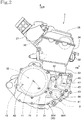
- FIG. 2 is a right-hand side elevational view of the internal combustion engine 3 on the motorcycle 1 illustrated in FIG. 1 .
- the crankcase 30 of the engine 3 includes a pair of left and right crankcase members 30L and 30R that are separably joined to each other (see FIGS. 9 and 10 ).
- FIG. 2 illustrates crosshair marks representing the central axes of the crankshaft 31, a main shaft 41 and a countershaft 42 of the transmission 32, a balancer shaft 43, an oil pump shaft 71, and a coolant pump shaft 45 that are supported in the crankcase 30 parallel to the crankshaft 31.
- the main shaft 41 and the countershaft 42 are positioned behind the crankshaft 31, the balancer shaft 43 and the coolant pump shaft 45 are positioned in front of the crankshaft 31, and the oil pump shaft 71 is positioned below the crankshaft 31.
- the right crankcase member 30R has a right side surface to which there is fastened a right crankcase cover 60R (see FIG.9 ) in covering relation to the right end of the crankshaft 31 and to the positions of the respective shafts 31, 41, 42, 43, 44, and 45.
- a clutch device 50 (see FIG.10 ) is mounted coaxially on the right end of the main shaft 41.
- the right crankcase cover 60R has a clutch opening 61 (see FIG. 3 ) in a rear portion thereof through which the clutch device 50 is inserted.
- the clutch device 50 is disposed inside of the right crankcase cover 60R, and a clutch cover 62 is fastened to the right crankcase cover 60R in covering relation to the right side of the clutch device 50.
- a coolant pump 47 that serves as an internal combustion engine accessory is disposed inside of a front portion of the right crankcase cover 60R, and a water pump cover 46 is attached to the front portion of the right crankcase cover 60R.
- the right crankcase cover 60R has an oil supply port 49 (see FIG.2 ) defined therein above the crankshaft 31 and between the clutch device 50 and the coolant pump 47.
- FIG. 3 illustrates a right outer surface of the right crankcase cover 60R.
- the right crankcase cover 60R has a water pump cover mating surface 68 on its front portion for installing the water pump cover 46 thereon.
- the right crankcase cover 60R also has the clutch opening 61 in its rear portion and a clutch cover mating surface 61a around the clutch opening 61 in its rear portion for fastening the clutch cover 62 thereto.
- An oil filter 8 is provided below the crankshaft 31 substantially intermediate between the water pump cover mating surface 68 and the clutch cover mating surface 61a.
- the oil filter 8 is housed in a storage cavity 80 having a bottomed tubular shape defined as an oil filter case in the right crankcase cover 60R and extending toward the center of the vehicle along the axis of the crankshaft 31, and a cap 81 (see FIG. 2 ) covers the opening of the storage cavity 80.
- FIG. 4 is a cross-sectional view taken along line IV-IV of FIG. 3 and line IV-IV of of FIG. 5 (a) , illustrating in cross section the storage cavity 80, the oil filter 8 housed in the storage cavity 80, and the cap 81.
- the cap 81 Since the storage cavity 80 serves as an oil filter case, the cap 81 is positioned closely to the center of the internal combustion engine 3 and prevented from protruding from the right crankcase cover 60R. Therefore, even the vehicle-mounted internal combustion engine 3 which is small in size provides a space for the oil filter 8, and has its width reduced.
- the right crankcase cover 60R has an inlet oil passage 82, as a first oil passage, defined in a wall thereof along an inner wall surface thereof for guiding oil from an oil pump 7, to be described later, to the oil filter 8, and an outlet oil passage 83 (see FIG.3 ), as a second oil passage, defined in the wall thereof along the inner wall surface thereof for guiding oil from the oil filter 8 to an oil reservoir 64 connected to a right axial end 31a (see FIG. 9 ) of the crankshaft 31, the inlet oil passage 82 and the outlet oil passage 83 having respective ends that are open at an inner circumferential surface 80c (see FIG.3 ) of the storage cavity 80.
- the coolant pump 47 as an internal combustion engine accessory and the clutch device 50 are disposed inside of the right crankcase cover 60R in respective positions forwardly and rearwardly facing the crankshaft 31, and the oil supply port 49 and the oil filter 8 are also disposed inside of the right crankcase cover 60R in respective positions above and below the crankshaft 31, these devices and components are distributed around the crankshaft 31. Therefore, the right side surface of the internal combustion engine 3 is efficiently utilized for making itself smaller in size and for better maintainability.
- the coolant pump 47 may be replaced with another internal combustion engine accessory.
- the inlet oil passage 82 and the outlet oil passage 83 that are connected to the storage cavity 80 do not extend parallel to the crankshaft 31, but are defined in the wall of the right crankcase cover 60R along the inner wall surface thereof, no space for defining oil passages therein is required along the axis of the crankshaft 31. Therefore, the oil filter 8 is positioned closely to the crankshaft 31, allowing the internal combustion engine 3 to be reduced in size.
- the oil filter 8 includes an assembly of a filter element 85 having an annular or cylindrical shape, an oil-permeable tube 86 fitted in the internal space of the filter element 85, and a bottom stiffening plate 87 and an opening stiffening plate 88 that are fitted over the opposite ends of the filter element 85 and the oil-permeable tube 86, the assembly being housed in the storage cavity 80.
- the oil filter 8 is normally biased toward the cap 81 by a helical spring 89 placed in the storage cavity 80.
- One end of the helical spring 89 is fitted over and positioned by a central cylindrical guide boss 80b formed on an inner bottom surface 80a of the storage cavity 80.
- the other end of the helical spring 89 is inserted in a spring housing recess 87a defined centrally in the bottom stiffening plate 87.
- the helical spring 89 When the oil filter 8 is placed into and removed from the storage cavity 80, the helical spring 89 is prevented from being moved or dislodged off by the guide boss 80b. As the helical spring 89 is thus positioned securely with ease, the oil filter 8 can be assembled and disassembled efficiently.
- the cap 81 is mounted on the right crankcase cover 60R and has its outer circumferential surface 81c (see FIG. 5 (a) ) held against the inner circumferential surface 80c of the storage cavity 80 with a seal 90 interposed therebetween.
- the cap 81 is fastened to the right crankcase cover 60R by bolts 84.
- the cap 81 has an outlet boss 81a having a tubular shape formed on a central inner surface thereof and projecting into the storage cavity 80, the outlet boss 81a being open into the storage cavity 80.
- the space in the outlet boss 81a is referred to as an inner cap central space 81b.
- the opening stiffening plate 88 of the oil filter 8 has a central opening 88a defined therein which is fitted over the outlet boss 81a of the cap 81 with a seal 91 interposed therebetween.
- FIG. 5 (a) is a view taken along line V-V of FIG. 4 , illustrating the cap 81 only
- FIG. 5 (b) is a cross-sectional view taken along line b-b of FIG. 5 (a) . It is to be noted that the cross-sectional view of the cap 81 in FIG. 4 corresponds to the cross sectional view taken along line IV-IV in FIG. 5 (a) .
- the cap 81 includes a bulge 81d formed to extend to the inner surface 80c of the storage cavity 80 and extending radially outwardly from the outlet boss 81a to the outer circumferential surface 81c of the cap 81.
- the bulge 81d defines therein an inner cap oil passage 81e extending radially outward from the inner cap central space 81b in the outlet boss 81a to the outer circumferential surface 81c of the cap 81 where the inner cap oil passage 81e is open.
- the space in the storage cavity 80 is divided into a peripheral space 92 and a central space 93 by the oil filter 8 positioned in the storage cavity 80 by the cap 81.
- the peripheral space 92 is held in fluid communication with an end of the inlet oil passage 82 that is defined in the inner wall surface of the right crankcase cover 60R.
- the central space 93 is held in fluid communication with an end of the outlet oil passage 83 through an L-shaped oil passage that includes the inner cap central space 81b and the inner cap oil passage 81e in the cap 81.
- both the inlet oil passage 82 and the outlet oil passage 83 for the oil filter 8 are disposed in a planar layout in the wall of the right crankcase cover 60R along the inner wall surface thereof, and are hence prevented from protruding from the right crankcase cover 60R.
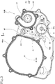
- FIG. 6 is a left-hand side elevational view illustrating the inner wall surface of the right crankcase cover 60R illustrated in FIG. 3 .
- the right crankcase cover 60R has a mating surface 60Ra extending around the inner wall surface thereof for being mated to the right crankcase member 30R.
- the storage cavity 80 has an outer bottom surface 80d protruding forward and downward of the clutch opening 61.
- the inlet oil passage 82 that is defined in the inner wall surface of the right crankcase cover 60R extends slightly downward and rearward (to the right in FIG. 6 ) from the storage cavity 80.
- the inlet oil passage 82 has an end, remote from the storage cavity 80, that serves as a joint opening 82a connected to a pump outlet port 73 (see FIG. 9 ) of the oil pump 7.
- the outlet oil passage 83 that is defined in the inner wall surface of the right crankcase cover 60R extends obliquely upward and rearward (to the right in FIG. 6 ) from the storage cavity 80.
- the outlet oil passage 83 has an end, remote from the storage cavity 80, into which the right end 31a (see FIG. 9 ) of the crankshaft 31 is inserted in a fluid-tight manner, where the oil reservoir 64 for supplying oil to an inner shaft oil passage 31b defined in the crankshaft 31 is defined.
- a branched oil passage 66 is defined in the inner wall surface of the right crankcase cover 60R and extends slightly forward and upward from the oil reservoir 64, providing an oil supply channel directed to the cylinder head 34, etc.
- FIG. 7 is a cross-sectional view of the right crankcase cover 60R, taken along line VII-VII of FIG. 6 , illustrating in cross section the joint opening 82a, the inlet oil passage 82, the storage cavity 80, the outlet oil passage 83, and the oil reservoir 64.
- the inlet oil passage 82 and the outlet oil passage 83 for the oil filter 8 housed in the storage cavity 80 do not extend parallel to the crankshaft 31, but are defined in the planer layout in the wall of the right crankcase cover 60R along the inner wall surface thereof, as described above.
- the outer bottom surface 80d of the storage cavity 80 projects toward the right crankcase member 30R beyond the mating surface 60Ra of the right crankcase cover 60R for being mated to the right crankcase member 30R.
- the mating surface 60Ra of the right crankcase cover 60R is kept off the surface of the tray. As the mating surface 60Ra is kept out of contact with the surface of the component element tray, the mating surface 60Ra is prevented from being damaged and has its serviceability increased.
- FIG. 8 is a right-hand side elevational view illustrating an outer wall surface of the right crankcase member 30R.
- FIG. 8 illustrates crosshair marks representing the central axes of the crankshaft 31, the main shaft 41 and the countershaft 42 of the transmission 32, the balancer shaft 43, and the oil pump shaft 71, these shafts being positioned inside of the area surrounded by a mating surface 30Ra for being mated to the right crankcase cover 60R.
- the oil pump 7 has a pump body 70 (see FIG. 9 ) formed on the right crankcase member 30R around the oil pump shaft 71.
- a pump outer case 72 (see FIG. 9 ) is mounted on the pump body 70 in covering relation thereto.
- a large-diameter balancer drive gear 52 is mounted on the crankshaft 31, and a large-diameter balancer driven gear 53 is mounted on the balancer shaft 43 that lies parallel to the crankshaft 31.
- the balancer drive gear 52 and the balancer driven gear 53 have the same pitch circle radius as each other, dividing the inter-axis distance between the crankshaft 31 and the balancer shaft 43 into equal distances, and are held in mesh with each other.
- the internal combustion engine 3 includes the balancer drive gear 52 and the balancer driven gear 53, which are supported by the crankcase 30 with their respective axes parallel to the crankshaft 31 and held in mesh with each other, on the same side as the end 31a of the crankshaft 31 (see FIGS. 9 and 10 ).
- the storage cavity 80 of the right crankcase cover 60R is positioned at the location indicated by the two-dot-and-dash line in FIG. 8 .
- FIG. 9 is a fragmentary cross-sectional developed view taken generally along line IX-IX of FIG. 8 , illustrating the internal combustion engine 3.
- the pump outer case 72 mounted on the pump body 70 of the oil pump 7 in covering relation thereto has the pump outlet port 73 connected to the joint opening 82a of the inlet oil passage 82 defined in the inner wall surface of the right crankcase cover 60R. Therefore, oil discharged from the oil pump 7 is delivered to the oil filter 8 in the storage cavity 80.
- Oil that has passed through the oil filter 8 in the storage cavity 80 flows through the outlet oil passage 83 defined in the inner wall surface of the right crankcase cover 60R into the oil reservoir 64. Then, the oil flows from the right end 31a of the crankshaft 31 inserted in a fluid-tight manner in the oil reservoir 64 into the inner shaft oil passage 31b defined in the crankshaft 31.
- the oil is also delivered from the oil reservoir 64 through the branched oil passage 66 defined upward in the inner wall surface of the right crankcase cover 60R, and supplied to lubricate and cool various components in the cylinder head 34, etc.
- FIG. 10 is a fragmentary cross-sectional developed view taken generally along line X-X of FIG. 8 , illustrating the internal combustion engine 3.
- the balancer shaft 43 is supported by the crankcase 30 parallel to and forwardly of the crankshaft 31.
- the balancer drive gear 52 is mounted on the right end 31a of the crankshaft 31, and the balancer driven gear 53, which is of the same pitch circle radius as the balancer drive gear 52, is mounted on a right end of the balancer shaft 43 adjacent to the right crankcase member 30R.
- the balancer drive gear 52 and the balancer driven gear 53 are held in mesh with each other.
- the storage cavity 80 of the right crankcase cover 60R is disposed in a position overlapping the balancer drive gear 52 and the balancer driven gear 53 as viewed along the axis of the crankshaft 31.
- the storage cavity 80 is placed in a space 69 at the axial ends of the large-diameter balancer gear train, i.e., the balancer drive gear 52 and the balancer driven gear 53, disposed on the same side as the end 31a of the crankshaft 31 and extending parallel to the crankshaft 31.
- the space on one side of the internal combustion engine 3 is thus effectively utilized, and the engine 3 has no outwardly protrusive structure for installing the oil filter 8 therein, allowing the internal combustion engine 3 to be reduced in size.
- the balancer drive gear 52 may be mounted on another shaft that lies parallel to the crankshaft 31 and is rotatable at the same speed as the crankshaft 31.
- the vehicle-mounted internal combustion engine is not limited to the internal combustion engine illustrated in the above embodiment, but may be other types of internal combustion engine
- the vehicle is not limited to the motorcycle illustrated in the above embodiment, but may be other types of vehicle including three- or four-wheeled buggies.
- the internal combustion engine has been described as having the illustrated layout in the leftward and rightward directions for illustrative purposes.
- the present invention covers internal combustion engines having other different layouts in the leftward and rightward directions.
Landscapes
- Engineering & Computer Science (AREA)
- Mechanical Engineering (AREA)
- General Engineering & Computer Science (AREA)
- Chemical & Material Sciences (AREA)
- Combustion & Propulsion (AREA)
- Lubrication Details And Ventilation Of Internal Combustion Engines (AREA)
- Lubrication Of Internal Combustion Engines (AREA)
- Cylinder Crankcases Of Internal Combustion Engines (AREA)
Applications Claiming Priority (1)
| Application Number | Priority Date | Filing Date | Title |
|---|---|---|---|
| JP2016188732A JP6444351B2 (ja) | 2016-09-27 | 2016-09-27 | 車載内燃機関のオイルフィルター取付け構造 |
Publications (2)
| Publication Number | Publication Date |
|---|---|
| EP3299596A1 true EP3299596A1 (fr) | 2018-03-28 |
| EP3299596B1 EP3299596B1 (fr) | 2019-12-18 |
Family
ID=59713798
Family Applications (1)
| Application Number | Title | Priority Date | Filing Date |
|---|---|---|---|
| EP17186658.5A Active EP3299596B1 (fr) | 2016-09-27 | 2017-08-17 | Structure de fixation de filtre à huile pour moteur à combustion interne monté sur un véhicule |
Country Status (5)
| Country | Link |
|---|---|
| US (1) | US10443459B2 (fr) |
| EP (1) | EP3299596B1 (fr) |
| JP (1) | JP6444351B2 (fr) |
| AU (1) | AU2017213465B2 (fr) |
| BR (1) | BR102017020214A2 (fr) |
Families Citing this family (3)
| Publication number | Priority date | Publication date | Assignee | Title |
|---|---|---|---|---|
| JP6444351B2 (ja) * | 2016-09-27 | 2018-12-26 | 本田技研工業株式会社 | 車載内燃機関のオイルフィルター取付け構造 |
| JP6781225B2 (ja) * | 2018-09-25 | 2020-11-04 | 本田技研工業株式会社 | 鞍乗り型車両のパワーユニット |
| WO2020121700A1 (fr) * | 2018-12-12 | 2020-06-18 | パナソニックIpマネジメント株式会社 | Dispositif monté sur un véhicule |
Citations (6)
| Publication number | Priority date | Publication date | Assignee | Title |
|---|---|---|---|---|
| JPH0476209A (ja) * | 1990-07-19 | 1992-03-11 | Honda Motor Co Ltd | 4サイクルエンジンのオイル供給装置 |
| US20030098203A1 (en) * | 2001-11-28 | 2003-05-29 | Suzuki Motor Corporation | Motorcycle lubrication oil cooling system |
| JP2004132362A (ja) | 2002-09-18 | 2004-04-30 | Honda Motor Co Ltd | 内燃機関の潤滑装置 |
| US20080096718A1 (en) * | 2002-04-08 | 2008-04-24 | Yamaha Hatsudoki Kabushiki Kaisha | Engine |
| US20090084633A1 (en) * | 2007-09-29 | 2009-04-02 | Yasushi Fujimoto | Structure for disposing oil filter in power unit for motorcycle |
| JP2009162194A (ja) * | 2008-01-10 | 2009-07-23 | Honda Motor Co Ltd | 内燃機関の潤滑構造 |
Family Cites Families (10)
| Publication number | Priority date | Publication date | Assignee | Title |
|---|---|---|---|---|
| JP4376107B2 (ja) * | 2004-03-31 | 2009-12-02 | 本田技研工業株式会社 | 自動2輪車のエアクリーナ装置 |
| JP4614926B2 (ja) * | 2006-08-02 | 2011-01-19 | 本田技研工業株式会社 | 内燃機関のオイル注入構造 |
| JP5086202B2 (ja) * | 2008-07-31 | 2012-11-28 | 本田技研工業株式会社 | 内燃機関 |
| JP5890761B2 (ja) * | 2012-07-27 | 2016-03-22 | 本田技研工業株式会社 | 自動二輪車用内燃機関のオイルフィルタ配置構造 |
| JP6444351B2 (ja) * | 2016-09-27 | 2018-12-26 | 本田技研工業株式会社 | 車載内燃機関のオイルフィルター取付け構造 |
| JP6495215B2 (ja) * | 2016-09-27 | 2019-04-03 | 本田技研工業株式会社 | 内燃機関の発電機冷却構造 |
| JP6444352B2 (ja) * | 2016-09-29 | 2018-12-26 | 本田技研工業株式会社 | 単気筒内燃機関 |
| JP6487960B2 (ja) * | 2017-03-30 | 2019-03-20 | 本田技研工業株式会社 | 鞍乗り型車両の内燃機関 |
| JP6484274B2 (ja) * | 2017-03-30 | 2019-03-13 | 本田技研工業株式会社 | 鞍乗り型車両の内燃機関 |
| JP6542829B2 (ja) * | 2017-03-30 | 2019-07-10 | 本田技研工業株式会社 | 鞍乗り型車両用内燃機関 |
-
2016
- 2016-09-27 JP JP2016188732A patent/JP6444351B2/ja active Active
-
2017
- 2017-08-08 AU AU2017213465A patent/AU2017213465B2/en not_active Ceased
- 2017-08-17 EP EP17186658.5A patent/EP3299596B1/fr active Active
- 2017-09-08 US US15/699,932 patent/US10443459B2/en active Active
- 2017-09-21 BR BR102017020214-3A patent/BR102017020214A2/pt active Search and Examination
Patent Citations (6)
| Publication number | Priority date | Publication date | Assignee | Title |
|---|---|---|---|---|
| JPH0476209A (ja) * | 1990-07-19 | 1992-03-11 | Honda Motor Co Ltd | 4サイクルエンジンのオイル供給装置 |
| US20030098203A1 (en) * | 2001-11-28 | 2003-05-29 | Suzuki Motor Corporation | Motorcycle lubrication oil cooling system |
| US20080096718A1 (en) * | 2002-04-08 | 2008-04-24 | Yamaha Hatsudoki Kabushiki Kaisha | Engine |
| JP2004132362A (ja) | 2002-09-18 | 2004-04-30 | Honda Motor Co Ltd | 内燃機関の潤滑装置 |
| US20090084633A1 (en) * | 2007-09-29 | 2009-04-02 | Yasushi Fujimoto | Structure for disposing oil filter in power unit for motorcycle |
| JP2009162194A (ja) * | 2008-01-10 | 2009-07-23 | Honda Motor Co Ltd | 内燃機関の潤滑構造 |
Also Published As
| Publication number | Publication date |
|---|---|
| EP3299596B1 (fr) | 2019-12-18 |
| BR102017020214A2 (pt) | 2018-05-02 |
| JP6444351B2 (ja) | 2018-12-26 |
| AU2017213465A1 (en) | 2018-04-12 |
| US20180087417A1 (en) | 2018-03-29 |
| US10443459B2 (en) | 2019-10-15 |
| AU2017213465B2 (en) | 2018-12-20 |
| JP2018053757A (ja) | 2018-04-05 |
Similar Documents
| Publication | Publication Date | Title |
|---|---|---|
| JP6228131B2 (ja) | エンジンの過給システム | |
| US7198021B2 (en) | Powertrain assembly including modular transmission | |
| US8844493B2 (en) | Lubricating oil feeding structure of engine | |
| EP3299596B1 (fr) | Structure de fixation de filtre à huile pour moteur à combustion interne monté sur un véhicule | |
| EP1918149A1 (fr) | Véhicule à position à califourchon | |
| CN101960175A (zh) | 车辆动力单元 | |
| JP4429610B2 (ja) | 車両用エンジン | |
| JP4316390B2 (ja) | 不整地走行用鞍乗り型四輪車 | |
| JP5883692B2 (ja) | 鞍乗型車両の燃料供給構造 | |
| US9988978B2 (en) | Four-cycle multi-cylinder engine | |
| JP5048618B2 (ja) | 4サイクル空油冷エンジン | |
| JP4901619B2 (ja) | 内燃機関のブリーザ装置 | |
| EP3321480B1 (fr) | Véhicule à enfourcher | |
| EP3301273B1 (fr) | Véhicule de type selle ayant un moteur refroidi par eau | |
| US11378178B2 (en) | Straddle vehicle | |
| US11447001B2 (en) | Hybrid vehicle | |
| US11273698B2 (en) | Hybrid vehicle | |
| US8267052B2 (en) | Engine provided with oil circulation path and cooling fluid path | |
| JP6572805B2 (ja) | エンジンのオイル通路構造 | |
| EP1394382B1 (fr) | Moteur à combustion interne pour un moto-cycle | |
| JP2019178642A (ja) | 鞍乗り型車両 | |
| JP3588514B2 (ja) | 自動二輪車のエアクリーナ装置 | |
| JP3392851B2 (ja) | V型小型液冷式エンジンの冷却液通路構造 | |
| JP4892531B2 (ja) | 車両用エンジンにおける冷却用オイル通路構造 | |
| JP6366193B2 (ja) | 鞍乗り型車両 |
Legal Events
| Date | Code | Title | Description |
|---|---|---|---|
| PUAI | Public reference made under article 153(3) epc to a published international application that has entered the european phase |
Free format text: ORIGINAL CODE: 0009012 |
|
| STAA | Information on the status of an ep patent application or granted ep patent |
Free format text: STATUS: REQUEST FOR EXAMINATION WAS MADE |
|
| 17P | Request for examination filed |
Effective date: 20170817 |
|
| AK | Designated contracting states |
Kind code of ref document: A1 Designated state(s): AL AT BE BG CH CY CZ DE DK EE ES FI FR GB GR HR HU IE IS IT LI LT LU LV MC MK MT NL NO PL PT RO RS SE SI SK SM TR |
|
| AX | Request for extension of the european patent |
Extension state: BA ME |
|
| GRAP | Despatch of communication of intention to grant a patent |
Free format text: ORIGINAL CODE: EPIDOSNIGR1 |
|
| STAA | Information on the status of an ep patent application or granted ep patent |
Free format text: STATUS: GRANT OF PATENT IS INTENDED |
|
| INTG | Intention to grant announced |
Effective date: 20190730 |
|
| GRAS | Grant fee paid |
Free format text: ORIGINAL CODE: EPIDOSNIGR3 |
|
| GRAA | (expected) grant |
Free format text: ORIGINAL CODE: 0009210 |
|
| STAA | Information on the status of an ep patent application or granted ep patent |
Free format text: STATUS: THE PATENT HAS BEEN GRANTED |
|
| AK | Designated contracting states |
Kind code of ref document: B1 Designated state(s): AL AT BE BG CH CY CZ DE DK EE ES FI FR GB GR HR HU IE IS IT LI LT LU LV MC MK MT NL NO PL PT RO RS SE SI SK SM TR |
|
| REG | Reference to a national code |
Ref country code: CH Ref legal event code: EP |
|
| REG | Reference to a national code |
Ref country code: DE Ref legal event code: R096 Ref document number: 602017009792 Country of ref document: DE |
|
| REG | Reference to a national code |
Ref country code: IE Ref legal event code: FG4D |
|
| REG | Reference to a national code |
Ref country code: AT Ref legal event code: REF Ref document number: 1214843 Country of ref document: AT Kind code of ref document: T Effective date: 20200115 |
|
| REG | Reference to a national code |
Ref country code: NL Ref legal event code: MP Effective date: 20191218 |
|
| PG25 | Lapsed in a contracting state [announced via postgrant information from national office to epo] |
Ref country code: FI Free format text: LAPSE BECAUSE OF FAILURE TO SUBMIT A TRANSLATION OF THE DESCRIPTION OR TO PAY THE FEE WITHIN THE PRESCRIBED TIME-LIMIT Effective date: 20191218 Ref country code: LT Free format text: LAPSE BECAUSE OF FAILURE TO SUBMIT A TRANSLATION OF THE DESCRIPTION OR TO PAY THE FEE WITHIN THE PRESCRIBED TIME-LIMIT Effective date: 20191218 Ref country code: BG Free format text: LAPSE BECAUSE OF FAILURE TO SUBMIT A TRANSLATION OF THE DESCRIPTION OR TO PAY THE FEE WITHIN THE PRESCRIBED TIME-LIMIT Effective date: 20200318 Ref country code: SE Free format text: LAPSE BECAUSE OF FAILURE TO SUBMIT A TRANSLATION OF THE DESCRIPTION OR TO PAY THE FEE WITHIN THE PRESCRIBED TIME-LIMIT Effective date: 20191218 Ref country code: LV Free format text: LAPSE BECAUSE OF FAILURE TO SUBMIT A TRANSLATION OF THE DESCRIPTION OR TO PAY THE FEE WITHIN THE PRESCRIBED TIME-LIMIT Effective date: 20191218 Ref country code: GR Free format text: LAPSE BECAUSE OF FAILURE TO SUBMIT A TRANSLATION OF THE DESCRIPTION OR TO PAY THE FEE WITHIN THE PRESCRIBED TIME-LIMIT Effective date: 20200319 Ref country code: NO Free format text: LAPSE BECAUSE OF FAILURE TO SUBMIT A TRANSLATION OF THE DESCRIPTION OR TO PAY THE FEE WITHIN THE PRESCRIBED TIME-LIMIT Effective date: 20200318 |
|
| REG | Reference to a national code |
Ref country code: LT Ref legal event code: MG4D |
|
| PG25 | Lapsed in a contracting state [announced via postgrant information from national office to epo] |
Ref country code: HR Free format text: LAPSE BECAUSE OF FAILURE TO SUBMIT A TRANSLATION OF THE DESCRIPTION OR TO PAY THE FEE WITHIN THE PRESCRIBED TIME-LIMIT Effective date: 20191218 Ref country code: RS Free format text: LAPSE BECAUSE OF FAILURE TO SUBMIT A TRANSLATION OF THE DESCRIPTION OR TO PAY THE FEE WITHIN THE PRESCRIBED TIME-LIMIT Effective date: 20191218 |
|
| PG25 | Lapsed in a contracting state [announced via postgrant information from national office to epo] |
Ref country code: AL Free format text: LAPSE BECAUSE OF FAILURE TO SUBMIT A TRANSLATION OF THE DESCRIPTION OR TO PAY THE FEE WITHIN THE PRESCRIBED TIME-LIMIT Effective date: 20191218 |
|
| PG25 | Lapsed in a contracting state [announced via postgrant information from national office to epo] |
Ref country code: CZ Free format text: LAPSE BECAUSE OF FAILURE TO SUBMIT A TRANSLATION OF THE DESCRIPTION OR TO PAY THE FEE WITHIN THE PRESCRIBED TIME-LIMIT Effective date: 20191218 Ref country code: RO Free format text: LAPSE BECAUSE OF FAILURE TO SUBMIT A TRANSLATION OF THE DESCRIPTION OR TO PAY THE FEE WITHIN THE PRESCRIBED TIME-LIMIT Effective date: 20191218 Ref country code: PT Free format text: LAPSE BECAUSE OF FAILURE TO SUBMIT A TRANSLATION OF THE DESCRIPTION OR TO PAY THE FEE WITHIN THE PRESCRIBED TIME-LIMIT Effective date: 20200513 Ref country code: NL Free format text: LAPSE BECAUSE OF FAILURE TO SUBMIT A TRANSLATION OF THE DESCRIPTION OR TO PAY THE FEE WITHIN THE PRESCRIBED TIME-LIMIT Effective date: 20191218 Ref country code: EE Free format text: LAPSE BECAUSE OF FAILURE TO SUBMIT A TRANSLATION OF THE DESCRIPTION OR TO PAY THE FEE WITHIN THE PRESCRIBED TIME-LIMIT Effective date: 20191218 |
|
| PG25 | Lapsed in a contracting state [announced via postgrant information from national office to epo] |
Ref country code: IS Free format text: LAPSE BECAUSE OF FAILURE TO SUBMIT A TRANSLATION OF THE DESCRIPTION OR TO PAY THE FEE WITHIN THE PRESCRIBED TIME-LIMIT Effective date: 20200418 Ref country code: SK Free format text: LAPSE BECAUSE OF FAILURE TO SUBMIT A TRANSLATION OF THE DESCRIPTION OR TO PAY THE FEE WITHIN THE PRESCRIBED TIME-LIMIT Effective date: 20191218 Ref country code: SM Free format text: LAPSE BECAUSE OF FAILURE TO SUBMIT A TRANSLATION OF THE DESCRIPTION OR TO PAY THE FEE WITHIN THE PRESCRIBED TIME-LIMIT Effective date: 20191218 |
|
| REG | Reference to a national code |
Ref country code: DE Ref legal event code: R097 Ref document number: 602017009792 Country of ref document: DE |
|
| REG | Reference to a national code |
Ref country code: AT Ref legal event code: MK05 Ref document number: 1214843 Country of ref document: AT Kind code of ref document: T Effective date: 20191218 |
|
| PLBE | No opposition filed within time limit |
Free format text: ORIGINAL CODE: 0009261 |
|
| STAA | Information on the status of an ep patent application or granted ep patent |
Free format text: STATUS: NO OPPOSITION FILED WITHIN TIME LIMIT |
|
| PG25 | Lapsed in a contracting state [announced via postgrant information from national office to epo] |
Ref country code: ES Free format text: LAPSE BECAUSE OF FAILURE TO SUBMIT A TRANSLATION OF THE DESCRIPTION OR TO PAY THE FEE WITHIN THE PRESCRIBED TIME-LIMIT Effective date: 20191218 Ref country code: DK Free format text: LAPSE BECAUSE OF FAILURE TO SUBMIT A TRANSLATION OF THE DESCRIPTION OR TO PAY THE FEE WITHIN THE PRESCRIBED TIME-LIMIT Effective date: 20191218 |
|
| PGFP | Annual fee paid to national office [announced via postgrant information from national office to epo] |
Ref country code: DE Payment date: 20200630 Year of fee payment: 4 |
|
| 26N | No opposition filed |
Effective date: 20200921 |
|
| PG25 | Lapsed in a contracting state [announced via postgrant information from national office to epo] |
Ref country code: SI Free format text: LAPSE BECAUSE OF FAILURE TO SUBMIT A TRANSLATION OF THE DESCRIPTION OR TO PAY THE FEE WITHIN THE PRESCRIBED TIME-LIMIT Effective date: 20191218 Ref country code: AT Free format text: LAPSE BECAUSE OF FAILURE TO SUBMIT A TRANSLATION OF THE DESCRIPTION OR TO PAY THE FEE WITHIN THE PRESCRIBED TIME-LIMIT Effective date: 20191218 |
|
| PG25 | Lapsed in a contracting state [announced via postgrant information from national office to epo] |
Ref country code: IT Free format text: LAPSE BECAUSE OF FAILURE TO SUBMIT A TRANSLATION OF THE DESCRIPTION OR TO PAY THE FEE WITHIN THE PRESCRIBED TIME-LIMIT Effective date: 20191218 |
|
| PG25 | Lapsed in a contracting state [announced via postgrant information from national office to epo] |
Ref country code: PL Free format text: LAPSE BECAUSE OF FAILURE TO SUBMIT A TRANSLATION OF THE DESCRIPTION OR TO PAY THE FEE WITHIN THE PRESCRIBED TIME-LIMIT Effective date: 20191218 |
|
| PG25 | Lapsed in a contracting state [announced via postgrant information from national office to epo] |
Ref country code: MC Free format text: LAPSE BECAUSE OF FAILURE TO SUBMIT A TRANSLATION OF THE DESCRIPTION OR TO PAY THE FEE WITHIN THE PRESCRIBED TIME-LIMIT Effective date: 20191218 |
|
| REG | Reference to a national code |
Ref country code: CH Ref legal event code: PL |
|
| PG25 | Lapsed in a contracting state [announced via postgrant information from national office to epo] |
Ref country code: CH Free format text: LAPSE BECAUSE OF NON-PAYMENT OF DUE FEES Effective date: 20200831 Ref country code: LU Free format text: LAPSE BECAUSE OF NON-PAYMENT OF DUE FEES Effective date: 20200817 Ref country code: LI Free format text: LAPSE BECAUSE OF NON-PAYMENT OF DUE FEES Effective date: 20200831 |
|
| REG | Reference to a national code |
Ref country code: BE Ref legal event code: MM Effective date: 20200831 |
|
| PG25 | Lapsed in a contracting state [announced via postgrant information from national office to epo] |
Ref country code: FR Free format text: LAPSE BECAUSE OF NON-PAYMENT OF DUE FEES Effective date: 20200831 |
|
| PG25 | Lapsed in a contracting state [announced via postgrant information from national office to epo] |
Ref country code: IE Free format text: LAPSE BECAUSE OF NON-PAYMENT OF DUE FEES Effective date: 20200817 Ref country code: BE Free format text: LAPSE BECAUSE OF NON-PAYMENT OF DUE FEES Effective date: 20200831 |
|
| REG | Reference to a national code |
Ref country code: DE Ref legal event code: R119 Ref document number: 602017009792 Country of ref document: DE |
|
| GBPC | Gb: european patent ceased through non-payment of renewal fee |
Effective date: 20210817 |
|
| PG25 | Lapsed in a contracting state [announced via postgrant information from national office to epo] |
Ref country code: TR Free format text: LAPSE BECAUSE OF FAILURE TO SUBMIT A TRANSLATION OF THE DESCRIPTION OR TO PAY THE FEE WITHIN THE PRESCRIBED TIME-LIMIT Effective date: 20191218 Ref country code: MT Free format text: LAPSE BECAUSE OF FAILURE TO SUBMIT A TRANSLATION OF THE DESCRIPTION OR TO PAY THE FEE WITHIN THE PRESCRIBED TIME-LIMIT Effective date: 20191218 Ref country code: CY Free format text: LAPSE BECAUSE OF FAILURE TO SUBMIT A TRANSLATION OF THE DESCRIPTION OR TO PAY THE FEE WITHIN THE PRESCRIBED TIME-LIMIT Effective date: 20191218 |
|
| PG25 | Lapsed in a contracting state [announced via postgrant information from national office to epo] |
Ref country code: MK Free format text: LAPSE BECAUSE OF FAILURE TO SUBMIT A TRANSLATION OF THE DESCRIPTION OR TO PAY THE FEE WITHIN THE PRESCRIBED TIME-LIMIT Effective date: 20191218 |
|
| PG25 | Lapsed in a contracting state [announced via postgrant information from national office to epo] |
Ref country code: GB Free format text: LAPSE BECAUSE OF NON-PAYMENT OF DUE FEES Effective date: 20210817 Ref country code: DE Free format text: LAPSE BECAUSE OF NON-PAYMENT OF DUE FEES Effective date: 20220301 |